EP3758568B1 - Buse d'aspiration et appareil d'aspiration portable pour surfaces dures - Google Patents
Buse d'aspiration et appareil d'aspiration portable pour surfaces dures Download PDFInfo
- Publication number
- EP3758568B1 EP3758568B1 EP18707365.5A EP18707365A EP3758568B1 EP 3758568 B1 EP3758568 B1 EP 3758568B1 EP 18707365 A EP18707365 A EP 18707365A EP 3758568 B1 EP3758568 B1 EP 3758568B1
- Authority
- EP
- European Patent Office
- Prior art keywords
- housing
- fixing part
- suction nozzle
- lip
- suction
- Prior art date
- Legal status (The legal status is an assumption and is not a legal conclusion. Google has not performed a legal analysis and makes no representation as to the accuracy of the status listed.)
- Active
Links
Images





Classifications
-
- A—HUMAN NECESSITIES
- A47—FURNITURE; DOMESTIC ARTICLES OR APPLIANCES; COFFEE MILLS; SPICE MILLS; SUCTION CLEANERS IN GENERAL
- A47L—DOMESTIC WASHING OR CLEANING; SUCTION CLEANERS IN GENERAL
- A47L1/00—Cleaning windows
- A47L1/02—Power-driven machines or devices
- A47L1/05—Hand apparatus with built-in electric motors
-
- A—HUMAN NECESSITIES
- A47—FURNITURE; DOMESTIC ARTICLES OR APPLIANCES; COFFEE MILLS; SPICE MILLS; SUCTION CLEANERS IN GENERAL
- A47L—DOMESTIC WASHING OR CLEANING; SUCTION CLEANERS IN GENERAL
- A47L7/00—Suction cleaners adapted for additional purposes; Tables with suction openings for cleaning purposes; Containers for cleaning articles by suction; Suction cleaners adapted to cleaning of brushes; Suction cleaners adapted to taking-up liquids
- A47L7/0004—Suction cleaners adapted to take up liquids, e.g. wet or dry vacuum cleaners
- A47L7/0019—Details of the casing
Definitions
- the invention relates to a suction nozzle for a portable hard surface suction device for removing and sucking off a liquid from a hard surface, in particular from a window pane, with a housing which has a suction opening on a housing front side, which is connected to a suction channel which can be connected to a vacuum source. and with an elastically deformable pull-off lip, which is exchangeably held on the front side of the housing.
- the invention relates to a portable hard surface suction device with such a suction nozzle.
- a suction nozzle and a portable hard surface suction device for scraping and sucking a liquid from a hard surface are from the publication DE 20 2008 018 112 U1 known. They are used in particular to clean window panes, but also to clean other hard surfaces, such as shower cubicle walls, glass doors or tiled walls.
- the suction nozzle has a housing with a housing end face on which a suction opening is arranged.
- a suction channel connects to the suction opening, which can be connected to a negative pressure source of the portable hard surface suction device.
- An elastically deformable pull-off lip is exchangeably held on the front side of the housing and protrudes forwards out of the front side of the housing in the direction away from the suction channel.
- the portable hard surface suction device can be moved along the hard surface with the replaceable squeegee in the manner of a manual window squeegee, so that liquid can be drawn off the hard surface by means of the squeegee.
- the liquid collects at the suction opening of the suction nozzle and a mixture of liquid and air can be sucked out of the suction opening.
- the portable hard surface suction device has a suction unit that is flow-connected to the suction nozzle.
- the separated liquid can be collected in a liquid tank of the portable hard surface suction device, which can be emptied if necessary.
- the extracted air can be discharged from the suction unit to the surroundings of the hard surface suction device.
- the suction nozzle can have an elastically deformable support lip, which is also arranged on the front side of the housing and is covered by the lip.
- the squeegee lip is subject to a certain amount of wear, especially when removing liquid from tiled walls, and should therefore be replaced from time to time.
- U1 known pull-off lip has a thickened area at its rear end that penetrates into the housing, which extends from a first side edge of the pull-off lip to a second side edge and which is received in a form-fitting manner by a receiving channel of the housing aligned parallel to the front side of the housing.
- the pull-off lip can be pulled out of the side of the housing and a new pull-off lip can be pushed into the side of the housing, with the thickening dipping into the receiving channel.
- this requires a high dimensional accuracy of the receiving channel and the thickening.
- replacing the pull-off lip requires a certain level of skill on the part of the user and is often not readily apparent to the user.
- a suction nozzle with the features of the preamble of claim 1 is from EP 3 195 780 A1 known.
- the object of the present invention is therefore to further develop a suction nozzle of the type mentioned at the outset in such a way that the extractor lip can be replaced more easily without the extractor lip and the housing having to have very high dimensional accuracy.
- the suction nozzle according to the invention has a fixing part for fixing the exchangeable pull-off lip on the front side of the housing.
- the locking member is reciprocally movable relative to the housing between a pull-lip locking position (locking position) and a pull-lip releasing position (release position).
- the replaceable pull-off lip can be fixed to the front of the housing with the help of the fixing part.
- the user can move the fixing part into the fixing position.
- the locking part In order to separate the peel-off lip from the housing, the user can move the locking part into a release position in which the locking part releases the peel-off lip. In the release position, the fixing part does not represent an obstacle for the pull-off lip, so that it can be easily separated from the housing.
- Such a configuration makes it easier for the user to replace the pull-off lip, since he only has to move the fixing part from the fixed position into a release position in order to then remove the pull-off lip from the housing. The user can then position another pull-off lip on the housing and then transfer the fixing part back into its fixed position, so that the new pull-off lip is then fixed to the housing by means of the fixing part.
- the fixing part is slidable along an outside of the housing of the suction nozzle.
- the fixing part can be displaced relative to the housing.
- the fixing part can be moved back and forth between the fixed position and the release position without tools. This makes it easier for the user to replace the pull-off lip, since no tools are required for this.
- the user can move the retainer from the retainer position to a release position without tools, then replace the tear lip, and then move the retainer back to the retainer position without tools.
- the housing preferably has a supporting edge on the front side of the housing, on which a rear end section of the pull-off lip can be positioned, and the fixing part has a holding strip which can be positioned on the rear end section of the pull-off lip.
- This makes it possible to fix the pull-off lip to the housing in that its rear end section occupies a position between the supporting edge of the housing and the holding strip of the fixing part.
- the support edge can form a bearing surface for the rear end section of the pull-off lip and thereby support the pull-off lip, and the holding strip can at least partially cover the rear end section of the pull-off lip.
- the holding strip extends from a first side edge of the pull-off lip to a second side edge of the pull-off lip.
- the rear end section of the pull-off lip can be completely covered by the retaining strip between the side edges of the pull-off lip. This enables the pull-off lip to be fixed to the housing with high mechanical loads.
- the rear end section of the pull-off lip and the supporting edge of the housing have projections which are aligned at an angle to a longitudinal axis of the suction nozzle and which engage behind one another.
- the projections that engage behind one another ensure that the pull-off lip cannot easily be pulled forwards, that is to say in the direction away from the suction channel, out of the housing.
- the projections that engage behind one another are aligned at an angle to the longitudinal axis of the suction nozzle.
- an alignment of the projections perpendicular to the longitudinal axis of the suction nozzle has proven to be advantageous.
- the projections can extend perpendicularly to the longitudinal axis along the entire rear end portion of the peel-off lip and along the entire support edge of the housing.
- the fixing part can advantageously be releasably connected to the housing.
- the fixing part forms a force or form fit with the housing in the fixed position and can be moved into the release position if necessary.
- the fixing part can be releasably connected to the housing without tools.
- the user does not need a tool to connect the fixing part to the housing and to release the connection again if necessary.
- the fixing part preferably has at least one first latching element which, in the fixing position, engages behind a second latching element arranged on the housing.
- the at least one first latching element is arranged on a rear side of the fixing part and if the at least one second latching element is arranged on an end section of the suction channel protruding from a rear side of the housing.
- the suction channel extending through the housing has an end section protruding from the rear side of the housing.
- This end section can, for example, be configured so that it can be plugged into a base body of the portable hard surface suction device.
- the end section of the suction channel can be inserted into an inlet channel of the base body to establish a flow connection between the suction nozzle and the suction unit of the hard surface suction device.
- the locking connection between the fixing part and the housing takes place. If the user separates the suction nozzle from the main body of the hard surface suction device, then the end section of the suction nozzle protruding from the rear of the housing is his accessible to the suction channel and he can easily release the latching connection between the at least one first latching element, which is arranged on the rear side of the fixing part, and the at least one second latching element, which is arranged at the end section of the suction channel, in order to move the fixing part into a release position move in which the pull-off lip can be separated from the housing.
- the fixing part can be separated from the housing. This allows the locking part to be completely separated from the body of the suction nozzle in order to replace the lip.
- the fixing part can have a flat configuration.
- the fixing part at least partially covers an outside of the housing in the fixing position.
- the fixing part is arranged on an outside of the housing in the fixing position, and the outside is at least partially covered by the fixing part.
- the fixing part has a cover plate which at least partially covers an outside of the housing when the fixing part is in the fixed position.
- the housing preferably has a receptacle on an outside, into which the fixing part can be inserted.
- the fixing part can initially be displaced along an outside of the housing and can then be separated from the housing.
- the fixing part can be subjected to a holding force directed at the housing by the housing in the fixed position.
- the fixing part is subjected to a force in the direction of the housing in the fixing position.
- Such a configuration is particularly advantageous when a rear end section of the pull-off lip assumes a position between the housing and the fixing part, because by subjecting the fixing part to a holding force in the direction of the housing, it can be ensured in a structurally simple manner that the between rear end portion of the peel-off lip arranged between the fixing part and the housing cannot easily be moved forward in the direction away from the suction channel.
- the fixing part preferably has first holding elements which, in the fixing position of the fixing part, can be acted upon by second holding elements arranged stationarily on the housing with a holding force in the direction of the housing.
- the first and second holding elements can together form a linear guide for moving the fixing part relative to the housing.
- the first and second holding elements in such an embodiment of the invention have a guiding function in that they form a linear guide for the fixing part, so that the fixing part relative to the housing can be moved.
- the first and/or second holding elements are advantageously designed in the form of ribs or L-shape.
- the housing has guide openings into which a first holding element can be inserted, with a second holding element being arranged inside the housing in alignment with the guide openings.
- the first holding elements of the fixing part can each be inserted into a guide opening in the housing and then come to rest against a second holding element of the housing, so that a holding force is then applied to the fixing part, starting from the housing, via the first and second holding elements can be exercised.
- the guide openings are preferably arranged on an end wall of the housing, on the outside of which the pull-off lip is connected.
- the housing can form a support edge on which a rear end section of the pull-off lip can be positioned, which in turn can be covered at least in regions by a retaining strip of the fixing part.
- the housing of the suction nozzle preferably has two housing half-shells which form the suction channel between them.
- the two housing half-shells can be connected to one another by means of connecting screws, the connecting screws being able to be covered by the fixing part when the fixing part is in the fixed position.
- the pull-off lip has a longitudinal section protruding forward from the front side of the housing in the direction away from the suction channel, which is adjoined by a free end section that is inclined toward the longitudinal section in the non-deformed basic position of the pull-off lip.
- the pull-off lip has, for example, an L-shaped profile with a first leg, which forms the longitudinal section, and with a second leg, which is aligned obliquely or perpendicularly to the first leg and forms the forms free end section.
- the free end section can be made significantly shorter than the longitudinal section, so that the profile of the pull-off lip is essentially hook-shaped.
- the suction nozzle can have a supporting lip arranged on the front side of the housing in addition to the replaceable pull-off lip.
- its free end section can extend beyond the free end of the support lip and form a scraper lip edge that can be placed against the hard surface to be cleaned.
- the pull-off lip is reinforced, particularly in its edge regions.
- the pull-off lip has at least one reinforcing rib on its upper side facing away from the supporting lip.
- the pull-off lip has a side edge on each of its longitudinal sides. It is favorable if at least one reinforcing rib is arranged at a distance from each side edge. In particular, it can be provided that two reinforcing ribs running parallel to the side edge are positioned at a distance from each side edge.
- the invention relates not only to a suction nozzle but also to a portable hard surface suction device with a suction nozzle, as explained in more detail above.
- the portable hard-surface suction device is preferably designed as a hand-held device that the user can carry with one hand and move along a hard surface, in particular a window pane, in the manner of a manual window squeegee.
- the portable hard surface suction device has a suction unit which is flow-connected to the suction nozzle stands for suction of a liquid-air mixture from the hard surface.
- the portable hard surface suction device has a separating device, which is arranged in the flow path between the suction nozzle and the suction unit for separating liquid from the suctioned liquid-air mixture.
- the portable hard surface suction device has a liquid tank for receiving the separated liquid.
- a suction flow can be generated at the suction opening of the suction nozzle, under the effect of which a mixture of liquid and air can be sucked into the suction channel.
- the liquid sucked in can be separated from the mixture of liquid and air with the aid of the separating device and transferred to the liquid tank.
- the air sucked in can be discharged to the environment via air outlet openings of the portable hard surface suction device.
- FIG. 1 and 2 an advantageous embodiment of a portable hard surface suction device according to the invention is shown schematically, which is assigned the reference numeral 10 overall.
- the hard surface suction device has an advantageous embodiment of a suction nozzle 12 according to the invention, which is Figures 3 to 16 is shown schematically.
- liquid can be drawn off and sucked off a hard surface, for example from a window pane.
- the hard surface suction device 10 can be moved along the hard surface by the user in the manner of a manual window squeegee.
- the portable hard surface suction device 10 forms in particular a window cleaning device.
- the hard surface suction device 10 comprises a basic body 14 with a basic housing 16 which forms a handle 18 and surrounds a suction unit 20 .
- the suction unit 20 has a suction turbine 22 which is driven by an electric motor 24 .
- the electric motor 24 is supplied with electrical energy by a rechargeable battery 26 arranged inside the handle 18 and can be switched on and off by the user by means of a switch 28 arranged on the handle.
- the basic housing 16 forms a separating chamber 30 in which a separating device 32 , for example a baffle wall, is arranged and which can be subjected to negative pressure by the suction unit 20 .
- the separation chamber 30 is flow-connected to a liquid tank 34 via a liquid outlet, not shown in the drawing, which is detachably held on the basic housing 16 .
- the suction nozzle 12 adjoins the base body 14 on the upper side and can be plugged into the base body 14 .
- the suction nozzle 12 has a housing 36 which is formed by a first housing half-shell 38 and a second housing half-shell 40 .
- the two housing half-shells 38, 40 are screwed together by means of connecting screws 42. This is in particular from the figures 5 and 12 clearly.
- a suction opening 46 is arranged on a housing end face 44 of the housing 36 facing away from the base body 14 and is connected to a suction channel 48 .
- the suction channel 48 extends through the housing 36 and protrudes with a rear end section 50 from a rear side 52 of the housing 36 .
- the rear end section 50 is surrounded by a sealing ring 54 and can be inserted into an inlet channel 56 of the main housing 16 to create a liquid-tight and flow-tight connection between the suction nozzle 12 and the suction unit 20.
- An exchangeable pull-off lip 58 and a supporting lip 60 are arranged on the housing end face 44 of the suction nozzle 12 .
- the pull-off lip 58 and the support lip 60 are elastically deformable.
- the support lip 60 is integrally connected to the second housing half-shell 40 .
- the supporting lip 60 is molded onto the second half-shell 40 of the housing.
- the supporting lip 60 forms an injection-molded part made of two components, the supporting lip 60 forming a soft component of the injection-molded part and the second housing half-shell 40 forming a hard component of the injection-molded part.
- the pull-off lip 58 and the supporting lip 60 protrude forward out of the housing 36 in the direction away from the suction channel 48 .
- the pull-off lip 58 engages behind the free end 62 of the supporting lip 60. It has a longitudinal section 64 adjoining the housing end face 44, which is adjoined by a front end section 66 which is inclined relative to the longitudinal section 64.
- the front end section 66 has a pull-off lip edge 68 which is arranged in front of the free end 62 of the supporting lip 60 in the undeformed basic position shown in the drawing. This is made out in particular figure 5 clearly.
- a rear end section 70 of the pull-off lip 58 which rests on a supporting edge 72 , adjoins the longitudinal section 64 .
- the supporting edge 72 is formed by the first housing half-shell 38 and connects to an end wall 74 of the first housing half-shell 38 at the front.
- the supporting edge 72 On its upper side 76 facing away from the second housing half-shell 40, the supporting edge 72 has a projection 78 with a V-shaped cross section, which extends perpendicularly to a longitudinal axis 80 of the suction nozzle 12 from a first side edge 86 of the stripping lip 58 to a second side edge 88 of the stripping lip of the entire support edge 72 extends.
- the rear end section 70 of the pull-off lip 58 has on its underside 82 facing the supporting edge 72 a projection 84 which engages behind the projection 78 of the supporting edge 72 and extends perpendicularly to the longitudinal axis 80 over the entire rear end section 70 .
- the side edges 86 and 88 of the stripping lip 58 are aligned parallel to the longitudinal axis 80 of the suction nozzle 12 .
- the suction nozzle 12 has a fixing part 100, which serves to fix the replaceable stripping lip 58 on the housing 36.
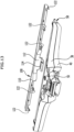
- the fixing part 100 is relative to the housing 36 between a in the Figures 3 to 9 shown fixing position and one in the Figures 10 to 13 shown release position movable back and forth.
- the fixing part 100 can be completely separated from the housing 36, as shown in FIGS Figures 10 to 13 is shown and is releasably connectable to the housing 36 .
- the fixing part 100 has a holding bar 102 which is in the fixed position of the fixing part 100 extends from the first side edge 86 to the second side edge 88 and rests on the rear end section 70 of the replaceable pull-off lip 58, so that the pull-off lip 58 cannot be pulled forwards out of the area between the holding strip 102 and the supporting edge 72 of the housing 36 .
- the first housing half-shell 38 On its upper side facing away from the second housing half-shell 40 , the first housing half-shell 38 has a receptacle 104 which is delimited by a first receiving edge 106 of the first housing half-shell 38 and a second receiving edge 108 of the first housing half-shell 38 .
- the two receiving edges 106, 108 surround the upper-side receptacle 104 of the first housing half-shell 38.
- the receiving edges 106 and 108 each have a front edge region 107 and 109, respectively, which extends forward beyond the receptacle 104 to the free end of the supporting edge 72.
- the support edge 72 is thus delimited laterally by the edge regions 107, 109 of the receiving edges 106, 108.
- the rear end section 70 of the replaceable pull-off lip 58 can be inserted between the edge regions 107, 109 of the receiving edges 106, 108 and positioned on the supporting edge 72.
- the edge regions 107, 109 form stop surfaces for the replaceable pull-off lip 58, so that it cannot move transversely to the longitudinal axis 80.
- the fixing part 100 can be inserted into the upper-side receptacle 104 of the first housing half-shell 38, completely filling the receptacle 104 in its fixed position.
- the fixing part 100 forms a cover plate 110 which covers the receptacle 104 .
- fastening part 100 On its rear side 112 facing away from retaining strip 102, fastening part 100 has an elastically deformable latching hook 114 which, in the fastening position, dips into a latching receptacle 116 formed by first housing half-shell 38 in the region of rear end section 50 of suction channel 48, thereby engaging a cross brace 118 of the first Housing half-shell 38 engages behind.
- latching receptacle 116 formed by first housing half-shell 38 in the region of rear end section 50 of suction channel 48, thereby engaging a cross brace 118 of the first Housing half-shell 38 engages behind.
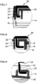
- the fixing part 100 On its underside 120 facing the first housing half-shell 38, the fixing part 100 carries a plurality of first holding elements 122 which are arranged at a distance from one another and are each configured in an L-shape. In the fixed position of the fixing part 100, the first holding elements 122 each engage behind a rib-shaped or L-shaped second holding element 124, which is arranged on a bottom wall 128 of the receptacle 104. This is in particular from the Figures 7 to 9 clearly.
- the bottom wall 128 is formed by the first housing half-shell 38 and has a depression 130 in the middle, which is bridged by the cross brace 118 in the region of the rear end section 50 of the suction channel 48 .
- the latching hook 114 first enters the recess 130 .
- the fixing part 100 can then be pushed backwards along the bottom wall 128, with the first holding elements 122 arranged on the underside 120 of the fixing part 100 each plunging into a guide opening 132 in the end wall 74, which is adjoined by a second holding element 124 in each case.
- the fixing part 100 can then be pushed back along the bottom wall 128 until the latching hook 114 snaps into the latching receptacle 116 of the first housing half-shell 38 and at the same time the cover plate 110 of the fixing part 100 comes to rest on the receptacle edges 106 and 108.
- the first holding elements 122 in combination with the second holding elements 124 form a linear guide for the fixing part 100 so that the fixing part 100 can be displaced along the bottom wall 128 without the risk of the fixing part 100 tilting.
- the first holding elements 122 which are L-shaped in cross section, engage behind the second holding elements 124 when the fastening part 100 is displaced along the bottom wall 128, with the fastening part 100 being subjected to a holding force by the first housing half-shell 38 via the second holding elements 124 and the first holding elements 122.
- the fixing part 100 is pressed against the first half-shell 38 of the housing becomes.
- the retaining strip 102 is pressed against the rear end section 50 of the peel-off lip.
- the replaceable pull-off lip 58 can be fixed on the housing 36 of the suction nozzle 12 with the aid of the fixing part 100 .
- the fixing part 100 assumes its fixing position, in which the holding strip 102 of the fixing part 100 covers the rear end section 70 of the replaceable pull-off lip 58 so that the pull-off lip 58 is fixed to the housing 36 .
- the interaction of the holding strip 102 with the rear end section 70 of the pull-off lip 58 and the supporting edge 72 in the fixed position is in figure 14 illustrated.
- the user can - after separating the suction nozzle 12 from the base body 14 of the hard surface suction device - push the latching hook 114 out of the latching receptacle 116 and then insert the fixing part 100 into the in figure 14 Move forwards in the direction illustrated by the arrow 138, so that the first holding elements 122 emerge from the guide openings 132 and the fixing part 100 can then be completely separated from the housing 36 of the suction nozzle 12. This is in figure 15 illustrated. The user can then easily remove the pull-off lip 58 from the supporting edge 72 of the first housing half-shell 38, as is shown in figure 16 is illustrated.
- a pull-off lip 58 is fixed to the housing 36 in the reverse order, in which the pull-off lip 58 is first positioned with its rear end section 70 on the supporting edge 72 and then the fixing part 100 is connected to the housing 36 by first moving the latching hook 114 to the central Recess 130 of the bottom wall 128 is used and then the fixing part is moved along the bottom wall 128 in its fixing position.
- the suction nozzle 12 can be plugged into the base body 14 of the hard surface suction device 10 .
- the rear end section 50 of the suction channel 48 can be inserted into the inlet channel 56 of the basic housing 16 .
- a further latching hook 134 on the underside 136 of the second housing half-shell facing away from the first housing half-shell 38 40 is arranged, the suction nozzle 12 can be latched to the base housing 16.
- the additional latching hook 136 can engage in an opening (not shown in the drawing) in the base housing 16, and to remove the suction nozzle 12 from the base body 16, the user can actuate the additional latching hook 136 so that the latched connection between the suction nozzle 12 and the base housing 16 is released .
Landscapes
- Nozzles For Electric Vacuum Cleaners (AREA)
Claims (15)
- Buse d'aspiration pour un appareil d'aspiration portable pour surfaces dures destiné à retirer et aspirer un liquide d'une surface dure, en particulier d'une vitre de fenêtre, comprenant un logement (36) qui présente sur une face frontale de logement (44) une ouverture d'aspiration (46) à laquelle se raccorde un canal d'aspiration (48) qui peut être raccordé à une source de dépression, et comprenant une lèvre de retrait (58) déformable élastiquement, qui est montée de manière à pouvoir être remplacée sur la face frontale de logemen( 44), la buse d'aspiration (12) présentant une partie de fixation (100) pouvant être déplacé en va-et-vient par rapport au logement (36) entre une position de fixation et une position de libération, la lèvre de retrait (48) pouvant être fixée au logement (36) dans la position de fixation de la partie de fixation (100) à l'aide de la partie de fixation (100), et pouvant être séparée du logement (36) dans la position de libération de la partie de fixation (100), caractérisée en ce que la partie de fixation (100) peut être déplacée le long d'une face extérieure (90) du logement (36) .
- Buse d'aspiration selon la revendication 1, caractérisée en ce que le logement (36) présente un bord d'appui (72) sur lequel une section d'extrémité arrière (70) de la lèvre de retrait (58) peut être positionnée, et en ce que la partie de fixation (100) présente une bande de retenue (102) qui peut être positionnée sur la section d'extrémité arrière (70) de la lèvre de retrait (58) dans la position de fixation de la partie de fixation (100), de préférence en ce que la bande de retenue (102) s'étend dans position de fixation de la partie de fixation (100) à partir d'un premier bord latéral (86) de la lèvre de retrait (58) jusqu'à un second bord latéral (88) de la lèvre de retrait (58).
- Buse d'aspiration selon la revendication 2, caractérisée en ce que la section d'extrémité arrière (70) de la lèvre de retrait (58) et le bord d'appui (72) du logement (36) présentent des saillies (78, 84) orientées angulairement par rapport à un axe longitudinal (80) de la buse d'aspiration (12), qui viennent en prise l'une dans l'autre.
- Buse d'aspiration selon l'une quelconque des revendications précédentes, caractérisée en ce que la partie de fixation (100) peut être reliée de manière amovible au logement (36), de préférence en ce que la partie de fixation (100) peut être encliquetée de manière amovible avec le logement (36).
- Buse d'aspiration selon l'une quelconque des revendications précédentes, caractérisée en ce que la partie de fixation (100) présente au moins un premier élément d'encliquetage (114) qui, dans la position de fixation, vient en prise derrière un second élément d'encliquetage (118) agencé sur le logement (36).
- Buse d'aspiration selon la revendication 5, caractérisée en ce que le au moins un premier élément d'encliquetage (114) est agencé sur une face arrière (112) de la partie de fixation (100) et en ce que le au moins un second élément d'encliquetage (118) est agencé sur une section d'extrémité (50) du canal d'aspiration (48) faisant saillie à partir d'une face arrière de logement (52) du logement (36).
- Buse d'aspiration selon l'une quelconque des revendications précédentes, caractérisée en ce que la partie de fixation (100) peut être séparée du logement (36).
- Buse d'aspiration selon l'une quelconque des revendications précédentes, caractérisée en ce que la partie de fixation (100), dans la position de fixation, recouvre au moins en partie une face extérieure (90) du logement (36).
- Buse d'aspiration selon l'une quelconque des revendications précédentes, caractérisée en ce que le logement (36) présente une cavité (104) sur une face extérieure (90), dans laquelle la partie de fixation (100) peut être insérée.
- Buse d'aspiration selon l'une quelconque des revendications précédentes, caractérisée en ce que la partie de fixation (100) peut être sollicitée par le logement (36) dans la position de fixation avec une force de retenue en direction du logement (36), de préférence en ce que la partie de fixation (100) présente au moins un premier élément de retenue (122) qui peut être sollicité dans la position de fixation de la partie de fixation (100) par un second élément de retenue (124) agencé de manière fixe sur le logement (36) avec une force de retenue en direction du logement (36).
- Buse d'aspiration selon la revendication 10, caractérisée en ce que le au moins un premier élément de retenue (122) vient en prise derrière un second élément de retenue (124) dans la position de fixation de la partie de fixation (100).
- Buse d'aspiration selon la revendication 10 ou 11, caractérisée en ce que le au moins un premier élément de retenue forme conjointement, en combinaison avec un second élément de retenue (124), un guidage linéaire pour déplacer la partie de fixation (100) par rapport au logement (36).
- Buse d'aspiration selon la revendication 10, 11 ou 12, caractérisée en ce que les premiers et/ou seconds éléments de retenue (122, 124) sont réalisés en forme de nervures ou en forme de L.
- Buse d'aspiration selon l'une quelconque des revendications 10 à 13, caractérisée en ce que le logement (36) présente des ouvertures de guidage (132) dans lesquelles peut être introduit un premier élément de retenue (122), un second élément de retenue (124) étant agencé à l'intérieur du logement (36) en alignement avec les ouvertures de guidage (132), de préférence en ce que les ouvertures de guidage (132) sont agencées sur une paroi frontale (74) du logement (36), à la face extérieure de laquelle se raccorde la lèvre de retrait (58).
- Appareil d'aspiration portable pour surfaces dures destiné à retirer et aspirer un liquide d'une surface dure, en particulier d'une vitre de fenêtre, comprenant une buse d'aspiration (12) selon l'une quelconque des revendications précédentes, et un groupe d'aspiration (20) qui est en liaison d'écoulement de flux avec la buse d'aspiration (12) pour aspirer un mélange liquide-air de la surface dure, et un dispositif de séparation (32) qui est agencé dans le trajet d'écoulement entre la buse d'aspiration (12) et le groupe d'aspiration (20) pour séparer le liquide à partir du mélange liquide-air aspiré, et un réservoir de liquide (34) pour recevoir le liquide séparé.
Priority Applications (1)
| Application Number | Priority Date | Filing Date | Title |
|---|---|---|---|
| PL18707365.5T PL3758568T3 (pl) | 2018-02-26 | 2018-02-26 | Dysza ssąca i przenośne urządzenie odsysające do twardych powierzchni |
Applications Claiming Priority (1)
| Application Number | Priority Date | Filing Date | Title |
|---|---|---|---|
| PCT/EP2018/054675 WO2019161933A1 (fr) | 2018-02-26 | 2018-02-26 | Buse d'aspiration et appareil d'aspiration portable pour surfaces dures |
Publications (3)
| Publication Number | Publication Date |
|---|---|
| EP3758568A1 EP3758568A1 (fr) | 2021-01-06 |
| EP3758568B1 true EP3758568B1 (fr) | 2023-08-23 |
| EP3758568C0 EP3758568C0 (fr) | 2023-08-23 |
Family
ID=61283244
Family Applications (1)
| Application Number | Title | Priority Date | Filing Date |
|---|---|---|---|
| EP18707365.5A Active EP3758568B1 (fr) | 2018-02-26 | 2018-02-26 | Buse d'aspiration et appareil d'aspiration portable pour surfaces dures |
Country Status (4)
| Country | Link |
|---|---|
| EP (1) | EP3758568B1 (fr) |
| CN (1) | CN111683574A (fr) |
| PL (1) | PL3758568T3 (fr) |
| WO (1) | WO2019161933A1 (fr) |
Citations (2)
| Publication number | Priority date | Publication date | Assignee | Title |
|---|---|---|---|---|
| DE202008018112U1 (de) * | 2008-01-11 | 2011-08-01 | Alfred Kärcher Gmbh & Co. Kg | Saugdüse |
| EP3195780B1 (fr) * | 2016-01-22 | 2018-05-16 | Leifheit AG | Buse d'aspiration |
Family Cites Families (5)
| Publication number | Priority date | Publication date | Assignee | Title |
|---|---|---|---|---|
| CN203042128U (zh) * | 2013-02-05 | 2013-07-10 | 朱厚林 | 一种改进的硬质表面的吸水器 |
| CN106793897B (zh) * | 2014-08-29 | 2020-06-12 | 阿尔弗雷德·卡赫欧洲两合公司 | 抽吸嘴和硬质面抽吸设备 |
| CN105327868B (zh) * | 2015-11-10 | 2017-10-31 | 朱厚林 | 一种硬质表面吸水清洁器 |
| CN205458475U (zh) * | 2016-01-18 | 2016-08-17 | 朱厚林 | 一种硬质表面吸水清洁器的刮头 |
| CN107212799A (zh) * | 2016-03-22 | 2017-09-29 | 宁波永冠电器有限公司 | 一种多功能吸尘清洁一体机 |
-
2018
- 2018-02-26 CN CN201880088498.8A patent/CN111683574A/zh active Pending
- 2018-02-26 WO PCT/EP2018/054675 patent/WO2019161933A1/fr not_active Ceased
- 2018-02-26 PL PL18707365.5T patent/PL3758568T3/pl unknown
- 2018-02-26 EP EP18707365.5A patent/EP3758568B1/fr active Active
Patent Citations (2)
| Publication number | Priority date | Publication date | Assignee | Title |
|---|---|---|---|---|
| DE202008018112U1 (de) * | 2008-01-11 | 2011-08-01 | Alfred Kärcher Gmbh & Co. Kg | Saugdüse |
| EP3195780B1 (fr) * | 2016-01-22 | 2018-05-16 | Leifheit AG | Buse d'aspiration |
Also Published As
| Publication number | Publication date |
|---|---|
| PL3758568T3 (pl) | 2024-03-04 |
| EP3758568A1 (fr) | 2021-01-06 |
| CN111683574A (zh) | 2020-09-18 |
| WO2019161933A1 (fr) | 2019-08-29 |
| EP3758568C0 (fr) | 2023-08-23 |
Similar Documents
| Publication | Publication Date | Title |
|---|---|---|
| EP3021727B1 (fr) | Appareil de nettoyage de surfaces dures portable | |
| EP3393319B1 (fr) | Buse d'aspiration pour un appareil de nettoyage de surface dures et appareil de nettoyage de surfaces dures comportant une telle buse d'aspiration | |
| EP2638839B1 (fr) | Buse d'aspiration avec raclettes | |
| EP3021722B1 (fr) | Appareil de nettoyage de surfaces dures portable | |
| EP3746233B1 (fr) | Appareil de nettoyage haute pression | |
| EP3021723B2 (fr) | Appareil de nettoyage de surfaces dures portable | |
| EP3681360B1 (fr) | Appareil de nettoyage des surfaces | |
| WO2014032712A1 (fr) | Système d'aspiration de surfaces équipé d'un dispositif d'allonge | |
| EP3185741A1 (fr) | Buse d'aspiration et appareil d'aspiration de surfaces dures | |
| WO2017108088A1 (fr) | Buse d'aspiration pour appareil de nettoyage de surface dure et appareil de nettoyage de surface dure équipé d'une telle buse | |
| DE3136401C2 (de) | Mehrzweck-Reinigungsgerät | |
| EP3518720B2 (fr) | Buse d'aspiration et appareil d'aspiration de surfaces dures | |
| WO2016162087A1 (fr) | Pompe submersible à préfiltre | |
| EP3758568B1 (fr) | Buse d'aspiration et appareil d'aspiration portable pour surfaces dures | |
| EP3681361B1 (fr) | Appareil de nettoyage de surfaces | |
| EP3393322B1 (fr) | Appareil portable de nettoyage de surfaces dures | |
| EP3021724B1 (fr) | Appareil de nettoyage de surfaces dures portable | |
| EP3006636B1 (fr) | Évacuation murale avec pompe | |
| DE202014011047U1 (de) | Saugdüse und Hartflächenabsauggerät | |
| EP0286692B1 (fr) | Appareil de nettoyage de surfaces planes | |
| DE10056928B4 (de) | Vorrichtung zur Reinigung von wiederholt verwendeten Werkzeugen | |
| DE102013011004A1 (de) | Vorrichtung zur Reinigung glatter Oberflächen |
Legal Events
| Date | Code | Title | Description |
|---|---|---|---|
| STAA | Information on the status of an ep patent application or granted ep patent |
Free format text: STATUS: UNKNOWN |
|
| STAA | Information on the status of an ep patent application or granted ep patent |
Free format text: STATUS: THE INTERNATIONAL PUBLICATION HAS BEEN MADE |
|
| PUAI | Public reference made under article 153(3) epc to a published international application that has entered the european phase |
Free format text: ORIGINAL CODE: 0009012 |
|
| STAA | Information on the status of an ep patent application or granted ep patent |
Free format text: STATUS: REQUEST FOR EXAMINATION WAS MADE |
|
| 17P | Request for examination filed |
Effective date: 20200716 |
|
| AK | Designated contracting states |
Kind code of ref document: A1 Designated state(s): AL AT BE BG CH CY CZ DE DK EE ES FI FR GB GR HR HU IE IS IT LI LT LU LV MC MK MT NL NO PL PT RO RS SE SI SK SM TR |
|
| AX | Request for extension of the european patent |
Extension state: BA ME |
|
| DAV | Request for validation of the european patent (deleted) | ||
| DAX | Request for extension of the european patent (deleted) | ||
| GRAP | Despatch of communication of intention to grant a patent |
Free format text: ORIGINAL CODE: EPIDOSNIGR1 |
|
| STAA | Information on the status of an ep patent application or granted ep patent |
Free format text: STATUS: GRANT OF PATENT IS INTENDED |
|
| INTG | Intention to grant announced |
Effective date: 20230322 |
|
| P01 | Opt-out of the competence of the unified patent court (upc) registered |
Effective date: 20230521 |
|
| GRAS | Grant fee paid |
Free format text: ORIGINAL CODE: EPIDOSNIGR3 |
|
| GRAA | (expected) grant |
Free format text: ORIGINAL CODE: 0009210 |
|
| STAA | Information on the status of an ep patent application or granted ep patent |
Free format text: STATUS: THE PATENT HAS BEEN GRANTED |
|
| AK | Designated contracting states |
Kind code of ref document: B1 Designated state(s): AL AT BE BG CH CY CZ DE DK EE ES FI FR GB GR HR HU IE IS IT LI LT LU LV MC MK MT NL NO PL PT RO RS SE SI SK SM TR |
|
| REG | Reference to a national code |
Ref country code: GB Ref legal event code: FG4D Free format text: NOT ENGLISH |
|
| REG | Reference to a national code |
Ref country code: CH Ref legal event code: EP |
|
| REG | Reference to a national code |
Ref country code: DE Ref legal event code: R096 Ref document number: 502018013041 Country of ref document: DE |
|
| REG | Reference to a national code |
Ref country code: IE Ref legal event code: FG4D Free format text: LANGUAGE OF EP DOCUMENT: GERMAN |
|
| U01 | Request for unitary effect filed |
Effective date: 20230920 |
|
| U07 | Unitary effect registered |
Designated state(s): AT BE BG DE DK EE FI FR IT LT LU LV MT NL PT SE SI Effective date: 20230926 |
|
| P04 | Withdrawal of opt-out of the competence of the unified patent court (upc) registered |
Effective date: 20230922 |
|
| PG25 | Lapsed in a contracting state [announced via postgrant information from national office to epo] |
Ref country code: GR Free format text: LAPSE BECAUSE OF FAILURE TO SUBMIT A TRANSLATION OF THE DESCRIPTION OR TO PAY THE FEE WITHIN THE PRESCRIBED TIME-LIMIT Effective date: 20231124 |
|
| PG25 | Lapsed in a contracting state [announced via postgrant information from national office to epo] |
Ref country code: IS Free format text: LAPSE BECAUSE OF FAILURE TO SUBMIT A TRANSLATION OF THE DESCRIPTION OR TO PAY THE FEE WITHIN THE PRESCRIBED TIME-LIMIT Effective date: 20231223 |
|
| PG25 | Lapsed in a contracting state [announced via postgrant information from national office to epo] |
Ref country code: RS Free format text: LAPSE BECAUSE OF FAILURE TO SUBMIT A TRANSLATION OF THE DESCRIPTION OR TO PAY THE FEE WITHIN THE PRESCRIBED TIME-LIMIT Effective date: 20230823 Ref country code: NO Free format text: LAPSE BECAUSE OF FAILURE TO SUBMIT A TRANSLATION OF THE DESCRIPTION OR TO PAY THE FEE WITHIN THE PRESCRIBED TIME-LIMIT Effective date: 20231123 Ref country code: IS Free format text: LAPSE BECAUSE OF FAILURE TO SUBMIT A TRANSLATION OF THE DESCRIPTION OR TO PAY THE FEE WITHIN THE PRESCRIBED TIME-LIMIT Effective date: 20231223 Ref country code: HR Free format text: LAPSE BECAUSE OF FAILURE TO SUBMIT A TRANSLATION OF THE DESCRIPTION OR TO PAY THE FEE WITHIN THE PRESCRIBED TIME-LIMIT Effective date: 20230823 Ref country code: GR Free format text: LAPSE BECAUSE OF FAILURE TO SUBMIT A TRANSLATION OF THE DESCRIPTION OR TO PAY THE FEE WITHIN THE PRESCRIBED TIME-LIMIT Effective date: 20231124 |
|
| U20 | Renewal fee for the european patent with unitary effect paid |
Year of fee payment: 7 Effective date: 20240226 |
|
| PG25 | Lapsed in a contracting state [announced via postgrant information from national office to epo] |
Ref country code: ES Free format text: LAPSE BECAUSE OF FAILURE TO SUBMIT A TRANSLATION OF THE DESCRIPTION OR TO PAY THE FEE WITHIN THE PRESCRIBED TIME-LIMIT Effective date: 20230823 |
|
| PG25 | Lapsed in a contracting state [announced via postgrant information from national office to epo] |
Ref country code: SM Free format text: LAPSE BECAUSE OF FAILURE TO SUBMIT A TRANSLATION OF THE DESCRIPTION OR TO PAY THE FEE WITHIN THE PRESCRIBED TIME-LIMIT Effective date: 20230823 Ref country code: RO Free format text: LAPSE BECAUSE OF FAILURE TO SUBMIT A TRANSLATION OF THE DESCRIPTION OR TO PAY THE FEE WITHIN THE PRESCRIBED TIME-LIMIT Effective date: 20230823 Ref country code: ES Free format text: LAPSE BECAUSE OF FAILURE TO SUBMIT A TRANSLATION OF THE DESCRIPTION OR TO PAY THE FEE WITHIN THE PRESCRIBED TIME-LIMIT Effective date: 20230823 Ref country code: CZ Free format text: LAPSE BECAUSE OF FAILURE TO SUBMIT A TRANSLATION OF THE DESCRIPTION OR TO PAY THE FEE WITHIN THE PRESCRIBED TIME-LIMIT Effective date: 20230823 Ref country code: SK Free format text: LAPSE BECAUSE OF FAILURE TO SUBMIT A TRANSLATION OF THE DESCRIPTION OR TO PAY THE FEE WITHIN THE PRESCRIBED TIME-LIMIT Effective date: 20230823 |
|
| REG | Reference to a national code |
Ref country code: DE Ref legal event code: R097 Ref document number: 502018013041 Country of ref document: DE |
|
| PLBE | No opposition filed within time limit |
Free format text: ORIGINAL CODE: 0009261 |
|
| STAA | Information on the status of an ep patent application or granted ep patent |
Free format text: STATUS: NO OPPOSITION FILED WITHIN TIME LIMIT |
|
| 26N | No opposition filed |
Effective date: 20240524 |
|
| PG25 | Lapsed in a contracting state [announced via postgrant information from national office to epo] |
Ref country code: MC Free format text: LAPSE BECAUSE OF FAILURE TO SUBMIT A TRANSLATION OF THE DESCRIPTION OR TO PAY THE FEE WITHIN THE PRESCRIBED TIME-LIMIT Effective date: 20230823 |
|
| REG | Reference to a national code |
Ref country code: CH Ref legal event code: PL |
|
| PG25 | Lapsed in a contracting state [announced via postgrant information from national office to epo] |
Ref country code: CH Free format text: LAPSE BECAUSE OF NON-PAYMENT OF DUE FEES Effective date: 20240229 |
|
| PG25 | Lapsed in a contracting state [announced via postgrant information from national office to epo] |
Ref country code: CH Free format text: LAPSE BECAUSE OF NON-PAYMENT OF DUE FEES Effective date: 20240229 |
|
| P05 | Withdrawal of opt-out of the competence of the unified patent court (upc) changed |
Free format text: CASE NUMBER: APP_574607/2023 Effective date: 20230926 |
|
| PG25 | Lapsed in a contracting state [announced via postgrant information from national office to epo] |
Ref country code: IE Free format text: LAPSE BECAUSE OF NON-PAYMENT OF DUE FEES Effective date: 20240226 |
|
| PG25 | Lapsed in a contracting state [announced via postgrant information from national office to epo] |
Ref country code: IE Free format text: LAPSE BECAUSE OF NON-PAYMENT OF DUE FEES Effective date: 20240226 |
|
| U20 | Renewal fee for the european patent with unitary effect paid |
Year of fee payment: 8 Effective date: 20250224 |
|
| PG25 | Lapsed in a contracting state [announced via postgrant information from national office to epo] |
Ref country code: CY Free format text: LAPSE BECAUSE OF FAILURE TO SUBMIT A TRANSLATION OF THE DESCRIPTION OR TO PAY THE FEE WITHIN THE PRESCRIBED TIME-LIMIT; INVALID AB INITIO Effective date: 20180226 |
|
| PG25 | Lapsed in a contracting state [announced via postgrant information from national office to epo] |
Ref country code: HU Free format text: LAPSE BECAUSE OF FAILURE TO SUBMIT A TRANSLATION OF THE DESCRIPTION OR TO PAY THE FEE WITHIN THE PRESCRIBED TIME-LIMIT; INVALID AB INITIO Effective date: 20180226 |
|
| PG25 | Lapsed in a contracting state [announced via postgrant information from national office to epo] |
Ref country code: TR Free format text: LAPSE BECAUSE OF FAILURE TO SUBMIT A TRANSLATION OF THE DESCRIPTION OR TO PAY THE FEE WITHIN THE PRESCRIBED TIME-LIMIT Effective date: 20230823 |
|
| U20 | Renewal fee for the european patent with unitary effect paid |
Year of fee payment: 9 Effective date: 20260204 |
|
| PGFP | Annual fee paid to national office [announced via postgrant information from national office to epo] |
Ref country code: GB Payment date: 20260119 Year of fee payment: 9 |
|
| PGFP | Annual fee paid to national office [announced via postgrant information from national office to epo] |
Ref country code: PL Payment date: 20260127 Year of fee payment: 9 |