EP3760131A1 - Dispositif de traction de ballonnet et son procédé de fabrication - Google Patents
Dispositif de traction de ballonnet et son procédé de fabrication Download PDFInfo
- Publication number
- EP3760131A1 EP3760131A1 EP18907619.3A EP18907619A EP3760131A1 EP 3760131 A1 EP3760131 A1 EP 3760131A1 EP 18907619 A EP18907619 A EP 18907619A EP 3760131 A1 EP3760131 A1 EP 3760131A1
- Authority
- EP
- European Patent Office
- Prior art keywords
- balloon
- core tube
- pulling device
- tube
- manufacturing
- Prior art date
- Legal status (The legal status is an assumption and is not a legal conclusion. Google has not performed a legal analysis and makes no representation as to the accuracy of the status listed.)
- Pending
Links
- 238000004519 manufacturing process Methods 0.000 title claims description 12
- 239000012530 fluid Substances 0.000 claims abstract description 18
- 239000000463 material Substances 0.000 claims description 30
- 238000001816 cooling Methods 0.000 claims description 6
- 238000007599 discharging Methods 0.000 claims description 6
- 238000003466 welding Methods 0.000 claims description 5
- 238000004026 adhesive bonding Methods 0.000 claims description 4
- 238000004080 punching Methods 0.000 claims 2
- 238000005452 bending Methods 0.000 description 10
- 239000002184 metal Substances 0.000 description 6
- 238000000465 moulding Methods 0.000 description 6
- 238000010586 diagram Methods 0.000 description 5
- 238000001356 surgical procedure Methods 0.000 description 5
- XLYOFNOQVPJJNP-UHFFFAOYSA-N water Substances O XLYOFNOQVPJJNP-UHFFFAOYSA-N 0.000 description 5
- 239000002861 polymer material Substances 0.000 description 4
- 229920001169 thermoplastic Polymers 0.000 description 4
- 238000000034 method Methods 0.000 description 3
- 238000002360 preparation method Methods 0.000 description 3
- 238000003801 milling Methods 0.000 description 2
- 238000011477 surgical intervention Methods 0.000 description 2
- 0 C*C*IN[N+]S Chemical compound C*C*IN[N+]S 0.000 description 1
- 208000000860 Compassion Fatigue Diseases 0.000 description 1
- 208000002847 Surgical Wound Diseases 0.000 description 1
- 210000004556 brain Anatomy 0.000 description 1
- 238000013130 cardiovascular surgery Methods 0.000 description 1
- 238000004891 communication Methods 0.000 description 1
- 230000008602 contraction Effects 0.000 description 1
- 238000006073 displacement reaction Methods 0.000 description 1
- 210000003238 esophagus Anatomy 0.000 description 1
- 229920002457 flexible plastic Polymers 0.000 description 1
- 238000011902 gastrointestinal surgery Methods 0.000 description 1
- 210000001035 gastrointestinal tract Anatomy 0.000 description 1
- 239000003292 glue Substances 0.000 description 1
- 238000003384 imaging method Methods 0.000 description 1
- 238000002357 laparoscopic surgery Methods 0.000 description 1
- 239000007788 liquid Substances 0.000 description 1
- 238000002844 melting Methods 0.000 description 1
- 230000008018 melting Effects 0.000 description 1
- 239000007769 metal material Substances 0.000 description 1
- 238000012986 modification Methods 0.000 description 1
- 230000004048 modification Effects 0.000 description 1
- 210000000056 organ Anatomy 0.000 description 1
- 239000004033 plastic Substances 0.000 description 1
- 229920003023 plastic Polymers 0.000 description 1
- 210000003708 urethra Anatomy 0.000 description 1
- 210000003932 urinary bladder Anatomy 0.000 description 1
- 208000014001 urinary system disease Diseases 0.000 description 1
- 210000001215 vagina Anatomy 0.000 description 1
Images


Classifications
-
- A—HUMAN NECESSITIES
- A61—MEDICAL OR VETERINARY SCIENCE; HYGIENE
- A61B—DIAGNOSIS; SURGERY; IDENTIFICATION
- A61B17/00—Surgical instruments, devices or methods
- A61B17/02—Surgical instruments, devices or methods for holding wounds open, e.g. retractors; Tractors
- A61B17/0218—Surgical instruments, devices or methods for holding wounds open, e.g. retractors; Tractors for minimally invasive surgery
-
- A—HUMAN NECESSITIES
- A61—MEDICAL OR VETERINARY SCIENCE; HYGIENE
- A61B—DIAGNOSIS; SURGERY; IDENTIFICATION
- A61B17/00—Surgical instruments, devices or methods
- A61B17/02—Surgical instruments, devices or methods for holding wounds open, e.g. retractors; Tractors
-
- A—HUMAN NECESSITIES
- A61—MEDICAL OR VETERINARY SCIENCE; HYGIENE
- A61M—DEVICES FOR INTRODUCING MEDIA INTO, OR ONTO, THE BODY; DEVICES FOR TRANSDUCING BODY MEDIA OR FOR TAKING MEDIA FROM THE BODY; DEVICES FOR PRODUCING OR ENDING SLEEP OR STUPOR
- A61M25/00—Catheters; Hollow probes
- A61M25/10—Balloon catheters
- A61M25/1011—Multiple balloon catheters
-
- A—HUMAN NECESSITIES
- A61—MEDICAL OR VETERINARY SCIENCE; HYGIENE
- A61M—DEVICES FOR INTRODUCING MEDIA INTO, OR ONTO, THE BODY; DEVICES FOR TRANSDUCING BODY MEDIA OR FOR TAKING MEDIA FROM THE BODY; DEVICES FOR PRODUCING OR ENDING SLEEP OR STUPOR
- A61M29/00—Dilators with or without means for introducing media, e.g. remedies
- A61M29/02—Dilators made of swellable material
-
- B—PERFORMING OPERATIONS; TRANSPORTING
- B29—WORKING OF PLASTICS; WORKING OF SUBSTANCES IN A PLASTIC STATE IN GENERAL
- B29C—SHAPING OR JOINING OF PLASTICS; SHAPING OF MATERIAL IN A PLASTIC STATE, NOT OTHERWISE PROVIDED FOR; AFTER-TREATMENT OF THE SHAPED PRODUCTS, e.g. REPAIRING
- B29C49/00—Blow-moulding, i.e. blowing a preform or parison to a desired shape within a mould; Apparatus therefor
- B29C49/02—Combined blow-moulding and manufacture of the preform or the parison
- B29C49/04—Extrusion blow-moulding
-
- A—HUMAN NECESSITIES
- A61—MEDICAL OR VETERINARY SCIENCE; HYGIENE
- A61B—DIAGNOSIS; SURGERY; IDENTIFICATION
- A61B17/00—Surgical instruments, devices or methods
- A61B2017/00526—Methods of manufacturing
-
- A—HUMAN NECESSITIES
- A61—MEDICAL OR VETERINARY SCIENCE; HYGIENE
- A61B—DIAGNOSIS; SURGERY; IDENTIFICATION
- A61B17/00—Surgical instruments, devices or methods
- A61B2017/00535—Surgical instruments, devices or methods pneumatically or hydraulically operated
- A61B2017/00557—Surgical instruments, devices or methods pneumatically or hydraulically operated inflatable
-
- A—HUMAN NECESSITIES
- A61—MEDICAL OR VETERINARY SCIENCE; HYGIENE
- A61B—DIAGNOSIS; SURGERY; IDENTIFICATION
- A61B17/00—Surgical instruments, devices or methods
- A61B17/22—Implements for squeezing-off ulcers or the like on inner organs of the body; Implements for scraping-out cavities of body organs, e.g. bones; for invasive removal or destruction of calculus using mechanical vibrations; for removing obstructions in blood vessels, not otherwise provided for
- A61B2017/22051—Implements for squeezing-off ulcers or the like on inner organs of the body; Implements for scraping-out cavities of body organs, e.g. bones; for invasive removal or destruction of calculus using mechanical vibrations; for removing obstructions in blood vessels, not otherwise provided for with an inflatable part, e.g. balloon, for positioning, blocking, or immobilisation
- A61B2017/22055—Implements for squeezing-off ulcers or the like on inner organs of the body; Implements for scraping-out cavities of body organs, e.g. bones; for invasive removal or destruction of calculus using mechanical vibrations; for removing obstructions in blood vessels, not otherwise provided for with an inflatable part, e.g. balloon, for positioning, blocking, or immobilisation with three or more balloons
-
- A—HUMAN NECESSITIES
- A61—MEDICAL OR VETERINARY SCIENCE; HYGIENE
- A61M—DEVICES FOR INTRODUCING MEDIA INTO, OR ONTO, THE BODY; DEVICES FOR TRANSDUCING BODY MEDIA OR FOR TAKING MEDIA FROM THE BODY; DEVICES FOR PRODUCING OR ENDING SLEEP OR STUPOR
- A61M25/00—Catheters; Hollow probes
- A61M2025/0008—Catheters; Hollow probes having visible markings on its surface, i.e. visible to the naked eye, for any purpose, e.g. insertion depth markers, rotational markers or identification of type
-
- A—HUMAN NECESSITIES
- A61—MEDICAL OR VETERINARY SCIENCE; HYGIENE
- A61M—DEVICES FOR INTRODUCING MEDIA INTO, OR ONTO, THE BODY; DEVICES FOR TRANSDUCING BODY MEDIA OR FOR TAKING MEDIA FROM THE BODY; DEVICES FOR PRODUCING OR ENDING SLEEP OR STUPOR
- A61M25/00—Catheters; Hollow probes
- A61M25/0009—Making of catheters or other medical or surgical tubes
Definitions
- the present invention relates to the field of medical equipment, in particular to a balloon pulling device and a manufacturing method thereof.
- Retractors also known as pull hooks, are used to retract tissues, reveal the scope of surgery, and facilitate exploration and operation. They can be divided into hand-held retractors and automatic retractors. There are various specifications of different shapes and sizes, and the appropriate retractor can be selected according to the needs of the operation.
- the traditional retractor requires a large operating space, which requires a large surgical wound.
- traditional retractors are mostly made of metal and have sharp ends, which are likely to cause secondary trauma to patients and damage important organs.
- the catheter retractor is used for tissue retraction during surgery and the product can complete the retraction operation through natural cavity intervention or open surgical intervention.
- Surgery includes, but is not limited to, various types of laparoscopic surgery, cardiovascular surgery, brain surgery, gastrointestinal surgery, urinary disease surgery, etc.
- the tissues to be retracted include but are not limited to gastrointestinal tract, esophagus, airway, urethra, vagina, bladder, etc.
- the purpose of retraction includes but is not limited to protecting specific tissues and removing specific tissues to facilitate surgical operations.
- a balloon catheter retractor as shown in Figure 1 comprising: a catheter 5 with an air valve at one end, a balloon 4 arranged on the periphery of the catheter 5, one or more cavities in the catheter, and the catheter part of the tube is inflated or deflated, and the balloon 4 will bend to one side when inflated.
- the material of the balloon 4 is non-compliant, and the two ends 3 are sealed on the catheter 5 by laser welding.
- the curved balloon shown in Figure 1 uses a single balloon, which places higher requirements on the material and degree of curvature of the balloon. Only by accurately calculating and testing the balloon material can the retraction of a specific operation be achieved. Distance requirements. This brings difficulties to the preparation of such curved balloons and puts forward higher technical requirements. In some specific operations, the curvature of a single balloon may not achieve the required retraction distance.
- the purpose of the present invention is to provide a curved balloon for natural channel intervention or open surgical intervention to complete the retraction operation based on the above-mentioned problems, which solves the problem that the current catheter retractor has complex structure, inconvenient operation, and large product diameter and cannot pass through.
- the narrow, complicated structure of the cavity, the inability to accurately control the pulling force, the low reliability and other problems, the present invention realizes a simple and reliable balloon pulling device that can realize a larger distance and can be precisely adjusted.
- the present invention provides a balloon pulling device, which includes a core tube and a balloon part.
- the core tube part can inflate and release fluid to the balloon part.
- the balloon part is characterized in that the balloon part includes several expansion sections. The inflation section is larger than the rest of the balloon after being filled with fluid, so that the entire balloon is bent.
- the core tube is flexible and has a plurality of long strips of cavities therein. There is at least one hole on the surface of the core tube, or there is a corresponding hole for each expansion section, encapsulated or attached to the core tube.
- the axis of the balloon is on one side of the axis of the core tube.
- the core tube can be a number of independent core tubes, each core tube individually or separately controls the inflation or charging and discharging of several balloon inflation or expansion segments; or it can also be a multi-lumen tube, each tube individually controlling the inflation or charging and discharging of several balloon inflation or expansion segments.
- each balloon has multiple expansion sections, so that each balloon can be individually controlled to bend, or each balloon can individually control the bending.
- the two ends of the balloon are connected with a wire-like material with low ductility.
- the recommended parameters of the balloon can be any one or several of the following groups:
- the length of the expanded section of the balloon is greater than its outer diameter in the unexpanded state.
- the adjacent intervals between the inflation or expanded segments of the balloon are less than 0.2 times the length of the inflation or expanded segments.
- the present invention also provides a method for manufacturing a balloon pulling device, which includes the following steps: using a splicing mold or die to make the material form a balloon on the balloon forming machine; after cooling, the mold is removed and the balloon is taken out; The cavity core tube is bored and punched in the core tube; the balloon is placed in a preset or predetermined position, and the balloon is fixed on the core tube by welding or glue bonding.
- the mold is divided into two parts, and the shape of the inner or internal cavity after the splicing of the two petal molds is consistent with the final outer contour of the balloon. Cooling is by external water cooling until it is consistent with the ambient temperature.
- the core tube is extruded by an extruder to form a single-lumen or multi-lumen tube.
- the manufacturing method also includes after fixing the balloon to the core tube, using a wire-like or ductile material with low ductility, fixing one end near the distal end of the core tube, and fixing the other end near the proximal end of the core tube, and then combining the filament material with core tube by bonding.
- the filamentous or filamentary material can be a metal that is not easily ductile, that is, a metal with a larger modulus.
- the two ends of the metal wire are fixed near the distal end of the core tube, that is, the distal end of the balloon, and near the proximal end of the core tube, that is, the proximal end of the balloon.
- the core tube should be a multi-lumen tube or a combination of multiple single-lumen tubes, and each balloon has at least one corresponding to the core tube.
- the opening at the location is used to charge and discharge fluid.
- the invention realizes a simple and reliable balloon pulling device that can realize a larger distance of retraction and can be accurately or precisely adjusted.
- the present invention proposes the idea of forming a balloon into multiple expansion sections connected in series, and each expansion section is, after being filled with fluid and expanded, squeezed to form a bend.
- each expansion section is, after being filled with fluid and expanded, squeezed to form a bend.
- both the inflated or expanded section and the non-inflated or non-expanded section will inflate after the overall inflation or filling.
- the expansion section and the non-expansion section are pressed against each other, or will squeeze each other, and because of the eccentricity, the entire axis of the balloon is elongated, and the axis of the core tube is elongated very little, resulting in bending.
- the first balloon inflation and second balloon inflation will squeeze each other, which will cause the whole to bend, but under this bending scheme, the rigidity of the hollow between the first balloon and the second balloon is very low, so it suffers from external interference. It is easy to straighten. It is also possible to use multiple such balloons to accumulate or to achieve greater bending or to achieve bending of different shapes.
- FIG. 2 is a schematic diagram of the balloon pulling device of the present invention.
- the balloon pulling device as shown in FIG. 2 mainly consists of two parts, a core tube or core catheter 11 and a balloon 12 covering the core tube or core catheter 11.
- the balloon 12 includes a plurality of expansion segments or sections 13, and a plurality of non-expandable parts located between the expansion sections 13.
- the balloon 12 is located at the middle and rear end of the core tube 11.
- the core tube 11 is a tube having a hollow lumen. Because it needs to be inserted into the patient's body and can be pulled by the balloon 12, the core tube 11 is usually a long, flexible plastic or plastic tube with good biocompatibility.
- the core tube 11 can fill and discharge the balloon 12 with fluid.
- Fig. 2 is a state not filled with fluid. In this state, the expansion section 13 has not yet expanded, which is slightly larger than the non-expansion section.
- the inflation or expansion section 13 is larger than the rest of the balloon 12 after being filled with fluid. After each inflation section 13 is filled with fluid, it squeezes or is pressed together with the non-inflation or non-expanded section, so that the entire balloon 12 is bent.
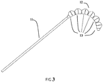
- Figure 3 is a schematic diagram of the balloon retractor or pulling device of the present invention filled with fluid.
- each expansion section 13 of the balloon 12 is filled with fluid to expand and squeeze or press against each other to form a curved profile.
- the axis of the balloon 12 does not coincide with the axis of the core tube 11, the axis of each expansion section 13 is located on one side of the core tube 11, so that each expansion section 13 will accumulate the degree of bending after being filled with fluid, that is, expansion.
- each balloon 12 may be individually control the bending of a part of the core tube 11 shape.
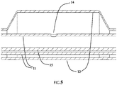
- FIG. 4 is a cross-sectional view of the balloon retractor or pulling device of the present invention
- FIG. 5 is a partial enlarged view of the cross-sectional view of the balloon retractor of the present invention.
- the core tube 11 has holes 14 on the surface covered by the balloon 12 or has corresponding holes 14 for each expansion section 13.
- the core tube 11 can be a plurality of independent core tubes 11, each core tube 11 individually controls the inflation and discharging of the inflation section 13 of a single balloon 12; it can also be a multi-lumen tube, each of which individually controls a single balloon 12 charge and discharge, or expansion and contraction, of the expansion section 13.
- the inflation or expansion sections 13 of the balloon 12 may be connected to or in communication with each other through a non-inflatable section, or may be various independent and disconnected inflated sections, for example, composed of multiple independent small inflatable balloons or each section of the non-inflated section is tightly tied. Both ends of the balloon may be connected with a wire-like material 15 with low ductility.
- the filamentous material 15 may be disposed in the lumen of the core tube 11 as shown in FIG. 5 , or may be disposed on the outer surface of the core tube.
- the filamentary material 15 is made of a metal material with a relatively large modulus, such as metal, to ensure that the corresponding part of the core tube will not be elongated when the balloon 12 is inflated, thereby reducing the degree of bending and causing deformation of the core tube.
- the length of the inflation or expanded section 13 of the balloon 12 is greater than the outer diameter of the uninflated or unexpanded state.
- the adjacent interval between the expansion sections 13 of the balloon 12 is less than 0.2 times the length of the expansion section 13.
- the balloon retractor or pulling device is extended into the patient's lumen (minimally invasive lumen or natural lumen), and part of the fluid is first filled (preferably, the internal pressure is between 1-4 atmospheric pressure), and the distal balloon 12 will be visibly bent.
- the imaging device is used for positioning, and the handle is rotated and pushed to make the angle and position of the device reach the desired state. Then continue filling the device with liquid (preferably, the internal pressure of the device reaches between 4-6 atmospheres), and the balloon 12 will remain bent to the maximum extent, thereby achieving the purpose of pulling away the target tissue.
- the present invention also provides a method for manufacturing a balloon retractor or pulling device including the following steps:
- thermoplastic polymer material is selected, melted and extruded into a barrel or material tube. Milling the balloon forming mold, the mold is divided into two halves, and the shape of the inner cavity after the two mold halves are spliced is consistent with the final outer contour of the balloon 12. The spliced mold is placed on the balloon forming machine, and the material tube is placed in the cavity. Set the molding temperature, molding internal pressure and stretching rate, stretch and expand the material tube so that the outer wall of the final material tube is adhered or applied to the inner wall of the mold cavity.
- the material tube After the material tube is completely adhered or applied to the inner wall of the mold cavity, maintain the molding pressure and start at the same time external water cooling. External water is cooled until it is consistent with the ambient temperature. Then the mold is demolded or released, the mold is removed, the two molds halves are separated again, and the formed balloon 12 is taken out. At this time, the balloon 12 has an expansion section 13 part and a non-expansion section part according to the shape of the mold. It is also possible to disregard the expansion and non-expansion parts, and restrict the non-expansion part after the balloon 12 is set to the preset position so that it cannot be expanded significantly.
- the core tube 11 is extruded, a thermoplastic polymer material is selected, and then extruded after melting to form a single-lumen or multi-lumen tube.
- a small hole 14 is punched in the core tube 11 using a catheter puncher.
- the balloon 12 is placed in a preset position, and the balloon 12 is fixed or secured on or over the core tube 11 by welding or glue bonding.
- the filamentary material 15 should be a metal wire with less ductility (large modulus), one end fixed near the distal end of the core tube 11 (preferably the distal end of the balloon 12). The other end is fixed near the proximal end of the core tube 11 (preferably the proximal end of the balloon 12), and glue is used to bond the filamentous material 15 and the core tube 11 together.
- the preparation method in the case of multiple balloons firstly, select a thermoplastic polymer material, melt it and extrude it into a barrel or material tube. Milling the balloon forming mold, the mold is divided into two halves, and the shape of the internal cavity after the two mold halves are spliced is consistent with the final outer contour of the single balloon 12.
- the spliced mold is placed on a balloon forming machine, and the material tube is placed in the cavity. Set the molding temperature, molding internal pressure and stretching rate, stretch and expand the material tube so that the outer wall of the final material tube is adhered or applied to the inner wall of the mold cavity. After the material tube is completely adhered or applied to the inner wall of the entire mold cavity, maintain the molding pressure and start at the same time external water cooling.
- the balloon 12 has an expansion section 13 part and a non-expansion section part according to the shape of the mold. It is also possible to disregard the expansion and non-expansion parts, and restrict the non-expansion part after the balloon 12 is set to the preset position so that it cannot be expanded significantly.
- the core tube 11 is extruded, and a thermoplastic polymer material is selected, melted, and extruded to form a multi-lumen tube having a number of cavities greater than or equal to the number of balloons 12 needed.
- a catheter puncher is used to punch holes 14 in the multi-lumen tube.
- the number of holes 14 is the same as the number of balloons used.
- the axial distance between two adjacent holes 14 should be slightly greater than the length of the balloon 12, preferably, the distance is the sum of the length of the balloon 12 and the predetermined gap between the balloons 12.
- a plurality of balloons 12 are placed in preset positions, and the balloons 12 are fixed on the core tube 11 by welding or adhesive bonding, respectively.
- the manufacturing method also includes after fixing the balloon to the core tube, fixing one end of the filamentous material 15 near the distal end of the core tube 11, and fixing the other end near the proximal end of the core tube 11, and then attaching the filamentous material 15 to the core tube.
- the tube 11 is glued.
Landscapes
- Health & Medical Sciences (AREA)
- Life Sciences & Earth Sciences (AREA)
- Engineering & Computer Science (AREA)
- Surgery (AREA)
- Heart & Thoracic Surgery (AREA)
- Veterinary Medicine (AREA)
- Public Health (AREA)
- General Health & Medical Sciences (AREA)
- Biomedical Technology (AREA)
- Animal Behavior & Ethology (AREA)
- Molecular Biology (AREA)
- Medical Informatics (AREA)
- Nuclear Medicine, Radiotherapy & Molecular Imaging (AREA)
- Mechanical Engineering (AREA)
- Manufacturing & Machinery (AREA)
- Anesthesiology (AREA)
- Hematology (AREA)
- Vascular Medicine (AREA)
- Child & Adolescent Psychology (AREA)
- Biophysics (AREA)
- Pulmonology (AREA)
- Media Introduction/Drainage Providing Device (AREA)
- Surgical Instruments (AREA)
Applications Claiming Priority (2)
| Application Number | Priority Date | Filing Date | Title |
|---|---|---|---|
| CN201810165074.9A CN110192901A (zh) | 2018-02-27 | 2018-02-27 | 球囊牵拉装置及其制造方法 |
| PCT/CN2018/103279 WO2019165772A1 (fr) | 2018-02-27 | 2018-08-30 | Dispositif de traction de ballonnet et son procédé de fabrication |
Publications (2)
| Publication Number | Publication Date |
|---|---|
| EP3760131A1 true EP3760131A1 (fr) | 2021-01-06 |
| EP3760131A4 EP3760131A4 (fr) | 2021-09-29 |
Family
ID=67750982
Family Applications (1)
| Application Number | Title | Priority Date | Filing Date |
|---|---|---|---|
| EP18907619.3A Pending EP3760131A4 (fr) | 2018-02-27 | 2018-08-30 | Dispositif de traction de ballonnet et son procédé de fabrication |
Country Status (5)
| Country | Link |
|---|---|
| US (1) | US11678871B2 (fr) |
| EP (1) | EP3760131A4 (fr) |
| JP (1) | JP7108698B2 (fr) |
| CN (1) | CN110192901A (fr) |
| WO (1) | WO2019165772A1 (fr) |
Cited By (2)
| Publication number | Priority date | Publication date | Assignee | Title |
|---|---|---|---|---|
| JP2024507217A (ja) * | 2021-02-19 | 2024-02-16 | 上海科▲賜▼医▲療▼技▲術▼有限公司 | バルーンカテーテルリトラクタ |
| EP4356846A4 (fr) * | 2021-06-18 | 2025-06-18 | Shanghai Keci Medical Technology Co., Ltd | Dispositif à ballonnet de flexion anti-torsion |
Families Citing this family (11)
| Publication number | Priority date | Publication date | Assignee | Title |
|---|---|---|---|---|
| CN111419304A (zh) * | 2020-04-16 | 2020-07-17 | 上海科赐医疗技术有限公司 | 弯曲球囊导管牵开器 |
| CN112546404A (zh) * | 2021-01-19 | 2021-03-26 | 山东第一医科大学附属省立医院(山东省立医院) | 带有意外拔出防损伤型导尿管 |
| CN113456143A (zh) * | 2021-08-10 | 2021-10-01 | 西安交通大学医学院第一附属医院 | 一种用于消化道重建的双球囊吻合器 |
| CN113796821B (zh) * | 2021-09-24 | 2024-05-07 | 南方科技大学 | 一种具有自主弯曲功能的肠镜系统及其自主弯曲方法 |
| CN113941074B (zh) * | 2021-11-12 | 2024-05-24 | 北京大学深圳医院 | 高龄病人胃镜检查用咽部扩张装置 |
| JP2025517345A (ja) * | 2022-05-17 | 2025-06-05 | ボストン サイエンティフィック サイムド,インコーポレイテッド | 組織牽引のためのデバイス、システム、及び方法 |
| CN115700126A (zh) * | 2022-11-10 | 2023-02-07 | 复旦大学附属中山医院 | 一种可定向弯曲的介入导管组件 |
| CN115887878B (zh) * | 2023-01-06 | 2026-04-21 | 上海佳沐垚医疗科技有限公司 | 球囊导管装置 |
| CN116328160A (zh) * | 2023-04-11 | 2023-06-27 | 中国人民解放军西部战区总医院 | 一种ercp辅助胆管超选装置 |
| CN118648851B (zh) * | 2024-08-19 | 2025-02-07 | 湖南省华芯医疗器械有限公司 | 一种主动弯曲段、插入部及内窥镜 |
| CN119244858B (zh) * | 2024-12-05 | 2025-03-25 | 四川中科高新技术集团有限公司 | 排水管道非开挖修复气囊 |
Family Cites Families (36)
| Publication number | Priority date | Publication date | Assignee | Title |
|---|---|---|---|---|
| US4862886A (en) | 1985-05-08 | 1989-09-05 | Summit Technology Inc. | Laser angioplasty |
| US4763654A (en) | 1986-09-10 | 1988-08-16 | Jang G David | Tandem independently inflatable/deflatable multiple diameter balloon angioplasty catheter systems and method of use |
| USD303288S (en) | 1986-09-12 | 1989-09-05 | Ballobes Aps | Intragastric balloon kit consisting of an intragastric balloon device, a pump, a container tube and a box |
| US5147377A (en) | 1988-11-23 | 1992-09-15 | Harvinder Sahota | Balloon catheters |
| CN2120592U (zh) | 1992-03-21 | 1992-11-04 | 仇德惠 | 食管手术导管 |
| USD360260S (en) | 1993-02-09 | 1995-07-11 | Montefiore Hospital And Medical Center | Esophageal cytology balloon catheter |
| USD390659S (en) | 1997-03-31 | 1998-02-10 | Bristol-Myers Squibb Company | Bone cement scoop |
| US20030045923A1 (en) | 2001-08-31 | 2003-03-06 | Mehran Bashiri | Hybrid balloon expandable/self expanding stent |
| US20030229332A1 (en) * | 2002-06-11 | 2003-12-11 | Scimed Life Systems, Inc. | Adjustable double balloon catheter with a through lumen for stone management |
| US7309324B2 (en) | 2004-10-15 | 2007-12-18 | Futuremed Interventional, Inc. | Non-compliant medical balloon having an integral woven fabric layer |
| US9586022B2 (en) * | 2006-01-25 | 2017-03-07 | Mayser, Llc | Stretch valve balloon catheter and methods for producing and using same |
| EP1892007B1 (fr) * | 2005-06-14 | 2011-10-26 | Vayu Co., Ltd | Cathéter à ballonnet |
| WO2007020087A1 (fr) | 2005-08-19 | 2007-02-22 | Abbott Laboratories Vascular Enterprises Limited | Procédé de fabrication d’un ballonnet d’un cathéter à ballonnet |
| CN201333252Y (zh) | 2008-12-25 | 2009-10-28 | 毛瑞敏 | 宫颈扩张器 |
| US9186181B2 (en) * | 2009-03-17 | 2015-11-17 | Pivot Medical, Inc. | Method and apparatus for distracting a joint |
| US9937329B2 (en) * | 2009-10-06 | 2018-04-10 | Niazi Licensing Corporation | Intra-esophageal balloon system |
| US20120071823A1 (en) | 2010-09-22 | 2012-03-22 | Boston Scientific Scimed, Inc. | Medical balloon having improved stability and strength |
| BR112013011761A2 (pt) | 2010-11-12 | 2017-06-27 | Smith & Nephew Inc | balão inflável e direcionável para elevação de tecido dentro de um corpo |
| US20140012304A1 (en) | 2012-07-03 | 2014-01-09 | Merit Medical Systems, Inc. | Multilayered balloon |
| EP2934344A2 (fr) | 2012-12-21 | 2015-10-28 | University College Cork, National University Of Ireland | Rétracteur laparoscopique gonflable pour rétraction atraumatique au cours d'une chirurgie abdominale |
| CN103055411B (zh) | 2013-01-25 | 2014-03-12 | 业聚医疗器械(深圳)有限公司 | 球囊导管及其制作方法 |
| US9839543B2 (en) * | 2013-03-14 | 2017-12-12 | Cook Medical Technologies Llc | Multi-stage balloon catheter |
| CA2901443A1 (fr) | 2013-03-15 | 2014-09-25 | Insera Therapeutics, Inc. | Dispositifs et procedes de traitement vasculaire |
| EP2805695A1 (fr) * | 2013-05-21 | 2014-11-26 | Medtentia International Ltd Oy | Système médical pour annuloplastie |
| CN104189989A (zh) * | 2014-09-19 | 2014-12-10 | 广州启骏生物科技有限公司 | 止血球囊导管及其制备方法 |
| US10028734B2 (en) | 2014-11-13 | 2018-07-24 | Soft Robotics, Inc. | Soft robotic retractors |
| WO2016141195A1 (fr) * | 2015-03-04 | 2016-09-09 | Transmed7, Llc | Cathéter à ballonnet d'élution de médicament, adaptable, orientable |
| JP6976512B2 (ja) * | 2015-03-27 | 2021-12-08 | プロジェクト モレー, インコーポレイテッド | カテーテルおよびその他の使用のための関節運動システム、デバイス、および方法 |
| CN204581372U (zh) | 2015-04-24 | 2015-08-26 | 中国人民解放军总医院 | 一种腔镜用直肠固定牵拉装置 |
| CN104921853A (zh) | 2015-06-25 | 2015-09-23 | 四川大学华西医院 | 一种食管支撑装置 |
| CN105997161A (zh) * | 2016-04-27 | 2016-10-12 | 凌安东 | 一种腹腔镜手术用的水囊肠垫 |
| US20180008444A1 (en) * | 2016-07-11 | 2018-01-11 | Cook Medical Technologies Llc | Multi-stage balloon catheter, and method of operating same in a curved passageway |
| CN106422038A (zh) * | 2016-09-28 | 2017-02-22 | 上海凯利泰医疗科技股份有限公司 | 一种椎体扩张球囊导管 |
| USD851245S1 (en) | 2017-04-14 | 2019-06-11 | Cardiofocus, Inc. | Compliant balloon |
| CN107261301A (zh) * | 2017-05-04 | 2017-10-20 | 杭州启明医疗器械有限公司 | 一种球囊导管及其制备方法和医疗装置 |
| USD879958S1 (en) | 2018-07-18 | 2020-03-31 | Shanghaí Kecì Medical Technology Co., Ltd. | Medical balloon Group |
-
2018
- 2018-02-27 CN CN201810165074.9A patent/CN110192901A/zh active Pending
- 2018-08-30 JP JP2020545625A patent/JP7108698B2/ja active Active
- 2018-08-30 WO PCT/CN2018/103279 patent/WO2019165772A1/fr not_active Ceased
- 2018-08-30 EP EP18907619.3A patent/EP3760131A4/fr active Pending
- 2018-08-30 US US16/976,407 patent/US11678871B2/en active Active
Cited By (2)
| Publication number | Priority date | Publication date | Assignee | Title |
|---|---|---|---|---|
| JP2024507217A (ja) * | 2021-02-19 | 2024-02-16 | 上海科▲賜▼医▲療▼技▲術▼有限公司 | バルーンカテーテルリトラクタ |
| EP4356846A4 (fr) * | 2021-06-18 | 2025-06-18 | Shanghai Keci Medical Technology Co., Ltd | Dispositif à ballonnet de flexion anti-torsion |
Also Published As
| Publication number | Publication date |
|---|---|
| US11678871B2 (en) | 2023-06-20 |
| US20210113202A1 (en) | 2021-04-22 |
| CN110192901A (zh) | 2019-09-03 |
| JP7108698B2 (ja) | 2022-07-28 |
| WO2019165772A1 (fr) | 2019-09-06 |
| JP2021514763A (ja) | 2021-06-17 |
| EP3760131A4 (fr) | 2021-09-29 |
Similar Documents
| Publication | Publication Date | Title |
|---|---|---|
| US11678871B2 (en) | Balloon pulling device and manufacturing method therefor | |
| EP3641676B1 (fr) | Dispositif d'introduction pour ensemble de tamponnement utérin | |
| US5833657A (en) | Single-walled balloon catheter with non-linear compliance characteristic | |
| CA1329091C (fr) | Catheter dote d'un dispositif de retenue du ballonnet | |
| JP3339003B2 (ja) | 薬物を供給するための膨張可能な医療用装置及びその製造方法 | |
| US8961532B2 (en) | Atraumatic catheter tip | |
| JP2918502B2 (ja) | ステント挿入用バルーンカテーテル | |
| US10617849B2 (en) | Balloon with variable pitch reinforcing fibers | |
| US11331456B2 (en) | Multilayer balloons | |
| EP0745395B1 (fr) | Ballonnet avec membrane réglable à base de peek | |
| JPH09503678A (ja) | バルーンカテーテル用鞘 | |
| HK1007518B (en) | An angioplasty catheter and a method of making the same | |
| JPH11514891A (ja) | 低断面形状バルーンカテーテル及び方法 | |
| WO2001054568A1 (fr) | Dispositif et procede d'elargissement d'une cavite | |
| JP2008538518A (ja) | 組織拡張装置および関連方法 | |
| US20060271092A1 (en) | Balloon-in-balloon cervical canal dilator | |
| EP3329959B1 (fr) | Instrument de traitement pour endoscope | |
| US9402983B1 (en) | Variably expanding balloon catheter | |
| EP1507571B1 (fr) | Dilatateur servant a elargir un passage vers un corps | |
| CN107693063A (zh) | 手术创口牵开装置 | |
| WO2023081072A1 (fr) | Dispositif de tamponnement utérin | |
| CN111369858A (zh) | 一种模拟牵开脑组织的方法 | |
| CN219127925U (zh) | 一种用于tips手术的导管、套件 | |
| CN211023325U (zh) | 一种手术钳 | |
| CN114681765A (zh) | 扩张球囊及球囊扩张导管 |
Legal Events
| Date | Code | Title | Description |
|---|---|---|---|
| STAA | Information on the status of an ep patent application or granted ep patent |
Free format text: STATUS: THE INTERNATIONAL PUBLICATION HAS BEEN MADE |
|
| PUAI | Public reference made under article 153(3) epc to a published international application that has entered the european phase |
Free format text: ORIGINAL CODE: 0009012 |
|
| STAA | Information on the status of an ep patent application or granted ep patent |
Free format text: STATUS: REQUEST FOR EXAMINATION WAS MADE |
|
| 17P | Request for examination filed |
Effective date: 20200923 |
|
| AK | Designated contracting states |
Kind code of ref document: A1 Designated state(s): AL AT BE BG CH CY CZ DE DK EE ES FI FR GB GR HR HU IE IS IT LI LT LU LV MC MK MT NL NO PL PT RO RS SE SI SK SM TR |
|
| AX | Request for extension of the european patent |
Extension state: BA ME |
|
| DAV | Request for validation of the european patent (deleted) | ||
| DAX | Request for extension of the european patent (deleted) | ||
| A4 | Supplementary search report drawn up and despatched |
Effective date: 20210827 |
|
| RIC1 | Information provided on ipc code assigned before grant |
Ipc: A61B 17/22 20060101ALI20210823BHEP Ipc: A61B 17/00 20060101ALI20210823BHEP Ipc: A61B 17/02 20060101AFI20210823BHEP |
|
| STAA | Information on the status of an ep patent application or granted ep patent |
Free format text: STATUS: EXAMINATION IS IN PROGRESS |
|
| 17Q | First examination report despatched |
Effective date: 20230727 |