EP3760255B1 - Seringue, ensemble de seringue et procédé de fabrication de seringue - Google Patents
Seringue, ensemble de seringue et procédé de fabrication de seringue Download PDFInfo
- Publication number
- EP3760255B1 EP3760255B1 EP19775174.6A EP19775174A EP3760255B1 EP 3760255 B1 EP3760255 B1 EP 3760255B1 EP 19775174 A EP19775174 A EP 19775174A EP 3760255 B1 EP3760255 B1 EP 3760255B1
- Authority
- EP
- European Patent Office
- Prior art keywords
- distal end
- wall surface
- syringe
- body portion
- concave
- Prior art date
- Legal status (The legal status is an assumption and is not a legal conclusion. Google has not performed a legal analysis and makes no representation as to the accuracy of the status listed.)
- Active
Links
Images




Classifications
-
- A—HUMAN NECESSITIES
- A61—MEDICAL OR VETERINARY SCIENCE; HYGIENE
- A61M—DEVICES FOR INTRODUCING MEDIA INTO, OR ONTO, THE BODY; DEVICES FOR TRANSDUCING BODY MEDIA OR FOR TAKING MEDIA FROM THE BODY; DEVICES FOR PRODUCING OR ENDING SLEEP OR STUPOR
- A61M5/00—Devices for bringing media into the body in a subcutaneous, intra-vascular or intramuscular way; Accessories therefor, e.g. filling or cleaning devices, arm-rests
- A61M5/178—Syringes
- A61M5/31—Details
- A61M5/3129—Syringe barrels
-
- A—HUMAN NECESSITIES
- A61—MEDICAL OR VETERINARY SCIENCE; HYGIENE
- A61M—DEVICES FOR INTRODUCING MEDIA INTO, OR ONTO, THE BODY; DEVICES FOR TRANSDUCING BODY MEDIA OR FOR TAKING MEDIA FROM THE BODY; DEVICES FOR PRODUCING OR ENDING SLEEP OR STUPOR
- A61M5/00—Devices for bringing media into the body in a subcutaneous, intra-vascular or intramuscular way; Accessories therefor, e.g. filling or cleaning devices, arm-rests
- A61M5/178—Syringes
- A61M5/31—Details
- A61M5/3129—Syringe barrels
- A61M5/3134—Syringe barrels characterised by constructional features of the distal end, i.e. end closest to the tip of the needle cannula
-
- A—HUMAN NECESSITIES
- A61—MEDICAL OR VETERINARY SCIENCE; HYGIENE
- A61J—CONTAINERS SPECIALLY ADAPTED FOR MEDICAL OR PHARMACEUTICAL PURPOSES; DEVICES OR METHODS SPECIALLY ADAPTED FOR BRINGING PHARMACEUTICAL PRODUCTS INTO PARTICULAR PHYSICAL OR ADMINISTERING FORMS; DEVICES FOR ADMINISTERING FOOD OR MEDICINES ORALLY; BABY COMFORTERS; DEVICES FOR RECEIVING SPITTLE
- A61J1/00—Containers specially adapted for medical or pharmaceutical purposes
- A61J1/14—Details; Accessories therefor
- A61J1/20—Arrangements for transferring or mixing fluids, e.g. from vial to syringe
- A61J1/2003—Accessories used in combination with means for transfer or mixing of fluids, e.g. for activating fluid flow, separating fluids, filtering fluid or venting
- A61J1/2048—Connecting means
- A61J1/2055—Connecting means having gripping means
-
- A—HUMAN NECESSITIES
- A61—MEDICAL OR VETERINARY SCIENCE; HYGIENE
- A61J—CONTAINERS SPECIALLY ADAPTED FOR MEDICAL OR PHARMACEUTICAL PURPOSES; DEVICES OR METHODS SPECIALLY ADAPTED FOR BRINGING PHARMACEUTICAL PRODUCTS INTO PARTICULAR PHYSICAL OR ADMINISTERING FORMS; DEVICES FOR ADMINISTERING FOOD OR MEDICINES ORALLY; BABY COMFORTERS; DEVICES FOR RECEIVING SPITTLE
- A61J1/00—Containers specially adapted for medical or pharmaceutical purposes
- A61J1/14—Details; Accessories therefor
- A61J1/20—Arrangements for transferring or mixing fluids, e.g. from vial to syringe
- A61J1/2096—Combination of a vial and a syringe for transferring or mixing their contents
-
- A—HUMAN NECESSITIES
- A61—MEDICAL OR VETERINARY SCIENCE; HYGIENE
- A61M—DEVICES FOR INTRODUCING MEDIA INTO, OR ONTO, THE BODY; DEVICES FOR TRANSDUCING BODY MEDIA OR FOR TAKING MEDIA FROM THE BODY; DEVICES FOR PRODUCING OR ENDING SLEEP OR STUPOR
- A61M5/00—Devices for bringing media into the body in a subcutaneous, intra-vascular or intramuscular way; Accessories therefor, e.g. filling or cleaning devices, arm-rests
- A61M5/178—Syringes
- A61M5/31—Details
- A61M5/3129—Syringe barrels
- A61M2005/3131—Syringe barrels specially adapted for improving sealing or sliding
-
- A—HUMAN NECESSITIES
- A61—MEDICAL OR VETERINARY SCIENCE; HYGIENE
- A61M—DEVICES FOR INTRODUCING MEDIA INTO, OR ONTO, THE BODY; DEVICES FOR TRANSDUCING BODY MEDIA OR FOR TAKING MEDIA FROM THE BODY; DEVICES FOR PRODUCING OR ENDING SLEEP OR STUPOR
- A61M5/00—Devices for bringing media into the body in a subcutaneous, intra-vascular or intramuscular way; Accessories therefor, e.g. filling or cleaning devices, arm-rests
- A61M5/178—Syringes
- A61M5/31—Details
- A61M5/315—Pistons; Piston-rods; Guiding, blocking or restricting the movement of the rod or piston; Appliances on the rod for facilitating dosing ; Dosing mechanisms
- A61M5/31511—Piston or piston-rod constructions, e.g. connection of piston with piston-rod
- A61M2005/31516—Piston or piston-rod constructions, e.g. connection of piston with piston-rod reducing dead-space in the syringe barrel after delivery
-
- A—HUMAN NECESSITIES
- A61—MEDICAL OR VETERINARY SCIENCE; HYGIENE
- A61M—DEVICES FOR INTRODUCING MEDIA INTO, OR ONTO, THE BODY; DEVICES FOR TRANSDUCING BODY MEDIA OR FOR TAKING MEDIA FROM THE BODY; DEVICES FOR PRODUCING OR ENDING SLEEP OR STUPOR
- A61M2207/00—Methods of manufacture, assembly or production
-
- A—HUMAN NECESSITIES
- A61—MEDICAL OR VETERINARY SCIENCE; HYGIENE
- A61M—DEVICES FOR INTRODUCING MEDIA INTO, OR ONTO, THE BODY; DEVICES FOR TRANSDUCING BODY MEDIA OR FOR TAKING MEDIA FROM THE BODY; DEVICES FOR PRODUCING OR ENDING SLEEP OR STUPOR
- A61M5/00—Devices for bringing media into the body in a subcutaneous, intra-vascular or intramuscular way; Accessories therefor, e.g. filling or cleaning devices, arm-rests
- A61M5/178—Syringes
- A61M5/28—Syringe ampoules or carpules, i.e. ampoules or carpules provided with a needle
- A61M5/281—Syringe ampoules or carpules, i.e. ampoules or carpules provided with a needle using emptying means to expel or eject media, e.g. pistons, deformation of the ampoule, or telescoping of the ampoule
-
- A—HUMAN NECESSITIES
- A61—MEDICAL OR VETERINARY SCIENCE; HYGIENE
- A61M—DEVICES FOR INTRODUCING MEDIA INTO, OR ONTO, THE BODY; DEVICES FOR TRANSDUCING BODY MEDIA OR FOR TAKING MEDIA FROM THE BODY; DEVICES FOR PRODUCING OR ENDING SLEEP OR STUPOR
- A61M5/00—Devices for bringing media into the body in a subcutaneous, intra-vascular or intramuscular way; Accessories therefor, e.g. filling or cleaning devices, arm-rests
- A61M5/178—Syringes
- A61M5/31—Details
- A61M5/32—Needles; Details of needles pertaining to their connection with syringe or hub; Accessories for bringing the needle into, or holding the needle on, the body; Devices for protection of needles
- A61M5/3202—Devices for protection of the needle before use, e.g. caps
Definitions
- the present invention relates to a syringe, a syringe assembly, and a manufacturing method of a syringe.
- JP 2013-132349 A discloses a syringe provided with a body portion including an inner cavity capable of being filled with a medicinal solution, a female port nozzle portion which extends from a distal end of the body portion into which a male port nozzle portion being a male luer is inserted, and a proximal end opening formed on a proximal end portion of the body portion.
- the syringe in a process of manufacturing, storing, and transporting the syringe assembly, the syringe might be held for a long time in a state in which the syringe is set up such that a distal end of the female port nozzle portion faces downward. Then, the liquid lubricant applied to the inner peripheral surface of the syringe (gasket sliding surface of the syringe) might drip due to gravity and adhere to the inner peripheral surface of the female port nozzle portion.
- connection strength of connection between the female port nozzle portion (female luer) and the male port nozzle portion (male luer) decreases, causing looseness to reduce liquid tightness or transfer of the liquid lubricant to the male port nozzle portion, so that there is a possibility that the male port nozzle portion and another device (for example, an injection needle) cannot be connected properly.
- the present invention is achieved in view of such a problem, and an object thereof is to provide a syringe, a syringe assembly, and a manufacturing method of a syringe capable of suppressing the liquid lubricant from adhering to the inner peripheral surface of the female port nozzle portion and securing prevention of the connection strength of the luer taper connection from lowering and prevention of the liquid lubricant from transferring to the male port nozzle portion.
- a syringe is a syringe provided with a body portion including an inner cavity capable of being filled with a medicinal solution, a female port nozzle portion that extends from a distal end of the body portion into which a male luer is inserted, and a proximal end opening formed on a proximal end portion of the body portion, in which the female port nozzle portion includes a communication port through which an inner portion of the female port nozzle portion is communicated with the inner cavity of the body portion on a proximal end of the female port nozzle portion, the body portion includes a distal end wall surface that extends radially outward from the communication port of the female port nozzle portion and faces the inner cavity, and a side wall surface that extends from an outer edge of the distal end wall surface in a proximal end direction and faces the inner cavity, the distal end wall surface of the body portion includes an inner edge portion adjacent to the communication port of the female port
- the liquid lubricant dripping from the inner peripheral surface to the distal end wall surface of the body portion may be stored in the concave portion, so that it is possible to suppress the liquid lubricant from adhering to the inner peripheral surface of the female port nozzle portion.
- the concave portion may include a first concave portion adjacent to the inner edge portion, and a second concave portion arranged radially outside the first concave portion.
- the liquid lubricant may be stored in the first concave portion and the second concave portion, so that it is possible to further suppress the liquid lubricant from adhering to the inner peripheral surface of the female port nozzle portion.
- the distal end wall surface may include an inclined surface inclined in the proximal end direction from the vicinity of the outer edge of the distal end wall surface to the vicinity of the communication port of the female port nozzle portion, and the concave portion may be formed of an outer edge portion of the inclined surface.
- each of the first concave portion and the second concave portion may extend in a range smaller than 360° in a circumferential direction of the body portion, and the second concave portion may be arranged so as to cover an entire flat surface portion adjacent to the inner edge portion in which the first concave portion is not formed out of the distal end wall surface from radially outside.
- each of a plurality of first concave portions and a plurality of second concave portions may be arranged at intervals in the circumferential direction of the body portion, and the second concave portions may be arranged so as to cover the flat surface portion located between the first concave portions adjacent to each other from radially outside.
- liquid lubricant is not substantially applied on an inner peripheral surface of the female port nozzle portion.
- connection strength of the luer taper connection it is possible to further secure prevention of the connection strength of the luer taper connection from lowering and prevention of the liquid lubricant from transferring to the male port nozzle portion.
- a syringe assembly according to the present invention is provided with the syringe described above, and a gasket arranged in the body portion of the syringe and slidable on the side wall surface of the body portion, in which the distal end wall surface of the body portion includes an outer edge portion between the concave portion and the outer edge, and the gasket includes a distal end face capable of abutting the outer edge portion of the distal end wall surface.
- the distal end face of the gasket may include a convex portion insertable into the concave portion of the distal end wall surface of the body portion.
- a portion facing the distal end wall surface out of the distal end face of the gasket may have a shape substantially the same as a shape of the distal end wall surface of the body portion.
- the distal end face of the gasket may be configured to abut the outer edge portion of the distal end wall surface of the body portion before abutting the inner edge portion of the distal end wall surface of the body portion when the gasket is displaced in the distal end direction with respect to the body portion.
- a manufacturing method of a syringe according to the present invention is a manufacturing method of a syringe provided with a body portion including an inner cavity capable of being filled with a medicinal solution, a female port nozzle portion that extends from a distal end of the body portion into which a male luer is inserted, and a proximal end opening formed on a proximal end portion of the body portion, the method provided with preparing the syringe in which the female port nozzle portion includes a communication port through which an inner portion of the female port nozzle portion is communicated with the inner cavity of the body portion on a proximal end of the female port nozzle portion, the body portion includes a distal end wall surface that extends radially outward from the communication port of the female port nozzle portion and faces the inner cavity, and a side wall surface that extends from an outer edge of the distal end wall surface in a proximal end direction and faces the inner cavity, and the distal end wall surface of the body portion includes an inner
- the liquid lubricant is stored in the concave portion of the distal end wall surface, so that the liquid lubricant is not substantially applied on an inner peripheral surface of the female port nozzle portion.
- connection strength of the luer taper connection it is possible to further secure prevention of the connection strength of the luer taper connection from lowering and prevention of the liquid lubricant from transferring to the male port nozzle portion.
- the syringe is held in the storage container in a state in which the distal end of the female port nozzle portion faces downward, so that storage, conveyance and the like of the syringe may be efficiently performed. Furthermore, at that time, the liquid lubricant dripping from the side wall surface to the distal end wall surface of the body portion may be stored in the concave portion, so that it is possible to suppress the liquid lubricant from adhering to the inner peripheral surface of the female port nozzle portion.
- the liquid lubricant dripping from the side wall surface to the distal end wall surface of the body portion may be stored in the concave portion of the distal end wall surface, so that it is possible to suppress the liquid lubricant from adhering to the inner peripheral surface of the female port nozzle portion.
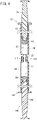
- a syringe assembly 10 is provided with a syringe 12, a cap 14 attached to a distal end portion of the syringe 12, a gasket 16 inserted into the syringe 12 so as to be slidable therein in a liquid-tight manner, and a pusher 18 connected to the gasket 16.
- the syringe assembly 10 is configured as a prefilled syringe filled with a medicinal solution M1 in advance.
- the syringe 12 is provided with a body portion 20 including an inner cavity 19 capable of being filled with the medicinal solution M1, a female port nozzle portion 22 which extends from a distal end of the body portion 20 into which a male port nozzle portion 110 (refer to Fig. 5 ) being a male luer is inserted, a proximal end opening 24 formed on a proximal end portion of the body portion 20, and a distal end opening 25 formed on a distal end portion of the female port nozzle portion 22.
- the body portion 20 is a hollow cylindrical portion into which the gasket 16 is slidably inserted.
- a flange 26 projecting radially outward is formed on an outer peripheral portion of the proximal end of the body portion 20.
- the body portion 20 includes a side wall surface 28 and a distal end wall surface 30.
- the side wall surface 28 of the body portion 20 extends from an outer edge of the distal end wall surface 30 in a proximal end direction and faces the inner cavity 19 of the body portion 20.
- liquid lubricant L is applied substantially uniformly in order to improve slidability of the gasket 16.
- the liquid lubricant L for example, silicone oil is used.
- the liquid lubricant L is not limited to the silicone oil, and various types may also be used.
- the distal end wall surface 30 of the body portion 20 extends from a communication port 32 provided on a proximal end of the female port nozzle portion 22 radially outward and faces the inner cavity 19 of the body portion 20.
- the distal end wall surface 30 includes an inner edge portion 34 adjacent to the communication port 32 of the female port nozzle portion 22, a concave portion 36a arranged radially outside the inner edge portion 34 and is concave in a distal end direction from at least a part of the inner edge portion 34 (for example, a site located in a radially outermost portion of the inner edge portion 34), and an outer edge portion 38 between the concave portion 36a and the outer edge.
- the distal end wall surface 30 is inclined from the outer edge to the inner edge portion 34 in the distal end direction.
- the concave portion 36a is arranged so as to fully surround the communication port 32 of the female port nozzle portion 22 and is able to store the liquid lubricant L.
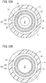
- the concave portion 36a is an annular groove extending 360° in a circumferential direction of the body portion 20 (refer to Fig. 3A ).
- the concave portion 36a includes an inner surface a cross-section of which is circular (refer to Fig. 2 ).
- an interval between the communication port 32 and the concave portion 36a is shorter than an interval between the outer edge of the distal end wall surface 30 and the concave portion 36a.
- a position in which the concave portion 36a is provided with respect to the distal end wall surface 30 may be set arbitrarily.
- a size (depth dimension and width dimension) of the concave portion 36a is determined according to an amount of the liquid lubricant L applied to the side wall surface 28 of the body portion 20.
- the size of the concave portion 36a is set such that a larger amount of liquid lubricant L than the amount of the liquid lubricant L applied to the side wall surface 28 of the body portion 20 may be stored (for example, 10 times the applied amount or more).
- the size of the concave portion 36a may be set arbitrarily.
- the female port nozzle portion 22 includes the communication port 32 with which an inner portion 23 of the female port nozzle portion 22 and the inner cavity 19 of the body portion 20 are communicated with each other on the proximal end of the female port nozzle portion 22.
- the female port nozzle portion 22 includes an inner peripheral surface 40 which may come into contact with an outer peripheral surface 116 (refer to Fig. 5 ) of the male port nozzle portion 110.
- the inner peripheral surface 40 is formed such that an inner diameter increases in the distal end direction.
- the liquid lubricant L is not substantially applied to the inner peripheral surface 40 of the female port nozzle portion 22.
- a fixing unit 42 which attachably/detachably fixes the cap 14 is provided on an outer peripheral surface of the distal end portion of the female port nozzle portion 22.
- the fixing unit 42 is formed of two engaging projections 44 projecting in opposite directions across an axis line Ax of the syringe 12 and screwable into the cap 14.
- the syringe 12 there are, for example, various resins such as polypropylene, polyethylene, polystyrene, polyamide, polycarbonate, polyvinyl chloride, poly-(4-methylpentene-1), acrylic resin, acrylonitrile-butadiene-styrene copolymer, polyester such as polyethylene terephthalate, cyclic olefin polymer, and cyclic olefin copolymer.
- resins such as polypropylene, cyclic olefin polymer, and cyclic olefin copolymer are preferable because they are easy to mold and have heat resistance.
- the cap 14 includes a sealing member 46 formed of an elastic member which seals the distal end opening 25 of the syringe 12, and a tubular main body portion 48 which supports the sealing member 46.
- a female screw 50 is provided on an inner peripheral portion of the main body portion 48 so as to screw into the fixing unit 42 (engaging projections 44) provided on the female port nozzle portion 22.
- the gasket 16 is arranged in the body portion 20 of the syringe 12 and is slidable on the side wall surface 28 of the body portion 20.
- the gasket 16 includes a distal end face 52 capable of abutting the outer edge portion 38 of the distal end wall surface 30 and an outer peripheral surface 54 which extends from an outer edge of the distal end face 52 in the proximal end direction.
- the distal end face 52 is directed in the distal end direction of the syringe 12 and pushes the medicinal solution M1 filled in the inner cavity 19 of the body portion 20 in the distal end direction.
- a portion facing the distal end wall surface 30 out of the distal end face 52 of the gasket 16 has a shape substantially the same as that of the distal end wall surface 30 of the body portion 20. That is, the distal end face 52 is inclined in the distal end direction from the outer edge of the distal end face 52 toward the center. Specifically, in a longitudinal cross-section of the syringe assembly 10 illustrated in Fig. 2 , an inclination angle ⁇ 1 of the distal end face 52 with respect to the axis line Ax of the syringe 12 is slightly larger than an inclination angle ⁇ 2 of the distal end wall surface 30 with respect to the axis line Ax of the syringe 12.
- the distal end face 52 of the gasket 16 abuts the outer edge portion 38 of the distal end wall surface 30 of the body portion 20 before abutting the inner edge portion 34 of the distal end wall surface 30 of the body portion 20.
- the inclination angle ⁇ 1 of the distal end face 52 with respect to the axis line Ax of the syringe 12 may be the same as the inclination angle ⁇ 2 of the distal end wall surface 30 with respect to the axis line Ax of the syringe 12.
- the distal end face 52 of the gasket 16 includes a convex portion 56a insertable into the concave portion 36a of the distal end wall surface 30 of the body portion 20.
- the convex portion 56a has a shape corresponding to the concave portion 36a of the distal end wall surface 30. That is, the convex portion 56a includes an outer surface a cross-section of which is circular (refer to Fig. 2 ).
- the convex portion 56a is an annular projection extending 360° in the circumferential direction of the body portion 20 (refer to Fig. 3B ).
- a plurality of ring-shaped seal projections 58 is formed on the outer peripheral surface 54 of the gasket 16 at intervals in an axial direction.
- the seal projection 58 closely adheres to the side wall surface 28 of the body portion 20.
- the gasket 16 is slidable in the axial direction in the body portion 20 in a liquid-tight manner.
- the gasket 16 is provided with a fitting concave portion 62 opening on the proximal end side with a female screw 60 formed on an inner peripheral portion thereof.
- the gasket 16 there may be, for example, various rubber materials such as natural rubber, butyl rubber, isoprene rubber, butadiene rubber, styrene-butadiene rubber, and silicone rubber, various thermoplastic elastomers such as a polyurethane type, a polyester type, a polyamide type, an olefin type, and a styrene type, a mixture thereof or the like.
- various rubber materials such as natural rubber, butyl rubber, isoprene rubber, butadiene rubber, styrene-butadiene rubber, and silicone rubber
- various thermoplastic elastomers such as a polyurethane type, a polyester type, a polyamide type, an olefin type, and a styrene type, a mixture thereof or the like.
- the pusher 18 includes a shaft portion 64 inserted into the body portion 20 and extends by a predetermined length, and a pusher flange 66 provided on a proximal end of the shaft portion 64.
- a male screw 68 inserted into the fitting concave portion 62 to screw into the female screw 60 of the gasket 16 is formed on a distal end portion of the shaft portion 64.
- a forming material of the pusher 18 may be selected from those exemplified as the forming materials of the syringe 12 described above.
- the medicinal solution M1 may be any type such as a powder medicine, a freeze-dried medicine, a solid medicine, and a liquid medicine.
- Such medicinal solution M1 includes, for example, protein preparations, antitumor agents, vitamins (multivitamins), various amino acids, antithrombotic agents such as heparin, insulin, antibiotics, analgesics, cardiotonic agents, intravenous injection anesthetics, medical narcotics, anti-parkinsonian agents, ulcer treatment agents, corticosteroids, arrhythmic agents and the like.
- another syringe assembly 100 filled with a medical liquid M2 (dilution or dissolution liquid) is connected to this syringe assembly 10.
- the other syringe assembly 100 is provided with a syringe 102, a gasket 104, and a pusher 106.
- the syringe 102 includes a body portion 108, a male port nozzle portion 110 which extends from a distal end of the body portion 108 and is inserted into the female port nozzle portion 22, and a connecting unit 114 including a female screw 112 capable of engaging with the fixing unit 42 (engaging projections 44) of the female port nozzle portion 22 on an inner peripheral portion thereof.
- An outer peripheral surface 116 of the male port nozzle portion 110 is formed such that an outer diameter decreases in the distal end direction.
- the gasket 16 is displaced in the distal end direction with respect to the body portion 20 and the gasket 104 is displaced in the proximal end direction with respect to the body portion 108 to transfer the medicinal solution M1 in the syringe assembly 10 to the other syringe assembly 100 filled with the medical liquid M2, and the medicinal solution M1 and the medical liquid M2 are mixed in the other syringe assembly 100, so that a target medicinal solution M (M1+M2) is dispensed.
- the distal end face 52 of the gasket 16 of the syringe assembly 10 comes into contact with the outer edge portion 38 of the distal end wall surface 30 and then comes into contact with the inner edge portion 34.
- the convex portion 56a of the gasket 16 is inserted into the concave portion 36a of the distal end wall surface 30.
- a medical package 140 illustrated in Fig. 6 is provided with one or more syringes 12 with cap 14, a storage container 144 which stores the syringe 12 with cap 14, a sterile bag 146 which stores the storage container 144, and an outer package 148 which stores the sterile bag 146. Note that the syringe 12 is not filled with the medicinal solution M1 (refer to Fig. 1 ).
- the storage container 144 includes a container main body 150 (tab), a holding member 152 (nest), and a sheet material 154.
- the container main body 150 is formed into a box shape including a bottom portion 156 forming a bottom wall, a side portion 158 forming a peripheral wall, and a flange portion 162 surrounding an opening 160 formed on an upper end portion of the side portion 158.
- the sheet material 154 is peelably fixed (joined) to an upper surface of the flange portion 162.
- the holding member 152 is placed on a step 151 formed in the container main body 150 and holds a plurality of syringes 12 with cap 14 at the same height.
- the holding member 152 includes a plurality of hollow tubular projecting holding units 164.
- the flange 26 provided on the proximal end of the syringe 12 is hooked on an upper end of the projecting holding unit 164, so that the syringe 12 with cap 14 is held in a substantially perpendicularly suspended state.
- the sheet material 154 is a lid member which seals the opening 160 of the container main body 150 and is formed of a gas-permeable and bacteria-impermeable material. Therefore, the sheet material 154 may pass water vapor used as a sterilizing gas at the time of autoclave sterilization (high-pressure steam sterilization) in a manufacturing step of the medical package 140.
- a forming material of the sheet material 154 include a plastic non-woven fabric, a plastic porous film and the like, for example.
- the plastic non-woven fabric include non-woven polyolefin, for example.
- the sterile bag 146 is a bag at least a part of which is gas permeable and bacteria impermeable.
- the sterile bag 146 includes a first sheet 166 having gas permeability and bacteria impermeability and a second sheet 168 formed of gas-impermeable and bacteria-impermeable material (for example, polyethylene and the like), and peripheral edge portions of the first sheet 166 and the second sheet 168 are fused together.
- the outer package 148 is formed so as to be larger than the sterile bag 146 such that the sterile bag 146 in which the storage container 144 is stored may be stored. As described later, at the manufacturing step, after putting the sterile bag 146 in which the storage container 144 is stored into the outer package 148, an opening of the outer package 148 is sealed by a sealing device, so that the sterile bag 146 is externally packaged.
- the medical package 140 configured in this manner is packed in a box to be shipped, and is opened by, for example, a pharmaceutical manufacturer, and the syringe 12 with cap 14 is taken out. Then, the inner cavity 19 of the body portion 20 of the syringe 12 with cap 14 is filled with the medicinal solution M1, and the gasket 16 is inserted into the body portion 20 to complete the syringe assembly 10 illustrated in Fig. 1 (refer to Fig. 1 ).
- the syringe 12 is prepared (syringe preparing step).
- the syringe 12 may be manufactured by injection molding, for example.
- the liquid lubricant L such as silicone oil is applied by spraying to the side wall surface 28 of the syringe 12 by a predetermined applying amount (applying step). Specifically, at the applying step, the syringe 12 is held with the proximal end opening 24 facing upward, and a spray nozzle 170 faces the proximal end opening 24. Then, the liquid lubricant L is discharged in a mist form from the spray nozzle 170 and sprayed to the side wall surface 28 of the syringe 12. As a result, the liquid lubricant L is applied to the side wall surface 28 of the syringe 12. In this embodiment, the liquid lubricant L is applied from the vicinity of the proximal end opening 24 to the vicinity of the distal end wall surface 30 of the syringe 12.
- the liquid lubricant L when the liquid lubricant L is applied by spraying, air A is sucked from the female port nozzle portion 22 side.
- the liquid lubricant L may be surely applied to the vicinity of the distal end wall surface 30. Furthermore, it is possible to reduce spray unevenness and apply the liquid lubricant L more uniformly.
- the cap 14 is prepared, and the cap 14 is attached to the female port nozzle portion 22 of the syringe 12 to which the liquid lubricant L is applied to seal the distal end opening 25 of the syringe 12.
- the cap 14 may also be attached before the liquid lubricant L is applied.
- the storage container 144 described above is prepared (storage container preparing step), and one or more syringes 12 with cap 14 obtained in the above-described manner are stored in the container main body 150.
- the syringe 12 with cap 14 is inserted into each projecting holding unit 164 of the holding member 152 with the distal end side facing downward, and a plurality of syringes 12 with cap 14 is suspended by the holding member 152, then the holding member 152 is placed in the container main body 150.
- the opening 160 of the container main body 150 is sealed with the sheet material 154.
- the sheet material 154 is peelably fixed to the flange portion 162 of the container main body 150 to seal the opening 160 of the container main body 150.
- a fixing means may be fixing with an adhesive in addition to heat fusion.
- the opening 160 of the container main body 150 in which the syringe 12 with cap 14 is stored is sealed with the sheet material 154.
- the storage container 144 in which the syringe 12 with cap 14 not filled with the medicinal solution M1 is stored is obtained.
- a step of obtaining a package 172 is performed. That is, first, the storage container 144 (the container main body 150 in which the syringe 12 with cap 14 is stored and the opening 160 is sealed with the sheet material 154) is packaged in the sterile bag 146. Specifically, after putting the storage container 144 in the sterile bag 146 an opening of which is opened, the opening of the sterile bag 146 is sealed. As a result, the opening 160 of the container main body 150 is sealed with the sheet material 154, the syringe 12 with cap 14 is stored in the storage container 144, and the package 172 obtained by storing the storage container 144 in the sterile bag 146 is obtained.
- the package 172 is sterilized.
- autoclave sterilization is performed as a sterilizing process.
- water vapor which is a sterilizing gas permeates the sterile bag 146, so that the syringe 12 with cap 14 in the storage container 144 is sterilized.
- the package 172 is put into the outer package 148 an opening of which is opened, and the opening of the outer package 148 is sealed to store the package 172 in the outer package 148.
- the medical package 140 illustrated in Fig. 6 is obtained.
- the liquid lubricant L applied to the side wall surface 28 of the body portion 20 of the syringe 12 might drip on the distal end wall surface 30. Then, the dripped liquid lubricant L is stored in the concave portion 36a provided on the distal end wall surface 30. Therefore, the liquid lubricant L is not substantially applied to the inner peripheral surface 40 of the female port nozzle portion 22.
- the syringe 12, the syringe assembly 10, and the manufacturing method of the syringe 12 according to this embodiment have the following effects.
- the distal end wall surface 30 of the body portion 20 of the syringe 12 includes the inner edge portion 34 adjacent to the communication port 32 of the female port nozzle portion 22, and the concave portion 36a arranged radially outside the inner edge portion 34 and is concave in the distal end direction more than at least a part of the inner edge portion 34.
- the liquid lubricant L is applied on the side wall surface 28 of the body portion 20.
- the concave portion 36a of the distal end wall surface 30 is arranged so as to fully surround the communication port 32 of the female port nozzle portion 22 and is able to store the liquid lubricant L.
- the liquid lubricant L dripping from the inner peripheral surface 40 to the distal end wall surface 30 of the body portion 20 may be stored in the concave portion 36a, so that it is possible to suppress the liquid lubricant L from adhering to the inner peripheral surface 40 of the female port nozzle portion 22. Therefore, it is possible to secure prevention of connection strength of the luer taper connection from lowering and prevention of the liquid lubricant L from transferring to the male port nozzle portion 110.
- the liquid lubricant L is not substantially applied on the inner peripheral surface 40 of the female port nozzle portion 22. Therefore, it is possible to further secure the prevention of the connection strength of the luer taper connection from lowering and the prevention of the liquid lubricant L from transferring to the male port nozzle portion 110.
- the syringe assembly 10 is provided with the gasket 16 arranged in the body portion 20 of the syringe 12 and is slidable on the side wall surface 28 of the body portion 20.
- the distal end wall surface 30 of the body portion 20 includes the outer edge portion 38 between the concave portion 36a and the outer edge, and the gasket 16 includes the distal end face 52 capable of abutting the outer edge portion 38 of the distal end wall surface 30.
- the distal end face 52 of the gasket 16 includes the convex portion 56a insertable into the concave portion 36a of the distal end wall surface 30 of the body portion 20.
- a portion facing the distal end wall surface 30 out of the distal end face 52 of the gasket 16 has a shape substantially the same as that of the distal end wall surface 30 of the body portion 20.
- the distal end face 52 of the gasket 16 is configured to abut the outer edge portion 38 of the distal end wall surface 30 of the body portion 20 before abutting the inner edge portion 34 of the distal end wall surface 30 of the body portion 20 when the gasket 16 is displaced in the distal end direction with respect to the body portion 20.
- the syringe 12 including the concave portion 36a on the distal end wall surface 30 is prepared, the liquid lubricant L is applied on the side wall surface 28 of the body portion 20, and the syringe 12 is held in a state in which the distal end of the female port nozzle portion 22 faces downward to store a part of the liquid lubricant L in the concave portion 36a of the distal end wall surface 30.
- the liquid lubricant L is not substantially applied on the inner peripheral surface 40 of the female port nozzle portion 22. Therefore, it is possible to further secure the prevention of the connection strength of the luer taper connection from lowering and the prevention of the liquid lubricant L from transferring to the male port nozzle portion 110.
- the storage container 144 which stores the syringe 12 is prepared, and the syringe 12 is held in the storage container 144 in a state in which the distal end of the female port nozzle portion 22 faces downward.
- the liquid lubricant L dripping from the side wall surface 28 to the distal end wall surface 30 of the body portion 20 may be stored in the concave portion 36a, so that it is possible to suppress the liquid lubricant L from adhering to the inner peripheral surface 40 of the female port nozzle.
- concave portions 36b to 36f and convex portions 56b to 56f according to first to fifth configuration examples of the syringe assembly 10 are described. Note that, the concave portions 36b to 36f are provided on the distal end wall surface 30 of the syringe 12, and the convex portions 56b to 56f are provided on the distal end face 52 of the gasket 16.
- the concave portion 36b and the convex portion 56b according to the first configuration example are described with reference to Fig. 10 .
- the concave portion 36b has a triangular cross-section.
- the shape of the concave portion 36b other than the cross-section is the same as that of the concave portion 36a described above.
- the convex portion 56b is formed to have a triangular cross-section (shape corresponding to the concave portion 36b).
- the shape of the convex portion 56b other than the cross-section is the same as that of the above-described convex portion 56a. According to such concave portion 36b and convex portion 56b, the effects similar to those of the concave portion 36a and the convex portion 56a described above may be obtained.
- the concave portion 36c and the convex portion 56c according to the second configuration example are described with reference to Figs. 11 to 12B .
- the concave portion 36c includes a first concave portion 180 adjacent to the inner edge portion 34 and a second concave portion 182 arranged radially outside the first concave portion 180.
- the first concave portion 180 is concave in the distal end direction more than at least a part of the inner edge portion 34.
- a cross-sectional shape of each of the first concave portion 180 and the second concave portion 182 is the same as the cross-sectional shape of the concave portion 36a described above.
- the first concave portion 180 and the second concave portion 182 are annular grooves extending 360° in the circumferential direction of the body portion 20.
- the convex portion 56c includes a first convex portion 184 insertable into the first concave portion 180 and a second convex portion 186 insertable into the second concave portion 182.
- the second convex portion 186 is arranged radially outside the first convex portion 184.
- a cross-sectional shape of each of the first convex portion 184 and the second convex portion 186 is the same as the cross-sectional shape of the convex portion 56a described above.
- the first convex portion 184 and the second convex portion 186 are annular projections extending 360° in the circumferential direction of the body portion 20.
- the liquid lubricant L may be stored in the first concave portion 180 and the second concave portion 182, so that it is possible to further suppress the liquid lubricant L from adhering to the inner peripheral surface 40 of the female port nozzle portion 22.
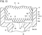
- the concave portion 36d and the convex portion 56d according to the third configuration example are described with reference to Fig. 13 .
- the distal end wall surface 30 includes an inclined surface 188 inclined in the proximal end direction from the vicinity of the outer edge of the distal end wall surface 30 to the vicinity of the communication port 32 of the female port nozzle portion 22, and the concave portion 36d is formed of an outer edge portion of the inclined surface 188.
- the concave portion 36d is concave in the distal end direction more than at least a part of the inner edge portion 34.
- the inclined surface 188 is inclined with respect to a plane orthogonal to the axis line Ax of the syringe 12.
- the concave portion 36d extends into an annular shape. Note that an annular convex portion 190 is formed on a proximal end portion of the inner peripheral surface 40 of the female port nozzle portion 22.
- the distal end face 52 of the gasket 16 includes a central convex portion 192 capable of abutting the annular convex portion 190 and an inclined surface 194 inclined in the proximal end direction from the vicinity of the outer edge of the distal end face 52 to the vicinity of the central convex portion 192, and the convex portion 56d is formed of an outer edge portion of the inclined surface 194.
- the inclined surface 194 is substantially parallel to the inclined surface 188.
- the convex portion 56d has a shape corresponding to the concave portion 36d.
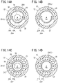
- the concave portion 36e and the convex portion 56e according to the fourth configuration example are described with reference to Figs. 14A and 14B .
- the concave portion 36e includes a first concave portion 196 adjacent to the inner edge portion 34 and a second concave portion 198 arranged radially outside the first concave portion 196.
- the first concave portion 196 extends in a range smaller than 360° in the circumferential direction of the body portion 20.
- the first concave portion 196 extends into a semi-circular shape over a range of about 180° in the circumferential direction of the body portion 20.
- the first concave portion 196 is concave in the distal end direction more than at least a part of the inner edge portion 34.
- the second concave portion 198 is arranged so as to cover an entire flat surface portion 200 adjacent to the inner edge portion 34 in which the first concave portion 196 is not formed out of the distal end wall surface 30 from radially outside. Specifically, the second concave portion 198 extends 180° or more in the circumferential direction of the body portion 20. That is, the second concave portion 198 extends in the circumferential direction of the body portion 20 such that both ends thereof are located radially outside the first concave portion 196.
- a cross-sectional shape of each of the first concave portion 196 and the second concave portion 198 may be set arbitrarily, and may be formed, for example, into the same shape as the cross-sectional shape of the concave portion 36a or the concave portion 36b described above.
- the convex portion 56e includes a first convex portion 202 insertable into the first concave portion 196 and a second convex portion 204 insertable into the second concave portion 198.
- the first convex portion 202 is arranged in a position facing the first concave portion 196
- the second convex portion 204 is arranged in a position facing the second concave portion 198.
- Cross-sectional shapes of the first convex portion 202 and the second convex portion 204 are the same as the cross-sectional shapes of the first concave portion 196 and the second concave portion 198, respectively. According to such concave portion 36e and convex portion 56e, the effects similar to those of the concave portion 36a and the convex portion 56a described above may be obtained.
- the concave portion 36f and the convex portion 56f according to the fifth configuration example are described with reference to Figs. 14C and 14D .
- the concave portion 36f includes a plurality of first concave portions 206 adjacent to the inner edge portion 34 and a plurality of second concave portions 208 arranged radially outside the first concave portions 206.
- the plurality of first concave portions 206 is arranged at intervals in the circumferential direction of the body portion 20.
- the first concave portion 206 is formed into a circular shape in planar view. However, the first concave portion 206 may also be formed into an arbitrary shape such as an elliptical shape or a polygonal shape in planar view.
- the first concave portion 206 is concave in the distal end direction more than at least a part of the inner edge portion 34.
- the plurality of second concave portions 208 is arranged at intervals in the circumferential direction of the body portion 20.
- the plurality of second concave portions 208 is arranged so as to cover a flat surface portion 210 located between the adjacent first concave portions 206 from radially outside and located radially outside the first concave portions 206 located on both sides of the flat surface portion 210.
- the second concave portion 208 may be formed into an arbitrary shape such as an elliptical shape or a polygonal shape in planar view.
- the first concave portion 206 and the second concave portion 208 may be easily formed by, for example, embossing the distal end wall surface 30 of the body portion 20.
- the convex portion 56f includes a plurality of first convex portions 212 insertable into a plurality of first concave portions 206 and a plurality of second convex portions 214 insertable into a plurality of second concave portions 208.
- the first convex portion 212 is provided in a position facing the first concave portion 206
- the second convex portion 214 is provided in a position facing the second concave portion 208.
- Cross-sectional shapes of the first convex portion 212 and the second convex portion 214 are the same as the cross-sectional shapes of the first concave portion 206 and the second concave portion 208, respectively. According to such concave portion 36f and convex portion 56f, effects similar to those of the concave portion 36a and the convex portion 56a described above may be obtained.
- the convex portions 56a to 56f of the gasket 16 may be omitted.
Landscapes
- Health & Medical Sciences (AREA)
- Veterinary Medicine (AREA)
- Life Sciences & Earth Sciences (AREA)
- Animal Behavior & Ethology (AREA)
- General Health & Medical Sciences (AREA)
- Public Health (AREA)
- Biomedical Technology (AREA)
- Vascular Medicine (AREA)
- Engineering & Computer Science (AREA)
- Anesthesiology (AREA)
- Heart & Thoracic Surgery (AREA)
- Hematology (AREA)
- Pharmacology & Pharmacy (AREA)
- Physics & Mathematics (AREA)
- Fluid Mechanics (AREA)
- Infusion, Injection, And Reservoir Apparatuses (AREA)
- Medical Preparation Storing Or Oral Administration Devices (AREA)
Claims (13)
- Seringue (12) comprenant :une partie de corps (20) comprenant une cavité interne (19) pouvant être remplie avec une solution médicinale ; une partie de buse à orifice femelle (22) qui s'étend d'une extrémité distale de la partie de corps dans laquelle est inséré un raccord Luer mâle ; et une ouverture d'extrémité proximale (24) formée sur une partie d'extrémité proximale de la partie de corps,dans laquelle la partie de buse à orifice femelle comprend un orifice de communication (32) par le biais duquel la partie de buse à orifice femelle est en communication avec la cavité interne de la partie de corps sur une extrémité proximale de la partie de buse à orifice femelle,la partie de corps comprend :une surface de paroi d'extrémité distale (30) qui s'étend radialement vers l'extérieur à partir de l'orifice de communication de la partie de buse à orifice femelle et fait face à la cavité interne, etune surface de paroi latérale (28) qui s'étend à partir d'un bord externe de la surface de paroi d'extrémité distale dans une direction d'extrémité proximale et fait face à la cavité interne,la surface de paroi d'extrémité distale de la partie de corps comprend :une partie de bord interne (34) adjacente à l'orifice de communication de la partie de buse à orifice femelle, etdans laquelle un lubrifiant liquide (L) est appliqué sur la surface de paroi latérale de la partie de corps,caractérisée en ce que :la seringue comprend en outre une partie concave (36a) agencée radialement à l'extérieur de la partie de bord interne et est davantage concave dans une direction d'extrémité distale qu'au moins une partie de la partie de bord interne,dans laquelle :
la partie concave de la surface de paroi d'extrémité distale est agencée afin d'entourer complètement l'orifice de communication de la partie de buse à orifice femelle et peut stocker le lubrifiant liquide. - Seringue selon la revendication 1,
dans laquelle la partie concave comprend :une première partie concave adjacente à la partie de bord interne, etune seconde partie concave agencée radialement à l'extérieur de la première partie concave. - Seringue selon la revendication 1,dans laquelle la surface de paroi d'extrémité distale comprend une surface inclinée, inclinée dans la direction d'extrémité proximale à partir de la proximité du bord externe de la surface de paroi d'extrémité distale jusqu'à la proximité de l'orifice de communication de la partie de buse à orifice femelle, etla partie concave est formée avec une partie de bord externe de la surface inclinée.
- Seringue selon la revendication 2,dans laquelle chacune parmi la première partie concave et la seconde partie concave s'étend sur une plage inférieure à 360° dans une direction circonférentielle de la partie de corps, etla seconde partie concave est agencée afin de recouvrir toute une partie de surface plate adjacente à la partie de bord interne dans laquelle la première partie concave n'est pas formée avec la surface de paroi d'extrémité distale radialement depuis l'extérieur.
- Seringue selon la revendication 4,dans laquelle chacune d'une pluralité de premières parties concaves et d'une pluralité de secondes parties concaves est agencée à intervalles dans la direction circonférentielle de la partie de corps, etles secondes parties concaves sont agencées afin de recouvrir la partie de surface plate située entre les premières parties concaves adjacentes entre elles radialement depuis l'extérieur.
- Seringue selon l'une quelconque des revendications 1 à 5,
dans laquelle le lubrifiant liquide n'est sensiblement pas appliqué sur une surface périphérique interne de la partie de buse à orifice femelle. - Ensemble de seringue comprenant :la seringue selon l'une quelconque des revendications 1 à 6 ; etun joint (16) agencé dans la partie de corps de la seringue et pouvant coulisser sur la surface de paroi latérale de la partie de corps,dans lequel la surface de paroi d'extrémité distale de la partie de corps comprend une partie de bord externe entre la partie concave et le bord externe, etle joint comprend une face d'extrémité distale pouvant venir en butée contre la partie de bord externe de la surface de paroi d'extrémité distale.
- Ensemble de seringue selon la revendication 7,
dans lequel la face d'extrémité distale du joint comprend une partie convexe (56a) pouvant être insérée dans la partie concave de la surface de paroi d'extrémité distale de la partie de corps. - Ensemble de seringue selon la revendication 8,
dans lequel une partie faisant face à la surface de paroi d'extrémité distale hors de la face d'extrémité distale du joint a sensiblement la même forme qu'une forme de la surface de paroi d'extrémité distale de la partie de corps. - Ensemble de seringue selon l'une quelconque des revendications 7 à 9,
dans lequel la face d'extrémité distale du joint est configurée pour venir en butée contre la partie de bord externe de la surface de paroi d'extrémité distale de la partie de corps avant de venir en butée contre la partie de bord interne de la surface de paroi d'extrémité distale de la partie de corps, lorsque le joint est déplacé dans la direction d'extrémité distale par rapport à la partie de corps. - Procédé pour fabriquer une seringue prévue avec une partie de corps comprenant une cavité interne pouvant être remplie avec une solution médicinale, une partie de buse à orifice femelle qui s'étend à partir d'une extrémité distale de la partie de corps dans laquelle est inséré un raccord Luer, et une ouverture d'extrémité proximale formée sur une partie d'extrémité proximale de la partie de corps, le procédé comprenant les étapes consistant à :
préparer la seringue dans laquelle la partie de buse à orifice femelle comprend un orifice de communication par le biais duquel une partie interne de la partie de buse à orifice femelle est en communication avec la cavité interne de la partie de corps sur une extrémité proximale de la partie de buse à orifice femelle, la partie de corps comprend une surface de paroi d'extrémité distale qui s'étend radialement vers l'extérieur à partir de l'orifice de communication de la partie de buse à orifice femelle et fait face à la cavité interne, et une surface de paroi latérale qui s'étend à partir d'un bord externe de la surface de paroi d'extrémité distale dans une direction d'extrémité proximale et fait face à la cavité interne, et la surface de paroi d'extrémité distale de la partie de corps comprend :une partie de bord interne adjacente à l'orifice de communication de la partie de buse à orifice femelle, et une partie concave agencée radialement à l'extérieur de la partie de bord interne afin d'entourer complètement l'orifice de communication de la partie de buse à orifice femelle et est davantage concave dans une direction d'extrémité distale qu'au moins une partie de la partie de bord interne ;appliquer un lubrifiant liquide sur la surface de paroi latérale de la partie de corps ; etmaintenir la seringue dans un état dans lequel une extrémité distale de la partie de buse à orifice femelle est orientée vers le bas et stocker une partie du lubrifiant liquide appliqué sur la surface de paroi latérale de la partie de corps dans la partie concave de la surface de paroi d'extrémité distale. - Procédé pour fabriquer une seringue selon la revendication 11,
dans lequel le lubrifiant liquide est stocké dans la partie concave de la surface de paroi d'extrémité distale, de sorte que le lubrifiant liquide n'est sensiblement pas appliqué sur une surface périphérique interne de la partie de buse à orifice femelle. - Procédé pour fabriquer une seringue selon la revendication 12, comprenant les étapes consistant à :préparer un récipient de stockage qui stocke la seringue ; etmaintenir la seringue dans le récipient de stockage dans un état dans lequel l'extrémité distale de la partie de buse à orifice femelle est orientée vers le bas.
Applications Claiming Priority (2)
| Application Number | Priority Date | Filing Date | Title |
|---|---|---|---|
| JP2018066367 | 2018-03-30 | ||
| PCT/JP2019/013236 WO2019189385A1 (fr) | 2018-03-30 | 2019-03-27 | Seringue, ensemble de seringue et procédé de fabrication de seringue |
Publications (3)
| Publication Number | Publication Date |
|---|---|
| EP3760255A1 EP3760255A1 (fr) | 2021-01-06 |
| EP3760255A4 EP3760255A4 (fr) | 2021-05-19 |
| EP3760255B1 true EP3760255B1 (fr) | 2022-07-13 |
Family
ID=68059054
Family Applications (1)
| Application Number | Title | Priority Date | Filing Date |
|---|---|---|---|
| EP19775174.6A Active EP3760255B1 (fr) | 2018-03-30 | 2019-03-27 | Seringue, ensemble de seringue et procédé de fabrication de seringue |
Country Status (4)
| Country | Link |
|---|---|
| US (1) | US12194281B2 (fr) |
| EP (1) | EP3760255B1 (fr) |
| JP (1) | JP7110326B2 (fr) |
| WO (1) | WO2019189385A1 (fr) |
Families Citing this family (3)
| Publication number | Priority date | Publication date | Assignee | Title |
|---|---|---|---|---|
| CN111686326B (zh) | 2019-03-12 | 2024-04-26 | 泰尔茂株式会社 | 治疗方法、分离方法及过滤器组装体 |
| JP7333282B2 (ja) * | 2020-02-27 | 2023-08-24 | テルモ株式会社 | 医療用具梱包体 |
| CN119855576A (zh) * | 2022-09-16 | 2025-04-18 | 舒万诺知识产权公司 | 具有降低的挤出力的牙科产品 |
Family Cites Families (9)
| Publication number | Priority date | Publication date | Assignee | Title |
|---|---|---|---|---|
| US7144389B2 (en) | 2001-03-14 | 2006-12-05 | Tyco Healthcare Group, Lp | Safety shield for medical needles |
| JP2007117272A (ja) * | 2005-10-26 | 2007-05-17 | Vekuson:Kk | キット製剤用注射器、注射器型キット製剤用中間摺動弁、及び、注射器型キット製剤、並びにキット製剤用注射筒の製造方法 |
| US20070129676A1 (en) * | 2005-12-05 | 2007-06-07 | Hsiu-Chih Lin | Safe syringe |
| JP5936859B2 (ja) | 2011-12-26 | 2016-06-22 | 株式会社大協精工 | 二薬混合用シリンジキット |
| JP5976921B2 (ja) | 2013-03-15 | 2016-08-24 | テルモ株式会社 | シリンジ用組立体、シリンジ用組立体包装体およびプレフィルドシリンジ |
| WO2015006444A1 (fr) * | 2013-07-10 | 2015-01-15 | Merit Medical Systems, Inc. | Seringues pré-remplies et procédés associés |
| ITRM20130457A1 (it) * | 2013-08-05 | 2015-02-06 | Orofino Pharmaceuticals Group Srl | Prodotto intermedio per la realizzazione di siringhe o cartucce a doppia camera pre-riempite e procedimento di produzione di detto prodotto intermedio |
| EP3378514B1 (fr) | 2015-11-19 | 2025-09-10 | Terumo Kabushiki Kaisha | Cylindre pour seringue, seringue préremplie, et procédés de fabrication de ceux-ci |
| US20180333539A1 (en) * | 2017-05-18 | 2018-11-22 | Sheng Yang International Technology Co., Ltd. | Safety syringe structure |
-
2019
- 2019-03-27 EP EP19775174.6A patent/EP3760255B1/fr active Active
- 2019-03-27 JP JP2020509205A patent/JP7110326B2/ja not_active Expired - Fee Related
- 2019-03-27 WO PCT/JP2019/013236 patent/WO2019189385A1/fr not_active Ceased
-
2020
- 2020-09-30 US US17/038,845 patent/US12194281B2/en active Active
Also Published As
| Publication number | Publication date |
|---|---|
| JP7110326B2 (ja) | 2022-08-01 |
| WO2019189385A1 (fr) | 2019-10-03 |
| US12194281B2 (en) | 2025-01-14 |
| US20210008285A1 (en) | 2021-01-14 |
| EP3760255A1 (fr) | 2021-01-06 |
| EP3760255A4 (fr) | 2021-05-19 |
| JPWO2019189385A1 (ja) | 2021-03-25 |
Similar Documents
| Publication | Publication Date | Title |
|---|---|---|
| US9623171B2 (en) | Medical device package | |
| TWI586349B (zh) | 用於注射液體的插入物及藥瓶、用於注射液體的藥瓶插入物總成以及用於從藥瓶將液體轉移至另一容器的方法 | |
| EP0554988B1 (fr) | Dispositif pour mélanger | |
| US4865592A (en) | Container and needle assembly | |
| US8522975B2 (en) | Syringe assembly and package for distribution of same | |
| CN104602740B (zh) | 注射器用组装体、注射器用组装体包装体以及预灌封注射器 | |
| US12194281B2 (en) | Syringe, syringe assembly, and manufacturing method of syringe | |
| JP6457930B2 (ja) | シリンジ用組立体、シリンジ用組立体包装体およびプレフィルドシリンジ | |
| US20080302697A1 (en) | Dual pack container | |
| CN108290006B (zh) | 注射器用筒体、预灌封注射器及它们的制造方法 | |
| WO2023147491A2 (fr) | Système d'emballage pour le stockage d'un produit périssable | |
| WO2014049781A1 (fr) | Tube pour seringue pré-remplie, dispositif de perforation pour seringue pré-remplie, seringue pré-remplie et corps d'emballage de tube pour seringue pré-remplie | |
| WO2017158805A1 (fr) | Ensemble seringue, emballage d'ensemble seringue et seringue pré-remplie | |
| JPWO2019111938A1 (ja) | ポート付バッグおよびキャップ付バッグ | |
| WO2022187332A1 (fr) | Récipient pour composition pharmaceutique | |
| KR102274243B1 (ko) | 어댑터를 의료 용기와 결합시키기 위한 조립체 | |
| JPH04221567A (ja) | 医療用容器 | |
| WO2016196632A1 (fr) | Accessoire à deux accès pour contenant | |
| JP2004033442A (ja) | シリンジ | |
| JP3313807B2 (ja) | 注射器、注射器用容器および注射器本体 | |
| JP6318691B2 (ja) | 医療用栓体 | |
| WO2012117622A1 (fr) | Seringue pré-remplie et procédé de fabrication d'une seringue pré-remplie | |
| JPH09108302A (ja) | 医療用容器及びその製造方法 | |
| JPH08238314A (ja) | 注射器 | |
| JPH11104213A (ja) | 薬剤容器のキャップ |
Legal Events
| Date | Code | Title | Description |
|---|---|---|---|
| STAA | Information on the status of an ep patent application or granted ep patent |
Free format text: STATUS: THE INTERNATIONAL PUBLICATION HAS BEEN MADE |
|
| PUAI | Public reference made under article 153(3) epc to a published international application that has entered the european phase |
Free format text: ORIGINAL CODE: 0009012 |
|
| STAA | Information on the status of an ep patent application or granted ep patent |
Free format text: STATUS: REQUEST FOR EXAMINATION WAS MADE |
|
| 17P | Request for examination filed |
Effective date: 20201001 |
|
| AK | Designated contracting states |
Kind code of ref document: A1 Designated state(s): AL AT BE BG CH CY CZ DE DK EE ES FI FR GB GR HR HU IE IS IT LI LT LU LV MC MK MT NL NO PL PT RO RS SE SI SK SM TR |
|
| AX | Request for extension of the european patent |
Extension state: BA ME |
|
| A4 | Supplementary search report drawn up and despatched |
Effective date: 20210415 |
|
| RIC1 | Information provided on ipc code assigned before grant |
Ipc: A61M 5/31 20060101AFI20210412BHEP Ipc: A61J 1/20 20060101ALI20210412BHEP Ipc: A61M 5/00 20060101ALI20210412BHEP Ipc: A61M 5/315 20060101ALI20210412BHEP Ipc: A61M 5/28 20060101ALI20210412BHEP |
|
| DAV | Request for validation of the european patent (deleted) | ||
| DAX | Request for extension of the european patent (deleted) | ||
| GRAP | Despatch of communication of intention to grant a patent |
Free format text: ORIGINAL CODE: EPIDOSNIGR1 |
|
| STAA | Information on the status of an ep patent application or granted ep patent |
Free format text: STATUS: GRANT OF PATENT IS INTENDED |
|
| INTG | Intention to grant announced |
Effective date: 20220401 |
|
| GRAS | Grant fee paid |
Free format text: ORIGINAL CODE: EPIDOSNIGR3 |
|
| GRAA | (expected) grant |
Free format text: ORIGINAL CODE: 0009210 |
|
| STAA | Information on the status of an ep patent application or granted ep patent |
Free format text: STATUS: THE PATENT HAS BEEN GRANTED |
|
| AK | Designated contracting states |
Kind code of ref document: B1 Designated state(s): AL AT BE BG CH CY CZ DE DK EE ES FI FR GB GR HR HU IE IS IT LI LT LU LV MC MK MT NL NO PL PT RO RS SE SI SK SM TR |
|
| REG | Reference to a national code |
Ref country code: CH Ref legal event code: EP |
|
| REG | Reference to a national code |
Ref country code: DE Ref legal event code: R096 Ref document number: 602019017044 Country of ref document: DE |
|
| REG | Reference to a national code |
Ref country code: AT Ref legal event code: REF Ref document number: 1503932 Country of ref document: AT Kind code of ref document: T Effective date: 20220815 |
|
| REG | Reference to a national code |
Ref country code: IE Ref legal event code: FG4D |
|
| REG | Reference to a national code |
Ref country code: LT Ref legal event code: MG9D |
|
| REG | Reference to a national code |
Ref country code: NL Ref legal event code: MP Effective date: 20220713 |
|
| PG25 | Lapsed in a contracting state [announced via postgrant information from national office to epo] |
Ref country code: SE Free format text: LAPSE BECAUSE OF FAILURE TO SUBMIT A TRANSLATION OF THE DESCRIPTION OR TO PAY THE FEE WITHIN THE PRESCRIBED TIME-LIMIT Effective date: 20220713 Ref country code: RS Free format text: LAPSE BECAUSE OF FAILURE TO SUBMIT A TRANSLATION OF THE DESCRIPTION OR TO PAY THE FEE WITHIN THE PRESCRIBED TIME-LIMIT Effective date: 20220713 Ref country code: PT Free format text: LAPSE BECAUSE OF FAILURE TO SUBMIT A TRANSLATION OF THE DESCRIPTION OR TO PAY THE FEE WITHIN THE PRESCRIBED TIME-LIMIT Effective date: 20221114 Ref country code: NO Free format text: LAPSE BECAUSE OF FAILURE TO SUBMIT A TRANSLATION OF THE DESCRIPTION OR TO PAY THE FEE WITHIN THE PRESCRIBED TIME-LIMIT Effective date: 20221013 Ref country code: NL Free format text: LAPSE BECAUSE OF FAILURE TO SUBMIT A TRANSLATION OF THE DESCRIPTION OR TO PAY THE FEE WITHIN THE PRESCRIBED TIME-LIMIT Effective date: 20220713 Ref country code: LV Free format text: LAPSE BECAUSE OF FAILURE TO SUBMIT A TRANSLATION OF THE DESCRIPTION OR TO PAY THE FEE WITHIN THE PRESCRIBED TIME-LIMIT Effective date: 20220713 Ref country code: LT Free format text: LAPSE BECAUSE OF FAILURE TO SUBMIT A TRANSLATION OF THE DESCRIPTION OR TO PAY THE FEE WITHIN THE PRESCRIBED TIME-LIMIT Effective date: 20220713 Ref country code: FI Free format text: LAPSE BECAUSE OF FAILURE TO SUBMIT A TRANSLATION OF THE DESCRIPTION OR TO PAY THE FEE WITHIN THE PRESCRIBED TIME-LIMIT Effective date: 20220713 Ref country code: ES Free format text: LAPSE BECAUSE OF FAILURE TO SUBMIT A TRANSLATION OF THE DESCRIPTION OR TO PAY THE FEE WITHIN THE PRESCRIBED TIME-LIMIT Effective date: 20220713 |
|
| REG | Reference to a national code |
Ref country code: AT Ref legal event code: MK05 Ref document number: 1503932 Country of ref document: AT Kind code of ref document: T Effective date: 20220713 |
|
| PG25 | Lapsed in a contracting state [announced via postgrant information from national office to epo] |
Ref country code: PL Free format text: LAPSE BECAUSE OF FAILURE TO SUBMIT A TRANSLATION OF THE DESCRIPTION OR TO PAY THE FEE WITHIN THE PRESCRIBED TIME-LIMIT Effective date: 20220713 Ref country code: IS Free format text: LAPSE BECAUSE OF FAILURE TO SUBMIT A TRANSLATION OF THE DESCRIPTION OR TO PAY THE FEE WITHIN THE PRESCRIBED TIME-LIMIT Effective date: 20221113 Ref country code: HR Free format text: LAPSE BECAUSE OF FAILURE TO SUBMIT A TRANSLATION OF THE DESCRIPTION OR TO PAY THE FEE WITHIN THE PRESCRIBED TIME-LIMIT Effective date: 20220713 Ref country code: GR Free format text: LAPSE BECAUSE OF FAILURE TO SUBMIT A TRANSLATION OF THE DESCRIPTION OR TO PAY THE FEE WITHIN THE PRESCRIBED TIME-LIMIT Effective date: 20221014 |
|
| REG | Reference to a national code |
Ref country code: DE Ref legal event code: R097 Ref document number: 602019017044 Country of ref document: DE |
|
| PG25 | Lapsed in a contracting state [announced via postgrant information from national office to epo] |
Ref country code: SM Free format text: LAPSE BECAUSE OF FAILURE TO SUBMIT A TRANSLATION OF THE DESCRIPTION OR TO PAY THE FEE WITHIN THE PRESCRIBED TIME-LIMIT Effective date: 20220713 Ref country code: RO Free format text: LAPSE BECAUSE OF FAILURE TO SUBMIT A TRANSLATION OF THE DESCRIPTION OR TO PAY THE FEE WITHIN THE PRESCRIBED TIME-LIMIT Effective date: 20220713 Ref country code: DK Free format text: LAPSE BECAUSE OF FAILURE TO SUBMIT A TRANSLATION OF THE DESCRIPTION OR TO PAY THE FEE WITHIN THE PRESCRIBED TIME-LIMIT Effective date: 20220713 Ref country code: CZ Free format text: LAPSE BECAUSE OF FAILURE TO SUBMIT A TRANSLATION OF THE DESCRIPTION OR TO PAY THE FEE WITHIN THE PRESCRIBED TIME-LIMIT Effective date: 20220713 Ref country code: AT Free format text: LAPSE BECAUSE OF FAILURE TO SUBMIT A TRANSLATION OF THE DESCRIPTION OR TO PAY THE FEE WITHIN THE PRESCRIBED TIME-LIMIT Effective date: 20220713 |
|
| PLBE | No opposition filed within time limit |
Free format text: ORIGINAL CODE: 0009261 |
|
| STAA | Information on the status of an ep patent application or granted ep patent |
Free format text: STATUS: NO OPPOSITION FILED WITHIN TIME LIMIT |
|
| PG25 | Lapsed in a contracting state [announced via postgrant information from national office to epo] |
Ref country code: SK Free format text: LAPSE BECAUSE OF FAILURE TO SUBMIT A TRANSLATION OF THE DESCRIPTION OR TO PAY THE FEE WITHIN THE PRESCRIBED TIME-LIMIT Effective date: 20220713 Ref country code: EE Free format text: LAPSE BECAUSE OF FAILURE TO SUBMIT A TRANSLATION OF THE DESCRIPTION OR TO PAY THE FEE WITHIN THE PRESCRIBED TIME-LIMIT Effective date: 20220713 |
|
| 26N | No opposition filed |
Effective date: 20230414 |
|
| PG25 | Lapsed in a contracting state [announced via postgrant information from national office to epo] |
Ref country code: AL Free format text: LAPSE BECAUSE OF FAILURE TO SUBMIT A TRANSLATION OF THE DESCRIPTION OR TO PAY THE FEE WITHIN THE PRESCRIBED TIME-LIMIT Effective date: 20220713 |
|
| PG25 | Lapsed in a contracting state [announced via postgrant information from national office to epo] |
Ref country code: SI Free format text: LAPSE BECAUSE OF FAILURE TO SUBMIT A TRANSLATION OF THE DESCRIPTION OR TO PAY THE FEE WITHIN THE PRESCRIBED TIME-LIMIT Effective date: 20220713 |
|
| PG25 | Lapsed in a contracting state [announced via postgrant information from national office to epo] |
Ref country code: MC Free format text: LAPSE BECAUSE OF FAILURE TO SUBMIT A TRANSLATION OF THE DESCRIPTION OR TO PAY THE FEE WITHIN THE PRESCRIBED TIME-LIMIT Effective date: 20220713 |
|
| REG | Reference to a national code |
Ref country code: CH Ref legal event code: PL |
|
| REG | Reference to a national code |
Ref country code: BE Ref legal event code: MM Effective date: 20230331 |
|
| PG25 | Lapsed in a contracting state [announced via postgrant information from national office to epo] |
Ref country code: LU Free format text: LAPSE BECAUSE OF NON-PAYMENT OF DUE FEES Effective date: 20230327 |
|
| REG | Reference to a national code |
Ref country code: IE Ref legal event code: MM4A |
|
| PG25 | Lapsed in a contracting state [announced via postgrant information from national office to epo] |
Ref country code: LI Free format text: LAPSE BECAUSE OF NON-PAYMENT OF DUE FEES Effective date: 20230331 Ref country code: IT Free format text: LAPSE BECAUSE OF FAILURE TO SUBMIT A TRANSLATION OF THE DESCRIPTION OR TO PAY THE FEE WITHIN THE PRESCRIBED TIME-LIMIT Effective date: 20220713 Ref country code: IE Free format text: LAPSE BECAUSE OF NON-PAYMENT OF DUE FEES Effective date: 20230327 Ref country code: CH Free format text: LAPSE BECAUSE OF NON-PAYMENT OF DUE FEES Effective date: 20230331 |
|
| PG25 | Lapsed in a contracting state [announced via postgrant information from national office to epo] |
Ref country code: BE Free format text: LAPSE BECAUSE OF NON-PAYMENT OF DUE FEES Effective date: 20230331 |
|
| PG25 | Lapsed in a contracting state [announced via postgrant information from national office to epo] |
Ref country code: BG Free format text: LAPSE BECAUSE OF FAILURE TO SUBMIT A TRANSLATION OF THE DESCRIPTION OR TO PAY THE FEE WITHIN THE PRESCRIBED TIME-LIMIT Effective date: 20220713 |
|
| PG25 | Lapsed in a contracting state [announced via postgrant information from national office to epo] |
Ref country code: BG Free format text: LAPSE BECAUSE OF FAILURE TO SUBMIT A TRANSLATION OF THE DESCRIPTION OR TO PAY THE FEE WITHIN THE PRESCRIBED TIME-LIMIT Effective date: 20220713 |
|
| PGFP | Annual fee paid to national office [announced via postgrant information from national office to epo] |
Ref country code: DE Payment date: 20250128 Year of fee payment: 7 |
|
| PGFP | Annual fee paid to national office [announced via postgrant information from national office to epo] |
Ref country code: FR Payment date: 20250210 Year of fee payment: 7 |
|
| PGFP | Annual fee paid to national office [announced via postgrant information from national office to epo] |
Ref country code: GB Payment date: 20250206 Year of fee payment: 7 |
|
| PG25 | Lapsed in a contracting state [announced via postgrant information from national office to epo] |
Ref country code: CY Free format text: LAPSE BECAUSE OF FAILURE TO SUBMIT A TRANSLATION OF THE DESCRIPTION OR TO PAY THE FEE WITHIN THE PRESCRIBED TIME-LIMIT; INVALID AB INITIO Effective date: 20190327 |
|
| PG25 | Lapsed in a contracting state [announced via postgrant information from national office to epo] |
Ref country code: HU Free format text: LAPSE BECAUSE OF FAILURE TO SUBMIT A TRANSLATION OF THE DESCRIPTION OR TO PAY THE FEE WITHIN THE PRESCRIBED TIME-LIMIT; INVALID AB INITIO Effective date: 20190327 |
|
| PG25 | Lapsed in a contracting state [announced via postgrant information from national office to epo] |
Ref country code: TR Free format text: LAPSE BECAUSE OF FAILURE TO SUBMIT A TRANSLATION OF THE DESCRIPTION OR TO PAY THE FEE WITHIN THE PRESCRIBED TIME-LIMIT Effective date: 20220713 |