EP3760331A1 - Procédé de production d'éléments formés à la presse, dispositif de formage à la presse et tôle métallique pour le formage à la presse - Google Patents
Procédé de production d'éléments formés à la presse, dispositif de formage à la presse et tôle métallique pour le formage à la presse Download PDFInfo
- Publication number
- EP3760331A1 EP3760331A1 EP19760333.5A EP19760333A EP3760331A1 EP 3760331 A1 EP3760331 A1 EP 3760331A1 EP 19760333 A EP19760333 A EP 19760333A EP 3760331 A1 EP3760331 A1 EP 3760331A1
- Authority
- EP
- European Patent Office
- Prior art keywords
- press
- top sheet
- shape
- projection
- curved
- Prior art date
- Legal status (The legal status is an assumption and is not a legal conclusion. Google has not performed a legal analysis and makes no representation as to the accuracy of the status listed.)
- Pending
Links
Images


Classifications
-
- B—PERFORMING OPERATIONS; TRANSPORTING
- B21—MECHANICAL METAL-WORKING WITHOUT ESSENTIALLY REMOVING MATERIAL; PUNCHING METAL
- B21D—WORKING OR PROCESSING OF SHEET METAL OR METAL TUBES, RODS OR PROFILES WITHOUT ESSENTIALLY REMOVING MATERIAL; PUNCHING METAL
- B21D22/00—Shaping without cutting, by stamping, spinning, or deep-drawing
- B21D22/20—Deep-drawing
- B21D22/26—Deep-drawing for making peculiarly, e.g. irregularly, shaped articles
-
- B—PERFORMING OPERATIONS; TRANSPORTING
- B21—MECHANICAL METAL-WORKING WITHOUT ESSENTIALLY REMOVING MATERIAL; PUNCHING METAL
- B21D—WORKING OR PROCESSING OF SHEET METAL OR METAL TUBES, RODS OR PROFILES WITHOUT ESSENTIALLY REMOVING MATERIAL; PUNCHING METAL
- B21D53/00—Making other particular articles
- B21D53/88—Making other particular articles other parts for vehicles, e.g. cowlings, mudguards
-
- B—PERFORMING OPERATIONS; TRANSPORTING
- B21—MECHANICAL METAL-WORKING WITHOUT ESSENTIALLY REMOVING MATERIAL; PUNCHING METAL
- B21D—WORKING OR PROCESSING OF SHEET METAL OR METAL TUBES, RODS OR PROFILES WITHOUT ESSENTIALLY REMOVING MATERIAL; PUNCHING METAL
- B21D19/00—Flanging or other edge treatment, e.g. of tubes
- B21D19/08—Flanging or other edge treatment, e.g. of tubes by single or successive action of pressing tools, e.g. vice jaws
-
- B—PERFORMING OPERATIONS; TRANSPORTING
- B21—MECHANICAL METAL-WORKING WITHOUT ESSENTIALLY REMOVING MATERIAL; PUNCHING METAL
- B21D—WORKING OR PROCESSING OF SHEET METAL OR METAL TUBES, RODS OR PROFILES WITHOUT ESSENTIALLY REMOVING MATERIAL; PUNCHING METAL
- B21D22/00—Shaping without cutting, by stamping, spinning, or deep-drawing
- B21D22/02—Stamping using rigid devices or tools
-
- B—PERFORMING OPERATIONS; TRANSPORTING
- B21—MECHANICAL METAL-WORKING WITHOUT ESSENTIALLY REMOVING MATERIAL; PUNCHING METAL
- B21D—WORKING OR PROCESSING OF SHEET METAL OR METAL TUBES, RODS OR PROFILES WITHOUT ESSENTIALLY REMOVING MATERIAL; PUNCHING METAL
- B21D22/00—Shaping without cutting, by stamping, spinning, or deep-drawing
- B21D22/20—Deep-drawing
-
- B—PERFORMING OPERATIONS; TRANSPORTING
- B21—MECHANICAL METAL-WORKING WITHOUT ESSENTIALLY REMOVING MATERIAL; PUNCHING METAL
- B21D—WORKING OR PROCESSING OF SHEET METAL OR METAL TUBES, RODS OR PROFILES WITHOUT ESSENTIALLY REMOVING MATERIAL; PUNCHING METAL
- B21D24/00—Special deep-drawing arrangements in, or in connection with, presses
-
- B—PERFORMING OPERATIONS; TRANSPORTING
- B21—MECHANICAL METAL-WORKING WITHOUT ESSENTIALLY REMOVING MATERIAL; PUNCHING METAL
- B21D—WORKING OR PROCESSING OF SHEET METAL OR METAL TUBES, RODS OR PROFILES WITHOUT ESSENTIALLY REMOVING MATERIAL; PUNCHING METAL
- B21D37/00—Tools as parts of machines covered by this subclass
- B21D37/08—Dies with different parts for several steps in a process
-
- B—PERFORMING OPERATIONS; TRANSPORTING
- B21—MECHANICAL METAL-WORKING WITHOUT ESSENTIALLY REMOVING MATERIAL; PUNCHING METAL
- B21D—WORKING OR PROCESSING OF SHEET METAL OR METAL TUBES, RODS OR PROFILES WITHOUT ESSENTIALLY REMOVING MATERIAL; PUNCHING METAL
- B21D25/00—Working sheet metal of limited length by stretching, e.g. for straightening
Definitions
- the present invention is a technology relating to production of a press-formed component including a curved portion protruding toward a top sheet portion along a longitudinal direction as seen in a side view and having a hat-shaped cross-sectional shape.
- the present invention is a technology suitable for production of a vehicle frame component including a portion curved toward a top sheet portion in a side view.
- the vehicle frame component includes, for example, a top sheet portion and vertical wall portions and flange portions continuous thereto, and are shaped to include a portion curved along a longitudinal direction as seen in a side view.
- a crack or a wrinkle may be formed on a part of the component, which can cause a forming defect.
- problems may occur such as lowered dimensional accuracy due to elastic recovery in a formed product after release.
- use of a thin high strength steel sheet as a metal sheet for press forming has been increasing in order to achieve both vehicle lightweighting and collision safety.
- a press-formed component shape including a top sheet portion and vertical wall portions and flange portions continuous thereto and including, at least one place, a shape curved in such a manner as to protrude toward the top sheet portion as seen in a side view
- material shortage on the top sheet portion side may cause a crack
- material excess on flange portion sides may cause a large wrinkle.
- poor dimensional accuracy tends to occur, such as lift of end portions in the longitudinal direction of the component in a direction where the curve in the side view becomes loose (a curvature of the curve becomes small).
- PTL 1 describes a technology as countermeasures against cracks on the top sheet portion and wrinkles on the flange portions in a final component shape including, at least one place, a shape curved longitudinally in such a manner as to protrude toward the top sheet portion as seen in a side view.
- PTL 1 proposes that, by performing drawing while pinching the top sheet portion by a pad and a punch, shear deformation is caused to occur on vertical wall portions of the component, thereby eliminating material shortage on the top sheet portion and material excess on the flange portions.
- a technology described in PTL 2 is an example of a method for reducing a longitudinal tensile stress of a top sheet portion, which is a stress that causes a spring-back when released.
- the technology described in PTL 2 produces, in a first forming step, an intermediate formed product that includes a top sheet portion having a smaller curvature radius than in the final component shape to allow it to project in excess, and forms, in a second forming step, such that the top sheet portion projecting in excess in the intermediate formed product is crushed in the final component shape.
- the technology of PTL 2 takes a countermeasure to reduce the stress causing a spring-back by generating compressive stress in the longitudinal direction of the component.
- PTL 3 proposes that a first forming step produces an intermediate formed product provided with a protruding and recessed shape such that a longitudinal line length of a top sheet portion is made longer by a certain amount than that in a final component shape, thereby securing an extra line length, and a second forming step forms the intermediate formed product into the final component shape, so that no excessive tensile deformation is applied to the top sheet portion.
- the method described in PTL 1 may create shear wrinkles due to the shear deformation applied to the vertical wall portions, which may make bonding to another component difficult. Furthermore, the method described in PTL 1 is drawing by which the vertical wall portions are subjected to bending-unbending deformation, due to which the vertical walls of the high strength steel sheet are significantly warped, leading to poor dimensional accuracy.
- the methods described in PTL 2 and PTL 3 can reduce the longitudinal tensile stress applied to the top sheet portion. However, it is necessary to provide a recessed shape to the top sheet portion, so that the shape of the component may be changed. Furthermore, the methods described in PTL 2 and PTL 3 have no effect of suppressing opening in the cross-sectional direction, thus limiting improvement in dimensional accuracy.
- the present invention has been made in view of the above problems, and it is an object of the present invention to provide a technology for producing a press-formed component, which is capable of producing, with reduced forming defects such as cracks, wrinkles, and lowered dimensional accuracy, a press-formed component having a shape including, at least one place, a shape curved in such a manner as to protrude toward a top sheet portion along a longitudinal direction as seen in a side view.
- the inventors conducted intensive studies about a press forming method capable of forming, without any cracks and wrinkles, a final component shape that includes a top sheet portion and vertical wall portions and flange portions continuous to the top sheet portion and that includes, at least one place, a shape curved in such a manner as to protrude toward the top sheet portion as seen in a side view, and also capable of suppressing spring-back.
- the present invention has been made on the basis of such a finding.
- a method for producing a press-formed component is a method for producing a press-formed component for producing, by press forming a metal sheet, a press-formed component having a press-formed component shape that has a hat-shaped cross-sectional shape including a vertical wall portion and a flange portion on both sides of a widthwise direction of a top sheet portion and that includes, at one or more places along a longitudinal direction of the top sheet portion, a curved portion curved in such a manner as to form a protrusion toward the top sheet portion as seen in a side view, the method including: a first forming step of press forming the metal sheet into an intermediate formed product that has a shape such that, as seen in a side view, a region to be the curved portion is bent out of a plane in a direction of the protrusion at a bending position set at a center portion in the longitudinal direction of the region to be the curved portion and that includes a projection portion formed by projecting
- a press forming device is a press forming device for use in the second forming step of the method for producing a press-formed component according to the one aspect of the present invention, the press forming device including an upper die including bending blades for bending the metal sheet at ridge line portion positions to perform bending of the vertical wall portion and the flange portion and a lower die including a punch, in which the bending blades are configured to move at an angle selected from a range of from 0 degrees to 90 degrees with respect to a pressing direction to perform the bending.
- a metal sheet for press forming is a metal sheet for press forming to be formed into a press-formed component shape that has a hat-shaped cross-sectional shape including a vertical wall portion and a flange portion on both sides of a widthwise direction of a top sheet portion and that includes, at one or more places along a longitudinal direction of the top sheet portion, a curved portion curved in such a manner as to form a protrusion toward the top sheet portion in a side view, the metal sheet having a shape such that, as seen in the side view, a region to be the curved portion is bent out of a plane in a direction of the protrusion at a bending position set at a center portion in the longitudinal direction of the region to be the curved portion, and including a projection portion formed by projecting regions to be the top sheet portion and the vertical wall portion in the direction of the protrusion with respect to a region to be the flange portion, in which, in the region to be the flange
- forming defects such as cracks, wrinkles, and lowered dimensional accuracy can be reduced in the production of a press-formed component having a hat-shaped cross-sectional shape and including, at least one place, a shape curved in such a manner as to protrude toward a top sheet portion along a longitudinal direction as seen in a side view.
- An example of a forming defect due to lowered dimensional accuracy is a spring-back caused by, for example, a longitudinal stress difference between the top sheet portion and the flange portions. According to the aspects of the present invention, such a spring-back can be suppressed to small.
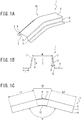
- a metal sheet 10 is press formed into a final component shape (a press-formed component shape 1) that has a hat-shaped cross-sectional shape including a top sheet portion 2 and a vertical wall portion 3 and a flange portion 4 respectively continuous on both sides of a widthwise direction of the top sheet portion 2 and that includes, at one place, a curved portion 1A curved in such a manner as to form a protrusion toward the top sheet portion 2 along a longitudinal direction of the top sheet portion 2 as seen in a side view.
- the present invention is not limited to the shape including, at only one place, the curved portion 1A curved in such a manner as to form a protrusion toward the top sheet portion 2 as seen in the side view, as illustrated in FIG. 1 .
- the present invention is also a technology effective on composite component shapes including both a curved shape protruding toward the top sheet portion 2 and a curved shape protruding toward the flange portions and component shapes including the curved portion 1A protruding toward the top sheet portion 2 at two or more places along the longitudinal direction.
- FIG. 2 illustrates examples of the press-formed component shape to which the present invention can be applied.
- the shape of the metal sheet for use in press forming of the present embodiment is not particularly limited, and for example, a metal sheet having a developed shape of the final press-formed component shape 1 developed on a plane or a metal sheet having a simple rectangular shape is used.
- the material of the metal sheet is also not particularly limited.
- the present embodiment is suitably effective on a metal sheet made of a high strength material, particularly, a steel material having a material tensile strength of 590 MPa or more.
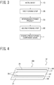
- a method for producing a press-formed component according to the present embodiment includes a first forming step 9A and a second forming step 9B, as illustrated in FIG. 3 . Since the present embodiment uses the rectangular sheet material as the metal sheet 10, a trimming step is included after the second forming step 9B. When using a sheet material having the developed shape as the metal sheet 10, the trimming step is not necessarily required.
- the method may include, as processing before the second forming step 9B, a ridge line pre-processing step of forming a bead shape or a crease shape at least one position of positions corresponding to ridge lines on the metal sheet 10. Specifically, as illustrated in FIG.
- the ridge line pre-processing step is a step of forming, at least one position of a position corresponding to a ridge line 6 between the top sheet portion 2 and the vertical wall portion 3 and a position corresponding to a ridge line 7 between the vertical wall portion 3 and the flange portion 4, at least one bead shape 20, 21 or crease shape is formed that extends in a direction along the corresponding ridge line 6, 7.
- the ridge line pre-processing step may be performed in the first forming step 9A or may be set as a separate step before or after the first forming step 9A.
- FIG. 4 illustrates an example provided with the bead shape
- a crease shape may be provided as described above, instead of the bead shape 20, 21.
- the bead shape 20, 21 and the crease shape may be used in combination in such a manner that the bead shape 20, 21 is provided at a part, and the crease shape is provided at the other part.
- only some of the ridge lines 6, 7 located at the positions of the ridge line 6, 7 may be formed with the bead shape 20, 21.
- the bead shape or crease shape does not have to be formed over the entire length of one ridge line 6, 7, and may be formed intermittently along the position of the ridge line 6, 7.
- a forming step for, for example, restrike may be added as a step subsequent to the second forming step 9B.
- the first forming step 9A is a step of performing stretch forming on the flat metal sheet 10 to obtain an intermediate formed product 30 as the metal sheet 10 to be used in the second forming step 9B.
- the metal sheet 10 is press formed into the intermediate formed product 30 that has a shape such that, as seen in a side view, at a bending position 31 set at a center portion in the longitudinal direction of a region to be the curved portion 1A forming a protrusion toward the top sheet portion 2, the region to be the curved portion 1A is bent out of a plane in a direction of the protrusion and that includes a projection portion 30A formed by stretch forming.
- the shape of the projection portion 30A is a shape such that regions to be the top sheet portion 2 and the vertical wall portion 3 (a top sheet portion forming position 12 and a vertical wall portion forming position 13) project in the direction of the protrusion relatively with respect to a region to be the flange portion 4 (a flange portion forming position 14).
- an angle of the projection along the longitudinal direction on a widthwise center portion side is smaller than an angle of the projection along the longitudinal direction on a widthwise end portion side (a side where the region to be the flange portion is located), as seen in the side view.
- an angle ⁇ to be bent out of the plane (an out-of-plane bending angle ⁇ ) in the region to be the flange portion 4 (the flange portion forming position 14) is set to equal to an angle ⁇ (see FIG. 1C ) formed by the flange portion 4 at the curved portion 1A in the press-formed component shape 1, as seen in the side view.
- the out-of-plane bending angle ⁇ may be smaller than the angle ⁇ formed by the flange portion 4 at the curved portion 1A in the press-formed component shape 1, as seen in the side view (see FIG. 6 ).
- a lower limit value of the out-of-plane bending angle ⁇ is a larger angle than an angle at which a crack is assumed to occur due to the bending, and the angle ⁇ is, for example, 90 degrees or more.
- the out-of-plane bending angle ⁇ is an angle on the side where the flange portion 4 is located, and thus is an obtuse angle of less than 180 degrees.
- the projection portion 30A has a shape such that, as seen in the side view, a height of projection decreases from the center portion of the longitudinal direction in the region to be the curved portion 1A toward the longitudinal direction as being further away from the center portion (see FIGS. 5 and 6 ).
- the projection height at the center portion (position P1) of the longitudinal direction in the region to be the curved portion 1A is the largest.
- the projection height is based on the flange portion forming position 14, and is defined, for example, as a height in a direction from the position of the flange portion forming position 14 toward a perpendicular direction.
- the height may be a height in a vertical direction.
- the shape of the projection portion 30A is set such that a difference between a longitudinal length in the region to be the top sheet portion 2 and a longitudinal length of the top sheet portion 2 in the desired press-formed component shape 1 is equal to or less than 10% of the longitudinal length of the top sheet portion 2 in the press-formed component shape 1.
- the present embodiment is designed such that the difference between the lengths is zero.
- the top sheet portion forming position 12 in the projection portion 30A is also designed to be the same (flat) in shape in the widthwise direction.
- the projection height at the vertical wall portion forming position 13 in the projection portion 30A is set so as to be an inclined surface such that the projection height gradually increases from the flange portion forming position 14 toward the top sheet portion forming position 12 along the widthwise direction (see FIGS. 5 and 6 ).
- a formation position of the projection portion 30A along the longitudinal direction is preferably formed in such a manner as to not only include the region to be the curved portion 1A but also extend to a position to be a linear portion on both sides of the longitudinal direction of the projection portion 30A.
- the projection height that is based on the flange portion forming position 14 and is along the longitudinal direction at the top sheet portion forming position 12 in the projection portion 30A as seen in the side view will be set as follows:
- the projection height at the projection vertex P1 located at the center portion in the longitudinal direction of the region to be the curved portion 1A is defined as h (mm);
- the projection height at an end point P2 set at the end portions in the longitudinal direction of the metal sheet 10 is defined as 0 (mm) ;
- the projection height at an intermediate point P3 between the projection vertex P1 and the end point P2 on left and right is defined as h' (mm).
- the intermediate point P3 is present on a perpendicular line from a midpoint at the flange portion forming position.
- a curve smoothly connecting the above-mentioned projection vertex P1, intermediate points P3, and end points P2 is defined as the profile 30Aa at the top sheet portion forming position 12 of the projection portion 30A as seen in the side view.
- the curve of the profile 30Aa is, for example, a spline curve.
- the projection heights h and h' are calculated such that the difference between the longitudinal length in the region to be the top sheet portion 2 (the top sheet portion forming position 12) and the longitudinal length of the top sheet portion 2 in the desired press-formed component shape 1 becomes zero.
- the projection height h' at the intermediate point P3 is preferably set to satisfy the following expression (1): 1 / 3 ⁇ h ⁇ h ′ ⁇ 1 / 2 ⁇ h
- Each end point P2 to be set may be set at a position closer to the projection vertex P1 side rather than the end portion in the longitudinal direction of the metal sheet 10.
- the end point P2 to be set may be set at a previously set position between the target curved portion 1A and the adjacent curved portion 1B instead of the position of the end portion of the metal sheet 10.
- the end point P2 is set, for example, as illustrated in FIG. 7 , at a boundary position between the adjacent curved portion 1B shape and an adjacent linear portion.
- the end point P2 is set, for example, at a center portion in the longitudinal direction of the adjacent curved portion 1B.
- the end point P2 may be set at the end portions of the metal sheet 10.
- one projection portion 30A includes two projection vertices P1, in which a profile between the two projection vertices P1 may have, for example, a linear shape connecting the two projection vertices P1 or a profile 30Aa shape (see reference sign 30Ab) connecting the two projection vertices P1 and the above-mentioned intermediate point P3 set therebetween by a catenary curve.
- the angle ⁇ for bending the flat metal sheet 10 out of the plane is set.
- the present embodiment performs the bending at an angle equal to the angle ⁇ formed by the flange portion 4 as the final component shape is seen in the side view.
- the angle ⁇ when bending may be smaller than that.
- the present embodiment calculates a line length that is required to be secured for a material excess or shortage in the longitudinal direction that occurs on the top sheet portion 2 and the flange portions 4 in the desired press-formed component shape 1.
- a line length 11 in the longitudinal direction of the curved portion 1A on the top sheet portion 2 side is calculated by the following expression.
- R (mm) represents a curvature radius of the curved portion 1A on the top sheet portion 2
- ⁇ (degrees) represents an angle formed by the flange portion 4 curved in the longitudinal direction
- H (mm) represents a height of the vertical wall portion 3.
- a projection shape in the first forming step 9A for securing the above-mentioned line length ⁇ l is designed.
- a shape such that the projection height is the highest at the center of the curved portion 1A in the longitudinal direction is designed.
- a point that is distant by h (mm) perpendicularly from a center of the curved portion 1A in the longitudinal direction at the flange portion forming position 14 is defined as the projection vertex P1.
- perpendicular means being perpendicular to a surface of the flange portion forming position 14".
- each end portion in the longitudinal direction of the bent metal sheet 10 is defined as the end point P2.
- points that are distant by h' (mm) perpendicularly from midpoints between the center of the curved portion 1A in the longitudinal direction at the flange portion forming position 14 and the above end points P2 are each defined as the intermediate point P3.
- the five points set as above are smoothly connected in the order of the end point P2, the intermediate point P3, the projection vertex P1, the intermediate point P3, and the end point P2 to design a protrusion shape as a projection shape at the top sheet portion forming position 12.
- the height h and the height h' ( ⁇ h) are set such that an increased amount of the line length at the top sheet portion forming position 12 becomes the line length ⁇ l.
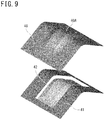
- FIG. 9 illustrates one example of a drawing die for use in the first forming step 9A designed by the above-described method.
- a lower surface (a pressing surface) of a die 40 has a shape bent out of a plane in such a manner as to protrude upward, and is formed with a protrusion shape 40A having a projection shape designed in such a manner as to extend in a direction intersecting with a position of the bending.
- Upper end portions of a punch 42 are set to follow the protrusion shape having the projection shape.
- a blank holder 41 is a component configured to press the flange portion forming positions 14, and is provided with an out-of-plane bending shape that protrudes upward.
- the die 40 and the blank holder 41 pinch the flange portion forming positions 14 of the metal sheet 10 to perform out-of-plane bending on the metal sheet 10.
- the punch 42 is lifted relatively upward to perform drawing of the projection shape on the top sheet portion forming position 12 and the vertical wall portion forming positions 13 of the metal sheet 10, thereby providing the projection portion 30A.
- the intermediate formed-product 30 as illustrated in FIG. 5 is produced as the metal sheet 10 to be press formed in the second forming step 9B.
- the second forming step 9B is a step of performing bending on the intermediate formed product 30 formed in the first forming step 9A to form the ridge lines 6 between the top sheet portion 2 and the vertical wall portions 3 and the ridge lines 7 between the vertical wall portions 3 and the flange portions 4 in the desired press-formed component shape 1, thereby forming the intermediate formed product 30 into the desired press-formed component shape 1.
- the second forming step 9B uses a bending die, for example, as illustrated in FIG. 10 , configured to perform bending of ridge line portion positions and include an upper die formed by a die 50 and bending blades 52 and a lower die formed by a punch 51.
- a bending die for example, as illustrated in FIG. 10 , configured to perform bending of ridge line portion positions and include an upper die formed by a die 50 and bending blades 52 and a lower die formed by a punch 51.
- the top sheet portion forming position 12 of the metal sheet 10 is pinched by the punch 51 and the die 50, and in this state, the bending blades 52 on left and right are moved down to a forming bottom dead center toward the punch 51 to perform bending of the vertical wall portions 3 and the vertical wall portions 3.
- the bending blades 52 are preferably configured to perform the forming by moving at an angle ranging from 0 degrees to 90 degrees, and preferably from 0 degrees to 45 degrees, with respect to a normal angle of pressing, toward a direction away from the punch 51.
- the bending angle ⁇ when bending the flat metal sheet 10 out of the plane in the first forming step 9A was set to 120 degrees, which was smaller than in the final desired press-formed component shape 1.
- a shape (a profile) as a projection shape was designed by setting the height h of the projection vertex P1 illustrated in FIG. 6 to 24 mm, the height h' of the intermediate point P3 illustrated therein to 10 mm, and the end point P2 to end portions of the metal sheet 10 and smoothly connecting them by a spline curve in the order of the intermediate point P3, the projection vertex P1, the intermediate point P3, and the end point P2.
- a drawing analysis was performed by an upper die formed by the die 40 having the shape designed above and a lower die formed by the punch 42 and the blank holder 41 to obtain the intermediate formed product 30.
- a blank holding force of 50 ton was applied.
- the bending blades 52 bending the ridge lines 6, 7 used a cam mechanism for bending at an angle ⁇ inclined by 30 degrees with respect to the pressing direction to perform the forming analysis.
- FIG. 12 illustrates a die used in the bending analysis
- FIG. 13 illustrates a die used in the drawing analysis.
- the bending die included an upper die formed by a die 61 and a pad 62 and a lower die formed by a punch 63.
- the upper die was lowered, and bending was performed while pinching the top sheet portion 2 in the final component shape by the pad 62 and the punch 63. In this case, a pad pressure of 10 ton was applied.
- the drawing die included an upper die formed by a die 71 and a lower die formed by a punch 73 and a blank holder 72.
- the upper die was lowered, and drawing was performed while pinching the vertical wall portions 3 and the flange portions 4 in the final component shape by the die 71 and the blank holder 72.
- the blank holding force was 50 ton.
- the forming analyses were performed under the above conditions to calculate respective sheet thickness reduction rate distributions at forming bottom dead centers in the conventional bending, the conventional drawing, and the forming method based on the present invention.
- Forming by the conventional bending caused too much excess of material on the flange portions 4 of the final component shape, thereby leading to overlapping wrinkles at two places near the curved portion 1A in the longitudinal direction, which resulted in difficulty in forming.
- the flange portions 4 had no wrinkles although the bending was performed finally.
- the present target shape had no cracks in all of the forming methods.
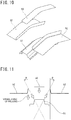
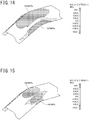
- FIGS. 14 and 15 respectively illustrate a longitudinal sheet thickness center stress distribution at the forming bottom dead center in the conventional drawing and the forming method based on the present invention.
- the component formed by the conventional drawing had a large difference in the longitudinal sheet thickness center stress between the top sheet portion 2 and the flange portions 4, due to which a large spring-back occurred in such a manner that the end portions in the longitudinal direction were lifted up to 3.3 mm on a left side and 2.5 mm on a right side.
- the forming method based on the present invention had almost no difference in the longitudinal sheet thickness center stress between the top sheet portion 2 and the flange faces.
- the method enabled forming to be performed without causing almost any spring-back such as lift of the end portions in the longitudinal direction (in which amounts of lift of both end portions in the longitudinal direction were below 0.9 mm each).
Landscapes
- Engineering & Computer Science (AREA)
- Mechanical Engineering (AREA)
- Shaping Metal By Deep-Drawing, Or The Like (AREA)
- Bending Of Plates, Rods, And Pipes (AREA)
Applications Claiming Priority (2)
| Application Number | Priority Date | Filing Date | Title |
|---|---|---|---|
| JP2018034570 | 2018-02-28 | ||
| PCT/JP2019/006552 WO2019167792A1 (fr) | 2018-02-28 | 2019-02-21 | Procédé de production d'éléments formés à la presse, dispositif de formage à la presse et tôle métallique pour le formage à la presse |
Publications (2)
| Publication Number | Publication Date |
|---|---|
| EP3760331A1 true EP3760331A1 (fr) | 2021-01-06 |
| EP3760331A4 EP3760331A4 (fr) | 2021-04-14 |
Family
ID=67805817
Family Applications (1)
| Application Number | Title | Priority Date | Filing Date |
|---|---|---|---|
| EP19760333.5A Pending EP3760331A4 (fr) | 2018-02-28 | 2019-02-21 | Procédé de production d'éléments formés à la presse, dispositif de formage à la presse et tôle métallique pour le formage à la presse |
Country Status (7)
| Country | Link |
|---|---|
| US (1) | US11628486B2 (fr) |
| EP (1) | EP3760331A4 (fr) |
| JP (1) | JP6631759B1 (fr) |
| KR (1) | KR102361285B1 (fr) |
| CN (1) | CN111727089B (fr) |
| MX (1) | MX2020008953A (fr) |
| WO (1) | WO2019167792A1 (fr) |
Cited By (1)
| Publication number | Priority date | Publication date | Assignee | Title |
|---|---|---|---|---|
| EP3960321A4 (fr) * | 2019-04-22 | 2022-05-11 | JFE Steel Corporation | Procédé de moulage à la presse |
Families Citing this family (7)
| Publication number | Priority date | Publication date | Assignee | Title |
|---|---|---|---|---|
| US12194523B2 (en) | 2020-03-09 | 2025-01-14 | Jfe Steel Corporation | Method for manufacturing pressed component, metal sheet for press forming, and high-tensile steel sheet |
| JP7283439B2 (ja) * | 2020-05-08 | 2023-05-30 | Jfeスチール株式会社 | プレス部品の製造方法、及び金属板 |
| US12030101B2 (en) | 2021-08-12 | 2024-07-09 | Microsoft Technology Licensing, Llc | Variable thickness extruded mobile device enclosure covers |
| CN113414263B (zh) * | 2021-08-23 | 2021-11-19 | 江苏德励达新材料股份有限公司 | 一种板材折弯系统及板材折弯方法 |
| KR20250111498A (ko) | 2024-01-15 | 2025-07-22 | 주식회사 무아정밀 | 금속판재 성형장치 및 성형방법 |
| WO2026028776A1 (fr) * | 2024-07-29 | 2026-02-05 | Jfeスチール株式会社 | Procédé de fabrication pour article moulé à la presse |
| CN119259790B (zh) * | 2024-12-05 | 2025-03-04 | 湖南高创翔宇科技有限公司 | 一种变曲率薄壁微通道结构制造工艺 |
Family Cites Families (16)
| Publication number | Priority date | Publication date | Assignee | Title |
|---|---|---|---|---|
| JPS5353329Y2 (fr) | 1972-02-08 | 1978-12-20 | ||
| JPS51119537A (en) | 1975-04-11 | 1976-10-20 | Matsushita Electric Ind Co Ltd | Water controller |
| JP4090028B2 (ja) * | 2002-11-26 | 2008-05-28 | 日新製鋼株式会社 | 薄鋼板のプレス成形用金型装置 |
| JP4709659B2 (ja) | 2006-02-23 | 2011-06-22 | 新日本製鐵株式会社 | 形状凍結性に優れる多段プレス成形方法 |
| JP5353329B2 (ja) | 2009-03-12 | 2013-11-27 | 日産自動車株式会社 | 形状凍結性に優れたプレス成形方法とプレス成形装置並びに同プレス成形装置の製造方法 |
| JP5794025B2 (ja) * | 2011-07-29 | 2015-10-14 | Jfeスチール株式会社 | 金型設計方法及びプレス成形方法 |
| JP5733475B2 (ja) * | 2012-09-12 | 2015-06-10 | 新日鐵住金株式会社 | 湾曲部品の製造方法及び湾曲部品の製造装置 |
| CN104903020B (zh) * | 2013-01-07 | 2016-12-21 | 新日铁住金株式会社 | 冲压成型品的制造方法 |
| JP5649696B1 (ja) | 2013-07-12 | 2015-01-07 | 三菱電機株式会社 | エネルギーマネジメントシステム、端末装置、端末装置の制御方法、及び、プログラム |
| KR101869177B1 (ko) * | 2013-12-26 | 2018-06-19 | 신닛테츠스미킨 카부시키카이샤 | 모자형 단면 부품의 제조 방법 |
| CA2966971A1 (fr) * | 2014-11-12 | 2016-05-19 | Nippon Steel & Sumitomo Metal Corporation | Procede de fabrication et dispositif de fabrication d'un article moule par compression |
| RU2669956C1 (ru) * | 2014-12-22 | 2018-10-17 | Ниппон Стил Энд Сумитомо Метал Корпорейшн | Способ изготовления компонента с поперечным сечением в форме шляпы |
| MX369681B (es) | 2016-03-01 | 2019-11-15 | Jfe Steel Corp | Método para la fabricación de producto moldeado por prensado. |
| JP6504130B2 (ja) | 2016-08-03 | 2019-04-24 | Jfeスチール株式会社 | プレス成形品の製造方法 |
| WO2018030240A1 (fr) * | 2016-08-09 | 2018-02-15 | Jfeスチール株式会社 | Procédé de fabrication d'article formé à la presse |
| JP6633478B2 (ja) | 2016-08-30 | 2020-01-22 | 株式会社日立製作所 | 信号保安システムおよび信号保安方法 |
-
2019
- 2019-02-21 JP JP2019536617A patent/JP6631759B1/ja active Active
- 2019-02-21 MX MX2020008953A patent/MX2020008953A/es unknown
- 2019-02-21 CN CN201980013263.7A patent/CN111727089B/zh active Active
- 2019-02-21 KR KR1020207024098A patent/KR102361285B1/ko active Active
- 2019-02-21 US US16/970,579 patent/US11628486B2/en active Active
- 2019-02-21 EP EP19760333.5A patent/EP3760331A4/fr active Pending
- 2019-02-21 WO PCT/JP2019/006552 patent/WO2019167792A1/fr not_active Ceased
Cited By (2)
| Publication number | Priority date | Publication date | Assignee | Title |
|---|---|---|---|---|
| EP3960321A4 (fr) * | 2019-04-22 | 2022-05-11 | JFE Steel Corporation | Procédé de moulage à la presse |
| US12109600B2 (en) | 2019-04-22 | 2024-10-08 | Jfe Steel Corporation | Press forming method |
Also Published As
| Publication number | Publication date |
|---|---|
| EP3760331A4 (fr) | 2021-04-14 |
| MX2020008953A (es) | 2020-10-15 |
| JP6631759B1 (ja) | 2020-01-15 |
| US11628486B2 (en) | 2023-04-18 |
| CN111727089B (zh) | 2022-06-14 |
| KR20200106974A (ko) | 2020-09-15 |
| KR102361285B1 (ko) | 2022-02-09 |
| CN111727089A (zh) | 2020-09-29 |
| US20210114076A1 (en) | 2021-04-22 |
| WO2019167792A1 (fr) | 2019-09-06 |
| JPWO2019167792A1 (ja) | 2020-04-16 |
Similar Documents
| Publication | Publication Date | Title |
|---|---|---|
| EP3760331A1 (fr) | Procédé de production d'éléments formés à la presse, dispositif de formage à la presse et tôle métallique pour le formage à la presse | |
| EP3760332B1 (fr) | Procédé de production d'éléments pressés, dispositif de moulage à la presse et plaque métallique pour moulage à la presse | |
| EP3760330B1 (fr) | Plaque métallique pour moulage à la presse, dispositif de moulage à la presse et procédé de production pour un élément pressé | |
| EP3501684B1 (fr) | Composant formé à la presse de carrosserie automobile et son procédé de fabrication | |
| EP2471610A1 (fr) | Procédé de formation à la presse | |
| EP3272438B1 (fr) | Procédé permettant de produire un produit moulé à la presse, produit moulé à la presse et dispositif de pressage | |
| KR20160145130A (ko) | 블랭크 및 프레스 성형품의 제조 방법 | |
| KR102291185B1 (ko) | 프레스 성형품의 제조 방법 | |
| KR102609315B1 (ko) | 프레스 성형 방법 | |
| US11951526B2 (en) | Press-formed product manufacturing method and forming die | |
| TW201707809A (zh) | 沖壓零件之製造方法及製造裝置 | |
| KR20170010832A (ko) | 프레스 성형품의 제조 방법 및 프레스 금형 | |
| CN108698104B (zh) | 冲压成型品的制造方法 | |
| US11260443B2 (en) | Method for manufacturing press formed product | |
| KR102023541B1 (ko) | 신장 플랜지 성형 부품의 제조 방법 | |
| CN115666809A (zh) | 冲压成形方法 | |
| JP2022080353A (ja) | プレス成形方法及びプレス成形金型 | |
| EP4137245B1 (fr) | Moule de formage sous pression et procédé de formage sous pression | |
| CN105848801A (zh) | 冲压成型方法以及冲压成型部件的制造方法 | |
| JP7111057B2 (ja) | プレス成形方法 | |
| EP3778053A1 (fr) | Procédé de conception pour article moulé à la presse, matrice de moulage à la presse, article moulé à la presse et procédé de production d'article moulé à la presse | |
| JP7205520B2 (ja) | プレス部品の製造方法及びプレス成形用の金属板 | |
| EP4578566A1 (fr) | Procédé de fabrication et flan pour produit formé à la presse | |
| KR20250111186A (ko) | 프레스 성형품의 제조 방법 |
Legal Events
| Date | Code | Title | Description |
|---|---|---|---|
| STAA | Information on the status of an ep patent application or granted ep patent |
Free format text: STATUS: THE INTERNATIONAL PUBLICATION HAS BEEN MADE |
|
| PUAI | Public reference made under article 153(3) epc to a published international application that has entered the european phase |
Free format text: ORIGINAL CODE: 0009012 |
|
| STAA | Information on the status of an ep patent application or granted ep patent |
Free format text: STATUS: REQUEST FOR EXAMINATION WAS MADE |
|
| 17P | Request for examination filed |
Effective date: 20200825 |
|
| AK | Designated contracting states |
Kind code of ref document: A1 Designated state(s): AL AT BE BG CH CY CZ DE DK EE ES FI FR GB GR HR HU IE IS IT LI LT LU LV MC MK MT NL NO PL PT RO RS SE SI SK SM TR |
|
| AX | Request for extension of the european patent |
Extension state: BA ME |
|
| REG | Reference to a national code |
Ref country code: DE Ref legal event code: R079 Free format text: PREVIOUS MAIN CLASS: B21D0022260000 Ipc: B21D0019080000 |
|
| A4 | Supplementary search report drawn up and despatched |
Effective date: 20210316 |
|
| RIC1 | Information provided on ipc code assigned before grant |
Ipc: B21D 19/08 20060101AFI20210310BHEP Ipc: B21D 22/02 20060101ALI20210310BHEP Ipc: B21D 22/20 20060101ALI20210310BHEP Ipc: B21D 53/88 20060101ALI20210310BHEP Ipc: B21D 25/00 20060101ALN20210310BHEP |
|
| DAV | Request for validation of the european patent (deleted) | ||
| DAX | Request for extension of the european patent (deleted) | ||
| STAA | Information on the status of an ep patent application or granted ep patent |
Free format text: STATUS: EXAMINATION IS IN PROGRESS |
|
| 17Q | First examination report despatched |
Effective date: 20231025 |
|
| GRAP | Despatch of communication of intention to grant a patent |
Free format text: ORIGINAL CODE: EPIDOSNIGR1 |
|
| STAA | Information on the status of an ep patent application or granted ep patent |
Free format text: STATUS: GRANT OF PATENT IS INTENDED |
|
| RIC1 | Information provided on ipc code assigned before grant |
Ipc: B21D 19/08 20060101AFI20260128BHEP Ipc: B21D 22/02 20060101ALI20260128BHEP Ipc: B21D 22/20 20060101ALI20260128BHEP Ipc: B21D 53/88 20060101ALI20260128BHEP Ipc: B21D 25/00 20060101ALN20260128BHEP |
|
| INTG | Intention to grant announced |
Effective date: 20260210 |
|
| GRAJ | Information related to disapproval of communication of intention to grant by the applicant or resumption of examination proceedings by the epo deleted |
Free format text: ORIGINAL CODE: EPIDOSDIGR1 |
|
| STAA | Information on the status of an ep patent application or granted ep patent |
Free format text: STATUS: EXAMINATION IS IN PROGRESS |