EP3760508A1 - Appareil télescopique de coupleur et coupleur - Google Patents
Appareil télescopique de coupleur et coupleur Download PDFInfo
- Publication number
- EP3760508A1 EP3760508A1 EP18880619.4A EP18880619A EP3760508A1 EP 3760508 A1 EP3760508 A1 EP 3760508A1 EP 18880619 A EP18880619 A EP 18880619A EP 3760508 A1 EP3760508 A1 EP 3760508A1
- Authority
- EP
- European Patent Office
- Prior art keywords
- drawbar
- housing
- coupler
- hole
- locking ring
- Prior art date
- Legal status (The legal status is an assumption and is not a legal conclusion. Google has not performed a legal analysis and makes no representation as to the accuracy of the status listed.)
- Granted
Links
Images

Classifications
-
- B—PERFORMING OPERATIONS; TRANSPORTING
- B61—RAILWAYS
- B61G—COUPLINGS; DRAUGHT AND BUFFING APPLIANCES
- B61G9/00—Draw-gear
- B61G9/20—Details; Accessories
-
- B—PERFORMING OPERATIONS; TRANSPORTING
- B61—RAILWAYS
- B61G—COUPLINGS; DRAUGHT AND BUFFING APPLIANCES
- B61G9/00—Draw-gear
- B61G9/04—Draw-gear combined with buffing appliances
Definitions
- the present application belongs to the technical field of railway vehicles coupling, and particularly relates to a coupler telescopic apparatus and a coupler.
- a telescopic apparatus can ensure smooth completion of two actions (i.e., extending and retracting the coupler) during train operation.
- the telescopic apparatus is required to have a reasonable locking mechanism.
- Existing automatic coupler telescopic apparatus for couplers is mainly locked by the following: (1) latch, which are simple in structure but small in pressure-receiving cross-sectional area; (2) block, which are relatively simple in structure, but are easy to wear and deform at contact surfaces for a long time since the contact surfaces are two curved surfaces with different radii; and, (3) spline.
- Chinese Invention Patent CN102424057A has disclosed a telescopic mechanism of a telescopic coupler buffer apparatus for a high-speed Electric Multiple Units, comprising: a pressure-receiving rod that is positioned inside a movable housing of the coupler buffer apparatus with one end connected to the movable housing, and a load-bearing joint that is sleeved on the pressure-receiving rod, wherein a guide drum is fixedly mounted outside the load-bearing joint; a telescopic diving mechanism is arranged between the guide drum and the movable housing; the end of the pressure-receiving rod is connected to the movable housing through a torsion spring, and the pressure-receiving rod and the load-bearing joint are kept in a locked state; a locking mechanism comprises bumps that are positioned at the other end of the pressure-receiving rod and distributed at intervals and grooves that are formed on an inner wall of the load-bearing joint and fitted with the bump
- the telescopic driving mechanism due to a presence of the pressure-receiving rod, the telescopic driving mechanism can only be arranged outside the housing, resulting in defects of large space occupation and complex structure.
- the present application provides a coupler telescopic apparatus which can reduce space occupation and have simple structure, and also provides a coupler using the coupler telescopic apparatus.
- a coupler telescopic apparatus comprising a housing and a drawbar capable of extending and retracting along the housing, the housing is sleeved outside the drawbar, a limiting block is fixed arranged on an outer side face of the drawbar, a locking ring capable of coming into contact with the limiting block is sleeved inside the housing, and the locking ring is coaxial with the housing and rotatably connected to the housing; a through groove is axially formed on an inner surface of the locking ring, and the through groove correspond to the limiting block in shape, so that the limiting block passes through the through groove when the through groove is aligned with the limiting block, and then an extension of the drawbar is locked by rotating the locking ring to block the limiting block after the extension of the drawbar is completed.
- the plurality of limiting blocks are arranged at intervals about an axis of the drawbar, and there are a plurality of through grooves corresponding to the limiting blocks.
- a telescopic cylinder is arranged in the housing, and two ends of the telescopic cylinder are connected to the housing and the drawbar, respectively, to drive the drawbar to extend or retract along the housing.
- the drawbar is sleeve-shaped, and the drawbar is sleeved outside the telescopic cylinder; a body of the telescopic cylinder is connected to the housing; the drawbar has an extension end capable of extending out from the housing, and a rod of the telescopic cylinder is connected to the extension end of the drawbar.
- a first hole is formed on a side of the housing, and a locking pin is sleeved inside the first hole; a second hole is formed on an outer side face of the drawbar; and, the second hole corresponds to the first hole, so that the second hole is aligned with the first hole and the locking pin extends into the second hole after the drawbar is retracted, so as to lock a retraction of the drawbar.
- the coupler telescopic apparatus further comprises a linkage assembly, the linkage assembly is connected to the locking pin to drive the locking pin to do a reciprocating motion of extending into or out from the second hole; the linkage assembly is connected to the locking ring, so as to drive the locking ring to rotate until blocking the limiting block when the locking pin extends into the second hole, and to drive the locking ring to rotate until the through groove is aligned with the limiting block when the locking pin extends out from the second hole.
- the linkage assembly comprises a rotating arm, a pulley block, a pull rope and an elastic member;
- the rotating arm is rotatably connected to an outer wall of the housing, and the rotating arm is connected to the locking pin to drive the locking pin to do the reciprocating motion of extending into or out from the second hole by rotating;
- the pulley block is fixedly arranged on the outer wall of the housing; one end of the pull rope is connected to the rotating arm, while an other end of the pull rope goes around the pulley block and is connected to the elastic member;
- the locking ring is fixedly connected to the pull rope to synchronously rotate with the rotating arm under a drive of the pull rope; and, the elastic member is fixedly connected to the housing to extend or contract along with a movement of the pull rope.
- an unlocking cylinder is fixedly arranged on the outer wall of the housing, and the unlocking cylinder is connected to the rotating arm to drive the rotating arm to rotate.
- an unlocking handle is fixedly connected to the rotating arm to drive the rotating arm to rotate.
- a coupler comprising a telescopic apparatus, and the telescopic apparatus is the coupler telescopic apparatus described above.
- the present application has the following advantages and positive effects.
- the fixed connection in the present application may be detachable fixed connection or integral fixed connection;
- the orientation or position relation indicated by terms “inner”, “outer”, “upper”, “lower”, “front”, “rear” or the like is an orientation or position relation shown by the accompanying drawings, merely for describing the present application and simplifying the description rather than indicating or implying that the specified apparatus or element must have a particular orientation or be constructed and operated in a particular orientation, so the terms should not be interpreted as limitations to the present application; and
- the terms “first” and “second” are merely descriptive, and cannot be interpreted as indicating or implying the relative importance.
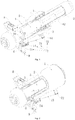
- a coupler telescopic apparatus provided by an embodiment of the present application comprises a housing 1 and a drawbar 2 capable of extending and retracting along the housing 1; the housing 1 is sleeved outside the drawbar 2, and the drawbar 2 is coaxial with the housing 1, the drawbar 2 is in sliding fit with the housing 1 to extend or retract along the housing 1.
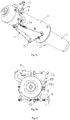
- Figs. 1-3 are structure diagrams of the coupler telescopic apparatus according to the embodiment of the present application, where Fig. 1 is a schematic diagram under a state that the drawbar 2 is extended, and Fig. 2 is a schematic diagram under a state that the drawbar 2 is retracted. In Figs. 1 and 2 , a portion of the housing 1 and a portion of the drawbar 2 are removed to clearly show fitting relationships between internal components.
- Fig. 3 is an external structure diagram
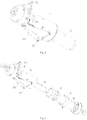
- Fig. 4 is an exploded view of the coupler telescopic apparatus.
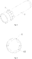
- Fig. 5 shows a structure of the drawbar 2 according to the embodiment of the present application.
- a limiting block 3 is fixedly arranged on an outer side face of the drawbar 2, and a locking ring 4 capable of coming into contact with the limiting block 3 is sleeved inside the housing 1.
- the locking ring 4 is coaxial with the housing 1 and rotatably connected to the housing 1.
- a structure of the locking ring is shown in Fig. 5 .
- a through groove 41 is axially formed on an inner surface of the locking ring 4, and the through groove 41 correspond to the limiting block 3 in shape, e.g., the through groove 41 and the limiting block 3 may be connected in a key-groove fitting manner, so that the limiting block 3 passes through the through groove 41 when the through groove 41 is aligned with the limiting block 3, and then an extension of the drawbar 2 is locked by rotating the locking ring 4 to block the limiting block 3 after the extension of the drawbar is completed.
- a fitting mode of the limiting block 3 and the locking ring 4 is shown in Fig. 7 .
- the limiting block 3 are aligned with the through groove 41 on the locking ring 4, the drawbar 2 extends out (moving away from the locking ring 4), and the limiting block 3 passes through the through groove 41.
- the locking ring 4 is rotated to misalign the through groove 41 with the limiting block 3, so as to limit the movement of the limiting block 3 toward the locking ring 4 and thus lock the extension of the drawbar 2.
- the locking ring 4 is rotated to align the limiting block 3 with the through groove 41, so that the drawbar 2 can be retracted into the housing 1 after passing through the through groove 41.
- the coupler telescopic apparatus provided by the present application, by fixedly arranging limiting block 3 outside the drawbar 2 and rotatably arranging a locking ring 4 in the housing 1, when the drawbar 2 extends out from the housing 1, the drawbar 2 can be locked by only rotating the locking ring 4. Therefore, compared with the existing telescopic mechanisms, the internal structure of the housing 1 is simplified, the space inside the housing 1 is saved, and it is advantageous to arrange external driving structures in the housing 1 and reduce space occupation.
- a plurality of limiting blocks 3 that are arranged at intervals about an axis of the drawbar 2.
- the limiting blocks 3 are arranged about the axis of the drawbar 2 in a circular array.
- a telescopic cylinder 5 is arranged in the housing 1, and two ends of the telescopic cylinder 5 are connected to the housing 1 and the drawbar 2, respectively, to drive the drawbar 2 to extend or retract along the housing 1.
- the drawbar 2 is sleeve-shaped, so that the drawbar 2 is sleeved outside the telescopic cylinder 5 when the drawbar 2 is retracted, with reference to Fig. 2 .
- a body 51 of the telescopic cylinder 5 is connected to the housing 1, the drawbar 2 has an extension end capable of extending out from the housing 1, and a rod 52 of the telescopic cylinder 5 is connected to the extension end of the drawbar 2 so as to control the extension or retraction of the drawbar 2.
- the body 51 of the telescopic cylinder 5 is coaxial with the housing 1, and the body 51 of the telescopic cylinder 5 is connected to the housing 1 through a spherical plain bearing.
- the rod 52 of the telescopic cylinder 5 is connected to the drawbar 2 through a spherical plain bearing, so that the telescopic cylinder 5 has a freedom of rotation, thus avoiding a damage to the telescopic cylinder 5 caused by a bending moment during extension.
- a first hole 11 is formed on a side of the housing 1, and a locking pin 6 is sleeved inside the first hole 11; a second hole 21 is formed on an outer side face of the drawbar 2; and, the second hole 21 corresponds to the first hole 11, so that the second hole is aligned with the first hole and the locking pin 6 extends into the second hole after the drawbar is retracted, so as to lock a retraction of the drawbar 2, as shown in Fig. 2 .
- the drawbar 2 in a retracted or extended state can be locked by the locking pin 6 and the locking ring 4, respectively.
- the locking ring 4 and the drawbar 2 form a spline-type locking mechanism used for bearing a larger force during extension locking
- the locking pin 6 and the drawbar 2 form a latch-type locking mechanism which is simple in structure and used for bearing a smaller force during retraction locking. Therefore, with the coupler telescopic apparatus provided by the present application, the structure is further simplified, and the efficiency of expanding or retracting couplers is improved.
- the coupler telescopic apparatus further comprises a linkage assembly 7, the linkage assembly 7 is connected to the locking pin 6 to drive the locking pin 6 to do a reciprocating motion of extending into or out from the second hole; the linkage assembly 7 is connected to the locking ring 4, so as to drive the locking ring 4 to rotate until blocking the limiting blocks 3 when the locking pin 6 extends into the second hole, and to drive the locking ring 4 to rotate until the through grooves are aligned with the limiting blocks 3 when the locking pin 6 extends out from the second hole.
- the locking pin 6 and the locking ring 4 can be synchronously driven to move.
- a number of driving elements is decreased, and the structure is further simplified; on the other hand, a control to the movements of the locking pin 6 and the locking ring 4 is simplified, and the efficiency of extending or retracting couplers is further improved.
- a structure of the linkage assembly 7 may be as following. As shown in Figs. 1-3 , the linkage assembly 7 comprises a rotating arm 71, a pulley block 72, a pull rope 73 and an elastic member 74, the rotating arm 71 is rotatably connected to an outer wall of the housing 1, and the rotating arm 71 is connected to the locking pin 6 to drive the locking pin 6 to do the reciprocating motion of extending into or out from the second hole 21 by rotating; the pulley block 72 is fixedly arranged on the outer wall of the housing 1, one end of the pull rope 73 is connected to the rotating arm 71, while an other end of the pull rope 73 goes around the pulley block and is connected to the elastic member 74; the locking ring 4 is fixedly connected to the pull rope 73 to synchronously rotate with the rotating arm 71 under a drive of the pull rope 73; the elastic member 74 is fixedly connected to the housing 1 to extend or contract along with the movement of the pull rope 73.
- the rotating arm 71 is preferably a lever, and a hinge block 10 is hinged at a pivot point of the rotating arm 71, and the hinge block 10 is fixedly connected to the outer wall of the housing 1, one end of the rotating arm 71 is connected to an unlocking cylinder 8 to automatically drive the rotating arm 71 to rotate.
- the unlocking cylinder 8 is arranged on the outer wall of the housing 1, a body of the unlocking cylinder 8 is hinged to the housing 1, and a rod of the unlocking cylinder 8 is hinged to the rotating arm 71, and an other end of the rotating arm 71 is fixedly connected to the pull rope 73 and an unlocking handle 9.
- the unlocking handle 9 is used to drive the rotating arm 71 to rotate in a manual driving manner when the unlocking cylinder 8 does not operate.
- a long through hole 711 is formed on a side of the pivot point of the rotating arm 71 (at a position where the rotating arm 71 is hinged to the locking pin 6) in a length direction of the rotating arm 71.
- the locking pin 6 has a rotating shaft, and the rotating shaft of the locking pin 6 is sleeved inside the long through hole 711 of the rotating arm 71 to do a reciprocating motion along the long through hole of the rotating arm 71 during its rotation relative to the rotating arm 71.
- the pulley block 72 comprises three pulleys, and the three pulleys are arranged in a triangle shape, one pulley is located on a side of the rotating arm 71, and the other two pulleys are located at a side of the locking rind 4; the pull rope 73 successively goes around the three pulleys from the rotating arm 71 to be fixedly connected to the elastic member 74.
- the elastic member 74 is preferably a telescopic spring, and two ends of the elastic member 74 are fixedly connected to the pull rope 73 and the housing 1, respectively.
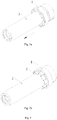
- Fig. 8 is a schematic structure diagram of the linkage assembly 7 in a locked state, where Fig. 8a is a stereoscopic view, and Fig. 8b is a left view of Fig. 8a .
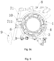
- Fig. 9 is a schematic structure diagram of the linkage assembly 7 in an unlocked state, where Fig. 9a is a stereoscopic view, Fig. 9b is a left view of Fig. 9a , and Fig. 9c is a sectional view along A-A.
- a chute 12 is formed on the outer wall of the housing 1 corresponding to the locking ring 4, the chute 12 runs through the housing 1 in a thickness direction of the housing 1, and the chute is arc-shaped; the locking ring 4 is fixedly connected to a synchronous element 42, and the synchronous element 42 is in sliding fit with the chute 12 to do a reciprocating motion along the chute 12; the synchronous element 42 is fixedly connected to the pull rope 73 to transfer a reciprocating motion of the pull rope 73 to the locking ring 4, so as to realize a reciprocating motion of the locking ring 4.
- the drawbar 2 is completely retracted.
- the locking pin 6 is at a locking position and forms the latch-type locking with the drawbar 2.
- the state of the linkage assembly 7 is shown in Fig. 8 (however, it differs from Fig. 8 that the drawbar 2 is in a retracted state at this time).
- the rotating arm 71 By retracting of the unlocking cylinder 8 or pulling the unlocking handle 9, the rotating arm 71 is driven to rotate to pull the locking pin 6 out from the drawbar 2. At this time, the state of the linkage assembly 7 changes from Fig. 8 to Fig. 9 (however, it differs from Fig. 9 that the drawbar 2 has not yet extended at this time). Meanwhile, the rotating arm 71 pulls the pull rope 73, so that the synchronous element 42 moves from one side to the other side of the chute 12, and the synchronous element 42 drives the locking ring 4 to rotate to align the limiting blocks 3 with the through grooves 41. At this time, both the locking ring 4 and the locking pin 6 reach the unlocking position.
- the telescopic cylinder 5 extends out to drive the drawbar 2 to extend out.
- the limiting blocks 3 smoothly pass through the through grooves 41 (with reference to Fig. 7 ).
- the unlocking cylinder 8 is reset or the unlocking handle 9 is released.
- the elastic member 74 By the function of the elastic member 74, the locking ring 4 and the locking pin 6 are restored to the locking position, that is, the linkage assembly 7 is restored to the state shown in Fig. 8 .
- the limiting blocks 3 are misaligned with the through grooves on the locking ring 4, and the drawbar 2 cannot be retracted, so that the extension locking is realized.
- the state of the coupler telescopic apparatus is shown in Fig. 1 .
- the drawbar 2 is completely extended.
- the locking pin 6 is at the locking position and forms the spline-type locking with the drawbar 2.
- the state of the linkage assembly 7 is shown in Fig. 8 .
- the rotating arm 71 By retracting of the unlocking cylinder 8 or pulling the unlocking handle 9, the rotating arm 71 is driven to rotate to pull the locking pin 6 out from the drawbar 2. At this time, the state of the linkage assembly 7 changes from Fig. 8 to Fig. 9 . Meanwhile, the rotating arm 71 pulls the pull rope 73, so that the synchronous element 42 moves from one side to the other side of the chute 12, and the synchronous element 42 drives the locking ring 4 to rotate to align the limiting blocks 3 with the through grooves 41. At this time, both the locking ring 4 and the locking pin 6 reach the unlocking position.
- the telescopic cylinder 5 is retracted to drive the drawbar 2 to retract. During this process, the limiting blocks 3 smoothly pass through the through grooves 41.
- the unlocking cylinder 8 is reset or the unlocking handle 9 is released.
- the locking ring 4 and the locking pin 6 are restored to the locking position, that is, the linkage assembly 7 is restored to the state shown in Fig. 8 (however, it differs from Fig. 8 that the drawbar 2 is in the retracted state at this time).
- the locking pin 6 forms the latch-type locking with the drawbar 2 again, and the drawbar 2 cannot extend out, so that the retraction locking is realized.
- the state of the coupler telescopic apparatus is shown in Fig. 2 .
- Another embodiment of the present application further provides a coupler, comprising a telescopic apparatus.
- a specific structure of the telescopic apparatus refers to the above embodiment. Since the coupler employs all the technical solutions in the above embodiment, the coupler at least achieves all beneficial effects brought by the technical solutions in the above embodiment, and it will not be repeated here.
Landscapes
- Engineering & Computer Science (AREA)
- Mechanical Engineering (AREA)
- Mutual Connection Of Rods And Tubes (AREA)
Applications Claiming Priority (2)
| Application Number | Priority Date | Filing Date | Title |
|---|---|---|---|
| CN201810677483.7A CN108839668B (zh) | 2018-06-27 | 2018-06-27 | 车钩伸缩装置及车钩 |
| PCT/CN2018/118557 WO2019101218A1 (fr) | 2018-06-27 | 2018-11-30 | Appareil télescopique de coupleur et coupleur |
Publications (3)
| Publication Number | Publication Date |
|---|---|
| EP3760508A1 true EP3760508A1 (fr) | 2021-01-06 |
| EP3760508A4 EP3760508A4 (fr) | 2021-05-19 |
| EP3760508B1 EP3760508B1 (fr) | 2022-04-20 |
Family
ID=64202366
Family Applications (1)
| Application Number | Title | Priority Date | Filing Date |
|---|---|---|---|
| EP18880619.4A Active EP3760508B1 (fr) | 2018-06-27 | 2018-11-30 | Appareil télescopique de coupleur et coupleur |
Country Status (7)
| Country | Link |
|---|---|
| US (1) | US11014584B2 (fr) |
| EP (1) | EP3760508B1 (fr) |
| JP (1) | JP6964802B2 (fr) |
| CN (1) | CN108839668B (fr) |
| ES (1) | ES2912532T3 (fr) |
| RU (1) | RU2747675C1 (fr) |
| WO (1) | WO2019101218A1 (fr) |
Families Citing this family (11)
| Publication number | Priority date | Publication date | Assignee | Title |
|---|---|---|---|---|
| CN108839668B (zh) | 2018-06-27 | 2020-01-31 | 中车青岛四方车辆研究所有限公司 | 车钩伸缩装置及车钩 |
| US11613935B2 (en) * | 2019-10-17 | 2023-03-28 | Vermeer Manufacturing Company | Couplers for connecting a power source to a drilling string |
| CN110615014B (zh) * | 2019-10-28 | 2024-11-01 | 中车南京浦镇车辆有限公司 | 轨道车辆折叠车钩固定装置 |
| CN111907497B (zh) * | 2020-08-14 | 2022-11-18 | 中车齐齐哈尔车辆有限公司 | 一种集成制动装置及具有其的铁路货车 |
| CN112706796B (zh) * | 2021-01-11 | 2024-06-04 | 中车青岛四方车辆研究所有限公司 | 一种车钩用伸缩式导引装置 |
| CN115848430B (zh) * | 2021-09-23 | 2024-10-29 | 比亚迪股份有限公司 | 车钩伸缩装置和车钩 |
| CN114802336B (zh) * | 2022-05-31 | 2024-01-30 | 中车制动系统有限公司 | 伸缩车钩锁定装置 |
| CN114889666B (zh) * | 2022-06-28 | 2024-05-03 | 中车制动系统有限公司 | 电动解钩机构 |
| CN115886901B (zh) * | 2022-10-28 | 2025-06-13 | 山东冠龙医疗用品有限公司 | 一种神经牵引保护装置 |
| CN116851387B (zh) * | 2023-02-03 | 2025-12-23 | 楚天科技股份有限公司 | 一种洗瓶机的转盘结构 |
| WO2025055058A1 (fr) * | 2023-09-12 | 2025-03-20 | 中车制动系统有限公司 | Ensemble attelage à charnière à deux sections et véhicule ferroviaire le comprenant |
Family Cites Families (26)
| Publication number | Priority date | Publication date | Assignee | Title |
|---|---|---|---|---|
| DE1131721B (de) * | 1960-12-02 | 1962-06-20 | Knorr Bremse Kg | Gefederte Stossvorrichtung fuer Schienenfahrzeuge |
| US3326573A (en) * | 1965-07-30 | 1967-06-20 | Jr Maurice Joseph Neitzey | Draft device or trailer hitch |
| US3776579A (en) * | 1971-03-11 | 1973-12-04 | Stanley Aviation Corp | Coupling assemblies |
| DD107878A1 (fr) * | 1973-10-26 | 1974-08-20 | ||
| US4175667A (en) * | 1976-10-15 | 1979-11-27 | Miner Enterprises, Inc. | Method of preshortening draft gear |
| FR2570654B1 (fr) * | 1984-09-24 | 1987-01-02 | Jeanson Rene | Dispositif d'attelage extensible pour vehicules routiers et ferroviaires |
| US5465944A (en) * | 1991-12-13 | 1995-11-14 | Oleo International Holdings Limited | Buffer |
| JP2967000B2 (ja) * | 1992-03-30 | 1999-10-25 | 株式会社ナブコ | 車両用連結装置の伸縮装置 |
| US5826735A (en) * | 1996-08-05 | 1998-10-27 | Emerald Rail Technologies, Llc | Railcar cushion device valving systems |
| US5871109A (en) * | 1996-08-05 | 1999-02-16 | Emerald Rail Technologies, Llc | Railcar cushion device preload valving systems |
| US20040201200A1 (en) * | 2003-04-14 | 2004-10-14 | Don Ahlquist | Can hitch |
| US7150368B2 (en) * | 2003-09-16 | 2006-12-19 | Sharma & Associates, Inc. | Cushioning device having an electrically actuated lockout |
| CN200992120Y (zh) * | 2006-12-21 | 2007-12-19 | 东风扬子江汽车(武汉)有限责任公司 | 伸缩式拖车钩 |
| PT1955918E (pt) * | 2007-02-08 | 2009-07-16 | Voith Patent Gmbh | Engate central automático de amortecimento |
| ES2380106T3 (es) * | 2009-10-01 | 2012-05-08 | Voith Patent Gmbh | Dispositivo para amortiguar fuerzas de tracción y compresión |
| CN202368279U (zh) * | 2011-11-14 | 2012-08-08 | 北汽福田汽车股份有限公司 | 伸缩式拖车钩装置和包括该拖车钩装置的汽车 |
| CN102424057B (zh) * | 2011-12-05 | 2015-04-15 | 青岛四方车辆研究所有限公司 | 高速动车组用伸缩式钩缓装置伸缩机构 |
| RU2581409C1 (ru) * | 2012-03-13 | 2016-04-20 | СиАрАрСи ЦИНДАО СЫФАН РОЛЛИНГ СТОК РИСЕРЧ ИНСТИТЬЮТ КО., ЛТД. | Телескопический механизм в телескопическом прицепном буферном устройстве для использования в высокоскоростных электрических мотор-вагонных составах |
| JP6121871B2 (ja) * | 2013-10-23 | 2017-04-26 | 株式会社日立産機システム | 自動搬送装置 |
| CN106218662B (zh) * | 2016-08-23 | 2018-07-10 | 中车青岛四方车辆研究所有限公司 | 伸缩式车钩缓冲装置 |
| CN106515783B (zh) * | 2016-11-14 | 2018-06-01 | 中车青岛四方车辆研究所有限公司 | 具有防转结构的螺纹接口缓冲器 |
| CN106809240B (zh) * | 2016-12-29 | 2017-12-12 | 比亚迪股份有限公司 | 车钩和具有车钩的有轨列车 |
| RU173118U1 (ru) * | 2017-04-06 | 2017-08-14 | Валентин Карпович Милованов | Тяговый узел подвижного состава |
| RU176272U1 (ru) * | 2017-04-06 | 2018-01-15 | Валентин Карпович Милованов | Устройство поглощения энергии |
| CN207038431U (zh) * | 2017-07-31 | 2018-02-23 | 衢州市金鹏电器有限公司 | 一种远距离手动操作真空断路器 |
| CN108839668B (zh) * | 2018-06-27 | 2020-01-31 | 中车青岛四方车辆研究所有限公司 | 车钩伸缩装置及车钩 |
-
2018
- 2018-06-27 CN CN201810677483.7A patent/CN108839668B/zh active Active
- 2018-11-30 ES ES18880619T patent/ES2912532T3/es active Active
- 2018-11-30 JP JP2020556793A patent/JP6964802B2/ja not_active Expired - Fee Related
- 2018-11-30 EP EP18880619.4A patent/EP3760508B1/fr active Active
- 2018-11-30 WO PCT/CN2018/118557 patent/WO2019101218A1/fr not_active Ceased
- 2018-11-30 RU RU2020133905A patent/RU2747675C1/ru active
-
2020
- 2020-09-29 US US17/037,043 patent/US11014584B2/en active Active
Also Published As
| Publication number | Publication date |
|---|---|
| JP2021520314A (ja) | 2021-08-19 |
| US11014584B2 (en) | 2021-05-25 |
| EP3760508A4 (fr) | 2021-05-19 |
| CN108839668A (zh) | 2018-11-20 |
| RU2747675C1 (ru) | 2021-05-12 |
| US20210078616A1 (en) | 2021-03-18 |
| EP3760508B1 (fr) | 2022-04-20 |
| CN108839668B (zh) | 2020-01-31 |
| WO2019101218A1 (fr) | 2019-05-31 |
| JP6964802B2 (ja) | 2021-11-10 |
| ES2912532T3 (es) | 2022-05-26 |
Similar Documents
| Publication | Publication Date | Title |
|---|---|---|
| US11014584B2 (en) | Coupler telescopic apparatus and coupler | |
| EP3470295B1 (fr) | Mécanisme de désaccouplement automatique pour un attelage de véhicule | |
| CN210391159U (zh) | 折叠车钩和车辆 | |
| EP2314812A1 (fr) | Dispositif de verrouillage pour porte coulissante | |
| CN110422194B (zh) | 折叠车钩和车辆 | |
| CN113266206B (zh) | 把手式智能门锁 | |
| CN113665792A (zh) | 一种折叠机翼及适用于折叠机翼高承载状态的锁定机构 | |
| CN112706796B (zh) | 一种车钩用伸缩式导引装置 | |
| CN118219725A (zh) | 拖车钩组件及车辆 | |
| CN207568347U (zh) | 新型电子锁体 | |
| EP3992054B1 (fr) | Coupleur de véhicule pliable et véhicule | |
| EP0430410A1 (fr) | Charnière motorisée, ouvrable, fermable, blocable et déblocable | |
| CN217558019U (zh) | 一种隐藏式门把手 | |
| CN216913831U (zh) | 一种水平摆出机械手结构 | |
| CN116624036A (zh) | 车门把手总成和具有其的车辆 | |
| CN112848820B (zh) | 一种车钩用导引装置 | |
| CN221118665U (zh) | 一种升降固定座和一种淋浴器 | |
| CN221921828U (zh) | 刚性链锁止装置及刚性链双向对接装置 | |
| CN116498172B (zh) | 快装式缓冲吊轮 | |
| CN121853851A (zh) | 一种可独立分向自弹的锁壳组件 | |
| WO2025055065A1 (fr) | Ensemble coupleur pliable excentrique et véhicule ferroviaire le comprenant | |
| WO2025055058A1 (fr) | Ensemble attelage à charnière à deux sections et véhicule ferroviaire le comprenant | |
| CN121224349A (zh) | 一种自锁拖车钩装置 | |
| CN119973478A (zh) | 一种智能焊接机器人 | |
| CN102661091A (zh) | 具有副锁的防盗门锁 |
Legal Events
| Date | Code | Title | Description |
|---|---|---|---|
| STAA | Information on the status of an ep patent application or granted ep patent |
Free format text: STATUS: THE INTERNATIONAL PUBLICATION HAS BEEN MADE |
|
| PUAI | Public reference made under article 153(3) epc to a published international application that has entered the european phase |
Free format text: ORIGINAL CODE: 0009012 |
|
| STAA | Information on the status of an ep patent application or granted ep patent |
Free format text: STATUS: REQUEST FOR EXAMINATION WAS MADE |
|
| 17P | Request for examination filed |
Effective date: 20200929 |
|
| AK | Designated contracting states |
Kind code of ref document: A1 Designated state(s): AL AT BE BG CH CY CZ DE DK EE ES FI FR GB GR HR HU IE IS IT LI LT LU LV MC MK MT NL NO PL PT RO RS SE SI SK SM TR |
|
| AX | Request for extension of the european patent |
Extension state: BA ME |
|
| A4 | Supplementary search report drawn up and despatched |
Effective date: 20210421 |
|
| RIC1 | Information provided on ipc code assigned before grant |
Ipc: B61G 9/04 20060101AFI20210415BHEP |
|
| DAV | Request for validation of the european patent (deleted) | ||
| DAX | Request for extension of the european patent (deleted) | ||
| GRAP | Despatch of communication of intention to grant a patent |
Free format text: ORIGINAL CODE: EPIDOSNIGR1 |
|
| STAA | Information on the status of an ep patent application or granted ep patent |
Free format text: STATUS: GRANT OF PATENT IS INTENDED |
|
| INTG | Intention to grant announced |
Effective date: 20220202 |
|
| GRAS | Grant fee paid |
Free format text: ORIGINAL CODE: EPIDOSNIGR3 |
|
| GRAA | (expected) grant |
Free format text: ORIGINAL CODE: 0009210 |
|
| STAA | Information on the status of an ep patent application or granted ep patent |
Free format text: STATUS: THE PATENT HAS BEEN GRANTED |
|
| AK | Designated contracting states |
Kind code of ref document: B1 Designated state(s): AL AT BE BG CH CY CZ DE DK EE ES FI FR GB GR HR HU IE IS IT LI LT LU LV MC MK MT NL NO PL PT RO RS SE SI SK SM TR |
|
| REG | Reference to a national code |
Ref country code: GB Ref legal event code: FG4D |
|
| REG | Reference to a national code |
Ref country code: CH Ref legal event code: EP |
|
| REG | Reference to a national code |
Ref country code: DE Ref legal event code: R096 Ref document number: 602018034335 Country of ref document: DE |
|
| REG | Reference to a national code |
Ref country code: IE Ref legal event code: FG4D |
|
| REG | Reference to a national code |
Ref country code: AT Ref legal event code: REF Ref document number: 1484962 Country of ref document: AT Kind code of ref document: T Effective date: 20220515 |
|
| REG | Reference to a national code |
Ref country code: ES Ref legal event code: FG2A Ref document number: 2912532 Country of ref document: ES Kind code of ref document: T3 Effective date: 20220526 |
|
| REG | Reference to a national code |
Ref country code: LT Ref legal event code: MG9D |
|
| REG | Reference to a national code |
Ref country code: NL Ref legal event code: MP Effective date: 20220420 |
|
| PG25 | Lapsed in a contracting state [announced via postgrant information from national office to epo] |
Ref country code: NL Free format text: LAPSE BECAUSE OF FAILURE TO SUBMIT A TRANSLATION OF THE DESCRIPTION OR TO PAY THE FEE WITHIN THE PRESCRIBED TIME-LIMIT Effective date: 20220420 |
|
| PG25 | Lapsed in a contracting state [announced via postgrant information from national office to epo] |
Ref country code: SE Free format text: LAPSE BECAUSE OF FAILURE TO SUBMIT A TRANSLATION OF THE DESCRIPTION OR TO PAY THE FEE WITHIN THE PRESCRIBED TIME-LIMIT Effective date: 20220420 Ref country code: PT Free format text: LAPSE BECAUSE OF FAILURE TO SUBMIT A TRANSLATION OF THE DESCRIPTION OR TO PAY THE FEE WITHIN THE PRESCRIBED TIME-LIMIT Effective date: 20220822 Ref country code: NO Free format text: LAPSE BECAUSE OF FAILURE TO SUBMIT A TRANSLATION OF THE DESCRIPTION OR TO PAY THE FEE WITHIN THE PRESCRIBED TIME-LIMIT Effective date: 20220720 Ref country code: LT Free format text: LAPSE BECAUSE OF FAILURE TO SUBMIT A TRANSLATION OF THE DESCRIPTION OR TO PAY THE FEE WITHIN THE PRESCRIBED TIME-LIMIT Effective date: 20220420 Ref country code: HR Free format text: LAPSE BECAUSE OF FAILURE TO SUBMIT A TRANSLATION OF THE DESCRIPTION OR TO PAY THE FEE WITHIN THE PRESCRIBED TIME-LIMIT Effective date: 20220420 Ref country code: GR Free format text: LAPSE BECAUSE OF FAILURE TO SUBMIT A TRANSLATION OF THE DESCRIPTION OR TO PAY THE FEE WITHIN THE PRESCRIBED TIME-LIMIT Effective date: 20220721 Ref country code: FI Free format text: LAPSE BECAUSE OF FAILURE TO SUBMIT A TRANSLATION OF THE DESCRIPTION OR TO PAY THE FEE WITHIN THE PRESCRIBED TIME-LIMIT Effective date: 20220420 Ref country code: BG Free format text: LAPSE BECAUSE OF FAILURE TO SUBMIT A TRANSLATION OF THE DESCRIPTION OR TO PAY THE FEE WITHIN THE PRESCRIBED TIME-LIMIT Effective date: 20220720 |
|
| PG25 | Lapsed in a contracting state [announced via postgrant information from national office to epo] |
Ref country code: RS Free format text: LAPSE BECAUSE OF FAILURE TO SUBMIT A TRANSLATION OF THE DESCRIPTION OR TO PAY THE FEE WITHIN THE PRESCRIBED TIME-LIMIT Effective date: 20220420 Ref country code: PL Free format text: LAPSE BECAUSE OF FAILURE TO SUBMIT A TRANSLATION OF THE DESCRIPTION OR TO PAY THE FEE WITHIN THE PRESCRIBED TIME-LIMIT Effective date: 20220420 Ref country code: LV Free format text: LAPSE BECAUSE OF FAILURE TO SUBMIT A TRANSLATION OF THE DESCRIPTION OR TO PAY THE FEE WITHIN THE PRESCRIBED TIME-LIMIT Effective date: 20220420 Ref country code: IS Free format text: LAPSE BECAUSE OF FAILURE TO SUBMIT A TRANSLATION OF THE DESCRIPTION OR TO PAY THE FEE WITHIN THE PRESCRIBED TIME-LIMIT Effective date: 20220820 |
|
| REG | Reference to a national code |
Ref country code: DE Ref legal event code: R097 Ref document number: 602018034335 Country of ref document: DE |
|
| PG25 | Lapsed in a contracting state [announced via postgrant information from national office to epo] |
Ref country code: SM Free format text: LAPSE BECAUSE OF FAILURE TO SUBMIT A TRANSLATION OF THE DESCRIPTION OR TO PAY THE FEE WITHIN THE PRESCRIBED TIME-LIMIT Effective date: 20220420 Ref country code: SK Free format text: LAPSE BECAUSE OF FAILURE TO SUBMIT A TRANSLATION OF THE DESCRIPTION OR TO PAY THE FEE WITHIN THE PRESCRIBED TIME-LIMIT Effective date: 20220420 Ref country code: RO Free format text: LAPSE BECAUSE OF FAILURE TO SUBMIT A TRANSLATION OF THE DESCRIPTION OR TO PAY THE FEE WITHIN THE PRESCRIBED TIME-LIMIT Effective date: 20220420 Ref country code: EE Free format text: LAPSE BECAUSE OF FAILURE TO SUBMIT A TRANSLATION OF THE DESCRIPTION OR TO PAY THE FEE WITHIN THE PRESCRIBED TIME-LIMIT Effective date: 20220420 Ref country code: DK Free format text: LAPSE BECAUSE OF FAILURE TO SUBMIT A TRANSLATION OF THE DESCRIPTION OR TO PAY THE FEE WITHIN THE PRESCRIBED TIME-LIMIT Effective date: 20220420 Ref country code: CZ Free format text: LAPSE BECAUSE OF FAILURE TO SUBMIT A TRANSLATION OF THE DESCRIPTION OR TO PAY THE FEE WITHIN THE PRESCRIBED TIME-LIMIT Effective date: 20220420 |
|
| PLBE | No opposition filed within time limit |
Free format text: ORIGINAL CODE: 0009261 |
|
| STAA | Information on the status of an ep patent application or granted ep patent |
Free format text: STATUS: NO OPPOSITION FILED WITHIN TIME LIMIT |
|
| 26N | No opposition filed |
Effective date: 20230123 |
|
| PG25 | Lapsed in a contracting state [announced via postgrant information from national office to epo] |
Ref country code: AL Free format text: LAPSE BECAUSE OF FAILURE TO SUBMIT A TRANSLATION OF THE DESCRIPTION OR TO PAY THE FEE WITHIN THE PRESCRIBED TIME-LIMIT Effective date: 20220420 |
|
| REG | Reference to a national code |
Ref country code: AT Ref legal event code: UEP Ref document number: 1484962 Country of ref document: AT Kind code of ref document: T Effective date: 20220420 |
|
| PG25 | Lapsed in a contracting state [announced via postgrant information from national office to epo] |
Ref country code: SI Free format text: LAPSE BECAUSE OF FAILURE TO SUBMIT A TRANSLATION OF THE DESCRIPTION OR TO PAY THE FEE WITHIN THE PRESCRIBED TIME-LIMIT Effective date: 20220420 |
|
| PG25 | Lapsed in a contracting state [announced via postgrant information from national office to epo] |
Ref country code: MC Free format text: LAPSE BECAUSE OF FAILURE TO SUBMIT A TRANSLATION OF THE DESCRIPTION OR TO PAY THE FEE WITHIN THE PRESCRIBED TIME-LIMIT Effective date: 20220420 |
|
| GBPC | Gb: european patent ceased through non-payment of renewal fee |
Effective date: 20221130 |
|
| REG | Reference to a national code |
Ref country code: BE Ref legal event code: MM Effective date: 20221130 |
|
| PG25 | Lapsed in a contracting state [announced via postgrant information from national office to epo] |
Ref country code: LU Free format text: LAPSE BECAUSE OF NON-PAYMENT OF DUE FEES Effective date: 20221130 |
|
| PG25 | Lapsed in a contracting state [announced via postgrant information from national office to epo] |
Ref country code: IE Free format text: LAPSE BECAUSE OF NON-PAYMENT OF DUE FEES Effective date: 20221130 Ref country code: GB Free format text: LAPSE BECAUSE OF NON-PAYMENT OF DUE FEES Effective date: 20221130 |
|
| PG25 | Lapsed in a contracting state [announced via postgrant information from national office to epo] |
Ref country code: BE Free format text: LAPSE BECAUSE OF NON-PAYMENT OF DUE FEES Effective date: 20221130 |
|
| PG25 | Lapsed in a contracting state [announced via postgrant information from national office to epo] |
Ref country code: IT Free format text: LAPSE BECAUSE OF FAILURE TO SUBMIT A TRANSLATION OF THE DESCRIPTION OR TO PAY THE FEE WITHIN THE PRESCRIBED TIME-LIMIT Effective date: 20220420 |
|
| PG25 | Lapsed in a contracting state [announced via postgrant information from national office to epo] |
Ref country code: CY Free format text: LAPSE BECAUSE OF FAILURE TO SUBMIT A TRANSLATION OF THE DESCRIPTION OR TO PAY THE FEE WITHIN THE PRESCRIBED TIME-LIMIT Effective date: 20220420 |
|
| PG25 | Lapsed in a contracting state [announced via postgrant information from national office to epo] |
Ref country code: MK Free format text: LAPSE BECAUSE OF FAILURE TO SUBMIT A TRANSLATION OF THE DESCRIPTION OR TO PAY THE FEE WITHIN THE PRESCRIBED TIME-LIMIT Effective date: 20220420 Ref country code: HU Free format text: LAPSE BECAUSE OF FAILURE TO SUBMIT A TRANSLATION OF THE DESCRIPTION OR TO PAY THE FEE WITHIN THE PRESCRIBED TIME-LIMIT; INVALID AB INITIO Effective date: 20181130 |
|
| PG25 | Lapsed in a contracting state [announced via postgrant information from national office to epo] |
Ref country code: MT Free format text: LAPSE BECAUSE OF FAILURE TO SUBMIT A TRANSLATION OF THE DESCRIPTION OR TO PAY THE FEE WITHIN THE PRESCRIBED TIME-LIMIT Effective date: 20220420 |
|
| PG25 | Lapsed in a contracting state [announced via postgrant information from national office to epo] |
Ref country code: BG Free format text: LAPSE BECAUSE OF FAILURE TO SUBMIT A TRANSLATION OF THE DESCRIPTION OR TO PAY THE FEE WITHIN THE PRESCRIBED TIME-LIMIT Effective date: 20220420 |
|
| PG25 | Lapsed in a contracting state [announced via postgrant information from national office to epo] |
Ref country code: BG Free format text: LAPSE BECAUSE OF FAILURE TO SUBMIT A TRANSLATION OF THE DESCRIPTION OR TO PAY THE FEE WITHIN THE PRESCRIBED TIME-LIMIT Effective date: 20220420 |
|
| REG | Reference to a national code |
Ref country code: CH Ref legal event code: U11 Free format text: ST27 STATUS EVENT CODE: U-0-0-U10-U11 (AS PROVIDED BY THE NATIONAL OFFICE) Effective date: 20251201 |
|
| PG25 | Lapsed in a contracting state [announced via postgrant information from national office to epo] |
Ref country code: TR Free format text: LAPSE BECAUSE OF FAILURE TO SUBMIT A TRANSLATION OF THE DESCRIPTION OR TO PAY THE FEE WITHIN THE PRESCRIBED TIME-LIMIT Effective date: 20220420 |
|
| PGFP | Annual fee paid to national office [announced via postgrant information from national office to epo] |
Ref country code: DE Payment date: 20251117 Year of fee payment: 8 |
|
| PGFP | Annual fee paid to national office [announced via postgrant information from national office to epo] |
Ref country code: AT Payment date: 20251024 Year of fee payment: 8 |
|
| PGFP | Annual fee paid to national office [announced via postgrant information from national office to epo] |
Ref country code: FR Payment date: 20251127 Year of fee payment: 8 |
|
| PGFP | Annual fee paid to national office [announced via postgrant information from national office to epo] |
Ref country code: CH Payment date: 20251201 Year of fee payment: 8 |
|
| PGFP | Annual fee paid to national office [announced via postgrant information from national office to epo] |
Ref country code: ES Payment date: 20251210 Year of fee payment: 8 |