EP3760701A1 - Dispositif de retenue et de transport de cellules - Google Patents
Dispositif de retenue et de transport de cellules Download PDFInfo
- Publication number
- EP3760701A1 EP3760701A1 EP19761426.6A EP19761426A EP3760701A1 EP 3760701 A1 EP3760701 A1 EP 3760701A1 EP 19761426 A EP19761426 A EP 19761426A EP 3760701 A1 EP3760701 A1 EP 3760701A1
- Authority
- EP
- European Patent Office
- Prior art keywords
- cells
- base
- cell
- hole
- medium
- Prior art date
- Legal status (The legal status is an assumption and is not a legal conclusion. Google has not performed a legal analysis and makes no representation as to the accuracy of the status listed.)
- Withdrawn
Links
Images








Classifications
-
- C—CHEMISTRY; METALLURGY
- C12—BIOCHEMISTRY; BEER; SPIRITS; WINE; VINEGAR; MICROBIOLOGY; ENZYMOLOGY; MUTATION OR GENETIC ENGINEERING
- C12M—APPARATUS FOR ENZYMOLOGY OR MICROBIOLOGY; APPARATUS FOR CULTURING MICROORGANISMS FOR PRODUCING BIOMASS, FOR GROWING CELLS OR FOR OBTAINING FERMENTATION OR METABOLIC PRODUCTS, i.e. BIOREACTORS OR FERMENTERS
- C12M45/00—Means for pre-treatment of biological substances
- C12M45/22—Means for packing or storing viable microorganisms
-
- C—CHEMISTRY; METALLURGY
- C12—BIOCHEMISTRY; BEER; SPIRITS; WINE; VINEGAR; MICROBIOLOGY; ENZYMOLOGY; MUTATION OR GENETIC ENGINEERING
- C12M—APPARATUS FOR ENZYMOLOGY OR MICROBIOLOGY; APPARATUS FOR CULTURING MICROORGANISMS FOR PRODUCING BIOMASS, FOR GROWING CELLS OR FOR OBTAINING FERMENTATION OR METABOLIC PRODUCTS, i.e. BIOREACTORS OR FERMENTERS
- C12M23/00—Constructional details, e.g. recesses, hinges
- C12M23/02—Form or structure of the vessel
- C12M23/04—Flat or tray type, drawers
-
- C—CHEMISTRY; METALLURGY
- C12—BIOCHEMISTRY; BEER; SPIRITS; WINE; VINEGAR; MICROBIOLOGY; ENZYMOLOGY; MUTATION OR GENETIC ENGINEERING
- C12M—APPARATUS FOR ENZYMOLOGY OR MICROBIOLOGY; APPARATUS FOR CULTURING MICROORGANISMS FOR PRODUCING BIOMASS, FOR GROWING CELLS OR FOR OBTAINING FERMENTATION OR METABOLIC PRODUCTS, i.e. BIOREACTORS OR FERMENTERS
- C12M23/00—Constructional details, e.g. recesses, hinges
- C12M23/02—Form or structure of the vessel
- C12M23/12—Well or multiwell plates
-
- C—CHEMISTRY; METALLURGY
- C12—BIOCHEMISTRY; BEER; SPIRITS; WINE; VINEGAR; MICROBIOLOGY; ENZYMOLOGY; MUTATION OR GENETIC ENGINEERING
- C12M—APPARATUS FOR ENZYMOLOGY OR MICROBIOLOGY; APPARATUS FOR CULTURING MICROORGANISMS FOR PRODUCING BIOMASS, FOR GROWING CELLS OR FOR OBTAINING FERMENTATION OR METABOLIC PRODUCTS, i.e. BIOREACTORS OR FERMENTERS
- C12M25/00—Means for supporting, enclosing or fixing the microorganisms, e.g. immunocoatings
- C12M25/02—Membranes; Filters
-
- C—CHEMISTRY; METALLURGY
- C12—BIOCHEMISTRY; BEER; SPIRITS; WINE; VINEGAR; MICROBIOLOGY; ENZYMOLOGY; MUTATION OR GENETIC ENGINEERING
- C12M—APPARATUS FOR ENZYMOLOGY OR MICROBIOLOGY; APPARATUS FOR CULTURING MICROORGANISMS FOR PRODUCING BIOMASS, FOR GROWING CELLS OR FOR OBTAINING FERMENTATION OR METABOLIC PRODUCTS, i.e. BIOREACTORS OR FERMENTERS
- C12M25/00—Means for supporting, enclosing or fixing the microorganisms, e.g. immunocoatings
- C12M25/02—Membranes; Filters
- C12M25/04—Membranes; Filters in combination with well or multiwell plates, i.e. culture inserts
-
- C—CHEMISTRY; METALLURGY
- C12—BIOCHEMISTRY; BEER; SPIRITS; WINE; VINEGAR; MICROBIOLOGY; ENZYMOLOGY; MUTATION OR GENETIC ENGINEERING
- C12M—APPARATUS FOR ENZYMOLOGY OR MICROBIOLOGY; APPARATUS FOR CULTURING MICROORGANISMS FOR PRODUCING BIOMASS, FOR GROWING CELLS OR FOR OBTAINING FERMENTATION OR METABOLIC PRODUCTS, i.e. BIOREACTORS OR FERMENTERS
- C12M25/00—Means for supporting, enclosing or fixing the microorganisms, e.g. immunocoatings
- C12M25/14—Scaffolds; Matrices
Definitions
- the present invention relates to a device for retaining and transporting cells, and particularly, to a device facilitating the transportation of the retained cells.
- plastic container 10 is used.
- the plastic container 10 is a vessel to culture living cells such as cells and tissues of living organisms, and to capture images of (or observe) the cultured living cells with a phase contrast microscope.
- the plastic container 10 is also referred to as a multi-well plate having a plurality of well, 11, with round openings.
- the well 11 is a recess to accommodate the living cells to be imaged after the culture as well as the culture medium for cultivating the living cells.
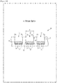
- Fig. 19 shows, as an example, a 96 well plate having ninety-six wells of the well 11 in eight rows and twelve columns. Number of the wells in the plastic container 10 is arbitrary as long as it is equal to or more than two. In addition to the 96 well plate, multi-well plates having six, twenty-four, or three hundred eighty-four wells of the well 11 are often used.
- Suitable materials for the plastic container 10 are, for example, polyethylene terephthalate (PET), polystyrene (PS), polycarbonate (PC), TAC (triacetyl cellulose), polyimide (PI), nylon (Ny), low-density polyethylene (LDPE), medium-density polyethylene (MDPE), vinyl chloride, vinylidene chloride, polyphenylene sulfide, polyether sulfone, polyethylene naphthalate, polypropylene, acrylic tmaterials such as urethane acrylate, cellulose, glass and the like.
- resins including biodegradable polymers such as polylactic acid, polyglycolic acid, polycaprolactane, or copolymers thereof can be also used.
- polyethylene terephthalate, polystyrene, and polycarbonate are preferably used, and polystyrene are particularly preferable because of their low cytotoxicity.
- the surface of the plastic container 10 can be subjected to any surface treatment (for example, irradiation with plasma, corona, microwave, electron beam, ultraviolet ray, or the like).
- the well 11 is a non-through hole and is opened on the surface of the plastic container 10. Through the opening, to the well 11 are added living cells 13 to be cultured and a culture solution 12 (for example, serum) to culture the living cells 13.
- a culture solution 12 for example, serum
- the culture solution 12 in the well 11 is constantly in contact with air in the vicinity of the opening of the well 11 both during the cell culture and in phase contrast microscopic analysis of the living cells 13. Therefore, the cultured living cells 13 are imaged (observed) with the phase-contrast microscope while being alive.
- the well 11 is formed with an opening diameter R of 0.5 mm to 2 cm, and a depth D of 2 mm to 2 cm.
- the opening diameter R of the well 11 is preferably 0.5 mm to 2 cm, and more preferably 1 mm or more, is to obtain the data converging the amount of the living cell 13 cultured under the same environment without variation.
- the opening diameter R of the well 11 is less than 2 cm, the meniscus of the liquid surface 12a of the culture solution 12 becomes conspicuous, thereby making the present invention particularly useful.
- the opening diameter R of the well 11 of 1 cm or less is particularly preferable.
- the opening diameters of the well 11 are 6 mm and 3 mm, respectively.
- the depth D of the well 11 refers to the height from the bottom 11b of the well 11 to the opening (the surface of the plastic container 10).
- the depth D of the well 11 preferably equal to or more than 2 mm to retain a sufficient amount both of medium and of the culture solution 12 to culture the living cell 13.
- the depth D of the well 11 is preferably equal to or less than 2 cm to suppress the decrease in the light intensity in the periphery of visual field due to vignetting in transmission microscopy.
- the depth D of the well 11 of3 mm equal to or less than 1 cm is particularly preferable for culturing and imaging the living cells 13.
- the amount of the culture solution 12 to be added to the well 11 is preferably equal to or less than a half of the depth D of the well 11 (see Patent Document 1).
- the said plastic container 10 has the following issues to be solved.
- This increases the burden on the experimenter because, even if the main purpose is to conduct the experiment on the living cell 13, the living cell 13 must be cultured in advance, which means that the know-how for culturing the living cell 13 is required in addition to the know-how of the experiment on the living cell 13.
- the burden on the experimenter is greater when performing an experiment using a plurality of cell lines of the living cell 13.
- the living cell 13 cultured in the well 11 of the plastic container 10 cannot be replaced, even if a defect occurs in a part thereof, because it is cultured directly on the well 11.
- the living cell 13 is cultured on the bottom of the well 11 in the plastic container 10. Because the area of the bottom of the well 11 is relatively large compared to the cells to be cultured, it is unclear where and to what extent the cells are cultured. Therefore, the cells are not uniformly cultured on the bottom of the well 11 even if the prerequisites for cell culture, amount of cells, amount of the medium, temperature, and other conditions are identical. Result may vary depending on the position of the cells in the well 11 subjected to the experiment.
- the amount of cells is greater than the amount originally needed, which results in the cost increase.
- this invention aims at providing a device for retaining and transporting cultured cells, a method for measurement of the characteristics of the cells using the said device, and a kit for cell characterization including the said device.
- the present invention provides a solution to the said issues by the following inventions described in the items (1) to (15):
- the device of the present invention is a device for retaining and transporting cells arranged in a cell culture vessel, having a flat plate-shaped base with an upper and a lower surface, a through hole formed to penetrate the said base, a cell scaffold located along the lower surface of the base for retaining the cells, and an manipulating part that can be held by a holding tool.
- Separation of the experiment and the cell culture can eliminate the need for the experimenter to do the cell culture, reducing the burden on the experimenter. Because the cell culture can be performed separately to provide the cells to the experimenter, the experimenter can conduct the experiment efficiently. In an event where the cells used in the experiment have a defect, only the defective cells can be easily replaced.
- uniform cells can be cultured by focusing on cell culture. Since the cells can be cultured in a limited area, the amount of cells required for the culture can be reduced. Since uniform cells can be cultured, the conditions before the experiment for conducting the comparative experiment and preconditions thereof can be the same.
- the user can easily manipulate, for example, move, the device by using a holding tool such as tweezers.
- the device of the present invention further comprises a medium storage space forming part that forms a medium storage space above the said through hole.
- the medium storage space to be formed above the through hole, so that the medium can be stably stored in the medium storage space.
- additional medium can be stably stored on the base, it is possible to provide fresh medium to the cells retained on the scaffold, and the cells can be stably cultured for a longer period.
- the device of the present invention is characterized in that it has manipulating part protruding from the upper surface of the said base.
- the user can easily manipulate the device using a holding tool such as tweezers.
- the device of the present invention is characterized in that the said manipulating part is formed concaving from the upper surface of the said base.
- the thickness of the device can be reduced.
- the device of the present invention comprises an air vent that penetrates the said base.
- the device of the present invention is characterized in that the said through hole has a shape such that it narrows from a surface where the said protrusion is formed towards the opposite surface.
- the device of the present invention is characterized in that at least the said base is made of a material having a specific gravity heavier than the medium.
- the device can be placed easily in the medium.
- the device can be in close contact with the objects thereunder, such as electrodes or the like.
- the device of the present invention is characterized in that the said cell scaffold is a thin fiber sheet.
- the thickness of the device can be made thin and compact.
- the device of the present invention is characterized in that the said cell scaffold comprise biomaterials.
- the device of the present invention is characterized in that the said cell scaffold accommodate cardiac myocytes or nerve cells.
- the device of the present invention is described using the device 100 as an example.
- the device 100 is a device arranged in a well of a 96 well plate for culturing cells in the medium.
- the cells cultured in the well are used in predefined experiments and tests.
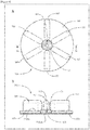
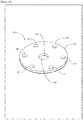
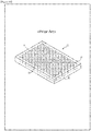
- Fig. 1 , Fig. 2 and Fig. 3 are a perspective view of the device 100, a plan view thereof, and an X1-X1 cross-section of Fig. 2 , respectively.
- the device 100 comprises a base 101, a through hole 103, a cell scaffold 105, and a manipulating part 107.
- the base 101 has a shape of a flat disk as shown in Fig. 2 , and has an upper surface P101a and a lower surface P101b as shown in Fig. 3 .
- the base 101 is made of a resin, such as polycarbonate, of which the specific gravity is larger than that of the medium. Because the device 100 including the base 101 needs to be located in the medium, the specific gravity of the base 101 and the like is determined to be, for example, 1.05 to 1.1 or more, by taking into account the specific gravity of the device 100 in relation to the medium and the buoyancy force generated in the device 100 in relation to the medium.
- the size of the base 101 is approximately 6 mm in diameter R101 (see Fig. 2 ) and approximately 0.5 mm in thickness L101h (see Fig. 3 ).
- the through hole 103 is formed from the upper surface P101a to the lower surface P101b of the base 101 so as to penetrate the base 101.
- the through hole 103 is formed as a cylindrical shape, concentrically with the base 101.
- the diameter of the through hole 103 is approximately 1 mm.
- the cell scaffold 105 is formed by a fiber sheet made of a polymeric material.
- the said polymeric material can be any materials as long as it does not exhibit cytotoxicity when the cells are cultured in contact with the said fiber sheet, and can be biodegradable or non-biodegradable, depending on the intended use of the cell sheet obtained by culturing the cells in contact with the fiber sheet
- biodegradable polymer materials include, for example, copolymers of polylactic acid and polyglycolic acid (PLGA), polyglycolic acid (PGA), polylactic acid (PLA), polyvinyl alcohol (PVA), polyethylene glycol (PEG), polyethylene vinyl acetate (PEVA), and polyethylene oxide (PEO), but are not limited to these.
- PLGA is preferably used because it is a safe material known to be hydrolyzed in vivo into lactic acids and glycolic acids originally present in living organisms, which are decomposed into water and carbon dioxide and then discharged from the body.
- PLA polylactic acid
- PGA polyglycolic acid
- non-biodegradable polymer material examples include, for example, polystyrene (PS), polycarbonate (PC), polymethyl methacrylate (PMMA), polyvinyl chloride, polyethylene terephthalate (PET), polyamide (PA), and polymethyl glutarimide (PMGI), but are not limited to these.
- PS polystyrene
- PC polycarbonate
- PMMA polymethyl methacrylate
- PET polyethylene terephthalate
- PA polyamide
- PMGI polymethyl glutarimide
- PS polystyrene
- the cell scaffold 105 has a thin disc shape and is positioned along the lower surface P101b of the base 101.
- the cell scaffold 105 is disposed on the lower surface P101b of the base 101 by applying an adhesive to an adhesive region RA of the lower surface P101b of the base 101 and then crimping them together.
- the adhesive is applied to the lower surface P101b of the base 101 so as not to protrude from the through hole 103 when the cell scaffold 105 is disposed on the lower surface P101b of the base 101.
- the adhesive is absorbed into the gap of the cell scaffold 105 comprising a fiber sheet, and become integrated with the cell scaffold 105.
- KE45 can be used as the adhesive.
- Biomaterials such as cardiac myocytes and nerve cells and the like can be cultured three-dimensionally and retained in the through hole 103 of the cell scaffold 105.
- the biomaterial refers to (1) one or more cells or cell types, (2) one or more tissues or tissue types, or (3) organs or a part thereof.
- the cells include, for example, muscle cells such as cardiac myocytes and smooth muscle cells, hepatocytes as parenchymal cells of the liver, Kupffer cells, endothelial cells such as vascular endothelial cells and corneal endothelial cells, fibroblasts, osteoblasts, osteoclasts, periodontal ligament-derived cells, epidermal cells such as epidermal keratinocytes, epithelial cells such as tracheal epithelial cells, gastrointestinal epithelial cells, cervical epithelial cells, and corneal epithelial cells, mammary glandular cells, pericytes, renal cells, knees Langerhans islet cells, nerve cells such as peripheral nerve cells and optic nerve cells, chondrocytes, and bone cells.
- muscle cells such as cardiac myocytes and smooth muscle cells
- hepatocytes as parenchymal cells of the liver Kupffer cells
- endothelial cells such as vascular endothelial cells and corneal endothelial cells
- cardiac myocytes include pluripotent stem cells such as cells derived from ES cells or iPS cells.
- nerve cells include peripheral nerve cells and optic nerve cells.
- the manipulating part 107 is formed so that it protrudes from the upper surface P101a (see Fig. 3 ) of the base 101.
- the manipulating part 107 is formed in a plurality and radially on the upper surface P101a of the base 101, with the through hole 103 as the center.
- six manipulating parts 107 are arranged on the upper surface P101a of the base 101 so that the angle between the adjacent manipulating part 107 is 60 degrees.
- Each manipulating part 107 has an upper surface arc shape, and a rectangular shape with a semicircle in the lateral direction in the cross-section along the upper surface P101a of the base 101.
- the manipulating part 107 is made of a resin material such as polycarbonate, and is formed integrally with the base 101.
- the size of each manipulating part 107 is approximately 2.5 mm in the length in the longitudinal direction L107a (see Fig. 2 ), approximately 0.5 mm in the length in the lateral direction L107b (see Fig. 2 ), and approximately 1.3 mm in the height L107h (see Fig. 3 ).
- the user can easily hold and manipulate the manipulating part 107 with tweezers or the like, simply by adjusting the angle of the wrist, regardless of the positional relationship between the user and the manipulating part 107 when placing the device 100 in the well W1.
- the user can easily manipulate the manipulating part 107.
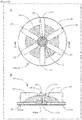
- Fig, 4 and Fig. 5 are used to explain how to use the device 100, divided into two sections: when cells are cultured and retained in the device 100, and when the device 100 retaining the cells are manipulated.
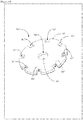
- A shows a plan view of the device 100 where the suspension CS is stored, and B shows an X4-X4 cross-section of Fig. 4-A .
- Fig. 5 A shows a plan view of the device 100 where the medium is stored, and B shows an X5-X5 cross-section of Fig. 5-A .
- cell suspension is dropped into the inside of the through hole 103 using a pipette or the like. This allows the cell suspension to be stored inside the through hole 103 as shown in Fig. 4-A .
- the surface tension of the cell suspension allows the cell suspension to be stored in the inside of the through hole 103 until the shape of the cell suspension becomes convex from the upper surface P101a of the base 101 upwardly without flowing out of the through hole 103, as shown in FIG. 4B .
- the cell suspension can be stored in the through hole 103 until it projects from the upper surface P101a of the base 101 but without flowing over out of the through hole 103 due to the surface tension of the suspension. If the base 101 is made of a hydrophobic material, the cell suspension can be more stably stored inside the through hole 103.
- a pipette or the like is used to store the medium on the upper surface P101a of the base 101 (see Fig. 5-B ) as shown in Fig. 5-A .
- a part of the space above the upper surface P101a of the base 101 functions as a medium storage space
- the other part of the upper surface P101a of the base 101 functions as a space for forming the medium storage space.
- the surface tension allows the medium to be stored in a convex shape upwardly within the upper surface P101a of the base 101.
- the base 101 is made of a hydrophobic material, the medium can be stored more stably convexly on the upper surface P101a of the base 101.
- the amount of the medium to be added is, for example, approximately 20 ⁇ l in the case of culturing cardiac myocytes in the device 100 having a diameter R101 of the base 101 is approximately 6 mm (see Fig. 2 ), which fits to the well W1 of a 96 multi-well plate.
- the manipulating part 107 is held by a holding tool such as tweezers or the like.
- a holding tool such as tweezers or the like.
- the device 100 is transferred from outside the well W1 of the multi-well plate to inside the well1, as shown in Fig. 6 , by holding the manipulating part 107 with a holding tool such as tweezers or the like.
- the position and orientation of the device 100 is changed within the well W1.
- the device 100 can be easily manipulated with the manipulating part 107.
- the spillage of the medium can be prevented by holding the manipulating part 107 protruding from the medium with a holding tool.
- the device 100 can be easily transferred by holding the manipulating part 107 with a holding tool onto, for example, the electrode of an MEA (Multi-Electrode Array) probe for the measurement of the electrical characteristics of the cells.
- MEA Multi-Electrode Array
- Example 1 the medium was placed on the upper surface P101a of the base 101 by utilizing the surface tension of the medium and the hydrophobicity of the base 101 and the manipulating part 107.
- the device 200 an example of the device of the present invention, has a medium storage space forming part 209 that forms a medium storage space S209 for storing the medium above the through hole 103, which facilitates addition of the medium on the upper surface P101a of the base 101.
- a medium storage space forming part 209 that forms a medium storage space S209 for storing the medium above the through hole 103, which facilitates addition of the medium on the upper surface P101a of the base 101.
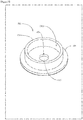
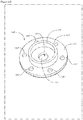
- Fig. 7 is a perspective view of the device 200.
- the device 200 comprises a base 101, a through hole 103, a cell scaffold 105, and a medium storage space forming part 209.
- the medium storage space forming part 209 is formed so as to project from the upper surface P101a of the base 101 (see Fig. 3 ).
- the medium storage space forming part 209 is formed in a cylindrical shape on the upper surface P101a of the base 101 with the through hole 103 at its center.
- the medium storage space forming part 209 is made of a resin material similar to the base 101, and is formed in an integrated manner with the base 101.
- a medium storage space S209 can be formed above the through hole 103.
- the size of the medium storage space forming part 209 is approximately 4.4 mm in the inner diameter, approximately 5.4 mm in the outer diameter, and approximately 1.3 mm in the height in the case of the device 200 matching to the well W1 of the 96 multi-well plate.
- the medium storage space forming part 209 is formed so as to project from the upper surface P101a of the base 101, and therefore also functions as a manipulating part.
- Fig. 7 is used to explain how to use the device 200, divided into two sections: when cells are cultured and retained in the device 200, and when the device 200 retaining the cells are manipulated.
- A is a perspective view of the device 200 where the suspension CS is stored.
- the procedure of culturing and retaining cells on the cell scaffold 105 in the device 200 is similar to that for the device 100.
- a pipette or the like is used to store the medium in the medium storage space S209 formed by the medium storage space forming part 209 that is located on the upper surface P101a of the base 101.
- the medium was stored in a convex shape upwardly within the upper surface P101a of the base 101 due to the surface tension of the added medium and/or the hydrophobicity of the base 101 (see Fig. 5-B ), and therefore it may be difficult to stably store the medium.
- the medium storage space S209 is formed by the medium storage space forming part 209 in the device 200, which enables stable storage of the medium in the medium storage space S209 on the upper surface P101a of the base 101.
- the medium storage space forming part 209 and the base 101 is held by a holding tool such as tweezers or the like. This allows the device 200 to be easily manipulated.
- Example 2 the device for retaining and transporting cells 200 had a medium storage space formingpart209 formed in a cylindrical shape.
- the device 300 an example of the device of the present invention, has a plurality of medium storage space forming part 209.
- the similar configurations to Example 1 and Example 2 are marked with the same signs, and detailed descriptions are omitted.
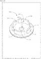
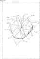
- Fig. 8 is a perspective view of the device 300.
- the device 300 comprises a base 101, a through hole 103, a cell scaffold 105, and a medium storage space forming part 309.
- a plurality of medium storage space forming part 309 is formed so as to project from the upper surface P101a of the base 101 (see Fig. 3 ).
- the medium storage space forming part 309 is formed independently of the other adjacent medium storage space forming part 309 with a gap.
- a plurality of medium storage space forming part 309 forms a cylindrical shape centered on the through hole 103 on the upper surface P101a of the base 101, and the medium storage space S309 inside the medium storage space formation part 309.
- the medium storage space forming part 309 is made of polycarbonate similar to the base 101, and is formed in an integrated manner with the base 101.
- the medium storage space forming part 309 is formed so as to project from the upper surface P101a of the base 101, and therefore also functions as a manipulating part.
- Fig.9 is used to explain how to use the device 300, divided into two sections: when cells are cultured and retained in the device 200, and when the device 200 retaining the cells are manipulated.
- Fig. 9 shows a plan view of the device 300 where the suspension CS and the medium are stored.
- the procedure of culturing and retaining cells on the cell scaffold 105 in the device 300 is similar to that for the device 100. Also, the procedure of storing medium in the medium storage space S309 formed by the medium storage space forming part 309 in the device 300 is similar to that for the device 200.
- the medium storage space S309 is formed by a plurality of medium storage space forming parts 309. Namely, it means that the medium storage space S309 will have an opening leading to the outside of the medium storage space formation portion 309, but as shown in Fig. 9 , the surface tension of the medium to be added and/or the hydrophobic nature of the base portion 101 allows the medium to be stably stored in the medium storage space S309 (see above, Fig. 8 ).
- the medium storage space forming part 309 and the base 101 is held by a holding tool such as tweezer or the like. This allows the device 200 to be easily manipulated.
- Example 1 when placing the device 100 in the well W1, it is necessary to submerge the device 100 in the medium stored in the well W1. However, if there is not much difference between the inner diameter of the well W1 and the diameter R101 (see Fig. 2 ) of the base 101 of the device 100, the medium may enter into the gap between the side surface of the well W1 and the device 100, and the air entering under the device 100 may not escape outside from the well W1 and the device 100.
- the device 400 which is an example of the device for retaining and transporting cells of the present invention, has the base 101 and an air vent 413 that penetrates the cell scaffold 105 located at the bottom of the base 101, which allows the air that has entered under the device 400 to be easily discharged outside.
- the same configuration as in Example 1 are marked with the same sign and detailed description are omitted.
- Fig. 10 is a perspective view of the device 400.
- the device 400 comprises a base 101, a through hole 103, a cell scaffold 105, a manipulating part 107, and an air vent 413.
- the air vent 413 is formed as a rectangular notch from the outer periphery of the base 101 towards the inside, and is formed so as to penetrate the base 101 and the cell scaffold 105. It enables easy discharge of the air that entered below the device 400 from between the base 101 and the side surface of the well W1.
- the method of using the device 400 is similar to that the device 100. However, it is necessary to immerse the device 400 in the medium in the well W1 while confirming that the air escapes from the air vent 413.
- the device for retaining and transporting cells 1700 of the present invention has a simple structure for easier use in which cells can be easily cultured.
- the similar configurations to Example 1 are marked with the same signs, and detailed descriptions are omitted.
- Fig. 20 is a perspective view of the device 1700.
- the device 1700 has a base 1701, a through hole 1703, a cell culture holding part 105, a manipulating part 1707, and an air vent 1711.
- the base 1701 has a thin disc shape and is made of, for example, polycarbonate.
- the through hole 1703 is formed in the center of the base 1701.
- the base 1701 also has an upper surface P1701a and a lower surface P1701b (see Fig. 21 ).
- the through hole 1703 is formed so as to penetrate the base 1701 from the upper surface P1701a to the lower surface P1701bof the base 1701.
- the through hole 1703 has a shape of a circular truncated cone that narrows from the upper surface P1701a where the manipulating part 1707 is formed towards the lower surface P1701b. Therefore, the opening on the upper surface P1701a of the base 1701 can be enlarged, which enables easy dropping of the suspension into the through hole 1703. Furthermore, since the capacity of the through hole 1703 can be increased, a larger volume of the suspension can be retained in the through hole 1703.
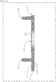
- the shape of the through hole 1703 is described here with reference to Fig. 21 .
- A shows the axial cross-section of the base 1701 and the manipulating part 1707.
- the through hole 1703 has an inclined part S1703 at a prescribed distance from the lower surface P1701b of the base 1701 towards the upper surface P1701a.
- the inclined part S1703 is formed as a surface inclined by a prescribed angle from the axial direction.
- the axial cross-section of the inclined part S1703 is an inclined straight line.
- the manipulating part 1707 is formed so as to project from the upper surface P1701a of the base 1701.
- the manipulating part 1707 is formed in parallel on the upper surface P1701a of the base 1701 across the through hole 1703.
- the manipulating part 1707 can be formed apart from the through hole 1703, so that the culture solution stored in the through hole 1703 can be prevented from exceeding its own surface tension and overflowing from the through hole 1703 when culturing cells.
- the device 1700 can be easily manipulated by holding with tweezers etc.
- the manipulating part 1707 is made of a resin material such as polycarbonate as the base 1701, and is formed integrally manner with the base 1701.
- the manipulating part 1707 allows the user to hold it with tweezers or the like, and to easily manipulate the device 1700.
- the air vent 1711 is formed as an area in which a part of the outer peripheral part of the base 1701 is cut off.
- the cell culture holding part 1701 located below the base 1701 is also formed in the same shape as the base 1701. It enables easy discharge of the air that has entered below the device 1700 when putting the device 1700 in a cell culture container such as one well of a multi-well plate.
- the method of using the device 1700 is similar to that the device 100 - 400.
- the method of using the device for retaining and transporting cells 1700 when measuring cell characteristics is described here by taking an example of measuring an extracellular potential generated by cell activity of cardiac myocytes that is formed in the device for retaining and transporting cells 1700.
- An MEA (Multi-Electrode Array) probe P is used for measuring the extracellular potential.
- the MEA probe P is a device for measuring the extracellular potential generated by cellular activity.
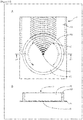
- Fig. 22 shows a brief description of the MEA probe P.
- Fig. 21-A is a plan view of the MEA probe P
- Fig. 22-B is an X4-X4 cross-section of the MEA probe P shown in Fig. 22-A .
- the MEA probe P has a substrate PB and a molten wall PW.
- the substrate PB has a thin plate shape, and the molten wall PW is formed on the substrate PB.
- the melted wall PW has a cylindrical shape with one end open, and stores a medium inside, forming a cell arrangement space PS for placing the cells to be tested.
- the MEA probe P has also measurement electrodes E1 and reference electrodes E2.
- the measurement electrodes E1 are formed along with the substrate PB at approximately the center of the molten wall PW.
- the measurement electrodes E1 is arranged in a 4 ⁇ 4 matrix.
- a prescribed number of the reference electrodes E2 are arranged around the measurement electrodes E1.
- the MEA probe P measures the extracellular potential associated with the cellular activities based on the potential difference between the measurement electrodes E1 and the reference electrodes E2.
- a lead line (dotted line in the figure) is arranged from each of the measurement electrodes E1 and the reference electrodes E2.
- the device 1700 where cardiac myocytes are cultured is placed in the cell arrangement space PS. At this time, the device 1700 is arranged so that the regions corresponding to the through hole 1703 in the cell culture holding part 105 is located on the measurement electrodes E1 of the MEA probe P.
- the MEA probe P is then used to measure the extracellular potential associated with the cellular activities of the cardiac myocytes cultured in the device 1700.
- the extracellular potential of the cultured cardiac myocytes was measured using the device 1700 that is formed using polycarbonate and that has a base 1701 (diameter: 6 mm, thickness: 0.7 mm), a through hole 1703 (diameter: 1.5 mm), a cell culture holding part 105 made of an oriented fiber sheet with a pitch of 10 ⁇ m, a manipulating part 1707, and the air vent section 1711, and the MEA probe P (MED64 System, Alpha MED Scientific Inc.).
- the oriented fiber sheet of the cell culture holding part 105 was seeded with human iPS cell-derived cardiac myocytes, and the cardiac myocytes were cultured for seven days at 37°C with 5% CO 2 .
- the pitch of the fiber sheet refers to the distance between the core lines of adjacent fibers among the fibers composing of the fiber sheet.
- the drug response of the cultured cardiac myocytes can be measured by means of the extracellular potential by changing the conditions of the drug to be administered to the cultured cardiac myocytes.
- Dofetilide (a drug for atrial fibrillation, Sigma) was chosen as the drug to be administered.
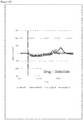
- the device 1700 where the cardiac myocytes were cultured was placed in the cell arrangement space PS of the MEA probe P filled with medium. Then the extracellular potentials of each dose: DMSO (Dimethyl Sulfoxide) alone; dofetilide: 0.0003 ⁇ M; dofetilide: 0.001 ⁇ M; and dofetilide: 0.003 ⁇ M. The result is shown in Fig. 23 .
- DMSO Dimethyl Sulfoxide
- Fig. 23 show that the first and the second peak potentials caused by the beating of the cardiac myocytes change depending on the dose. Specifically, as the concentration of the dofetilide increases, the time required from the first peak potential to the second peak potential becomes longer. It means that the time between the first peak and the second peak is prolonged depending on the concentration. Therefore, the drug response as a cellular characteristic can be examined using the device 1700.
- the base 101 can be formed by a metal, particularly that having low or no biotoxicity instead of a resin material. It enables adjustment of the weight of the device.
- the base 101 may be formed by combining a resin material and a metal, for example in the same shape, or by using a metal as a part of the resin material.
- the device for retaining and transporting cells 100 can also be formed by different components with different molding materials, such as using the resin-made base 101 and the metal-based manipulating part 107.
- the base 101 and the manipulating part 107 can be formed by combining separate components made of the same material. The same applies to the other embodiments.
- the device for retaining and transporting cells of the present invention can be used, for example, for drug efficacy testing of cells using 96 multi-well plates.
Landscapes
- Health & Medical Sciences (AREA)
- Life Sciences & Earth Sciences (AREA)
- Wood Science & Technology (AREA)
- Organic Chemistry (AREA)
- Engineering & Computer Science (AREA)
- Bioinformatics & Cheminformatics (AREA)
- Chemical & Material Sciences (AREA)
- Zoology (AREA)
- Biomedical Technology (AREA)
- Sustainable Development (AREA)
- Microbiology (AREA)
- Biotechnology (AREA)
- Biochemistry (AREA)
- General Engineering & Computer Science (AREA)
- General Health & Medical Sciences (AREA)
- Genetics & Genomics (AREA)
- Immunology (AREA)
- Clinical Laboratory Science (AREA)
- Molecular Biology (AREA)
- Apparatus Associated With Microorganisms And Enzymes (AREA)
- Micro-Organisms Or Cultivation Processes Thereof (AREA)
Applications Claiming Priority (2)
| Application Number | Priority Date | Filing Date | Title |
|---|---|---|---|
| JP2018035458 | 2018-02-28 | ||
| PCT/JP2019/007361 WO2019167960A1 (fr) | 2018-02-28 | 2019-02-26 | Dispositif de retenue et de transport de cellules |
Publications (2)
| Publication Number | Publication Date |
|---|---|
| EP3760701A1 true EP3760701A1 (fr) | 2021-01-06 |
| EP3760701A4 EP3760701A4 (fr) | 2021-12-08 |
Family
ID=67805006
Family Applications (1)
| Application Number | Title | Priority Date | Filing Date |
|---|---|---|---|
| EP19761426.6A Withdrawn EP3760701A4 (fr) | 2018-02-28 | 2019-02-26 | Dispositif de retenue et de transport de cellules |
Country Status (4)
| Country | Link |
|---|---|
| US (1) | US20200407674A1 (fr) |
| EP (1) | EP3760701A4 (fr) |
| JP (1) | JP7441521B2 (fr) |
| WO (1) | WO2019167960A1 (fr) |
Families Citing this family (4)
| Publication number | Priority date | Publication date | Assignee | Title |
|---|---|---|---|---|
| JPWO2020085423A1 (ja) * | 2018-10-25 | 2021-10-07 | 株式会社幹細胞&デバイス研究所 | 細胞保持装置 |
| JPWO2021006286A1 (fr) * | 2019-07-10 | 2021-01-14 | ||
| US20250115836A1 (en) * | 2020-11-25 | 2025-04-10 | Koninklijke Philips N.V. | Devices for cell or tissue culturing, or testing in vitro muscle tissue |
| JP7687607B2 (ja) * | 2021-03-23 | 2025-06-03 | 日本毛織株式会社 | 神経細胞ネットワーク、その製造方法、その作製キット、並びに神経細胞の評価方法及び化合物の評価方法 |
Family Cites Families (20)
| Publication number | Priority date | Publication date | Assignee | Title |
|---|---|---|---|---|
| CH586282A5 (fr) * | 1974-10-22 | 1977-03-31 | Wild Dr & Co Ag | |
| CA2055966C (fr) * | 1990-12-19 | 1995-08-01 | Oresta Natalia Fedun | Dispositif d'insertion de culture cellulaire |
| JPH0615499U (ja) * | 1992-08-04 | 1994-03-01 | 住友ベークライト株式会社 | 培養用小片 |
| AU658079B2 (en) * | 1992-09-28 | 1995-03-30 | Becton Dickinson & Company | Cell culture insert |
| US5366893A (en) * | 1993-01-13 | 1994-11-22 | Becton, Dickinson And Company | Culture vessel |
| EP0638640B1 (fr) * | 1993-08-12 | 2000-03-22 | Becton, Dickinson and Company | Récipient de culture |
| US5635396A (en) * | 1995-08-30 | 1997-06-03 | Becton, Dickinson And Company | Coverslip holder |
| US20040091397A1 (en) * | 2002-11-07 | 2004-05-13 | Corning Incorporated | Multiwell insert device that enables label free detection of cells and other objects |
| JP2006271369A (ja) * | 2005-03-02 | 2006-10-12 | Nippon Sheet Glass Co Ltd | 生化学用容器 |
| WO2006123570A1 (fr) * | 2005-05-17 | 2006-11-23 | Kuraray Co., Ltd. | Recipient de culture cellulaire |
| JP2007167002A (ja) * | 2005-12-22 | 2007-07-05 | Asahi Techno Glass Corp | 細胞培養用カセット、細胞培養用カセット着脱用治具及び細胞培養装置 |
| JP2009022247A (ja) * | 2007-07-23 | 2009-02-05 | Toshiba Corp | 培養容器及び培養組織回収方法 |
| JP2010063411A (ja) * | 2008-09-11 | 2010-03-25 | Teijin Ltd | 細胞培養用基材 |
| JP2016067322A (ja) | 2014-09-30 | 2016-05-09 | 富士フイルム株式会社 | プラスチック製容器 |
| EP3208328A4 (fr) * | 2014-10-16 | 2018-09-05 | Kyoto University | Fragment de tissu |
| JP2016093149A (ja) * | 2014-11-14 | 2016-05-26 | 真志 池内 | 細胞培養装置および細胞培養方法 |
| JP6480285B2 (ja) * | 2015-08-04 | 2019-03-06 | 豊田合成株式会社 | 細胞培養器具およびその製造方法 |
| WO2018042532A1 (fr) * | 2016-08-31 | 2018-03-08 | 株式会社メニコン | Récipient de culture cellulaire |
| JP6454830B1 (ja) * | 2017-10-10 | 2019-01-16 | 株式会社サイフューズ | 細胞トレイおよび不織布組立部材 |
| WO2019087991A1 (fr) * | 2017-10-30 | 2019-05-09 | 株式会社幹細胞&デバイス研究所 | Dispositif d'aide à la mesure du potentiel extracellulaire |
-
2019
- 2019-02-26 EP EP19761426.6A patent/EP3760701A4/fr not_active Withdrawn
- 2019-02-26 US US16/975,659 patent/US20200407674A1/en not_active Abandoned
- 2019-02-26 JP JP2020503533A patent/JP7441521B2/ja active Active
- 2019-02-26 WO PCT/JP2019/007361 patent/WO2019167960A1/fr not_active Ceased
Also Published As
| Publication number | Publication date |
|---|---|
| JP7441521B2 (ja) | 2024-03-01 |
| EP3760701A4 (fr) | 2021-12-08 |
| US20200407674A1 (en) | 2020-12-31 |
| WO2019167960A1 (fr) | 2019-09-06 |
| JPWO2019167960A1 (ja) | 2021-02-12 |
Similar Documents
| Publication | Publication Date | Title |
|---|---|---|
| EP3760701A1 (fr) | Dispositif de retenue et de transport de cellules | |
| CN102947710B (zh) | 悬滴装置、系统和/或方法 | |
| CA2893971C (fr) | Constructions de tissu cardiaque et leurs procedes de fabrication | |
| EP2917326B1 (fr) | Dispositif de culture cellulaire pour la génération et la culture d'agrégats cellulaires, procédé de production dudit dispositif et utilisation dudit dispositif | |
| US20090061513A1 (en) | Cell sorting and cell cultivation methods | |
| KR20140048733A (ko) | 다중 웰 플레이트 및 상기 다중 웰 플레이트를 이용한 표적 물질 분석 방법 | |
| US20090053813A1 (en) | Multiplexed electroporation apparatus | |
| Chen et al. | Naked liquid marbles: a robust three-dimensional low-volume cell-culturing system | |
| FI131135B1 (en) | MICROFLUIDIC CELL CULTURE DEVICE AND METHOD FOR CELL CULTURE | |
| KR20210047268A (ko) | 세포 배양 장치 및 방법 | |
| CN103649302A (zh) | 细胞培养装置、细胞培养长期观察装置、细胞长期培养方法以及细胞培养长期观察方法 | |
| CA3043708A1 (fr) | Plates-formes de puce pour la bio-impression 3d de microreseau | |
| Muniyandi et al. | Biotechnological advances and applications of human pluripotent stem cell-derived heart models | |
| Perez et al. | Protocol for 3D bioprinting mesenchymal stem cell–derived neural tissues using a fibrin-based bioink | |
| US20030219884A1 (en) | Method for carrying out electrical measurements on biological membrane bodies | |
| JP7278523B2 (ja) | 細胞培養容器 | |
| Cheng et al. | “Chip-on-a-Transwell” Devices for User-Friendly Control of the Microenvironment of Cultured Cells | |
| Kim et al. | Droplet contact-based spheroid transfer technique as a multi-step assay tool for spheroid arrays | |
| US20140178920A1 (en) | Solid support for endothelial cell growth | |
| Ott et al. | Preparation of Bunyavirus-Infected Cells for Electron Cryo-Tomography | |
| EP4613841A1 (fr) | Micropuits pour la culture d'un organoïde et dispositif de mesure d'activité électrique et/ou de stimulation de cellules dans un réseau tridimensionnel | |
| JP2015177755A (ja) | 細胞排除性を発現する溝構造 | |
| CN119677867A (zh) | 用于使用微有机球测试肝细胞毒性的方法和装置 | |
| Weber | Manufacturing of Gold Nanoelectrode Ensembles for Intracellular Recording on Living Cells | |
| Eydelnant | Digital Microfluidics for Multidimensional Biology |
Legal Events
| Date | Code | Title | Description |
|---|---|---|---|
| STAA | Information on the status of an ep patent application or granted ep patent |
Free format text: STATUS: THE INTERNATIONAL PUBLICATION HAS BEEN MADE |
|
| PUAI | Public reference made under article 153(3) epc to a published international application that has entered the european phase |
Free format text: ORIGINAL CODE: 0009012 |
|
| STAA | Information on the status of an ep patent application or granted ep patent |
Free format text: STATUS: REQUEST FOR EXAMINATION WAS MADE |
|
| 17P | Request for examination filed |
Effective date: 20200825 |
|
| AK | Designated contracting states |
Kind code of ref document: A1 Designated state(s): AL AT BE BG CH CY CZ DE DK EE ES FI FR GB GR HR HU IE IS IT LI LT LU LV MC MK MT NL NO PL PT RO RS SE SI SK SM TR |
|
| AX | Request for extension of the european patent |
Extension state: BA ME |
|
| DAV | Request for validation of the european patent (deleted) | ||
| DAX | Request for extension of the european patent (deleted) | ||
| A4 | Supplementary search report drawn up and despatched |
Effective date: 20211105 |
|
| RIC1 | Information provided on ipc code assigned before grant |
Ipc: C12M 1/12 20060101ALI20211101BHEP Ipc: C12M 3/00 20060101ALI20211101BHEP Ipc: C12M 1/00 20060101AFI20211101BHEP |
|
| STAA | Information on the status of an ep patent application or granted ep patent |
Free format text: STATUS: THE APPLICATION IS DEEMED TO BE WITHDRAWN |
|
| 18D | Application deemed to be withdrawn |
Effective date: 20240903 |