WO2019167960A1 - Dispositif de retenue et de transport de cellules - Google Patents
Dispositif de retenue et de transport de cellules Download PDFInfo
- Publication number
- WO2019167960A1 WO2019167960A1 PCT/JP2019/007361 JP2019007361W WO2019167960A1 WO 2019167960 A1 WO2019167960 A1 WO 2019167960A1 JP 2019007361 W JP2019007361 W JP 2019007361W WO 2019167960 A1 WO2019167960 A1 WO 2019167960A1
- Authority
- WO
- WIPO (PCT)
- Prior art keywords
- cell
- cell holding
- holding
- base
- transporting device
- Prior art date
- Legal status (The legal status is an assumption and is not a legal conclusion. Google has not performed a legal analysis and makes no representation as to the accuracy of the status listed.)
- Ceased
Links
Images







Classifications
-
- C—CHEMISTRY; METALLURGY
- C12—BIOCHEMISTRY; BEER; SPIRITS; WINE; VINEGAR; MICROBIOLOGY; ENZYMOLOGY; MUTATION OR GENETIC ENGINEERING
- C12M—APPARATUS FOR ENZYMOLOGY OR MICROBIOLOGY; APPARATUS FOR CULTURING MICROORGANISMS FOR PRODUCING BIOMASS, FOR GROWING CELLS OR FOR OBTAINING FERMENTATION OR METABOLIC PRODUCTS, i.e. BIOREACTORS OR FERMENTERS
- C12M45/00—Means for pre-treatment of biological substances
- C12M45/22—Means for packing or storing viable microorganisms
-
- C—CHEMISTRY; METALLURGY
- C12—BIOCHEMISTRY; BEER; SPIRITS; WINE; VINEGAR; MICROBIOLOGY; ENZYMOLOGY; MUTATION OR GENETIC ENGINEERING
- C12M—APPARATUS FOR ENZYMOLOGY OR MICROBIOLOGY; APPARATUS FOR CULTURING MICROORGANISMS FOR PRODUCING BIOMASS, FOR GROWING CELLS OR FOR OBTAINING FERMENTATION OR METABOLIC PRODUCTS, i.e. BIOREACTORS OR FERMENTERS
- C12M23/00—Constructional details, e.g. recesses, hinges
- C12M23/02—Form or structure of the vessel
- C12M23/04—Flat or tray type, drawers
-
- C—CHEMISTRY; METALLURGY
- C12—BIOCHEMISTRY; BEER; SPIRITS; WINE; VINEGAR; MICROBIOLOGY; ENZYMOLOGY; MUTATION OR GENETIC ENGINEERING
- C12M—APPARATUS FOR ENZYMOLOGY OR MICROBIOLOGY; APPARATUS FOR CULTURING MICROORGANISMS FOR PRODUCING BIOMASS, FOR GROWING CELLS OR FOR OBTAINING FERMENTATION OR METABOLIC PRODUCTS, i.e. BIOREACTORS OR FERMENTERS
- C12M23/00—Constructional details, e.g. recesses, hinges
- C12M23/02—Form or structure of the vessel
- C12M23/12—Well or multiwell plates
-
- C—CHEMISTRY; METALLURGY
- C12—BIOCHEMISTRY; BEER; SPIRITS; WINE; VINEGAR; MICROBIOLOGY; ENZYMOLOGY; MUTATION OR GENETIC ENGINEERING
- C12M—APPARATUS FOR ENZYMOLOGY OR MICROBIOLOGY; APPARATUS FOR CULTURING MICROORGANISMS FOR PRODUCING BIOMASS, FOR GROWING CELLS OR FOR OBTAINING FERMENTATION OR METABOLIC PRODUCTS, i.e. BIOREACTORS OR FERMENTERS
- C12M25/00—Means for supporting, enclosing or fixing the microorganisms, e.g. immunocoatings
- C12M25/02—Membranes; Filters
-
- C—CHEMISTRY; METALLURGY
- C12—BIOCHEMISTRY; BEER; SPIRITS; WINE; VINEGAR; MICROBIOLOGY; ENZYMOLOGY; MUTATION OR GENETIC ENGINEERING
- C12M—APPARATUS FOR ENZYMOLOGY OR MICROBIOLOGY; APPARATUS FOR CULTURING MICROORGANISMS FOR PRODUCING BIOMASS, FOR GROWING CELLS OR FOR OBTAINING FERMENTATION OR METABOLIC PRODUCTS, i.e. BIOREACTORS OR FERMENTERS
- C12M25/00—Means for supporting, enclosing or fixing the microorganisms, e.g. immunocoatings
- C12M25/02—Membranes; Filters
- C12M25/04—Membranes; Filters in combination with well or multiwell plates, i.e. culture inserts
-
- C—CHEMISTRY; METALLURGY
- C12—BIOCHEMISTRY; BEER; SPIRITS; WINE; VINEGAR; MICROBIOLOGY; ENZYMOLOGY; MUTATION OR GENETIC ENGINEERING
- C12M—APPARATUS FOR ENZYMOLOGY OR MICROBIOLOGY; APPARATUS FOR CULTURING MICROORGANISMS FOR PRODUCING BIOMASS, FOR GROWING CELLS OR FOR OBTAINING FERMENTATION OR METABOLIC PRODUCTS, i.e. BIOREACTORS OR FERMENTERS
- C12M25/00—Means for supporting, enclosing or fixing the microorganisms, e.g. immunocoatings
- C12M25/14—Scaffolds; Matrices
Definitions
- the present invention relates to a cell holding and transporting device, and more particularly, to a device that can easily move a held cell.
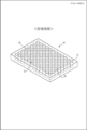
- the plastic container 10 is a container for culturing living cells such as living cells and tissues, and is a container for imaging (or observing) the cultured living cells with a phase contrast microscope. is there.
- the plastic container 10 is a so-called multi-well plate, and has a plurality of wells 11 opened in a circular shape.
- the well 11 is a recess for storing a living cell to be imaged after culturing and a culture solution for culturing the living cell.
- a 96-well plate having 96 wells 11 in 8 rows and 12 columns is shown as an example, but the plastic container 10 only needs to have at least two wells 11. The number of is arbitrary.
- a multiwell plate having 6, 24, or 384 wells 11 is often used.
- Suitable materials for the plastic container 10 include, for example, polyethylene terephthalate (PET), polystyrene (PS), polycarbonate (PC), TAC (triacetyl cellulose), polyimide (PI), nylon (Ny), low density polyethylene (LDPE). ), Medium density polyethylene (MDPE), vinyl chloride, vinylidene chloride, polyphenylene sulfide, polyether sulfone, polyethylene naphthalate, polypropylene, urethane acrylate and other acrylic materials, cellulose, glass and the like.
- a resin such as a biodegradable polymer such as polylactic acid, polyglycolic acid, polycaprolactan, or a copolymer thereof can be used.
- polyethylene terephthalate, polystyrene, and polycarbonate can be preferably used, and polystyrene can be particularly preferably used. This is because the cytotoxicity is low.
- the surface of the plastic container 10 may be subjected to any surface treatment (for example, irradiation with plasma, corona, microwave, electron beam, ultraviolet ray, etc.).
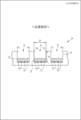
- the well 11 is a non-through hole and is opened on the surface of the plastic container 10.
- a living cell 13 to be cultured and a culture solution 12 (for example, serum solution) for culturing the living cell 13 are injected into the well 11 from the opening.
- the culture solution 12 injected into the well 11 is always in the vicinity of the opening of the well 11 during culturing of the living cells 13 and during imaging with a phase contrast microscope. Contact with air. For this reason, the cultured living cells 13 are imaged (observed) with a phase contrast microscope while alive.
- the well 11 has an opening diameter R of 0.5 mm or more and less than 2 cm, and a depth D of 2 mm or more and less than 2 cm.
- the reason why the diameter R of the opening of the well 11 is 0.5 mm or more and less than 2 cm is that it is preferable for obtaining data that converges the number of living cells 13 cultured in the same environment without variation. .
- the diameter R of the opening of the well 11 is more preferably 1 mm or more. When the diameter R of the opening of the well 11 is less than 2 cm, the meniscus of the liquid surface 12a of the culture solution 12 becomes prominent. Therefore, the present invention is particularly useful, and the diameter R of the opening of the well 11 is 1 cm or less. It is particularly suitable for the case.
- the diameter of the opening of the well 11 is 6 mm, for example.
- the diameter of the opening of the well 11 is 3 mm, for example. is there.
- the depth D of the well 11 is the height from the bottom surface 11b of the well 11 to the opening (the surface of the plastic container 10), and the depth D of the well 11 is formed to be 2 mm or more. This is because a sufficient medium for culturing 13 and a sufficient amount of the culture solution 12 for culturing the living cells 13 are secured.
- the depth D of the well 11 is formed to be less than 2 cm in order to prevent a decrease in the amount of light in the peripheral visual field due to vignetting when observing with a transmission microscope. If the depth D of the well 11 is in the range of 3 mm or more and 1 cm or less, it is particularly suitable for the culture and imaging of the living cells 13. Moreover, it is preferable that the quantity of the culture solution 12 put into the well 11 is 1/2 or less of the depth D of the well 11 (refer patent document 1 above).
- the above-described plastic container 10 has the following points to be improved.
- any experiment is performed using predetermined live cells 13, it is necessary to culture the live cells 13 directly in the well 11 of the plastic container 10 before the experiment. For this reason, there exists a point which should be improved that an experiment and cell culture cannot be isolate
- the burden on the experimenter is large. In particular, when an experiment is performed using a plurality of types of living cells 13, there is a point to be improved in that the burden on the experimenter increases.
- live cells 13 are cultured at the bottom of the well 11.
- the bottom of the well 11 has a relatively large area from the cells to be cultured, and it is unclear at which position of the bottom the cells are cultured. Therefore, even if the cell culture preconditions, the number of cells, the amount of medium, the temperature, and the like are the same, the cells are not uniformly cultured at the bottom of the well 11. For this reason, even in the well 11, there is a point to be improved that there is a possibility that the result may be different depending on the cell target at which position.
- the present invention holds a cultured cell and can move the cell while holding the cell, and a cell characteristic measurement that measures a predetermined characteristic of the cell using the cell holding and conveying device It is an object of the present invention to provide a method and a kit for measuring cell characteristics including the cell holding and transporting device.
- this invention solves the said subject by providing the invention as described in the following (1) to (15).
- a cell holding and transporting device disposed in a cell culture container, A base having an upper surface and a lower surface, A through hole formed to penetrate the base, A cell scaffold located along the lower surface of the base and holding cells, An operation unit that can be clamped by a predetermined holder, A cell holding and transporting device.
- the cell holding and conveying device according to (1) comprising: (3) The operation unit is Projecting from the upper surface of the base, The cell holding and conveying device according to (1) or (2).
- the operation unit is Forming a concave shape from the upper surface of the base, The cell holding and conveying device according to (1) or (2). (5) further, An air vent passing through the base, The cell holding and conveying device according to any one of (1) to (4).
- the through hole is Having a shape that narrows from the surface on which the protruding portion is formed toward the oppositely located surface;
- At least the base is Formed of a material having a specific gravity heavier than the medium,
- the cell scaffold is A thin fiber sheet,
- the cell scaffold is Have biological material, The cell holding / transporting device according to any one of (1) to (10), wherein (12) The cell scaffold is Having predetermined cells, The cell holding and conveying device according to (11), characterized in that (13) The cell scaffold is Having cardiomyocytes or neurons, The cell holding and conveying device according to (11), characterized in that (14) (1) A cell characteristic measuring method for measuring a predetermined characteristic of a cell using the cell holding and conveying device according to any one of (13). (15) (1) A kit for measuring cell characteristics, comprising the cell holding and transporting device according to any one of (13).
- the cell holding and transporting device is a cell holding and transporting device disposed in a cell culture container, and has a flat base having an upper surface and a lower surface, a through-hole formed so as to penetrate the base, and the base A cell scaffold that holds cells and an operation unit that can be sandwiched by a predetermined holder.
- the experiment and the cell culture can be separated, the experimenter does not need to perform the cell culture, and the burden on the experimenter can be reduced. Furthermore, since only cells can be cultured and provided to the experimenter, the experimenter can be efficiently experimented. Furthermore, when a defect occurs in the cells used in the experiment, only the defective cell can be easily replaced.
- the user can easily operate, for example, move the cell holding and transporting apparatus using a holder such as tweezers.
- the cell holding and transporting device further includes a medium storage space forming unit that forms a medium storage space for storing the medium on the through hole.
- the culture medium storage space can be formed on the through-hole, the culture medium can be stably stored in the culture medium storage space.
- a medium can be additionally stored stably on the base, a fresh medium can be provided to the cells held on the scaffold member, and the cells can be stably cultured for a longer period of time. Can do.
- the cell holding and transporting device according to the present invention is characterized in that it protrudes from the upper surface of the base.
- the user can easily operate the cell holding and transporting apparatus using a holder such as tweezers.
- the cell holding and transporting device is characterized in that the operation part is formed in a concave shape from the upper surface of the base part.
- the user can easily operate the cell holding and transporting apparatus using a holder such as tweezers.
- the thickness of the cell holding and conveying device can be reduced.
- the cell holding and transporting device according to the present invention further includes an air vent that penetrates the base.
- the cell holding and transporting device is characterized in that the through hole has a shape that narrows from a surface on which the protruding portion is formed toward a surface located opposite to the through hole.
- the cell suspension for culturing the cells can be easily dropped on the cell scaffold, the cells can be easily cultured. Moreover, since the capacity
- the cell holding and transporting apparatus is characterized in that at least the base is formed of a material having a specific gravity heavier than that of the culture medium.
- the cell holding and transporting device can be easily placed in the medium.
- the pressure can be easily applied downward by its own weight, it can be brought into close contact with an arrangement such as an electrode arranged at the lower part of the cell holding and conveying apparatus.
- the cell scaffold is a thin fiber sheet.
- the cell holding and transporting device according to the present invention is characterized in that the cell scaffold has a biological material.
- the cell holding and transporting device according to the present invention is characterized in that the cell scaffold has cardiomyocytes or nerve cells.
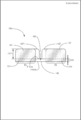
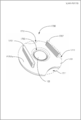
- FIG. 2 It is a perspective view which shows the cell holding
- FIG. 1 It is a figure which shows the prior art regarding a cell holding
- the cell holding and transporting apparatus will be described using a cell holding and transporting apparatus 100 that is an embodiment.
- the cell holding and transporting device 100 is a device for culturing cells in a well medium of a 96-well multiwell plate. The cells cultured in the well are used for predetermined experiments and examinations.
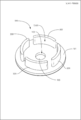
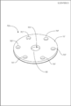
- FIG. 1 is a perspective view of the cell holding and transporting device 100
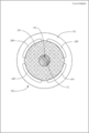
- FIG. 2 is a plan view of the cell holding and transporting device 100
- FIG. 3 is an X1-X1 cross section of FIG.
- the cell holding and transporting device 100 includes a base 101, a through hole 103, a cell scaffold 105, and an operation unit 107.
- the base 101 has a flat disk shape.
- the base 101 has an upper surface P101a and a lower surface P101b.
- the base 101 is made of a predetermined resin material having a specific gravity greater than that of the culture medium, for example, polycarbonate.
- the specific gravity of the cell holding and conveying apparatus 100 with respect to the medium and the buoyancy generated in the cell holding and conveying apparatus 100 with respect to the medium are comprehensively determined.
- the specific gravity of the base 101 and the like is determined, for example, a specific gravity of 1.05 to 1.1 or more.
- the base 101 has a diameter R101 (see FIG. 2) of about 6 mm and a thickness L101h (see FIG. 3) of about 0.5 mm. It is.
- the through-hole 103 is formed to penetrate the base 101 from the upper surface P101a to the lower surface P101b of the base 101.
- the through hole 103 has a cylindrical shape and is formed concentrically with the base 101.
- the diameter of the through hole 103 is about 1 mm.
- the cell scaffold 105 is formed of a fiber sheet made of a polymer material.
- the polymer material may be any material that does not exhibit cytotoxicity when cultured in a state where it is in contact with cells.
- a biodegradable or non-biodegradable polymer material can be used.
- biodegradable polymer materials include polylactic acid and polyglycolic acid copolymer (PLGA), polyglycolic acid (PGA), polybutyric acid (PLA), polyvinyl alcohol (PVA), and polyethylene glycol (PEG). , Polyethylene vinyl acetate (PEVA), polyethylene oxide (PEO), and the like, but are not limited thereto.
- PLGA is a highly safe material that is known to be hydrolyzed in vivo to become lactic acid and glycolic acid originally present in the body, and further decomposed into water and carbon dioxide and discharged outside the body. Are particularly preferably used. PLGA can adjust the biodegradation rate by changing the combination ratio of PLA (polylactic acid) and PGA (polyglycolic acid).
- Non-biodegradable polymer materials include, for example, polystyrene (PS), polycarbonate (PC), polymethyl methacrylate (PMMA), polyvinyl chloride, polyethylene terephthalate (PET), polyamide (PA), and polymethylglutarimide ( PMGI ) And the like, but is not limited thereto.
- PS polystyrene
- PC polycarbonate
- PMMA polymethyl methacrylate
- PET polyethylene terephthalate
- PA polyamide
- PMGI polymethylglutarimide
- PS polystyrene
- the cell scaffold 105 has a thin disk shape and is disposed along the lower surface P101b of the base 101.
- the cell scaffold 105 is disposed on the lower surface P101b of the base 101 by applying a predetermined adhesive to a predetermined adhesive region RA on the lower surface P101b of the base 101 and then bonding them together.
- the adhesive is applied to the lower surface P101b of the base 101 so as not to protrude from the through hole 103 when the cell scaffold 105 is disposed on the lower surface P101b of the base 101.
- the adhesive is absorbed into the gap between the cell scaffolds 105 made of fiber sheets and integrated with the cell scaffolds 105 at the stage where the cell scaffolds 105 are pressure-bonded to the lower surface P101b of the base 101.
- an adhesive for example, KE45 is used.
- a predetermined biological material for example, myocardium or nerve cell
- the biological material refers to 1: 1 or more cells or cell types, 2: 1 or more tissues, or tissue types, 3: organs, or parts thereof.
- the cells include muscle cells such as cardiomyocytes and smooth muscle cells, liver cells that are liver parenchymal cells, Kupffer cells, endothelial cells such as vascular endothelial cells and corneal endothelial cells, fibroblasts, osteoblasts, and crushing cells.
- Epithelial cells such as bone cells, periodontal ligament cells, epidermal keratinocytes, tracheal epithelial cells, gastrointestinal epithelial cells, cervical epithelial cells, corneal epithelial cells, mammary cells, pericytes, kidney cells, knees
- Examples include Langerhans islet cells, nerve cells such as peripheral nerve cells and optic nerve cells, chondrocytes, and bone cells.
- Examples of cardiomyocytes include cells derived from pluripotent stem cells such as ES cells or iPS cells.
- nerve cells include peripheral nerve cells and optic nerve cells.
- the operation unit 107 is formed so as to protrude from the upper surface P101a (see FIG. 3) of the base 101, as shown in FIG.
- a plurality of operation units 107 are formed radially on the upper surface P101a of the base 101 with the through hole 103 as the center.
- the operation units 107 are arranged in the shape of the upper surface P101a of the base 101 so that the angle between the adjacent operation units 107 is 60 degrees.
- Each operation unit 107 has an upper surface arc shape, and has a rectangular shape with a semicircular direction in a short direction in a cross section along the upper surface P101a of the base 101.
- the operation unit 107 is formed integrally with the base 101 from a predetermined resin material, for example, polycarbonate.
- Each operation unit 107 has a length L107a (see FIG. 2) in the longitudinal direction of about 2.5 mm, a length L107b in the short direction (see FIG. 2) of about 0.5 mm, and a height L107h (see FIG. 3). Reference) is about 1.3 mm.
- the cell holding and transporting device 100 When the cell holding and transporting device 100 is arranged in the well W1 by forming a plurality of operation units 107 in a radial manner, regardless of the positional relationship between the user and the operation unit 107, the user can change the angle of the wrist. It is possible to easily hold and operate the operation unit 107 with tweezers or the like simply by adjusting. By forming six operation units 107, the user can easily operate the operation unit 107.
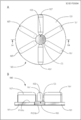
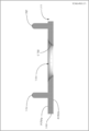
- FIG. 4 A is a plan view of the cell holding and transporting device 100 in which the cell suspension CS is stored, and B is a cross section taken along the line X4-X4 of FIG. 4A.
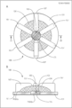
- FIG. 5 A is a plan view of the cell holding and transporting apparatus 100 in which the medium is stored, and B is a cross section taken along the line X5-X5 in FIG. 5A.
- a cell suspension is stored in the through-hole 103, and after several hours to about 1 day, the cells are fixed and held on the cell scaffold 105, and then using a pipette or the like.
- the medium is stored on the upper surface P101a of the base 101 (see FIG. 5B above). That is, a part of the space on the upper surface P101a of the base 101 functions as a culture medium storage space for storing the culture medium, and a part of the upper surface P101a of the base 101 functions as a culture medium storage space forming part.
- the medium can be stored in a convex shape in the upper surface P101a of the base 101 by the surface tension of the medium to be added.
- the base 101 is formed of a hydrophobic material, the medium can be more stably stored in a convex shape in the upper surface P101a of the base 101.
- a fresh medium can be provided to the cells being held, so that the cells can be stably cultured for a longer period of time.
- the operation unit 107 When operating the cell holding and conveying apparatus 100, the operation unit 107 is held by a holder such as tweezers. Thereby, the cell holding
- the operation holding unit 107 can be used to hold the cell holding and transporting device 100. Easy to operate.
- the cell holding and conveying apparatus 100 can be easily operated by holding the base 101 with a holder.
- the operation part 107 protruding from the medium can be held by the holder to prevent the medium from flowing out.
- the cell holding and transporting device 100 is held by the operation unit 107 with a holding tool. While being taken out from the well W1, it can be easily moved onto, for example, an electrode of a MEA (Multi-Electrode Array) probe to measure the electrical characteristics of the cells.
- MEA Multi-Electrode Array
- Example 1 the culture medium was disposed on the upper surface P101a of the base 101 using the surface tension of the culture medium and the hydrophobicity of the base 101 and the operation unit 107.
- the cell holding and transporting device 200 as an embodiment of the cell holding and transporting device according to the present invention has a medium storage space forming part 209 that forms a medium storage space S209 for storing a medium on the through hole 103.
- the medium can be easily arranged on the upper surface P101a of the base 101.
- the same components as those in the first embodiment are denoted by the same reference numerals, and detailed description thereof is omitted.
- FIG. 7 shows a perspective view of the cell holding and transporting apparatus 200.
- the cell holding and transporting device 200 has a base 101, a through-hole 103, a cell scaffold 105, and a medium storage space forming part 209.
- the medium storage space forming part 209 is formed so as to protrude from the upper surface P101a (see FIG. 3) of the base part 101.
- the culture medium storage space forming part 209 is formed in a cylindrical shape on the upper surface P101a of the base 101 with the through hole 103 as the center.
- the culture medium storage space forming part 209 is formed integrally with the base 101 by a predetermined resin material, like the base 101.
- the culture medium storage space S209 that stores the culture medium on the through hole 103 can be formed.
- the size of the medium storage space forming part 209 is such that the inner diameter is about 4.4 mm, the outer diameter is about 5.4 mm, and the height is high in the cell holding and transporting device 200 corresponding to the well W1 of the 96-well multiwell plate. About 1.3 mm.
- the culture medium storage space forming part 209 is formed so as to protrude from the upper surface P101a of the base part 101, it also functions as an operation part.
- FIG. 7 shows a perspective view of the cell holding and conveying device 200 in which the cell suspension CS is stored.
- a cell suspension is stored in the through-hole 103, and after several hours to about a day, the cells are fixed and held on the cell scaffold 105, and then, on the upper surface P101a of the base 101 using a pipette or the like.
- the culture medium is stored in the culture medium storage space S209 formed by the culture medium storage space forming unit 209 located in the position.
- the medium is stored in a convex shape in the upper surface P101a of the base 101 due to the surface tension of the culture medium to be added and / or the hydrophobicity of the base 101 (FIG. 5B). In some cases, it is difficult to stably store the culture medium. However, in the cell holding and transporting device 200, since the culture medium storage space S209 is formed by the culture medium storage space forming unit 209, the culture medium storage space S209 is stably formed. The culture medium can be stored in the culture medium storage space S209 on the upper surface P101a.
- a fresh medium can be provided to the retained cells by stably storing the medium on the base 101, so that the cells can be stably cultured for a longer period of time. can do.
- the cell holding and conveying apparatus 200 in Example 2 described above had one medium storage space forming part 209 formed in a cylindrical shape.
- the cell holding and transporting apparatus 300 which is an embodiment of the cell holding and transporting apparatus according to the present invention has a plurality of medium storage space forming portions 209.
- components similar to those in the first and second embodiments are denoted by the same reference numerals, and detailed description thereof is omitted.
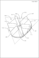
- FIG. 8 shows a perspective view of the cell holding and transporting apparatus 300.
- the cell holding and transporting device 300 includes a base 101, a through-hole 103, a cell scaffold 105, and a medium storage space forming unit 309.
- a plurality of medium storage space forming portions 309 are formed so as to protrude from the upper surface P101a of the base portion 101 (see FIG. 3).
- the culture medium storage space forming unit 309 is formed independently of the other adjacent culture medium storage space forming unit 309, and a predetermined space is disposed between them.
- the plurality of medium storage space forming portions 309 form a cylindrical shape centered on the through hole 103 on the upper surface P101a of the base 101.
- the culture medium storage space s309 is formed inside the culture medium storage space formation part 309 by the plurality of culture medium storage space formation parts 309 arranged along the cylindrical shape.
- the culture medium storage space forming part 309 is formed integrally with the base part 101 by polycarbonate, like the base part 101.
- the size of the medium storage space forming unit 309 is the same as that of the medium storage space forming unit 209 of the second embodiment.
- the culture medium storage space forming part 309 is formed so as to protrude from the upper surface P101a of the base part 101, it also functions as an operation part.
- FIG. 9 shows a plan view of the cell suspension CS and the cell holding and transporting device 300 in which the medium is stored.
- the cell holding and transporting device 300 is the same as the cell holding and transporting device 100 until cells are cultured and held in the cell scaffold 105. Further, in the cell holding and transporting device 300, the same operation as that of the cell holding and transporting device 200 is performed until the medium is stored in the medium storing space S309 formed by the medium storing space forming unit 309.
- a medium storage space S309 is formed by the plurality of separated medium storage space forming units 309. That is, in the medium storage space S309, an opening leading to the outside of the medium storage space forming unit 309 is formed. As shown in FIG. 9, the surface tension of the medium to be added and / or the base 101 is provided. Due to the hydrophobicity, the medium can be stably stored in the medium storage space S309 (see FIG. 8 above).
- a fresh medium can be provided to the retained cells by stably storing the medium on the base 101, so that the cells can be stably cultured for a longer period of time. can do.
- Example 1 when the cell holding and transporting device 100 is disposed in the well W1, it is necessary to immerse the cell holding and transporting device 100 in the medium stored in the well W1. At this time, if there is not much difference between the inner diameter of the well W1 and the diameter R101 (see FIG. 2) of the base 101 of the cell holding and transporting device 100, a medium is present between the side surface of the well W1 and the cell holding and transporting device 100. Air that has entered and has entered under the cell holding and conveying device 100 may not be able to escape well from the side surface of the well W1 and the cell holding and conveying device 100.
- a cell holding and transporting device 400 that is an embodiment of the cell holding and transporting device according to the present invention has a base 101 and an air vent 413 that penetrates the cell scaffold 105 located at the bottom of the base 101, and holds the cell.
- the air that has entered the lower part of the conveying device 400 can be easily discharged to the outside.
- the same components as those in the first embodiment are denoted by the same reference numerals, and detailed description thereof is omitted.
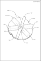
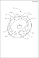
- FIG. 10 shows a perspective view of the cell holding and transporting device 400.
- the cell holding and transporting device 400 includes a base 101, a through-hole 103, a cell scaffold 105, an operation unit 107, and an air vent 413.
- the air vent 413 is a rectangular cutout formed from the outer periphery of the base 101 toward the inside, and is formed so as to penetrate the base 101 and the cell scaffold 105. Thereby, the air that has entered the lower part of the cell holding and transporting device 400 from between the base 101 and the side surface of the well W1 can be easily discharged to the outside.
- the method of using the cell holding and transporting device 400 is the same as that of the cell holding and transporting device 100. However, the cell holding and transporting device 400 is immersed in the medium of the well W1 while confirming that air is released from the air vent 413.
- the cell holding and transporting device 1700 is easier to cultivate cells, easier to use, and has a simple structure.
- the same components as those of the first embodiment are denoted by the same reference numerals, and detailed description thereof is omitted.
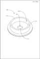
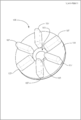
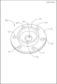
- FIG. 20 is a perspective view of the cell holding and transporting device 1700 from obliquely above.
- the cell holding and transporting device 1700 has a base 1701, a through hole 1703, a cell culture holding member 105, an operation unit 1707, and an air vent 1711.
- the base 1701 has a thin disk shape.
- the base 1701 is made of polycarbonate, for example.
- the through hole 1703 is formed at the center of the base 1701.
- the base 1701 has an upper surface P1701a and a lower surface P1701b (see FIG. 21).
- the through-hole 1703 is formed so as to penetrate the base 1701 from the upper surface P1701a to the lower surface P1701b of the base 1701.
- the through hole 1703 has a truncated cone shape that narrows from the upper surface P1701a on which the operation unit 1707 is formed toward the lower surface P1701b.
- the through hole 1703 has an inclined portion S1703 at a predetermined distance from the lower surface P1701b of the base portion 1701 toward the upper surface P1701a.
- the inclined portion S1703 is formed as a surface inclined by a predetermined angle from the axial direction.
- the axial section of the inclined portion S1703 is an inclined straight line.
- the operation unit 1707 is formed so as to protrude from the upper surface P1701a of the base 1701.
- the operation portion 1707 is formed on the upper surface P1701a of the base portion 1701 in parallel with the through hole 1703 therebetween. Accordingly, since the operation portion 1707 can be formed at a distance from the through-hole 1703, when the cells are cultured, the cell culture solution stored in the through-hole 1703 exceeds its surface tension, and the through-hole 1703 is formed. Can be prevented from flowing out.
- the cell holding and conveying device 1700 can be easily operated by being easily held by tweezers.
- the operation unit 1707 is formed integrally with the base 1701 from a predetermined resin material, for example, polycarbonate, like the base 1701. By disposing the operation unit 1707, the operation unit 1707 can be held with tweezers or the like, so that the user can easily operate the cell holding and transporting device 1700.
- the air vent part 1711 is formed as a region where a part of the outer peripheral part of the base part 1701 is cut off.
- the thin cell culture holding member 1701 located below the base 1701 is also formed in the same shape as the base 1701.
- the method for using the cell holding and transporting device 1700 is the same as that of the cell holding and transporting device 100 to the cell holding and transporting device 400.
- a method of using the cell holding and transporting device 1700 when measuring cell characteristics will be described by taking an example of measuring an extracellular potential generated by cellular activity of cardiomyocytes formed in the cell holding and transporting device 1700.
- FIG. 21A is a plan view of the MEA probe P
- FIG. 22B is an X4-X4 cross-sectional view of the MEA probe P shown in FIG. 22A.
- the MEA probe P has a substrate portion PB and a molten wall portion PW.
- the substrate part PB has a thin plate shape.
- the molten wall portion PW is formed on the substrate portion PB.
- the molten wall portion PW has a cylindrical shape with one end released, stores a predetermined medium therein, and forms a cell arrangement space PS for arranging cells to be measured.
- the MEA probe P has a measurement electrode E1 and a reference electrode E2.
- the measurement electrode E1 is formed along the substrate portion PB in the approximate center of the molten wall portion PW.
- the measurement electrodes E1 are arranged in a 4 ⁇ 4 matrix.
- a predetermined number of reference electrodes E2 are arranged around the measurement electrode E1.
- the MEA probe P measures the extracellular potential due to cell activity based on the potential difference between the measurement electrode E1 and the reference electrode E2.
- a lead line (dotted line in the figure) is arranged from each of the measurement electrode E1 and the reference electrode E2.
- the cell holding and conveying device 1700 in which cardiomyocytes are cultured is arranged in the cell arrangement space PS.
- the cell holding and conveying device 1700 is arranged on the measurement electrode E1 of the MEA probe P so that the region corresponding to the through hole 1703 in the cell culture holding member 105 is located.
- the extracellular potential due to the cellular activity of the cardiomyocytes cultured in the cell holding and transporting device 1700 is measured using the MEA probe P.
- the oriented fiber sheet of the cell culture holding member 105 was seeded with human iPS cell-derived cardiomyocytes and cultured for 7 days in an environment of 5% CO 2 and 37 ° C.
- the pitch of the fiber sheet is the distance between the cores of adjacent fibers among the fibers constituting the fiber sheet.
- the drug responsiveness to the cultured cardiomyocytes can be measured via the extracellular potential.
- dofetilide atrial fibrillation drug, Sigma
- a cell holding and conveying device 1700 in which predetermined cardiomyocytes were cultured was placed in the cell placement space PS of the MEA probe P filled with a predetermined medium. Then, the extracellular potential was measured when only DMSO (Dimethyl ⁇ Sulfoxide), dofetilide: 0.0003 ⁇ M, dofetilide: 0.001 ⁇ M, dofetilide: 0.003 ⁇ M were used as the conditions of the drug to be administered. The result is shown in FIG.
- DMSO Dimethyl ⁇ Sulfoxide
- the first peak potential and the second peak potential generated by the heartbeat change depending on the condition of the drug. Specifically, it can be seen that as the concentration of the drug dofetilide increases, the time required from the first peak potential to the second peak potential appears as a longer time. That is, it can be confirmed that the time between the first peak and the second peak is extended depending on the concentration. Thus, using the cell holding and conveying device 1700, drug responsiveness as a cell characteristic can be confirmed. [Other Embodiments]
- the through-hole 103 has a cylindrical shape that penetrates from the upper surface P101a to the lower surface P101b of the base 101, but may have a shape that penetrates from the upper surface P101a to the lower surface P101b.
- the through-hole 503 may have a truncated cone shape that narrows from the upper surface P101a on which the operation unit 107 is formed toward the lower surface P101b (see FIG. 3 above). Good.
- Shape of the operation unit 107 In the cell holding and transporting device 100 of Example 1 described above, a plurality of operation units 107 are formed in a radial manner, as long as the operation unit 107 protrudes from the upper surface P101a side of the base 101.
- the present invention is not limited to the examples.
- a plurality of operation portions 607 having a columnar protruding shape may be formed as in the cell holding and conveying device 600 shown in FIG.
- the present invention is not limited to the examples as long as it can be sandwiched by a predetermined holder and the cell holding and transporting apparatus can be operated.
- the cell holding and transporting apparatus 700 shown in FIG. 13 for example, an operation part 707 having a through hole formed in a concave shape from the upper surface P ⁇ b> 101 a (refer to FIG. 3) of the base 101 may be formed.
- a plurality of notched operation portions 807 may be formed on the outer peripheral surface of the base portion 101, and the shape of the base portion 101 may be a gear shape.
- the medium storage space forming unit 209 is an integrated type that also has the function of an operation unit.
- the operation unit 907 that protrudes from the upper surface P101a of the base 101 may be arranged in the cell holding and transport device 300 of the third embodiment.
- an operation unit 1007 formed in a concave shape from the upper surface P101a of the base 101 may be arranged in the cell holding and transporting apparatus 200 of the second embodiment. The same applies to Example 3 and the like.
- Air venting part 413 In the cell holding and transporting device 400 of Example 4 described above, the air venting part 413 is formed as a rectangular cutout formed from the outer periphery of the base 101 toward the inside.
- the present invention is not limited to the example as long as the air that has entered the lower part of the apparatus can be discharged.
- a part of the outer periphery of the base 101 and an air vent 1113 obtained by excising the cell scaffold 105 located thereunder may be formed.
- the excision of the base 101, the cell scaffold 105, and in some cases the operation unit 107 is not limited to the excision along the triangular shape as shown in FIG. 17, but may be an excision along a polygonal shape such as a hexagonal shape. It may be a resection of a desired location.
- Cells to be cultured In Examples 1 to 4 described above, cardiomyocytes and nerve cells were shown as cells to be cultured, but are not limited to those exemplified. For example, it may be a pluripotent stem cell-derived nerve cell. Examples of pluripotent stem cells include embryonic stem cells (ES cells) and iPS cells.
- ES cells embryonic stem cells
- iPS cells iPS cells
- the cell holding / transporting device 100 is disposed in the well W1 of the 96-well multi-well plate.
- the container is not limited to the examples as long as it is a container that can culture cells.
- it may be a culture container such as a culture dish that is a single well.
- the base 101 and the operation unit 107 are formed as a single unit. You may make it join both using an adhesive member. The same applies to the other embodiments except the first embodiment.
- Placement in the well W1 In the above-described first embodiment, when the cell holding and transporting device 100 is placed in the well W1, the cell holding and transporting device 100 is immersed in the medium stored in the well W1.
- the method is not limited to the illustrated example as long as the cell holding and transporting device 100 can be disposed in the well W1.
- the culture medium may be poured from the space between the cell holding / transporting device 100 and the side wall of the well W1.
- Example 5 the drug responsiveness as the cell characteristics is measured as an example of use of the cell holding and transporting device 1700, but the cell characteristics are not limited to the exemplified cell characteristics.
- patch clamps, imaging, biomarkers, and the like may be used.
- dofetilide was used as a drug used for measuring drug responsiveness, other drugs may be used. The same applies to the other embodiments.
- Base 101 In the above-described first embodiment, the base 101 has a flat plate shape, but is not limited to the illustrated one as long as it has an upper surface and a lower surface. For example, it may be a cylindrical shape with its upper end closed or a columnar shape.
- the base 101 may not be formed of a resin material, but may be formed of a predetermined metal material, particularly a metal material that has low or no biotoxicity. Thereby, the weight of the cell holding and conveying apparatus 100 can be adjusted. Further, the base 101 is formed by combining a resin material and a metal material, for example, by combining a resin material and a metal material of the same shape, or by using a part of the resin material as a metal material. May be. Further, the cell holding and transporting device 100 may be generated by forming different members with different molding materials, such as using a resin material base 101 and a metal material operation unit 107. Furthermore, a part may be formed of the same material such as resins, and the integrated base 101, the operation unit 107, and the like may be formed. The same applies to the other embodiments.
- the cell holding and transporting apparatus according to the present invention can be used for, for example, a drug efficacy test using a 96-well multiwell plate.
Landscapes
- Health & Medical Sciences (AREA)
- Life Sciences & Earth Sciences (AREA)
- Wood Science & Technology (AREA)
- Organic Chemistry (AREA)
- Engineering & Computer Science (AREA)
- Bioinformatics & Cheminformatics (AREA)
- Chemical & Material Sciences (AREA)
- Zoology (AREA)
- Biomedical Technology (AREA)
- Sustainable Development (AREA)
- Microbiology (AREA)
- Biotechnology (AREA)
- Biochemistry (AREA)
- General Engineering & Computer Science (AREA)
- General Health & Medical Sciences (AREA)
- Genetics & Genomics (AREA)
- Immunology (AREA)
- Clinical Laboratory Science (AREA)
- Molecular Biology (AREA)
- Apparatus Associated With Microorganisms And Enzymes (AREA)
- Micro-Organisms Or Cultivation Processes Thereof (AREA)
Abstract
[Problème] Fournir un dispositif de retenue et de transport de cellules pouvant retenir des cellules cultivées et les déplacer dans cet état. [Solution] Le dispositif de retenue et de transport de cellules (100) de l'invention comprend une partie de base (101), un trou traversant (103), un échafaudage cellulaire (105), et des parties fonctionnelles (107). L'échafaudage cellulaire (105) retient des cellules prédéterminées, par exemple des cellules de muscle cardiaque ou des cellules neuronales. Une pipette ou similaire est utilisée pendant que les cellules prédéterminées sont retenues sur l'échafaudage cellulaire (105); et la culture s'effectue par dépôt d'une suspension cellulaire à travers le trou traversant (103) et sur l'échafaudage cellulaire (105) exposé à partir du trou traversant (103). Les parties fonctionnelles sont formées saillantes depuis une surface supérieure (P101a) de la partie de base (101). Les parties fonctionnelles (107) sont disposées en groupes pour formation, selon une configuration radiale centrée, sur le trou traversant (103), sur la surface supérieure (P101a) de la partie de base (101). Les parties fonctionnelles peuvent être retenues à l'aide d'un outil de retenue, tel que des brucelles, et le dispositif de retenue et de transport de cellules peut être mis en oeuvre facilement par formation des parties fonctionnelles (107).
Priority Applications (3)
| Application Number | Priority Date | Filing Date | Title |
|---|---|---|---|
| EP19761426.6A EP3760701A4 (fr) | 2018-02-28 | 2019-02-26 | Dispositif de retenue et de transport de cellules |
| JP2020503533A JP7441521B2 (ja) | 2018-02-28 | 2019-02-26 | 細胞保持運搬装置 |
| US16/975,659 US20200407674A1 (en) | 2018-02-28 | 2019-02-26 | Cell holding and transporting device |
Applications Claiming Priority (2)
| Application Number | Priority Date | Filing Date | Title |
|---|---|---|---|
| JP2018-035458 | 2018-02-28 | ||
| JP2018035458 | 2018-02-28 |
Publications (1)
| Publication Number | Publication Date |
|---|---|
| WO2019167960A1 true WO2019167960A1 (fr) | 2019-09-06 |
Family
ID=67805006
Family Applications (1)
| Application Number | Title | Priority Date | Filing Date |
|---|---|---|---|
| PCT/JP2019/007361 Ceased WO2019167960A1 (fr) | 2018-02-28 | 2019-02-26 | Dispositif de retenue et de transport de cellules |
Country Status (4)
| Country | Link |
|---|---|
| US (1) | US20200407674A1 (fr) |
| EP (1) | EP3760701A4 (fr) |
| JP (1) | JP7441521B2 (fr) |
| WO (1) | WO2019167960A1 (fr) |
Cited By (4)
| Publication number | Priority date | Publication date | Assignee | Title |
|---|---|---|---|---|
| WO2020085423A1 (fr) * | 2018-10-25 | 2020-04-30 | 株式会社幹細胞&デバイス研究所 | Dispositif de maintien de cellule |
| WO2021006286A1 (fr) * | 2019-07-10 | 2021-01-14 | 株式会社幹細胞&デバイス研究所 | Procédé de calcul de caractéristique de mouvement de contraction-relaxation d'ensemble de cellules |
| JP2022147701A (ja) * | 2021-03-23 | 2022-10-06 | 日本毛織株式会社 | 神経細胞ネットワーク、その製造方法、その作製キット、並びに神経細胞の評価方法及び化合物の評価方法 |
| JP2023549636A (ja) * | 2020-11-25 | 2023-11-29 | コーニンクレッカ フィリップス エヌ ヴェ | 細胞もしくは組織の培養、またはインビトロ筋肉組織における試験のための装置 |
Citations (15)
| Publication number | Priority date | Publication date | Assignee | Title |
|---|---|---|---|---|
| JPH0615499U (ja) * | 1992-08-04 | 1994-03-01 | 住友ベークライト株式会社 | 培養用小片 |
| JPH06189742A (ja) * | 1992-09-28 | 1994-07-12 | Becton Dickinson & Co | 細胞培養挿入体 |
| JPH06237758A (ja) * | 1993-01-13 | 1994-08-30 | Becton Dickinson & Co | 培養容器 |
| JPH0775553A (ja) * | 1993-08-12 | 1995-03-20 | Becton Dickinson & Co | 生体外で組織培養物を成長させる装置 |
| JP2006271369A (ja) * | 2005-03-02 | 2006-10-12 | Nippon Sheet Glass Co Ltd | 生化学用容器 |
| WO2006123570A1 (fr) * | 2005-05-17 | 2006-11-23 | Kuraray Co., Ltd. | Recipient de culture cellulaire |
| JP2007167002A (ja) * | 2005-12-22 | 2007-07-05 | Asahi Techno Glass Corp | 細胞培養用カセット、細胞培養用カセット着脱用治具及び細胞培養装置 |
| JP2009022247A (ja) * | 2007-07-23 | 2009-02-05 | Toshiba Corp | 培養容器及び培養組織回収方法 |
| JP2010063411A (ja) * | 2008-09-11 | 2010-03-25 | Teijin Ltd | 細胞培養用基材 |
| WO2016060260A1 (fr) * | 2014-10-16 | 2016-04-21 | 国立大学法人京都大学 | Fragment de tissu |
| JP2016067322A (ja) | 2014-09-30 | 2016-05-09 | 富士フイルム株式会社 | プラスチック製容器 |
| JP2016093149A (ja) * | 2014-11-14 | 2016-05-26 | 真志 池内 | 細胞培養装置および細胞培養方法 |
| WO2018042532A1 (fr) * | 2016-08-31 | 2018-03-08 | 株式会社メニコン | Récipient de culture cellulaire |
| WO2019073522A1 (fr) * | 2017-10-10 | 2019-04-18 | 株式会社サイフューズ | Plateau de cellules et élément d'ensemble de tissu non tissé |
| WO2019087991A1 (fr) * | 2017-10-30 | 2019-05-09 | 株式会社幹細胞&デバイス研究所 | Dispositif d'aide à la mesure du potentiel extracellulaire |
Family Cites Families (5)
| Publication number | Priority date | Publication date | Assignee | Title |
|---|---|---|---|---|
| CH586282A5 (fr) * | 1974-10-22 | 1977-03-31 | Wild Dr & Co Ag | |
| CA2055966C (fr) * | 1990-12-19 | 1995-08-01 | Oresta Natalia Fedun | Dispositif d'insertion de culture cellulaire |
| US5635396A (en) * | 1995-08-30 | 1997-06-03 | Becton, Dickinson And Company | Coverslip holder |
| US20040091397A1 (en) * | 2002-11-07 | 2004-05-13 | Corning Incorporated | Multiwell insert device that enables label free detection of cells and other objects |
| JP6480285B2 (ja) * | 2015-08-04 | 2019-03-06 | 豊田合成株式会社 | 細胞培養器具およびその製造方法 |
-
2019
- 2019-02-26 EP EP19761426.6A patent/EP3760701A4/fr not_active Withdrawn
- 2019-02-26 US US16/975,659 patent/US20200407674A1/en not_active Abandoned
- 2019-02-26 JP JP2020503533A patent/JP7441521B2/ja active Active
- 2019-02-26 WO PCT/JP2019/007361 patent/WO2019167960A1/fr not_active Ceased
Patent Citations (15)
| Publication number | Priority date | Publication date | Assignee | Title |
|---|---|---|---|---|
| JPH0615499U (ja) * | 1992-08-04 | 1994-03-01 | 住友ベークライト株式会社 | 培養用小片 |
| JPH06189742A (ja) * | 1992-09-28 | 1994-07-12 | Becton Dickinson & Co | 細胞培養挿入体 |
| JPH06237758A (ja) * | 1993-01-13 | 1994-08-30 | Becton Dickinson & Co | 培養容器 |
| JPH0775553A (ja) * | 1993-08-12 | 1995-03-20 | Becton Dickinson & Co | 生体外で組織培養物を成長させる装置 |
| JP2006271369A (ja) * | 2005-03-02 | 2006-10-12 | Nippon Sheet Glass Co Ltd | 生化学用容器 |
| WO2006123570A1 (fr) * | 2005-05-17 | 2006-11-23 | Kuraray Co., Ltd. | Recipient de culture cellulaire |
| JP2007167002A (ja) * | 2005-12-22 | 2007-07-05 | Asahi Techno Glass Corp | 細胞培養用カセット、細胞培養用カセット着脱用治具及び細胞培養装置 |
| JP2009022247A (ja) * | 2007-07-23 | 2009-02-05 | Toshiba Corp | 培養容器及び培養組織回収方法 |
| JP2010063411A (ja) * | 2008-09-11 | 2010-03-25 | Teijin Ltd | 細胞培養用基材 |
| JP2016067322A (ja) | 2014-09-30 | 2016-05-09 | 富士フイルム株式会社 | プラスチック製容器 |
| WO2016060260A1 (fr) * | 2014-10-16 | 2016-04-21 | 国立大学法人京都大学 | Fragment de tissu |
| JP2016093149A (ja) * | 2014-11-14 | 2016-05-26 | 真志 池内 | 細胞培養装置および細胞培養方法 |
| WO2018042532A1 (fr) * | 2016-08-31 | 2018-03-08 | 株式会社メニコン | Récipient de culture cellulaire |
| WO2019073522A1 (fr) * | 2017-10-10 | 2019-04-18 | 株式会社サイフューズ | Plateau de cellules et élément d'ensemble de tissu non tissé |
| WO2019087991A1 (fr) * | 2017-10-30 | 2019-05-09 | 株式会社幹細胞&デバイス研究所 | Dispositif d'aide à la mesure du potentiel extracellulaire |
Non-Patent Citations (2)
| Title |
|---|
| DERMUTZ, HARALD ET AL.: "Paper-based patterned 3D neural cultures as a tool to study network activity on multielectrode arrays", RSC ADVANCES, vol. 7, 11 August 2017 (2017-08-11), pages 39359 - 39371, XP055610324, doi:10.1039/C7RA00971B * |
| See also references of EP3760701A4 |
Cited By (5)
| Publication number | Priority date | Publication date | Assignee | Title |
|---|---|---|---|---|
| WO2020085423A1 (fr) * | 2018-10-25 | 2020-04-30 | 株式会社幹細胞&デバイス研究所 | Dispositif de maintien de cellule |
| WO2021006286A1 (fr) * | 2019-07-10 | 2021-01-14 | 株式会社幹細胞&デバイス研究所 | Procédé de calcul de caractéristique de mouvement de contraction-relaxation d'ensemble de cellules |
| JP2023549636A (ja) * | 2020-11-25 | 2023-11-29 | コーニンクレッカ フィリップス エヌ ヴェ | 細胞もしくは組織の培養、またはインビトロ筋肉組織における試験のための装置 |
| JP2022147701A (ja) * | 2021-03-23 | 2022-10-06 | 日本毛織株式会社 | 神経細胞ネットワーク、その製造方法、その作製キット、並びに神経細胞の評価方法及び化合物の評価方法 |
| JP7687607B2 (ja) | 2021-03-23 | 2025-06-03 | 日本毛織株式会社 | 神経細胞ネットワーク、その製造方法、その作製キット、並びに神経細胞の評価方法及び化合物の評価方法 |
Also Published As
| Publication number | Publication date |
|---|---|
| JP7441521B2 (ja) | 2024-03-01 |
| EP3760701A4 (fr) | 2021-12-08 |
| US20200407674A1 (en) | 2020-12-31 |
| EP3760701A1 (fr) | 2021-01-06 |
| JPWO2019167960A1 (ja) | 2021-02-12 |
Similar Documents
| Publication | Publication Date | Title |
|---|---|---|
| JP7441521B2 (ja) | 細胞保持運搬装置 | |
| US10034738B2 (en) | Cardiac tissue constructs and methods of fabrication thereof | |
| Ng et al. | based cell culture platform and its emerging biomedical applications | |
| Fang et al. | Rapid generation of multiplexed cell cocultures using acoustic droplet ejection followed by aqueous two-phase exclusion patterning | |
| CN102947710B (zh) | 悬滴装置、系统和/或方法 | |
| JP6767375B2 (ja) | 細胞培養容器 | |
| KR101190039B1 (ko) | 세포 배양 용기 | |
| JP6877540B2 (ja) | 細胞積層体の製造方法 | |
| US10513684B2 (en) | Manufacturing method and device for three-dimensional engineered tissue | |
| Chen et al. | Naked liquid marbles: a robust three-dimensional low-volume cell-culturing system | |
| Ueda et al. | Superhydrophilic–superhydrophobic patterned surfaces as high‐density cell microarrays: optimization of reverse transfection | |
| US20210371782A1 (en) | Methods for optical micropatterning of hydrogels and uses thereof | |
| CN101939416A (zh) | 细胞培养方法及筛选方法 | |
| Tröndle et al. | Bioprinting of high cell‐density constructs leads to controlled lumen formation with self‐assembly of endothelial cells | |
| Antanavičiūtė et al. | Femtosecond laser micro‐machined polyimide films for cell scaffold applications | |
| Soman et al. | Femtosecond laser-assisted optoporation for drug and gene delivery into single mammalian cells | |
| Sifringer et al. | Photopatterning of conductive hydrogels which exhibit tissue-like properties | |
| JP7278523B2 (ja) | 細胞培養容器 | |
| US20140178920A1 (en) | Solid support for endothelial cell growth | |
| Aitova et al. | Biomimetic cardiac tissue models for in vitro arrhythmia studies | |
| JP2021136996A (ja) | 細胞培養容器及び細胞チップ | |
| US20230235261A1 (en) | Droplet trapping structure array, method for spheroid transfer and formation of spheroid array using the same | |
| Joshi | Engineering Tunable Collagen Fiber Alignment Gradients to Quantify Contact Guidance Effects on Cell Migration | |
| Heidari et al. | A multi-layer, self-aligning hydrogel micro-molding process offering a fabrication route to perfusable 3D in-vitro microvasculature | |
| JP2015177755A (ja) | 細胞排除性を発現する溝構造 |
Legal Events
| Date | Code | Title | Description |
|---|---|---|---|
| 121 | Ep: the epo has been informed by wipo that ep was designated in this application |
Ref document number: 19761426 Country of ref document: EP Kind code of ref document: A1 |
|
| ENP | Entry into the national phase |
Ref document number: 2020503533 Country of ref document: JP Kind code of ref document: A |
|
| NENP | Non-entry into the national phase |
Ref country code: DE |
|
| ENP | Entry into the national phase |
Ref document number: 2019761426 Country of ref document: EP Effective date: 20200928 |