EP3760744A1 - Procédé de chargement de matières premières dans un haut fourneau - Google Patents
Procédé de chargement de matières premières dans un haut fourneau Download PDFInfo
- Publication number
- EP3760744A1 EP3760744A1 EP19776073.9A EP19776073A EP3760744A1 EP 3760744 A1 EP3760744 A1 EP 3760744A1 EP 19776073 A EP19776073 A EP 19776073A EP 3760744 A1 EP3760744 A1 EP 3760744A1
- Authority
- EP
- European Patent Office
- Prior art keywords
- ore
- charging
- furnace
- small
- charged
- Prior art date
- Legal status (The legal status is an assumption and is not a legal conclusion. Google has not performed a legal analysis and makes no representation as to the accuracy of the status listed.)
- Granted
Links
Images





Classifications
-
- C—CHEMISTRY; METALLURGY
- C21—METALLURGY OF IRON
- C21B—MANUFACTURE OF IRON OR STEEL
- C21B5/00—Making pig-iron in the blast furnace
- C21B5/008—Composition or distribution of the charge
-
- C—CHEMISTRY; METALLURGY
- C21—METALLURGY OF IRON
- C21B—MANUFACTURE OF IRON OR STEEL
- C21B7/00—Blast furnaces
- C21B7/18—Bell-and-hopper arrangements
- C21B7/20—Bell-and-hopper arrangements with appliances for distributing the burden
-
- C—CHEMISTRY; METALLURGY
- C21—METALLURGY OF IRON
- C21B—MANUFACTURE OF IRON OR STEEL
- C21B5/00—Making pig-iron in the blast furnace
-
- F—MECHANICAL ENGINEERING; LIGHTING; HEATING; WEAPONS; BLASTING
- F27—FURNACES; KILNS; OVENS; RETORTS
- F27B—FURNACES, KILNS, OVENS OR RETORTS IN GENERAL; OPEN SINTERING OR LIKE APPARATUS
- F27B1/00—Shaft or like vertical or substantially vertical furnaces
- F27B1/10—Details, accessories or equipment specially adapted for furnaces of these types
- F27B1/20—Arrangements of devices for charging
-
- F—MECHANICAL ENGINEERING; LIGHTING; HEATING; WEAPONS; BLASTING
- F27—FURNACES; KILNS; OVENS; RETORTS
- F27D—DETAILS OR ACCESSORIES OF FURNACES, KILNS, OVENS OR RETORTS, IN SO FAR AS THEY ARE OF KINDS OCCURRING IN MORE THAN ONE KIND OF FURNACE
- F27D3/00—Charging; Discharging; Manipulation of charge
- F27D3/10—Charging directly from hoppers or shoots
Definitions
- the present invention relates to a method for charging raw materials into a blast furnace that includes a bell-less-type charging device.
- Patent Literature 1 discloses a method for uniformly mixing coke with ore in a bell-less-type blast furnace. In the method, coke is charged into some of the ore hoppers, the some ore hoppers being downstream hoppers, to deposit the coke on ore on a conveyor, the resultant is then charged into a furnace top hopper, and the ore and the coke are then charged into the blast furnace via a rotating chute.
- Patent Literature 2 discloses a method for performing center charging of coke and mixed charging of ore and coke smoothly in a steady manner. In the method, ore and coke are separately stored in hoppers on the furnace top, and simultaneous mixed charging of the coke and the ore is performed.
- Patent Literature 3 discloses a method for charging raw materials.
- raw materials are supplied from an auxiliary supply passage to a raw material main supply passage that connects a blast furnace raw material storage hopper to a distribution chute.
- Patent Literature 3 discloses an embodiment in which an auxiliary raw material is sequentially mixed with a main raw material and supplied into the furnace in conjunction with the time at which the main raw material is charged.
- Patent Literature 4 discloses a method for charging raw materials into a blast furnace.
- a plurality of raw materials is simultaneously charged from a plurality of main hoppers.
- a pressure adjustment time is necessary for replacing the atmosphere within the main hoppers with an atmosphere corresponding to the blast furnace interior atmosphere. From the standpoint of maintaining a production volume, using a hopper exclusively for a small amount of raw material is not practical.
- Patent Literature 5 discloses a method in which a small-size second hopper for charging a small amount of raw material is provided in addition to ordinary hoppers (first hoppers), and a raw material is charged from the second hopper either during intervals between the operations of charging a main raw material from the first hoppers or simultaneously with the charging of the main raw material, depending on the type of the raw material.
- a pressure adjustment time is necessary for replacing the atmosphere within the hopper with an air atmosphere when raw materials are to be stored in the hopper and for replacing the atmosphere within the hopper with an atmosphere corresponding to the blast furnace interior atmosphere when the raw materials are to be discharged into the blast furnace. Accordingly, using a hopper exclusively for a small amount of raw material is not practical from the standpoint of maintaining a production volume. According to Patent Literature 5, the second hopper disclosed is provided to solve the problem, and a small amount of raw material can be charged independently, which enables effective use of a small amount of raw material.
- NPL 1 Shimizu et al., "A basic study of the control of a coke in deadman of a blast furnace", Tetsu-To-Hagane, The Iron and Steel Institute of Japan, 1987, vol. 73, S754
- An object of the present invention is to provide methods for charging raw materials into a blast furnace, the methods being designed to solve problems associated with the related art technologies, such as the problems described above. Specifically, for a blast furnace including a bell-less-type charging device and regarding the formation of a mixture layer of small-size coke and ore in the furnace, the methods promote the reduction reaction of the ore while preventing a particle size reduction of coke in deadman, thereby inhibiting deterioration of the gas permeability of the burden layer in the blast furnace and improving the reducibility thereof.
- a mixture layer of small-size coke and ore can be formed to have an appropriate state in a furnace, which makes it possible to inhibit a particle size reduction of coke in deadman and an associated deterioration of gas permeability in a furnace central portion while promoting the reduction reaction of ore and, therefore, improving reducibility.
- small-size coke is to be mixed with ore in a main hopper in advance and thereafter discharged into a blast furnace.
- a blast furnace In this case, at an initial stage of raw material charging, only ore is charged into the main hopper, and subsequently, raw materials including small-size coke are charged into the main hopper, to prevent the small-size coke from being discharged at an initial stage of discharging.
- the main hopper segregation occurs due to a difference in density between the ore and the small-size coke.
- the raw materials are discharged from the main hopper in a funnel flow
- the raw materials that are discharged has a small-size coke mixing ratio different from the small-size coke mixing ratio at the time when the small-size coke is charged into the main hopper. Consequently, controlling the small-size coke in a manner such that a preferred mixed state, such as that described above, is achieved is difficult.
- a bell-less charging device including a plurality of main hoppers and an auxiliary hopper at a furnace top portion is used.
- the auxiliary hopper has a smaller capacity than the main hoppers. Ore is charged into at least one of the plurality of main hoppers, and an amount of small-size coke for a plurality of charges is charged into the auxiliary hopper. An amount of the ore per charge is discharged in batches from the main hoppers, and an amount of the small-size coke per charge is discharged in batches from the auxiliary hopper.
- a ratio of mixing of the small-size coke can be varied by adjusting the amounts of the raw materials to be discharged from the main hopper and the auxiliary hopper, and, therefore, the small-size coke can be easily controlled in a manner such that a preferred mixed state is achieved.
- small-size coke refers to lumps of coke having small particle diameters, which are separated by sieving when lumps of coke to be used in a blast furnace are obtained from coke produced in a chamber-type coke furnace.
- the small-size coke has an average particle diameter (D50) of approximately 5 to 25 mm.
- the term "ore” refers to one or more of sintered ore, lump ore, pellets, and the like, which are iron sources.
- auxiliary raw materials e.g., limestone, silica stone, serpentinite, and the like
- the ore includes such auxiliary raw materials.
- raw materials are charged from a furnace top portion in a manner such that ore layers and coke layers are alternately formed within the blast furnace.
- an amount of ore to be used and an amount of small-size coke to be used to form one such ore layer are referred to as an amount of ore per charge and an amount of small-size coke per charge.
- the amount of ore per charge and the amount of small-size coke per charge are to be charged in batches.
- methods for charging raw materials into a blast furnace are concerned with methods for charging ore and small-size coke that are charged on a per-batch basis.
- a diameter d2 of a hopper body of the auxiliary hopper satisfy d1 ⁇ d2 ⁇ 1.5 ⁇ d1, where d1 is a diameter of an outlet of the auxiliary hopper, and d2 is the diameter of the hopper body. This configuration ensures that the downward flow of the raw materials within the auxiliary hopper is a mass flow.
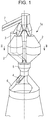
- Fig. 1 and Fig. 2 are schematic diagrams of an embodiment of a bell-less charging device for a blast furnace that is used in the present invention.
- Fig. 1 is an overall perspective view of a bell-less charging device 1a, which is a cutaway view of a portion on top of a furnace body.
- Fig. 2 is a cross-sectional view taken along line II-II of Fig. 1 .
- the bell-less charging device 1a includes three main hoppers 2 and one auxiliary hopper 3. Hopper central axes of the main hoppers 2 are positioned on one imaginary circle that has a center coinciding with a central axis of the furnace body.
- the auxiliary hopper 3 is disposed outside of the plurality of main hoppers 2.
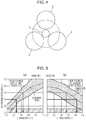
- Fig. 3 and Fig. 4 are schematic diagrams of another embodiment of a bell-less charging device for a blast furnace that is used in the present invention.
- Fig. 3 is an overall perspective view of a bell-less charging device 1b, which is a cutaway view of a portion on top of a furnace body.
- Fig. 4 is a cross-sectional view taken along line IV-IV of Fig. 3 .
- the bell-less charging device 1b also includes three main hoppers 2 and one auxiliary hopper 3. Hopper central axes of the main hoppers 2 are positioned on one imaginary circle that has a center coinciding with a central axis of the furnace body.
- the auxiliary hopper 3 is disposed at a center inside the three main hoppers 2 in a manner such that central axes of a hopper body 3a and an outlet 3b of the auxiliary hopper 3 coincide with the central axis of the furnace body of the blast furnace.
- the ore discharged from the main hoppers 2 and the small-size coke discharged from the auxiliary hopper 3 are charged into the blast furnace from a rotating chute 4 by way of a collecting hopper 5.
- reference numeral 6 denotes a blast furnace body
- reference numeral 7 denotes a charging belt conveyor.
- a flow regulating valve (not illustrated) is provided at the outlet of the auxiliary hopper 3 to control a rate of discharge of the small-size coke.
- Non Patent Literature 1 states that raw materials charged into a region defined by a blast furnace dimensionless radius of 0.12 or less reach a deadman (the blast furnace dimensionless radius is a dimensionless radius of a furnace determined assuming that a start point is a furnace center and designated as 0, and an end point is a furnace wall and designated as 1.0). Accordingly, when a raw material having a small particle diameter is charged into a region defined by a dimensionless radius of 0.12 or less, the fine raw material reaches the deadman and, consequently, may interfere with the gas permeability of a deadman portion. This phenomenon can be avoided by charging small-size coke to a region outside of the dimensionless radius of 0.12 (on the furnace wall side).
- Fig. 5 is a graph illustrating a raw material charged range achieved with a rotating chute 4, the charged range being illustrated in terms of a relationship between the dimensionless radius and a charge ratio.
- the charged range illustrated in Fig. 5 is a range determined using a 1/20-scale model testing device, which is illustrated in Fig. 9 .
- Fig. 5(a) illustrates a raw material charged range associated with a case in which raw materials are sequentially charged from the furnace center side toward the furnace wall side.
- Fig. 5(b) illustrates a raw material charged range associated with a case in which raw materials are sequentially charged from the furnace wall side toward the furnace center side.
- the term “charged range” refers to a range in which raw materials spread in furnace radial directions when the raw materials have been charged into a blast furnace from the rotating chute 4.
- a raw material deposition surface in a top of a blast furnace has a mortar-like shape such that a central portion of the furnace is located at a minimum height.
- a charge center position is defined as any of the positions on which the raw materials from the rotating chute 4 fall, on the sloping surface.
- a range in which the raw materials spread from the charge center position toward the furnace center and the furnace wall and are deposited is designated as the charged range. In a case where the rotating chute 4 is moved from the furnace center side toward the furnace wall side, the charging of raw materials begins from a lower position of the sloping surface having a mortar-like shape, and, therefore, spreading of the raw materials toward the furnace center is inhibited.
- the charged range is narrower in a case where raw materials are charged by moving the rotating chute 4 from the furnace center side toward the furnace wall side than in a case where raw materials are charged by moving the rotating chute 4 from the furnace wall side toward the furnace center side.
- the "charge ratio" on the horizontal axis is a proportion of the ore that has been charged associated with the corresponding charge position in the furnace radial direction, based on a total amount of the ore to be charged per batch, in a case where amounts of raw materials per batch are sequentially charged by using the rotating chute 4 from the furnace center side toward the furnace wall side or from the furnace wall side toward the furnace center side.
- a "charge ratio of 0.1" indicates that charging of 10 mass% of ore, based on the total amount of the ore to be charged per batch, has been completed in association with the corresponding charge position.
- Fig. 6 is a vertical cross-sectional view of an uppermost portion of raw material charge layers in a furnace.
- the charged range and the charge center position, which is a center of the range, are schematically illustrated in Fig. 6 .
- Fig. 5(a) in a case where raw materials are sequentially charged from the furnace center side toward the furnace wall side, one way to avoid small-size coke from being charged into a region defined by a dimensionless radius of 0.12 or less is to ensure that the small-size coke is charged when or after the charge ratio has become 0.15 or greater.
- Fig. 5(b) in a case where raw materials are sequentially charged from the furnace wall side toward the furnace center side, one way to avoid small-size coke from being charged into a region defined by a dimensionless radius of 0.12 or less is to ensure that the small-size coke is charged while the charge ratio is 0.9 or less.
- a preferred region into which small-size coke is to be mixed is a region defined by a charge ratio of 0.15 or greater in a case where raw materials are sequentially charged from the furnace center side toward the furnace wall side and is a region defined by a charge ratio of 0.9 or less in a case where raw materials are sequentially charged from the furnace wall side toward the furnace center side.
- the rotating chute 4 in a case where the ore charged in a main hopper 2 is discharged and then sequentially charged from the furnace center side toward the furnace wall side by using the rotating chute 4 (a first method for charging raw materials of the present invention), only the ore is charged from the rotating chute 4 after the charging of the ore is started, at least until charging of 15 mass% of the ore is completed based on the total amount of the ore to be charged per batch; then, at a point in time, the discharging of the small-size coke charged in the auxiliary hopper 3 is started; and then, the small-size coke is charged together with the ore from the rotating chute 4 for a time period.
- the time at which the discharging of the small-size coke is to be started may be the point in time at which the charging of 15 mass% of the ore is completed based on the total amount of the ore to be charged per batch or may be some point in time after a certain time period elapses after the charging of 15 mass% of the ore is completed based on the total amount of the ore to be charged per batch.
- the discharging of the small-size coke may be performed until the charging of the total amount of the ore is completed or may be stopped before the charging of the total amount of the ore is completed.
- the time at which the discharging of the small-size coke is to be started and the time period during which the discharging of the small-size coke is to be performed may be determined in accordance with the small-size coke mixed state that is required.
- the discharging of the small-size coke charged in the auxiliary hopper 3 is started simultaneously with the start of the charging of the ore or at a point in time after the start of the charging, then the small-size coke is charged together with the ore from the rotating chute 4, and the discharging of the small-size coke is stopped at least before the point in time at which charging of 90 mass% of the ore is completed based on the total amount of the ore to be charged per batch.
- the time at which the discharging of the small-size coke is to be started and the time period during which the discharging of the small-size coke is to be performed may be determined in accordance with the small-size coke mixed state that is required.
- Fig. 7 is a graph illustrating a radial distribution of a standard ore layer thickness.
- the vertical axis represents the "ore layer thickness/total layer thickness (ore layer thickness + coke layer thickness)" of the uppermost portion of the charge layers, and the horizontal axis represents the dimensionless radius.
- the ore layer thickness is large particularly in the region defined by dimensionless radii of 0.4 to 0.6. In this region, a reaction load of the ore is high, and, therefore, it is presumed that by mixing a large amount of small-size coke into the region, an effect of the mixed coke of promoting the reduction reaction of ore can be produced.
- a large amount of small-size coke can be charged into such a region by ensuring that raw materials containing a large amount of coke mixed therewith is charged in a manner such that the charge center position, illustrated in Fig. 6 , is within the region defined by dimensionless radii of 0.4 to 0.6.
- the region defined by dimensionless radii of 0.4 to 0.6 corresponds to a region defined by charge ratios of 0.27 to 0.46 in a case where raw materials are sequentially charged from the furnace center side toward the furnace wall side and corresponds to a region defined by charge ratios of 0.54 to 0.83 in a case where raw materials are sequentially charged from the furnace wall side toward the furnace center side.
- the rate of discharge of the small-size coke to be discharged from the auxiliary hopper 3 be increased compared with a rate of discharge employed for a different time period.
- a large amount of small-size coke can be charged into the region defined by the above-mentioned dimensionless radii, and, therefore, the reduction reaction of ore can be promoted.
- Fig. 8 is a graph illustrating a raw material charged range and a charge center position, which are illustrated in terms of a relationship between the dimensionless radius and the charge ratio. As illustrated in Fig. 8 , the region defined by dimensionless radii of 0.4 to 0.6, with respect to the charge center position, corresponds to a region defined by charge ratios of 0.27 to 0.46.
- the rate of discharge of the small-size coke to be discharged from the auxiliary hopper 3 be increased compared with the rate of discharge employed for a different time period.
- the time period from the point in time at which charging of 27 mass% of the ore is completed to the point in time at which charging of 46 mass% of the ore is completed, based on the total amount of the ore to be charged per batch corresponds to a region in which the thickness of the deposited ore is large within the furnace, and, therefore, it is expected that mixing a large amount of small-size coke into this region promotes the reduction reaction of ore.
- the rate of discharge of the small-size coke be 1.5 to 2 times the rate of discharge employed for a different time period.
- the rate of discharge of the small-size coke is 1.5 times or greater the rate of discharge employed for a different time period, the reduction reaction of ore is noticeably promoted.
- the rate of discharge of the small-size coke to be discharged from the auxiliary hopper 3 be increased compared with the rate of discharge employed for a different time period.
- the time period from the point in time at which charging of 54 mass% of the ore is completed to the point in time at which charging of 83 mass% of the ore is completed, based on the total amount of the ore to be charged per batch corresponds to a region in which the thickness of the deposited ore is large within the furnace, and, therefore, it is expected that mixing a large amount of small-size coke into this region promotes the reduction reaction of ore.
- the rate of discharge of the small-size coke be 1.5 to 2 times the rate of discharge employed for a different time period.
- a gas composition distribution in a furnace radial direction within the blast furnace be measured at the furnace top portion or at a shaft upper portion to determine a distribution of a CO gas utilization ratio associated with the furnace radial direction, and, for a region in the furnace radial direction in which the CO gas utilization ratio is greater than or equal to an average value of the CO gas utilization ratio associated with the furnace radial direction, the rate of discharge of the small-size coke to be discharged from the auxiliary hopper 3 be increased compared with a rate of discharge employed for a different region in the furnace radial direction.
- a region in which the CO gas utilization ratio associated with the furnace radial direction is high corresponds to a region that has a large ore layer thickness and, therefore, has a high ore reduction load. Accordingly, it is expected that mixing a large amount of small-size coke into such a region promotes the reduction reaction of ore. In this case, too, for a reason similar to that described above, it is preferable that the rate of discharge of the small-size coke be set to be 1.5 to 2 times the rate of discharge employed for a different region in the furnace radial direction.
- CO gas utilization ratio 100 ⁇ volume percentage of CO 2 / volume percentage of CO + volume percentage of CO 2
- a furnace top gas probe or a shaft gas probe is inserted in the furnace radial direction, and the gas within the furnace is sampled in 5 or greater and 10 or less locations in the furnace radial direction.
- the samples are then subjected to gas analysis to determine the compositions of the gas of the locations in the furnace radial direction. From the compositions of the gas of the locations in the furnace radial direction, the gas utilization ratio of each of the locations in the furnace radial direction and a distribution of the CO gas utilization ratio associated with the furnace radial direction can be determined.
- the average value of the CO gas utilization ratio is an arithmetic mean of the CO gas utilization ratios of all the measurement locations.
- the absolute values of the rate vectors of the raw material discharged from the main hoppers 2 and the raw material discharged from the auxiliary hopper 3 are the same regarding all the main hoppers 2, and, therefore, a difference in the position on which the raw material flow falls such as that described above does not occur. Accordingly, the position on which the raw materials fall can be easily controlled with high precision. Since the auxiliary hopper 3 is disposed directly above the collecting hopper 5, there is no need to provide a raw material flow path passing from the auxiliary hopper 3 to the collecting hopper 5, and, for example, the time at which the discharging is to be initiated can be easily adjusted.
- an amount of small-size coke for a plurality of charges is charged into the auxiliary hopper 3, and, from the auxiliary hopper 3, an amount of the small-size coke per charge is discharged in batches. Accordingly, the pressure adjustment time associated with the discharging of raw materials can be reduced, and as a result, the production volume of a blast furnace can be maintained even in a case where a small-amount raw material is to be charged into the blast furnace by using a discrete auxiliary hopper.
- FIG. 9 is a schematic diagram of a model testing device used in Examples.
- a flow regulating valve (not illustrated) was disposed at an outlet of an auxiliary hopper of the model testing device to control the rate of discharge of small-size coke.
- ore was charged into main hoppers, and small-size coke was charged into the auxiliary hopper.
- the small-size coke was discharged from the auxiliary hopper during a portion of the time period during which the ore was discharged from the main hoppers.
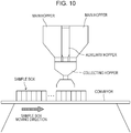
- Fig. 10 is a diagram illustrating how discharged raw materials, which were discharged from the model testing device, were collected in portions.
- the rotating chute was removed from the model testing device, a plurality of sample boxes were mounted onto a feed conveyor, and the sample boxes were moved at a constant speed synchronously with the discharging of raw materials. Accordingly, the discharged raw materials were collected in portions.
- the discharged raw materials that were collected were subjected to specific gravity separation, which utilized the difference in specific gravity between the ore and the coke, to determine the ratio of the small-size coke in the discharged raw materials.
- Fig. 11 is a graph illustrating a relationship between the mixed coke rate and the charge ratio associated with the case in which raw materials were sequentially charged from the furnace center side toward the furnace wall side.
- the small-size coke was discharged when or after the charge ratio reached 0.15, and in addition, the amount of the small-size coke discharged from the auxiliary hopper could be controlled; thus, in Invention Example 1, the mixed coke rate was substantially uniform throughout the whole time period during which the small-size coke was discharged. In Invention Examples 2 and 3, the mixed coke rate was increased particularly in an intermediate period of the discharging, which was associated with a large ore layer thickness.
- Fig. 12 is a graph illustrating a relationship between the mixed coke rate and the charge ratio associated with the case in which raw materials were sequentially charged from the furnace wall side toward the furnace center side.
- Comparative Example 2 in which a method of the related art was used as with Comparative Example 1 of Fig. 11 , an influence of segregation of the small-size coke and the like existed in the main hoppers, and, therefore, it was difficult to drastically change the mixed coke rate.
- Comparative Example 3 the charging of ore from the main hoppers and the charging of small-size coke from the auxiliary hopper were carried out simultaneously, and the small-size coke was mixed with the ore substantially uniformly over the range from the furnace wall side to the furnace center side.
- Table 1 summarizes the results of an evaluation of the operation conditions of Examples and Comparative Examples, which was conducted by using a blast furnace operation prediction model. As shown in Table 1, Invention Examples 1 to 5 had a lower reduction agent rate and a lower pressure drop of the burden layer than Comparative Examples 1 to 3. These results demonstrate that charging ore and small-size coke as in any of Invention Examples 1 to 5 results in improved mixing characteristics of small-size coke, which in turn improves gas permeability and reducibility and, consequently, lowers the reduction agent rate of a blast furnace.
Landscapes
- Engineering & Computer Science (AREA)
- Chemical & Material Sciences (AREA)
- Mechanical Engineering (AREA)
- General Engineering & Computer Science (AREA)
- Manufacturing & Machinery (AREA)
- Materials Engineering (AREA)
- Metallurgy (AREA)
- Organic Chemistry (AREA)
- Manufacture Of Iron (AREA)
Applications Claiming Priority (2)
| Application Number | Priority Date | Filing Date | Title |
|---|---|---|---|
| JP2018066458 | 2018-03-30 | ||
| PCT/JP2019/008261 WO2019187997A1 (fr) | 2018-03-30 | 2019-03-04 | Procédé de chargement de matières premières dans un haut fourneau |
Publications (3)
| Publication Number | Publication Date |
|---|---|
| EP3760744A1 true EP3760744A1 (fr) | 2021-01-06 |
| EP3760744A4 EP3760744A4 (fr) | 2021-05-05 |
| EP3760744B1 EP3760744B1 (fr) | 2023-09-06 |
Family
ID=68061418
Family Applications (1)
| Application Number | Title | Priority Date | Filing Date |
|---|---|---|---|
| EP19776073.9A Active EP3760744B1 (fr) | 2018-03-30 | 2019-03-04 | Procédé de chargement de matières premières dans un haut fourneau |
Country Status (7)
| Country | Link |
|---|---|
| US (1) | US11680748B2 (fr) |
| EP (1) | EP3760744B1 (fr) |
| JP (1) | JP6558519B1 (fr) |
| KR (1) | KR102456735B1 (fr) |
| CN (1) | CN111989411B (fr) |
| RU (1) | RU2742997C1 (fr) |
| WO (1) | WO2019187997A1 (fr) |
Families Citing this family (3)
| Publication number | Priority date | Publication date | Assignee | Title |
|---|---|---|---|---|
| EP3751010B1 (fr) * | 2018-03-30 | 2024-05-01 | JFE Steel Corporation | Procédé de chargement de matières premières dans un haut fourneau |
| CN116377150B (zh) * | 2023-04-28 | 2025-06-03 | 日照钢铁控股集团有限公司 | 一种低成本大高炉焦炭投放方法及其装置 |
| CN119056330B (zh) * | 2024-11-04 | 2025-01-24 | 常州市艾尔兰特传动机械有限公司 | 一种自动产线连续卸料装置及其工作方法 |
Family Cites Families (24)
| Publication number | Priority date | Publication date | Assignee | Title |
|---|---|---|---|---|
| JPS5243169B2 (fr) | 1973-03-24 | 1977-10-28 | ||
| JPS57207105A (en) | 1981-06-16 | 1982-12-18 | Sumitomo Metal Ind Ltd | Charging method for raw material into bell-less type blast furnace |
| JPS5941402A (ja) | 1982-09-02 | 1984-03-07 | Nippon Kokan Kk <Nkk> | 高炉操業法 |
| JPS60208404A (ja) * | 1984-03-31 | 1985-10-21 | Kawasaki Steel Corp | 高炉原料装入方法およびその装置 |
| JP2731829B2 (ja) * | 1989-03-08 | 1998-03-25 | 新日本製鐵株式会社 | 高炉操業法 |
| JP2820478B2 (ja) | 1990-01-16 | 1998-11-05 | 川崎製鉄株式会社 | ベルレス高炉における原料装入方法 |
| SU1788017A1 (ru) * | 1990-06-04 | 1993-01-15 | Cherepovets Metall Kom | Cпocoб зaгpузkи дomehhoй пeчи |
| RU2078141C1 (ru) * | 1993-10-08 | 1997-04-27 | Акционерное общество открытого типа "Северсталь" | Способ загрузки шихтовых материалов в доменную печь |
| JPH07268411A (ja) * | 1994-03-29 | 1995-10-17 | Kawasaki Steel Corp | 高炉の炉芯活性化方法 |
| RU2094470C1 (ru) * | 1995-05-15 | 1997-10-27 | Акционерное общество "Новолипецкий металлургический комбинат" | Способ ведения доменной плавки |
| JPH0987710A (ja) * | 1995-09-28 | 1997-03-31 | Kawasaki Steel Corp | 低Si高炉操業方法 |
| JP3948352B2 (ja) * | 2002-06-07 | 2007-07-25 | 住友金属工業株式会社 | 高炉の操業方法およびベルレス式装入装置 |
| KR100704691B1 (ko) | 2002-08-29 | 2007-04-10 | 제이에프이 스틸 가부시키가이샤 | 벨리스 고로의 원료 장입방법 |
| JP4269847B2 (ja) | 2002-08-30 | 2009-05-27 | Jfeスチール株式会社 | ベルレス高炉の原料装入方法 |
| JP4114626B2 (ja) * | 2004-04-02 | 2008-07-09 | 住友金属工業株式会社 | 高炉の操業方法 |
| EP1811044A1 (fr) * | 2006-01-20 | 2007-07-25 | Paul Wurth S.A. | Trémie à trois d'un haut fourneau |
| EP1811045A1 (fr) * | 2006-01-20 | 2007-07-25 | Paul Wurth S.A. | Trémies multiples pour chargement d'un haut fourneau |
| WO2012164889A1 (fr) * | 2011-05-31 | 2012-12-06 | 新日鐵住金株式会社 | Dispositif de chargement d'un matériau de départ pour haut-fourneau, et procédé de chargement d'un matériau de départ l'utilisant |
| JP2013172045A (ja) | 2012-02-22 | 2013-09-02 | Hitachi Aic Inc | フィルムコンデンサ |
| JP5910735B2 (ja) | 2012-05-18 | 2016-04-27 | Jfeスチール株式会社 | 高炉への原料装入方法 |
| WO2013172043A1 (fr) | 2012-05-18 | 2013-11-21 | Jfeスチール株式会社 | Procédé de chargement d'une matière brute dans un haut-fourneau |
| JP6244874B2 (ja) | 2013-12-16 | 2017-12-13 | 新日鐵住金株式会社 | 原料装入方法 |
| CN107208166B (zh) | 2015-02-03 | 2019-04-16 | 杰富意钢铁株式会社 | 向高炉中装入原料的方法 |
| JP6183412B2 (ja) | 2015-05-28 | 2017-08-23 | Jfeスチール株式会社 | 高炉への原料装入装置 |
-
2019
- 2019-03-04 CN CN201980023639.2A patent/CN111989411B/zh active Active
- 2019-03-04 KR KR1020207028209A patent/KR102456735B1/ko active Active
- 2019-03-04 US US17/042,392 patent/US11680748B2/en active Active
- 2019-03-04 EP EP19776073.9A patent/EP3760744B1/fr active Active
- 2019-03-04 JP JP2019526618A patent/JP6558519B1/ja active Active
- 2019-03-04 WO PCT/JP2019/008261 patent/WO2019187997A1/fr not_active Ceased
- 2019-03-04 RU RU2020132094A patent/RU2742997C1/ru active
Also Published As
| Publication number | Publication date |
|---|---|
| KR102456735B1 (ko) | 2022-10-19 |
| BR112020019880A2 (pt) | 2021-01-05 |
| WO2019187997A1 (fr) | 2019-10-03 |
| KR20200124742A (ko) | 2020-11-03 |
| JP6558519B1 (ja) | 2019-08-14 |
| RU2742997C1 (ru) | 2021-02-12 |
| CN111989411B (zh) | 2022-07-08 |
| US20210033339A1 (en) | 2021-02-04 |
| EP3760744A4 (fr) | 2021-05-05 |
| JPWO2019187997A1 (ja) | 2020-04-30 |
| EP3760744B1 (fr) | 2023-09-06 |
| US11680748B2 (en) | 2023-06-20 |
| CN111989411A (zh) | 2020-11-24 |
Similar Documents
| Publication | Publication Date | Title |
|---|---|---|
| EP3760744B1 (fr) | Procédé de chargement de matières premières dans un haut fourneau | |
| EP2851438B1 (fr) | Procédé pour le chargement de matière première dans un haut-fourneau | |
| TWI239355B (en) | Method for charging material into blast furnace with distributing chute instead of bells | |
| EP2851435B1 (fr) | Procédé de chargement d'une matière première dans un haut-fourneau | |
| EP2851436B1 (fr) | Procédé de chargement d'une matière première dans un fourneau | |
| JP4114626B2 (ja) | 高炉の操業方法 | |
| US20240052439A1 (en) | Method for charging raw materials into blast furnace | |
| US12098437B2 (en) | Method for charging raw materials into blast furnace | |
| JP5338309B2 (ja) | 高炉への原料装入方法 | |
| JP6627718B2 (ja) | 高炉への原料装入方法 | |
| JP5012576B2 (ja) | ベル式高炉の原料装入方法 | |
| JP7363751B2 (ja) | 高炉の原料装入方法 | |
| JP7372600B2 (ja) | 高炉の原料装入方法 | |
| EP4083235A1 (fr) | Procédé pour charger une matière première dans un haut-fourneau | |
| JP6627717B2 (ja) | 高炉への原料装入方法 | |
| JPH0512403B2 (fr) | ||
| BR112020019880B1 (pt) | Método para carregamento de matérias-primas em alto-forno | |
| JP2025109336A (ja) | 高炉の原料装入方法 | |
| JP2008095206A (ja) | 高炉への原料装入方法 | |
| JP2002348604A (ja) | 高炉への原料装入方法 |
Legal Events
| Date | Code | Title | Description |
|---|---|---|---|
| STAA | Information on the status of an ep patent application or granted ep patent |
Free format text: STATUS: THE INTERNATIONAL PUBLICATION HAS BEEN MADE |
|
| PUAI | Public reference made under article 153(3) epc to a published international application that has entered the european phase |
Free format text: ORIGINAL CODE: 0009012 |
|
| STAA | Information on the status of an ep patent application or granted ep patent |
Free format text: STATUS: REQUEST FOR EXAMINATION WAS MADE |
|
| 17P | Request for examination filed |
Effective date: 20200929 |
|
| AK | Designated contracting states |
Kind code of ref document: A1 Designated state(s): AL AT BE BG CH CY CZ DE DK EE ES FI FR GB GR HR HU IE IS IT LI LT LU LV MC MK MT NL NO PL PT RO RS SE SI SK SM TR |
|
| AX | Request for extension of the european patent |
Extension state: BA ME |
|
| A4 | Supplementary search report drawn up and despatched |
Effective date: 20210409 |
|
| RIC1 | Information provided on ipc code assigned before grant |
Ipc: C21B 5/00 20060101AFI20210401BHEP Ipc: C21B 7/18 20060101ALI20210401BHEP Ipc: C21B 7/20 20060101ALI20210401BHEP Ipc: F27B 1/20 20060101ALI20210401BHEP Ipc: F27D 3/10 20060101ALI20210401BHEP |
|
| DAV | Request for validation of the european patent (deleted) | ||
| DAX | Request for extension of the european patent (deleted) | ||
| GRAP | Despatch of communication of intention to grant a patent |
Free format text: ORIGINAL CODE: EPIDOSNIGR1 |
|
| STAA | Information on the status of an ep patent application or granted ep patent |
Free format text: STATUS: GRANT OF PATENT IS INTENDED |
|
| INTG | Intention to grant announced |
Effective date: 20230413 |
|
| RIN1 | Information on inventor provided before grant (corrected) |
Inventor name: SATO, TAKESHI Inventor name: OGASAWARA, YASUSHI Inventor name: ICHIKAWA, KAZUHIRA |
|
| GRAS | Grant fee paid |
Free format text: ORIGINAL CODE: EPIDOSNIGR3 |
|
| GRAA | (expected) grant |
Free format text: ORIGINAL CODE: 0009210 |
|
| STAA | Information on the status of an ep patent application or granted ep patent |
Free format text: STATUS: THE PATENT HAS BEEN GRANTED |
|
| AK | Designated contracting states |
Kind code of ref document: B1 Designated state(s): AL AT BE BG CH CY CZ DE DK EE ES FI FR GB GR HR HU IE IS IT LI LT LU LV MC MK MT NL NO PL PT RO RS SE SI SK SM TR |
|
| REG | Reference to a national code |
Ref country code: GB Ref legal event code: FG4D |
|
| REG | Reference to a national code |
Ref country code: CH Ref legal event code: EP |
|
| REG | Reference to a national code |
Ref country code: DE Ref legal event code: R096 Ref document number: 602019036897 Country of ref document: DE |
|
| REG | Reference to a national code |
Ref country code: IE Ref legal event code: FG4D |
|
| REG | Reference to a national code |
Ref country code: LT Ref legal event code: MG9D |
|
| REG | Reference to a national code |
Ref country code: NL Ref legal event code: MP Effective date: 20230906 |
|
| PG25 | Lapsed in a contracting state [announced via postgrant information from national office to epo] |
Ref country code: GR Free format text: LAPSE BECAUSE OF FAILURE TO SUBMIT A TRANSLATION OF THE DESCRIPTION OR TO PAY THE FEE WITHIN THE PRESCRIBED TIME-LIMIT Effective date: 20231207 |
|
| PG25 | Lapsed in a contracting state [announced via postgrant information from national office to epo] |
Ref country code: SE Free format text: LAPSE BECAUSE OF FAILURE TO SUBMIT A TRANSLATION OF THE DESCRIPTION OR TO PAY THE FEE WITHIN THE PRESCRIBED TIME-LIMIT Effective date: 20230906 Ref country code: RS Free format text: LAPSE BECAUSE OF FAILURE TO SUBMIT A TRANSLATION OF THE DESCRIPTION OR TO PAY THE FEE WITHIN THE PRESCRIBED TIME-LIMIT Effective date: 20230906 Ref country code: NO Free format text: LAPSE BECAUSE OF FAILURE TO SUBMIT A TRANSLATION OF THE DESCRIPTION OR TO PAY THE FEE WITHIN THE PRESCRIBED TIME-LIMIT Effective date: 20231206 Ref country code: LV Free format text: LAPSE BECAUSE OF FAILURE TO SUBMIT A TRANSLATION OF THE DESCRIPTION OR TO PAY THE FEE WITHIN THE PRESCRIBED TIME-LIMIT Effective date: 20230906 Ref country code: LT Free format text: LAPSE BECAUSE OF FAILURE TO SUBMIT A TRANSLATION OF THE DESCRIPTION OR TO PAY THE FEE WITHIN THE PRESCRIBED TIME-LIMIT Effective date: 20230906 Ref country code: HR Free format text: LAPSE BECAUSE OF FAILURE TO SUBMIT A TRANSLATION OF THE DESCRIPTION OR TO PAY THE FEE WITHIN THE PRESCRIBED TIME-LIMIT Effective date: 20230906 Ref country code: GR Free format text: LAPSE BECAUSE OF FAILURE TO SUBMIT A TRANSLATION OF THE DESCRIPTION OR TO PAY THE FEE WITHIN THE PRESCRIBED TIME-LIMIT Effective date: 20231207 Ref country code: FI Free format text: LAPSE BECAUSE OF FAILURE TO SUBMIT A TRANSLATION OF THE DESCRIPTION OR TO PAY THE FEE WITHIN THE PRESCRIBED TIME-LIMIT Effective date: 20230906 |
|
| REG | Reference to a national code |
Ref country code: AT Ref legal event code: MK05 Ref document number: 1608641 Country of ref document: AT Kind code of ref document: T Effective date: 20230906 |
|
| PG25 | Lapsed in a contracting state [announced via postgrant information from national office to epo] |
Ref country code: NL Free format text: LAPSE BECAUSE OF FAILURE TO SUBMIT A TRANSLATION OF THE DESCRIPTION OR TO PAY THE FEE WITHIN THE PRESCRIBED TIME-LIMIT Effective date: 20230906 |
|
| PG25 | Lapsed in a contracting state [announced via postgrant information from national office to epo] |
Ref country code: IS Free format text: LAPSE BECAUSE OF FAILURE TO SUBMIT A TRANSLATION OF THE DESCRIPTION OR TO PAY THE FEE WITHIN THE PRESCRIBED TIME-LIMIT Effective date: 20240106 |
|
| PG25 | Lapsed in a contracting state [announced via postgrant information from national office to epo] |
Ref country code: AT Free format text: LAPSE BECAUSE OF FAILURE TO SUBMIT A TRANSLATION OF THE DESCRIPTION OR TO PAY THE FEE WITHIN THE PRESCRIBED TIME-LIMIT Effective date: 20230906 |
|
| PG25 | Lapsed in a contracting state [announced via postgrant information from national office to epo] |
Ref country code: ES Free format text: LAPSE BECAUSE OF FAILURE TO SUBMIT A TRANSLATION OF THE DESCRIPTION OR TO PAY THE FEE WITHIN THE PRESCRIBED TIME-LIMIT Effective date: 20230906 |
|
| PG25 | Lapsed in a contracting state [announced via postgrant information from national office to epo] |
Ref country code: SM Free format text: LAPSE BECAUSE OF FAILURE TO SUBMIT A TRANSLATION OF THE DESCRIPTION OR TO PAY THE FEE WITHIN THE PRESCRIBED TIME-LIMIT Effective date: 20230906 Ref country code: RO Free format text: LAPSE BECAUSE OF FAILURE TO SUBMIT A TRANSLATION OF THE DESCRIPTION OR TO PAY THE FEE WITHIN THE PRESCRIBED TIME-LIMIT Effective date: 20230906 Ref country code: IS Free format text: LAPSE BECAUSE OF FAILURE TO SUBMIT A TRANSLATION OF THE DESCRIPTION OR TO PAY THE FEE WITHIN THE PRESCRIBED TIME-LIMIT Effective date: 20240106 Ref country code: ES Free format text: LAPSE BECAUSE OF FAILURE TO SUBMIT A TRANSLATION OF THE DESCRIPTION OR TO PAY THE FEE WITHIN THE PRESCRIBED TIME-LIMIT Effective date: 20230906 Ref country code: EE Free format text: LAPSE BECAUSE OF FAILURE TO SUBMIT A TRANSLATION OF THE DESCRIPTION OR TO PAY THE FEE WITHIN THE PRESCRIBED TIME-LIMIT Effective date: 20230906 Ref country code: CZ Free format text: LAPSE BECAUSE OF FAILURE TO SUBMIT A TRANSLATION OF THE DESCRIPTION OR TO PAY THE FEE WITHIN THE PRESCRIBED TIME-LIMIT Effective date: 20230906 Ref country code: AT Free format text: LAPSE BECAUSE OF FAILURE TO SUBMIT A TRANSLATION OF THE DESCRIPTION OR TO PAY THE FEE WITHIN THE PRESCRIBED TIME-LIMIT Effective date: 20230906 Ref country code: SK Free format text: LAPSE BECAUSE OF FAILURE TO SUBMIT A TRANSLATION OF THE DESCRIPTION OR TO PAY THE FEE WITHIN THE PRESCRIBED TIME-LIMIT Effective date: 20230906 Ref country code: PT Free format text: LAPSE BECAUSE OF FAILURE TO SUBMIT A TRANSLATION OF THE DESCRIPTION OR TO PAY THE FEE WITHIN THE PRESCRIBED TIME-LIMIT Effective date: 20240108 |
|
| PG25 | Lapsed in a contracting state [announced via postgrant information from national office to epo] |
Ref country code: PL Free format text: LAPSE BECAUSE OF FAILURE TO SUBMIT A TRANSLATION OF THE DESCRIPTION OR TO PAY THE FEE WITHIN THE PRESCRIBED TIME-LIMIT Effective date: 20230906 Ref country code: IT Free format text: LAPSE BECAUSE OF FAILURE TO SUBMIT A TRANSLATION OF THE DESCRIPTION OR TO PAY THE FEE WITHIN THE PRESCRIBED TIME-LIMIT Effective date: 20230906 |
|
| REG | Reference to a national code |
Ref country code: DE Ref legal event code: R097 Ref document number: 602019036897 Country of ref document: DE |
|
| PG25 | Lapsed in a contracting state [announced via postgrant information from national office to epo] |
Ref country code: DK Free format text: LAPSE BECAUSE OF FAILURE TO SUBMIT A TRANSLATION OF THE DESCRIPTION OR TO PAY THE FEE WITHIN THE PRESCRIBED TIME-LIMIT Effective date: 20230906 |
|
| PLBE | No opposition filed within time limit |
Free format text: ORIGINAL CODE: 0009261 |
|
| STAA | Information on the status of an ep patent application or granted ep patent |
Free format text: STATUS: NO OPPOSITION FILED WITHIN TIME LIMIT |
|
| PG25 | Lapsed in a contracting state [announced via postgrant information from national office to epo] |
Ref country code: DK Free format text: LAPSE BECAUSE OF FAILURE TO SUBMIT A TRANSLATION OF THE DESCRIPTION OR TO PAY THE FEE WITHIN THE PRESCRIBED TIME-LIMIT Effective date: 20230906 Ref country code: SI Free format text: LAPSE BECAUSE OF FAILURE TO SUBMIT A TRANSLATION OF THE DESCRIPTION OR TO PAY THE FEE WITHIN THE PRESCRIBED TIME-LIMIT Effective date: 20230906 |
|
| 26N | No opposition filed |
Effective date: 20240607 |
|
| REG | Reference to a national code |
Ref country code: DE Ref legal event code: R119 Ref document number: 602019036897 Country of ref document: DE |
|
| REG | Reference to a national code |
Ref country code: CH Ref legal event code: PL |
|
| PG25 | Lapsed in a contracting state [announced via postgrant information from national office to epo] |
Ref country code: BG Free format text: LAPSE BECAUSE OF FAILURE TO SUBMIT A TRANSLATION OF THE DESCRIPTION OR TO PAY THE FEE WITHIN THE PRESCRIBED TIME-LIMIT Effective date: 20230906 |
|
| PG25 | Lapsed in a contracting state [announced via postgrant information from national office to epo] |
Ref country code: LU Free format text: LAPSE BECAUSE OF NON-PAYMENT OF DUE FEES Effective date: 20240304 |
|
| PG25 | Lapsed in a contracting state [announced via postgrant information from national office to epo] |
Ref country code: MC Free format text: LAPSE BECAUSE OF FAILURE TO SUBMIT A TRANSLATION OF THE DESCRIPTION OR TO PAY THE FEE WITHIN THE PRESCRIBED TIME-LIMIT Effective date: 20230906 |
|
| GBPC | Gb: european patent ceased through non-payment of renewal fee |
Effective date: 20240304 |
|
| PG25 | Lapsed in a contracting state [announced via postgrant information from national office to epo] |
Ref country code: MC Free format text: LAPSE BECAUSE OF FAILURE TO SUBMIT A TRANSLATION OF THE DESCRIPTION OR TO PAY THE FEE WITHIN THE PRESCRIBED TIME-LIMIT Effective date: 20230906 Ref country code: LU Free format text: LAPSE BECAUSE OF NON-PAYMENT OF DUE FEES Effective date: 20240304 Ref country code: BG Free format text: LAPSE BECAUSE OF FAILURE TO SUBMIT A TRANSLATION OF THE DESCRIPTION OR TO PAY THE FEE WITHIN THE PRESCRIBED TIME-LIMIT Effective date: 20230906 |
|
| REG | Reference to a national code |
Ref country code: BE Ref legal event code: MM Effective date: 20240331 |
|
| PG25 | Lapsed in a contracting state [announced via postgrant information from national office to epo] |
Ref country code: DE Free format text: LAPSE BECAUSE OF NON-PAYMENT OF DUE FEES Effective date: 20241001 |
|
| PG25 | Lapsed in a contracting state [announced via postgrant information from national office to epo] |
Ref country code: BE Free format text: LAPSE BECAUSE OF NON-PAYMENT OF DUE FEES Effective date: 20240331 |
|
| PG25 | Lapsed in a contracting state [announced via postgrant information from national office to epo] |
Ref country code: GB Free format text: LAPSE BECAUSE OF NON-PAYMENT OF DUE FEES Effective date: 20240304 |
|
| PG25 | Lapsed in a contracting state [announced via postgrant information from national office to epo] |
Ref country code: FR Free format text: LAPSE BECAUSE OF NON-PAYMENT OF DUE FEES Effective date: 20240331 |
|
| PG25 | Lapsed in a contracting state [announced via postgrant information from national office to epo] |
Ref country code: IE Free format text: LAPSE BECAUSE OF NON-PAYMENT OF DUE FEES Effective date: 20240304 |
|
| PG25 | Lapsed in a contracting state [announced via postgrant information from national office to epo] |
Ref country code: IE Free format text: LAPSE BECAUSE OF NON-PAYMENT OF DUE FEES Effective date: 20240304 Ref country code: GB Free format text: LAPSE BECAUSE OF NON-PAYMENT OF DUE FEES Effective date: 20240304 Ref country code: FR Free format text: LAPSE BECAUSE OF NON-PAYMENT OF DUE FEES Effective date: 20240331 Ref country code: DE Free format text: LAPSE BECAUSE OF NON-PAYMENT OF DUE FEES Effective date: 20241001 Ref country code: BE Free format text: LAPSE BECAUSE OF NON-PAYMENT OF DUE FEES Effective date: 20240331 Ref country code: CH Free format text: LAPSE BECAUSE OF NON-PAYMENT OF DUE FEES Effective date: 20240331 |
|
| PG25 | Lapsed in a contracting state [announced via postgrant information from national office to epo] |
Ref country code: CY Free format text: LAPSE BECAUSE OF FAILURE TO SUBMIT A TRANSLATION OF THE DESCRIPTION OR TO PAY THE FEE WITHIN THE PRESCRIBED TIME-LIMIT; INVALID AB INITIO Effective date: 20190304 |
|
| PG25 | Lapsed in a contracting state [announced via postgrant information from national office to epo] |
Ref country code: HU Free format text: LAPSE BECAUSE OF FAILURE TO SUBMIT A TRANSLATION OF THE DESCRIPTION OR TO PAY THE FEE WITHIN THE PRESCRIBED TIME-LIMIT; INVALID AB INITIO Effective date: 20190304 |
|
| PGFP | Annual fee paid to national office [announced via postgrant information from national office to epo] |
Ref country code: TR Payment date: 20260302 Year of fee payment: 8 |