EP3761003B1 - Verfahren zum messen der konzentration, der grösse und des zetapotentials von nanopartikeln in flüssigkeiten im streulichtmodus und im fluoreszenzmodus - Google Patents
Verfahren zum messen der konzentration, der grösse und des zetapotentials von nanopartikeln in flüssigkeiten im streulichtmodus und im fluoreszenzmodus Download PDFInfo
- Publication number
- EP3761003B1 EP3761003B1 EP20185891.7A EP20185891A EP3761003B1 EP 3761003 B1 EP3761003 B1 EP 3761003B1 EP 20185891 A EP20185891 A EP 20185891A EP 3761003 B1 EP3761003 B1 EP 3761003B1
- Authority
- EP
- European Patent Office
- Prior art keywords
- scattered light
- fluorescence
- light
- liquid
- nanoparticles
- Prior art date
- Legal status (The legal status is an assumption and is not a legal conclusion. Google has not performed a legal analysis and makes no representation as to the accuracy of the status listed.)
- Active
Links
Images
Classifications
-
- G—PHYSICS
- G01—MEASURING; TESTING
- G01N—INVESTIGATING OR ANALYSING MATERIALS BY DETERMINING THEIR CHEMICAL OR PHYSICAL PROPERTIES
- G01N15/00—Investigating characteristics of particles; Investigating permeability, pore-volume or surface-area of porous materials
- G01N15/02—Investigating particle size or size distribution
- G01N15/0205—Investigating particle size or size distribution by optical means
- G01N15/0211—Investigating a scatter or diffraction pattern
-
- G—PHYSICS
- G01—MEASURING; TESTING
- G01N—INVESTIGATING OR ANALYSING MATERIALS BY DETERMINING THEIR CHEMICAL OR PHYSICAL PROPERTIES
- G01N27/00—Investigating or analysing materials by the use of electric, electrochemical, or magnetic means
- G01N27/26—Investigating or analysing materials by the use of electric, electrochemical, or magnetic means by investigating electrochemical variables; by using electrolysis or electrophoresis
- G01N27/416—Systems
- G01N27/447—Systems using electrophoresis
- G01N27/44704—Details; Accessories
- G01N27/44717—Arrangements for investigating the separated zones, e.g. localising zones
- G01N27/44721—Arrangements for investigating the separated zones, e.g. localising zones by optical means
-
- G—PHYSICS
- G01—MEASURING; TESTING
- G01N—INVESTIGATING OR ANALYSING MATERIALS BY DETERMINING THEIR CHEMICAL OR PHYSICAL PROPERTIES
- G01N15/00—Investigating characteristics of particles; Investigating permeability, pore-volume or surface-area of porous materials
- G01N2015/0038—Investigating nanoparticles
-
- G—PHYSICS
- G01—MEASURING; TESTING
- G01N—INVESTIGATING OR ANALYSING MATERIALS BY DETERMINING THEIR CHEMICAL OR PHYSICAL PROPERTIES
- G01N15/00—Investigating characteristics of particles; Investigating permeability, pore-volume or surface-area of porous materials
- G01N2015/0042—Investigating dispersion of solids
- G01N2015/0053—Investigating dispersion of solids in liquids, e.g. trouble
-
- G—PHYSICS
- G01—MEASURING; TESTING
- G01N—INVESTIGATING OR ANALYSING MATERIALS BY DETERMINING THEIR CHEMICAL OR PHYSICAL PROPERTIES
- G01N15/00—Investigating characteristics of particles; Investigating permeability, pore-volume or surface-area of porous materials
- G01N15/02—Investigating particle size or size distribution
- G01N15/0205—Investigating particle size or size distribution by optical means
- G01N15/0211—Investigating a scatter or diffraction pattern
- G01N2015/0222—Investigating a scatter or diffraction pattern from dynamic light scattering, e.g. photon correlation spectroscopy
-
- G—PHYSICS
- G01—MEASURING; TESTING
- G01N—INVESTIGATING OR ANALYSING MATERIALS BY DETERMINING THEIR CHEMICAL OR PHYSICAL PROPERTIES
- G01N15/00—Investigating characteristics of particles; Investigating permeability, pore-volume or surface-area of porous materials
- G01N15/10—Investigating individual particles
- G01N2015/1027—Determining speed or velocity of a particle
-
- G—PHYSICS
- G01—MEASURING; TESTING
- G01N—INVESTIGATING OR ANALYSING MATERIALS BY DETERMINING THEIR CHEMICAL OR PHYSICAL PROPERTIES
- G01N15/00—Investigating characteristics of particles; Investigating permeability, pore-volume or surface-area of porous materials
- G01N15/10—Investigating individual particles
- G01N2015/1029—Particle size
Definitions
- the invention relates to a method for measuring the concentration, size and zeta potential of nanoparticles in liquids in scattered light mode and in fluorescence mode.
- the evaluation is carried out by heterodyne DLS (dynamic light scattering, ISO 22412).
- Suspensions and emulsions as disperse material systems are frequently occurring forms of particles in liquids. Applications range from printer ink to cosmetic emulsions to pharmaceutical administrations.
- Disperse systems are known to be thermodynamically unstable systems. The length of time for which such dispersions remain stable is of key importance for their applicability. A very frequently observed instability arises from the coagulation of particles, which can lead to irreversible particle size growth or to complete separation between the liquid phase and the particle phase.
- electrostatic stabilization This takes advantage of the fact that the approach of like-charged particles is made more difficult by their electrostatic repulsion. The repulsion is more efficient the higher the ionic charge of the particles at their interface with the medium.
- zeta potential The decisive factor here is the electrostatic particle interface potential, usually called zeta potential. This zeta potential is considered a measure that determines the degree of repulsion between neighboring particles. It is therefore important with regard to the stability of disperse systems.
- a well-known method is classical electrophoresis under the microscope, in particular under the scattered light microscope with the laser and microscope axes at 90° in the electrophoresis measuring arrangement.
- the particles are placed in an electric field. The stronger the zeta potential of the particles, the faster they move in the applied field.
- the measured quantity is the electrophoretic mobility ⁇ e, which is nothing other than the measured velocity v divided by the applied electric field E.
- This ⁇ e is converted into a zeta potential.
- This electrophoresis arrangement is popular when the particle electrophoresis movement can be observed directly in the video and possible interference effects such as convection can be identified.
- the films are automatically evaluated according to the speed distribution of the particles. By using sharply focusable lasers, the lower measurement limit of 1 ⁇ m particle size was reduced to 0.02 ⁇ m. This also applies to the Brownian motion of the particles, which is observed with the same device and from which the particle size can be derived.
- the invention is based on the object of specifying a method for measuring the concentration, size and zeta potential of nanoparticles in liquids in scattered light mode and in fluorescence mode.
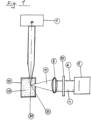
- Fig. 1 shows a representation of Particle Metrix's own PTA nanoparticle tracking measurement arrangement according to the state of the art.
- the imaging optics consist of the lens 6, which is aimed at the particulate sample 28 in the measuring cell 29, and a video camera, which records the movement of the particles.
- the laser 1 as the exciting light source for scattered light and fluorescent light, usually shines at an angle of 90 degrees to it.
- scattered light from the scattered light plane 31 and light from the fluorescence plane 30 are simultaneously registered via the beam path 11 through a liquid lens 8, or a motor-adjustable lens 8, with adjustable focus after passing through a fluorescence filter 10 via a beam path 4.
- Both scattered light and fluorescent light are emitted simultaneously by the same particles, with the scattered light always having a high intensity.
- the problem here is that the scattered light, which is orders of magnitude weaker, Fluorescence light must be separated from the much stronger scattered light signal by an optical edge filter. Due to the necessary resolution and high sensitivity, black and white cameras or grayscale detectors are used, which cannot distinguish the color of the fluorescence from the color of the scattered light.
- the filter has the task of clearly blocking scattered light that comes from the particles and parasitic scattered light that can land on the detector due to an unintentional interaction of the laser with the apparatus.
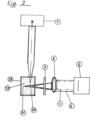
- Fig. 2 shows a representation of an improved version of the Fig. 1 shown arrangement.
- This representation corresponds in many parts to the illustration in Eig. 1.
- the imaging optics consist of the lens 6, which is aimed at the particulate sample 28 in the measuring cell 29, and a video camera or a detector that records the particles.
- the laser 1 is the exciting light source for fluorescent light and scattered light.
- scattered light from the scattered light plane 31 and light from the fluorescence plane 30 are simultaneously registered by a liquid lens 8, or a motor-adjustable lens 8, via a beam path that is not specified in more detail.
- the fluorescence filter 7 is located in the convergent beam path between the liquid lens 8, or a motor-adjustable lens 8, and the sample 28 and not in the parallel beam path directly in front of the video camera 5. This is because in many cases the attenuation of the filter is not sufficient to completely suppress the scattered light.
- the measure described improves the situation by orders of magnitude. If the fluorescence filter is located in the convergent beam path between the lens and the sample, the focus of the scattered light (e.g. 488 nm wavelength) is behind the focus of the fluorescent light (e.g. 510 nm to 560 nm wavelength.
- the optics of the lens "look" either into the scattered light focus or into the fluorescence focus. This leads to a Suppression of stray light by several orders of magnitude when the optics are set to fluorescence. This is even more important the weaker the fluorescence signals are.
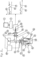
- the Fig.3 shows a representation of a device for determining the concentration, magnitude and zeta potential distribution of nanoparticles in scattered light mode and in fluorescence mode.
- a laser beam 1 is directed from above towards a liquid surface which is located in a container, here a sample vessel 27.
- This liquid is homogenized by a slight movement before a measurement. After the liquid has settled and the container 27 is opened in the direction of the laser beam 1, a measurement can begin.
- the laser beam 1 directed from above is directed onto the liquid via a beam part 14 through a liquid lens, or a motor-driven lens 9 with adjustable focus and an optical protective glass 23.
- the protective glass 23 is made of scratch-resistant material, such as sapphire or diamond.
- the liquid lens 9, or a motor-adjustable lens 9, is used for optimal focusing on a point just below the phase boundary between air and liquid.
- the focus must be approximately 0.1 mm to 1 mm in the liquid.
- the focal length of the liquid lens 9, or a motor-adjustable lens 9, can be moved in a defined manner using an optical control 15.
- the light reflected back by the liquid surface 22 and by the optical protective glass 23 is partly directed by the beam splitter 14 onto a detector 5, whereby a further liquid lens 8, or a motor-adjustable lens 8, serves to focus on the detector 5.
- the beam splitter 14 is not mounted at an exact 45° angle so that partially reflected laser light originating from the protective window 23 does not radiate into the emitting laser 1 in order to avoid undesirable feedback effects on the laser.
- the nanoparticles in sample 28 scatter in all directions according to Brownian motion. This motion is transferred to the scattered light signal as a temporal fluctuation. A portion of the scattered light corresponding to the solid angle of 180 degrees passes through the liquid lens 9 and the beam splitter 14 onto the detector 5. The light reflected from the liquid surface 22, the liquid lens 9 and the optical protective glass 23 and the scattered light from the particles coming from the interior of the sample are collected at the detector 5.
- DLS dynamic light scattering
- the laser component 17 of the total signal 16 can be determined.
- the scattered light component contains the information about the concentration and size distribution of the particles.
- the particle size distribution is calculated from Brownian molecular motion using the well-known DLS method. To do this, the viscosity of the sample of the liquid surrounding the particles must be known. This viscosity exists in tabular form for two temperature values for a wide variety of liquids. To calculate the values above these temperature values, the viscosity can be calculated by a specialist using a simple formula. With the help of a thermistor, the temperature sensor 26, above the vessel 27, the respective temperature is transmitted to the electronic control 3 for calculating the viscosity.
- the liquid lens 9 is adjusted so that the position of the liquid surface is only determined precisely by a bright reflection of the laser beam on the liquid surface 22. Starting from this position of the liquid lens 9, it is adjusted so that the focus is on a precisely determined distance d from the liquid surface in the liquid.
- the distance d can be optimized for different samples if necessary.
- the distance d results from the difference between 22 and 21.
- the imaging lens the liquid lens 8 in the beam path 32, is imaged with its focal point onto the detector 5 in the scattered light mode, whereby the fluorescence filter 10 is not in the beam path.
- the fluorescence filter is pushed into the beam path in front of the detector 5. This shifts the fluorescence focus or the fluorescence plane 30 accordingly and is readjusted using the liquid lens 8. Due to the different positions of the fluorescence focus and the scattered light focus or the scattered light plane 31, the filter effect is increased by orders of magnitude depending on the optical design of the imaging optics.
- the fluorescence filter 10 is removed from the beam path or inserted into the beam path by means of a sliding device 24 and its drive 25.
- the difference in the intensities of the respective detector signals 20 between the scattered light component 16 of the signal and the fluorescence signal 18 is shown in the diagrams on the right side of the Fig.3 plotted on the time axis 19.
- the device is operated by means of a touchscreen 2 and a display
- the electrodes installed in the sample vessel 27 are electroporesis electrodes 12 for a pulsed or modulated field and field tapping electrodes 13 which are used to measure the effective field in the sample chamber 28 in order to be able to reliably calculate the zeta potential. Disturbing effects on the electrodes 12 such as bubble formation therefore do not contribute to the determination of the electric field.
Landscapes
- Chemical & Material Sciences (AREA)
- Life Sciences & Earth Sciences (AREA)
- Health & Medical Sciences (AREA)
- Physics & Mathematics (AREA)
- Analytical Chemistry (AREA)
- Biochemistry (AREA)
- General Health & Medical Sciences (AREA)
- General Physics & Mathematics (AREA)
- Immunology (AREA)
- Pathology (AREA)
- Molecular Biology (AREA)
- Dispersion Chemistry (AREA)
- Chemical Kinetics & Catalysis (AREA)
- Electrochemistry (AREA)
- Investigating, Analyzing Materials By Fluorescence Or Luminescence (AREA)
Description
- Die Erfindung betrifft ein Verfahren zum Messen der Konzentration, der Größe und des Zetapotentials von Nanopartikeln in Flüssigkeiten im Streulichtmodus ind im Fluoreszenzmodus.
- Die Auswertung erfolgt durch heterodyne DLS ( Dynamische Lichtstreuung, ISO 22412). Suspensionen und Emulsionen als disperse Stoffsysteme sind häufig vorkommende Formen von Partikeln in Flüssigkeiten. Die Anwendungen reichen von der Druckertinte über kosmetische Emulsionen bis hin zu pharmazeutischen Verabreichungen. Disperse Systeme sind bekanntermaßen den thermodynamisch instabilen Systemen zuzuordnen. Die Zeitdauer, in der solche Dispersionen stabil bleiben, ist für die Anwendbarkeit von wesentlicher Bedeutung. Eine sehr oft zu beobachtende Instabilität entsteht durch Koagulation von Teilchen die zu irreversiblem Partikelgrößenwachstum bzw. zu völliger Trennung zwischen flüssiger Phase und Partikelphase führen kann. Zur Verhinderung der Koagulation dienen mehrere Vorkehrungen. Eine davon ist die elektrostatische Stabilisierung. Dabei macht man sich zunutze, dass die Annäherung gleichsinnig geladener Teilchen durch deren elektrostatische Abstoßung erschwert wird. Die Abstoßung ist umso effizienter, je höher die ionische Ladung der Teilchen auf ihrer Grenzfläche zum Medium ist.
- Maßgebend hierfür ist das elektrostatische Partikel-Grenzflächenpotential, meist Zetapotential genannt. Dieses Zetapotential wird als ein Maß angesehen, das den Grad der Abstoßung zwischen benachbarten Partikeln bestimmt. Es hat somit Bedeutung hinsichtlich der Stabilität disperser Systeme.
- Es gibt verschiedene physikalische Methoden, das Zetapotential zu messen. Ein bekanntes Verfahren ist die klassische Elektrophorese unter dem Mikroskop, insbesondere unter dem Streulichtmikroskop in 90° Anordnung von Laser- und Mikroskopachse in der Elektrophorese-Messanordnung. In der Elektrophorese-Messanordnung werden die Partikel in ein elektrisches Feld gebracht. Je stärker das Zetapotential der Partikel, umso schneller bewegen sie sich im angelegten Feld. Die Messgröße ist die elektrophoretische Beweglichkeit µe, die nichts anderes ist als die gemessene Geschwindigkeit v dividiert durch das angelegte elektrische Feld E.
- Diese µe wird umgerechnet in ein Zetapotential. Diese Elektrophorese-Anordnung ist beliebt, wenn man die Partikel-Elektrophoresebewegung direkt im Video beobachten und dadurch auch mögliche Störeffekte wie Konvektion erkennen kann. Die Filme werden automatisch nach der Geschwindigkeitsverteilung der Partikel ausgewertet. Durch den Einsatz scharf fokussierbarer Laser wurde die untere Messgrenze von 1 µm Partikelgröße bis auf 0,02 µm herabgesetzt. Dies gilt gleichermaßen für die Brown'sche Bewegung der Teilchen, die mit derselben Vorrichtung beobachtet wird und aus der die Partikelgröße abgeleitet werden kann.
- Aus der Druckschrift
US 2014/226158 A1 ist ein Verfahren zur Bestimmung von Informationen über ein Partikel mittels einer Lichtquelle, verschiedenen Lichtsystemen und einer Messzelle bekannt. - Aus der Druckschrift
WO2015/176698 A1 ist ein Verfahren und eine Vorrichtung zur Erfassung und Charakterisierung von Partikeln in Flüssigkeiten aller Art in der Größenordnung von Nanometern bekannt. Die hierbei verwendete optische Streulichtanalyse ist im Gegensatz zur optischen Mikroskopie und der Elektronenmikroskopie ein indirektes Messverfahren zur Charakterisierung der Partikelgröße. Sie wird verwendet weil Partikel von weniger als 1µm (1000nm) wegen der Beugungsbegrenzung der direkten Beobachtung entgehen. - Der Erfindung liegt die Aufgabe zugrunde, ein Verfahren zum Messen der Konzentration, der Größe und des Zetapotentials von Nanopartikeln in Flüssigkeiten im Streulichtmodus und im Fluoreszenzmodus anzugeben.
- Diese Aufgabe wird durch die Maßnahmen des Patentanspruchs 1 gelöst.
- In dem Unteranspruch ist eine weitere vorteilhafte Ausgestaltung der Erfindung gekennzeichnet.
- Die erfindungsgemäße Verfahren wird im Folgenden näher beschrieben.
- Es zeigen im Einzelnen:
-
Fig. 1 eine Darstellung einer herkömmlichen NTA Nanopartikeltracking-Methode, -
Fig. 2 eine Darstellung einer verbesserten Version der in derFig. 1 gezeigten Methode, und -
Fig.3 : eine Darstellung einer erfindungsgemäßen Vorrichtung zur Messung der Konzentrationsbestimmung und der Größenordnung von Nanopartikeln im Streulichtmodus und im Fluoreszenzmodus. -
Fig. 1 zeigt eine Darstellung der Particle Metrix eigenen PTA Nanopartikeltracking -Messanordnung gemäß dem Stand der Technik. - In der PTA besteht die abbildende Optik aus dem Objektiv 6, das auf die partikuläre Probe 28 in der Messzelle 29 gerichtet ist und einer Video-Kamera, welche die Bewegung der Partikel aufnimmt. Der Laser 1 als anregende Lichtquelle für Streulicht und Fluoreszenzlicht strahlt meist im Winkel von 90 Grad dazu ein. An der Kamera 5, bzw. einem Detektor, werden dabei gleichzeitig Streulicht von der Streulicht-Ebene 31 und Licht von der Fluoreszenz-Ebene 30 über den Strahlengang 11 durch eine Flüssigkeits-Linse 8, bzw. einer motorisch verstellbaren Linse 8, mit einstellbarem Fokus nach dem Durchgang durch ein Fluoreszenz-Filter 10 über einen Strahlengang 4 registriert.
- Sowohl Streulicht als auch Fluoreszenzlicht werden von denselben Partikeln gleichzeitig ausgesendet, wobei das Streulicht immer eine hohe Intensität aufweist. Hierbei ergibt sich das Problem, dass das um Größenordnungen schwächere Fluoreszenzlicht durch ein optisches Kantenfilter vom viel stärkeren Streulichtsignal getrennt werden muss. Wegen der notwendigen Auflösung und der hohen Empfindlichkeiten werden hierbei Schwarz - Weiß - Kameras, bzw. Grauwert messende Detektoren verwendet, welche die Farbe der Fluoreszenz nicht von der Farbe des Streulichts unterscheiden können. Das Filter hat die Aufgabe Streulicht, das von den Partikeln herrührt und parasitäres Streulicht, das durch eine unbeabsichtigte Wechselwirkung des Lasers mit der Apparatur auf dem Detektor landen kann, eindeutig abzublocken. Die abblockende Wirkung eines solchen Filters ( LWP = ( long wave pass ) zu erhöhen geling mit einer Vorrichtung nach der
Fig.2 . - Die Fih. 2 zeigt eine Darstellung einer verbesserten Version der in der
Fig. 1 gezeigten Aordnung. Diese Darstellung entspricht in vielen Teilen der Abbildung in der Eig. 1. So besteht auch in diesem Fall die abbildende Optik aus dem Objektiv 6 das auf die partikuläre Probe 28 in der Messzelle 29 gerichtet ist und einer Video - Kamera, bzw. einem Detektor, der die Partikel aufnimmt. Der Laser 1 ist auch hier die anregende Lichtquelle für Fluoreszenzlicht und Streulicht. An der Kamera 5 werden dabei gleichzeitig Streulicht von der Streulicht - Ebene 31 und Licht von der Fluoreszenz - Ebene 30 durch eine Flüssigkeits- Linse 8, bzw. einer motorisch verstellbaren Linse 8, über einen, nicht näher bezeichneten, Strahlengang registriert. Der Unterschied zwischen den beiden Darstellungen liegt jedoch darin, dass das Fluoreszenz - Filter 7 im konvergenten Strahlengang zwischen der Flüssigkeits - Linse 8, bzw. einer motorisch verstellbaren Lind 8, und der Probe 28 liegt und nicht im parallelen Strahlengang direkt vor der Video - Kamera 5 Denn in vielen Fällen reicht die Abschwächung des Filters nicht aus um das Streulicht vollständig zu unterdrücken. Durch die beschriebene Maßnahme verbessert sich die Situation um Größenordnungen. Liegt das Fluoreszenzfilter im konvergenten Strahlengang zwischen dem Objektiv und der Probe, liegt der Fokus des gestreuten Lichts ( beispielsweise 488 nm Wellenlänge) hinter dem Fokus des Fluoreszenzlichts ( beispielsweise 510 nm bis 560 nm Wellenlänge. - Wegen der Dispersion der Brechungseigenschaften des Filters gibt es zwei weit voneinander entfernte Brennpunkte, wobei der eine dem Streulicht zugeordnet ist und der andere dem Referenzlicht. Somit "schaut" die Optik des Objektivs entweder in den Streulichtfokus oder in den Fluoreszenzfokus. Dies führt zu einer Unterdrückung des Streulichts um mehrere Größenordnungen wenn die Optik auf Fluoreszenz eingestellt ist. Dies ist umso wichtiger, je schwächer die Fluoeszenzsignale sind.
- Die
Fig.3 : zeigt eine Darstellung einer Vorrichtung zur Bestimmung der Konzentration, Größenordnung und der Zetapotentialverteilunng von Nanopartikeln im Streulichtmodus und im Fluoreszenzmodus. - Wie in den vorherigen Darstellungen wird auch hier ein Laserstrahl 1 von oben in die Richtung einer Flüssigkeitsoberfläche gerichtet wird, die sich in einem Behälter, hier einem Probengefäß 27, befindet.
- Diese Flüssigkeit wird vor einer Messung durch eine leichte Bewegung homogenisiert. Nachdem sich die Flüssigkeit beruhigt hat und der Behälter 27 in Richtung des Laserstrahls 1 geöffnet ist, kann eine Messung beginnen.
- Der von oben gerichtete Laserstrahl 1 wird über einen Strahlenteil 14 durch eine Flüssigkeits - Linse, oder eine motorisch bewegte Linse, 9 mit einstellbarem Fokus und ein optisches Schutzglas 23 auf die Flüssigkeit gerichtet. Das Schutzglas 23 ist aus kratzfestem Material, wie Saphir oder Diamant, gefertigt. Die Flüssigkeits - Linse 9, bzw. eine motorisch verstellbare Lins 9, dient der optimalen Fokussierung auf einen Punkt knapp unterhalb der Phasengrenze zwischen Luft und Flüssigkeit. Der Fokus muss hierbei ca.0,1 mm bis 1 mm in der Flüssigkeit liegen. Die Brennweite der Flüssigkeits - Linse 9, bzw. einer motorisch verstellbaren Lins 9, ist mittels einer Optik - Steuerung 15 definiert verfahrbar.
- Das durch die Flüssigkeitsoberfläche 22 und durch das optische Schutzglas 23 zurück reflektierte Licht wird zum Teil durch den Strahlungsteiler 14 auf einen Detektor 5 gelenkt, wobei eine weitere Flüssigkeits - Linse 8, bzw. eine motorisch verstellbare Linse 8, der Fokussierung auf den Detektor 5 dient.
- Der Strahlenteiler 14 ist nicht genau im 45 - Winkel angebracht, sodass teilreflektiertes Laserlicht, vom Schutzfenster 23 stammend, nicht in den emittierenden Laser 1 einstrahlt, um unerwünschte Rückkoppplungseffekte am Laser zu vermeiden.
- Die in der Probe 28 befindlichen Nano - Partikel streuen entsprechend der Brown'schen Bewegung in alle Richtungen. Diese Bewegung überträgt sich als zeitliche Fluktuation auf das Streulicht - Signal. Ein dem Raumwinkel um 180 Grad entsprechender Anteil des gestreuten Lichts gelangt über die Flüssigkeits - Linse 9 und den Strahlenteiler 14 auf den Detektor 5. An dem Detektor 5 sammelt sich also das an der Flüssigkeitsoberfläche 22, an der Flüssigkeits - Linse 9 und am optischen Schutz - Glas 23 teil - reflektierte Licht und das aus dem Inneren der Probe kommende Streulicht von den Partikeln.
- Die Mischung des fluktuierenden Streulichts und des teil - reflektierten Laserlichts am selben Detektor 5 nennt man eine dynamische Lichtstreuung DLS der heterodynen Art. Diese Mischung wird bewirkt durch die 180 Grad Streulicht - Anordnung und kann als optische Verstärkung des schwachen Streulichtsignals durch den teilreflektierten Laser angesehen werden.
- Durch eine so genannte Nullmessung, also mit einer Messung mit reiner Flüssigkeit ohne partikulären Inhalt, kann der Laseranteil 17 am Gesamtsignal 16 bestimmt werden. Im Streulichtanteil stecken die Informationen über die Konzentration und die Größenverteilung der Partikel.
- Aus der Brown'schen Molekularbewegung wird über die bekannte DLS - Methode die Partikel - Größenverteilung berechnet. Hierzu muss die Viskosität der Probe der die Partikel umgebenden Flüssigkeit bekannt sein Diese Viskosität existiert für zwei Temperaturwerte für die verschiedensten Flüssigkeiten in Tabellenform. Zur Berechnung der über diese Temperaturwerte hinausgehenden Werte ist die Viskosität jeweils für den Fachmann mit einer einfachen Formel berechenbar. Mit Hilfe eines Thermistors, den Temperatur - Sensor 26, über dem Gefäß 27 wird die jeweilige Temperatur der elektronischen Steuerung 3 zur Berechnung der Viskosität übermittelt.
- Zur Ergänzung der Bestimmung der Viskose besteht mittels einer Zugabe - Einrichtung 33 die Möglichkeit dosiert Referenz- Partikel in die Probe 28 zuzugeben. Hierbei handelt es sich um Standard - Partiikel einer bestimmten Größe, beispielsweise 100 nm. Diese Partikel schrumpfen oder quellen nicht. Ergibt sich bei der Messung eine Größenänderung kann man daraus Rückschlüsse auf die Viskosität ziehen.
- Um die genaue Eindringtiefe des Laserstrahls in die Flüssigkeit zu bestimmen, wird die Flüssigkeits - Linse 9 so eingestellt, dass erst durch einen hellen Reflex des Laserstrahls an der Flüssigkeitsoberfläche 22 die Lage der Flüssigkeitsoberfläche genau bestimmt ist. Ausgehend von dieser Position der Flüssigkeits - Linse 9 wird diese so eingestellt, dass der Fokus auf einen genau bestimmten Abstand d zur Flüssigkeitsoberfläche in der Flüssigkeit zu liegen kommt. Für unterschiedliche Proben kann, falls notwendig, der Abstand d optimiert werden.
- Der Abstand d ergibt sich aus der Differenz von 22 und 21.
- Die Abbildungslinse, die Flüssigkeits - Linse 8 im Strahlengang 32, wird im Streulicht - Modus mit ihrem Brennpunkt auf den Detektor 5 abgebildet, wobei sich das Fluoreszenz - Filter 10 nicht im Strahlengang befindet.
- Zur Messung der fluoreszierenden Partikel wird das Fluoreszenz - Filter in den Strahlengang vor dem Detektor 5 geschoben. Hierdurch verschiebt sich der Fluoreszenz - Fokus, bzw. die Fluoreszenzebene 30 entsprechend und wird mittels der Flüssigkeits - Linse 8 nachjustiert. Durch die unterschiedliche Lage des Fluoreszenz - Fokus und des Streulicht - Fokus, bzw. der Streulicht - Ebene 31 verstärkt sich die Filterwirkung jeweils nach der optischen Auslegung der Abbildungsoptik um Größenordnungen.
- Das Fluoreszenz - Filter 10 wird mittels einer Schiebe - Einrichtung 24 und deren Antrieb 25 aus dem Strahlengang entfernt oder in den Strahlengang eingebracht. Der Unterschied der Intensitäten der jeweiligen Detektor - Signale 20 zwischen dem Streulichtanteil 16 am Signal und dem Floreszenz - Signal 18 ist in den Diagrammen auf der rechten Seite der
Fig.3 über der Zeitachse 19 aufgetragen. - Die Vorrichtung wird mittels eines Touchscreen 2 und einem Display bedient
Bei den im Probengefäß 27 installierten Elektroden handelt es sich um Elektroporese - Elektroden 12 für ein gepulstes oder ein moduliertes Feld und um Feldabgriff - Elektroden 13 die der Messung des effektiven Feldes im Probenraum 28 dienen um daraus das Zeta - Potential zuverlässig berechnen zu können. Störende Effekte an den Elektroden 12 wie zum Beispiel Blasenbildung tragen damit nicht zur Bestimmung des elektrischen Feldes bei. -
- 1
- Laser
- 2
- Display mit Touchscreen
- 3
- Steuerung mit Partikel - Tracking - Programm
- 4
- Strahlengang zwischen der Flüssigkeitslinse 8 und dem Detektor 5
- 5
- Detektor, bzw. Videokamera
- 6
- Objektiv
- 7
- Fluoreszenz - Filter zwischen der Flüssigkeitslinse 8 und der Probe 28
- 8
- Flüssigkeits - Linse mit einstellbarem Fokus
- 9
- Flüssigkeits - Linse mit einstellbarem Fokus ( Laser )
- 10
- Fluoreszenz - Filter zwischen dem Detektor 5 und der Linse 8
- 11
- Strahlengang zwischen der Linse 8 und einer Probe 28
- 12
- Elektrophorese - Elektroden für gepulstes oder moduliertes Feld
- 13
- Feldabgrif - Elektroden
- 14
- Strahlenteiler ( Beamsplitter )
- 15
- Optik - Steuerung
- 16
- Streulichtanteil am Signal ( SS )
- 17
- Laseranteil am Signal ( LS )
- 18
- Fluoreszenz - Signal
- 19
- Zeit - Linie
- 20
- Detektor- Signal
- 21
- Luft - Phasen - Grenze zwischen Luft und Flüssigkeit ( LF )
- 22
- Oberfläche der Probe ( Flüssigkeits - Oberfläche )
- 23
- Optisches Schutzgas
- 24
- Schiebe - Einrichtung für das Fluoreszenz - Filter 10
- 25
- Antrieb für die Schiebe - Einrichtung 24
- 26
- Temperatur- Sensor
- 27
- Probengefäß ( Eppendorf - Röhrchen )
- 28
- Probe
- 29
- Mess - Zelle
- 30
- Fluoreszenz - Ebene ( FL )
- 31
- Streulicht - Ebene
- 32
- Strahlengang zwischen dem Strahlenteiler 14 und der Linse 8
- 33
- Zugabe - Einrichtung für Reagenz - Partikel bei Viskose - Messung
Claims (2)
- Verfahren zum Messen der Konzentration, der Größe und des Zetapotentials von Nanopartikeln in Flüssigkeiten im Streulichtmodus und im Fluoreszenzmodus, mit den folgenden Merkmalen:a) eine Nanopartikel enthaltende flüssige Probe (28) in einem Probengefäß (27) wird mit einem Laserstrahl (1) über einen Strahlungsteiler (14), eine erste Flüssigkeits-Linse (9) mit einstellbarem Fokus und ein optisches Schutzglas (23) von oben bestrahlt,
wobei die Nanopartikel ein zeitlich fluktuierendes Streulicht aufgrund der Brown'schen Bewegung und die Probe-Flüssigkeitsoberfläche, die erste Flüssigkeits-Linse (9) und das optische Schutzglas (23) ein teil-reflektiertes Laserlicht erzeugen, das über denselben Strahlungsteiler (14) und eine zweite Flüssigkeits-Linse (8) mit einstellbarem Fokus auf einen Detektor (5) gelenkt wird,b) zur Beobachtung des Fluoreszenzlichts wird in den konvergenten Strahlengang zwischen die zweite Flüssigkeits-Linse (8) und den Detektor (5) ein Fluoreszenz-Filter (10) zur Erhöhung eines Abstands der Brennpunkte zwischen einer Streulicht-Ebene (31) und einer Fluoreszenz-Ebene (30) geschaltet, wobei der Laseranteil (17) am Gesamtsignal (16) des zeitlich fluktuierenden Streulichts und des teil-reflektierten Laserlichts an dem Detektor (5) mit einer Messung mit einer Flüssigkeit ohne partikulärem Inhalt bestimmt wird,wobei die Konzentration und Größe der Nanopartikel auf der Grundlage des Streulichtanteils am Gesamtsignal (16) des zeitlich fluktuierenden Streulichts und des teil-reflektierten Laserlichts an dem Detektor (5) ermittelt wird,wobei das Zetapotential auf der Grundlage einer Elektrophorese, die mittels in dem Probengefäß (27) installierten ersten Elektroden (12) erzeugt wird, und eines störungsfreien elektrischen Feldes, das mittels in dem Probengefäß (27) installierten zweiter Elektroden (13) gemessen wird, ermittelt wird, undwobei die Steuerung des Messvorgangs mit Hilfe eines heterodyn-180 Grad dynamische Lichtstreuung DLS-Programms, einer die Brennweite der ersten und zweiten Flüssigkeits-Linse (8, 9) verfahrbaren Optik-Steuerung (15) und einem Display (2) mit Touch-Screen durchgeführt wird. - Verfahren nach Anspruch 1, wobei
die Viskosität der Probe (28) mit Hilfe eines Temperatur-Sensors (26) ermittelt wird.
Applications Claiming Priority (3)
| Application Number | Priority Date | Filing Date | Title |
|---|---|---|---|
| DE102016013236.1A DE102016013236B4 (de) | 2016-11-07 | 2016-11-07 | Vorrichtung und Verfahren zum Messen der Konzentration, der Größe und des Zetapotentials von Nanopartikeln in Flüssigkeiten im Streulichtmodus und im Fluoreszenzmodus |
| EP17811180.3A EP3535561B1 (de) | 2016-11-07 | 2017-11-03 | Vorrichtung und verwendung der vorrichtung zum messen der konzentration, der grösse und des zetapotentials von nanopartikeln in flüssigkeiten im streulichtmodus und im fluoreszenzmodus |
| PCT/DE2017/000365 WO2018082727A1 (de) | 2016-11-07 | 2017-11-03 | VORRICHTUNG UND VERFAHREN ZUM MESSEN DER KONZENTRATION, DER GRÖßE UND DES ZETAPOTENTIALS VON NANOPARTIKELN IN FLÜSSIGKEITEN IM STREULICHTMODUS UND IM FLUORESZENZMODUS |
Related Parent Applications (2)
| Application Number | Title | Priority Date | Filing Date |
|---|---|---|---|
| EP17811180.3A Division EP3535561B1 (de) | 2016-11-07 | 2017-11-03 | Vorrichtung und verwendung der vorrichtung zum messen der konzentration, der grösse und des zetapotentials von nanopartikeln in flüssigkeiten im streulichtmodus und im fluoreszenzmodus |
| EP17811180.3A Division-Into EP3535561B1 (de) | 2016-11-07 | 2017-11-03 | Vorrichtung und verwendung der vorrichtung zum messen der konzentration, der grösse und des zetapotentials von nanopartikeln in flüssigkeiten im streulichtmodus und im fluoreszenzmodus |
Publications (3)
| Publication Number | Publication Date |
|---|---|
| EP3761003A1 EP3761003A1 (de) | 2021-01-06 |
| EP3761003C0 EP3761003C0 (de) | 2024-10-30 |
| EP3761003B1 true EP3761003B1 (de) | 2024-10-30 |
Family
ID=60627360
Family Applications (2)
| Application Number | Title | Priority Date | Filing Date |
|---|---|---|---|
| EP20185891.7A Active EP3761003B1 (de) | 2016-11-07 | 2017-11-03 | Verfahren zum messen der konzentration, der grösse und des zetapotentials von nanopartikeln in flüssigkeiten im streulichtmodus und im fluoreszenzmodus |
| EP17811180.3A Active EP3535561B1 (de) | 2016-11-07 | 2017-11-03 | Vorrichtung und verwendung der vorrichtung zum messen der konzentration, der grösse und des zetapotentials von nanopartikeln in flüssigkeiten im streulichtmodus und im fluoreszenzmodus |
Family Applications After (1)
| Application Number | Title | Priority Date | Filing Date |
|---|---|---|---|
| EP17811180.3A Active EP3535561B1 (de) | 2016-11-07 | 2017-11-03 | Vorrichtung und verwendung der vorrichtung zum messen der konzentration, der grösse und des zetapotentials von nanopartikeln in flüssigkeiten im streulichtmodus und im fluoreszenzmodus |
Country Status (8)
| Country | Link |
|---|---|
| US (1) | US10928290B2 (de) |
| EP (2) | EP3761003B1 (de) |
| CN (1) | CN109923396B (de) |
| DE (1) | DE102016013236B4 (de) |
| DK (1) | DK3535561T3 (de) |
| HU (1) | HUE050960T2 (de) |
| PL (1) | PL3535561T3 (de) |
| WO (1) | WO2018082727A1 (de) |
Families Citing this family (11)
| Publication number | Priority date | Publication date | Assignee | Title |
|---|---|---|---|---|
| DE202018005287U1 (de) | 2018-11-14 | 2019-01-17 | Particle Metrix Gmbh | Vorrichtung zur Bestimmung der Fluoreszenz und der Anzahl von Antikörpern auf Exosomen |
| DE102018008980B4 (de) | 2018-11-14 | 2023-08-24 | Particle Metrix Gmbh | Vorrichtung und Verfahren zur Bestimmung der Fluoreszenz und der Anzahl von Antikörpern auf Exosomen. |
| US10928297B2 (en) | 2019-01-09 | 2021-02-23 | University Of Washington | Method for determining detection angle of optical particle sizer |
| DE102019003132B4 (de) * | 2019-05-02 | 2024-08-14 | Particle Metrix Gmbh | Verfahren zur Bestimmung der Fluoreszenz und der Anzahl von Antikörpern auf Exosomen mit einer Qualitätskontrolle durch ein erstes Verfahren der Mustererkennung und durch ein zweites Verfahren der Elektrophorese |
| EP3739321B1 (de) * | 2019-05-17 | 2023-03-08 | Xtal Concepts GmbH | Qualifizierungsverfahren für kryoelektronenmikroskopie-proben sowie dazugehöriger probenhalter |
| DE102019004870B4 (de) * | 2019-07-11 | 2023-03-09 | Particle Metrix Gmbh | Vorrichtung und Verfahren zur Reduzierung der Intensitätsminderung des Fluoreszenzfarbstoffes durch Laserlicht bei der Bestimmung der Fluoreszenz und der Anzahl von Antikörpern auf Exosomen. |
| JP7504460B2 (ja) * | 2021-01-07 | 2024-06-24 | 国立研究開発法人物質・材料研究機構 | 動的光散乱測定装置、動的光散乱測定・解析方法、および、測定・解析プログラム |
| RU204569U1 (ru) * | 2021-03-23 | 2021-05-31 | Федеральное государственное автономное образовательное учреждение высшего образования "Национальный исследовательский университет "Московский институт электронной техники" | Анализатор траекторий наночастиц в объеме жидкости |
| CN113933607B (zh) * | 2021-10-19 | 2023-01-17 | 西北大学 | 一种基于荧光的固—液界面局部ζ势测量系统及方法 |
| JP7850000B2 (ja) * | 2022-03-31 | 2026-04-22 | 株式会社堀場製作所 | 粒子分析装置 |
| EP4502573A4 (de) * | 2022-03-31 | 2026-03-11 | Horiba Ltd | Partikelanalysevorrichtung, partikelanalysevorrichtungsprogramm und partikelanalyseverfahren |
Family Cites Families (21)
| Publication number | Priority date | Publication date | Assignee | Title |
|---|---|---|---|---|
| US6929953B1 (en) | 1998-03-07 | 2005-08-16 | Robert A. Levine | Apparatus for analyzing biologic fluids |
| FR2827959B1 (fr) * | 2001-07-26 | 2004-03-19 | Centre Nat Rech Scient | Dispositif et procede de mesure d'un echantillon par spectroscopie par correlation |
| US20080218738A1 (en) * | 2004-04-10 | 2008-09-11 | Michael Trainer | Methods and apparatus for determining particle characteristics by measuring scattered light |
| US10386283B2 (en) * | 2004-03-06 | 2019-08-20 | Michael Trainer | Methods and apparatus for determining particle characteristics by utilizing force on particles |
| US20140226158A1 (en) * | 2004-03-06 | 2014-08-14 | Michael Trainer | Methods and apparatus for determining particle characteristics |
| JP4914715B2 (ja) | 2004-06-21 | 2012-04-11 | オリンパス株式会社 | 倒立顕微鏡システム |
| DE102004042197A1 (de) | 2004-08-26 | 2006-03-02 | Friedrich-Schiller-Universität Jena | Verfahren und Vorrichtung zur genauen selektiven Bestimmung lokal wirksamer Fluorophore eines Objektes |
| DE102005023326A1 (de) | 2005-05-17 | 2006-11-23 | Basf Ag | Verfahren zur Bestimmung der Leimungsmittelkonzentration, der Teilchengröße und der Teilchengrößenverteilung von Leimungsmitteln in einem Papierstoff |
| CN201083677Y (zh) * | 2007-09-26 | 2008-07-09 | 中国人民解放军军事医学科学院微生物流行病研究所 | 气溶胶颗粒光学检测系统 |
| WO2010041082A2 (en) * | 2008-10-09 | 2010-04-15 | Malvern Instruments Limited | Apparatus for high-throughput suspension measurements |
| JP5667079B2 (ja) * | 2008-12-18 | 2015-02-12 | アズビル株式会社 | 粒径及び蛍光の同時検出のための小型検出器 |
| CN102053051A (zh) * | 2009-10-30 | 2011-05-11 | 西门子公司 | 一种体液分析系统和用于体液分析的图像处理设备、方法 |
| JP5537347B2 (ja) * | 2009-11-30 | 2014-07-02 | シスメックス株式会社 | 粒子分析装置 |
| US9423335B2 (en) * | 2011-07-21 | 2016-08-23 | Invitrox, Inc. | Instrument and method for optical particle sensing |
| JP6299600B2 (ja) * | 2012-10-15 | 2018-03-28 | ソニー株式会社 | 微小粒子測定装置 |
| CN103487359B (zh) * | 2013-09-25 | 2016-03-30 | 江西科技师范大学 | 一种激光激发的细胞和颗粒形态和分布测量装置 |
| JP6593174B2 (ja) * | 2014-01-17 | 2019-10-23 | 株式会社ニコン | 微粒子分析装置、観察装置、微粒子分析プログラムおよび微粒子分析方法 |
| DE102014007355B3 (de) | 2014-05-19 | 2015-08-20 | Particle Metrix Gmbh | Verfahren der Partikel Tracking Aalyse mit Hilfe von Streulicht (PTA) und eine Vorrichtung zur Erfassung und Charakterisierung von Partikeln in Flüssigkeiten aller Art in der Größenordnung von Nanometern |
| WO2016171198A1 (ja) * | 2015-04-21 | 2016-10-27 | 国立大学法人東京大学 | 微粒子検出システム及び微粒子検出プログラム |
| KR102577173B1 (ko) * | 2016-11-07 | 2023-09-08 | 어플라이드 머티어리얼스, 인코포레이티드 | 반도체 챔버 부품들로부터의 나노입자들의 검출 및 분석을 위한 방법들 및 장치 |
| US11041756B2 (en) * | 2017-10-20 | 2021-06-22 | Charted Scientific Inc. | Method and apparatus of filtering light using a spectrometer enhanced with additional spectral filters with optical analysis of fluorescence and scattered light from particles suspended in a liquid medium using confocal and non confocal illumination and imaging |
-
2016
- 2016-11-07 DE DE102016013236.1A patent/DE102016013236B4/de active Active
-
2017
- 2017-11-03 EP EP20185891.7A patent/EP3761003B1/de active Active
- 2017-11-03 CN CN201780068800.9A patent/CN109923396B/zh active Active
- 2017-11-03 US US16/347,032 patent/US10928290B2/en active Active
- 2017-11-03 DK DK17811180.3T patent/DK3535561T3/da active
- 2017-11-03 WO PCT/DE2017/000365 patent/WO2018082727A1/de not_active Ceased
- 2017-11-03 HU HUE17811180A patent/HUE050960T2/hu unknown
- 2017-11-03 EP EP17811180.3A patent/EP3535561B1/de active Active
- 2017-11-03 PL PL17811180T patent/PL3535561T3/pl unknown
Also Published As
| Publication number | Publication date |
|---|---|
| DK3535561T3 (da) | 2020-10-26 |
| CN109923396B (zh) | 2021-11-12 |
| EP3761003A1 (de) | 2021-01-06 |
| EP3761003C0 (de) | 2024-10-30 |
| DE102016013236B4 (de) | 2020-07-16 |
| PL3535561T3 (pl) | 2021-03-08 |
| US20190277743A1 (en) | 2019-09-12 |
| DE102016013236A1 (de) | 2018-05-09 |
| CN109923396A (zh) | 2019-06-21 |
| WO2018082727A1 (de) | 2018-05-11 |
| HUE050960T2 (hu) | 2021-01-28 |
| EP3535561B1 (de) | 2020-09-02 |
| EP3535561A1 (de) | 2019-09-11 |
| US10928290B2 (en) | 2021-02-23 |
Similar Documents
| Publication | Publication Date | Title |
|---|---|---|
| EP3761003B1 (de) | Verfahren zum messen der konzentration, der grösse und des zetapotentials von nanopartikeln in flüssigkeiten im streulichtmodus und im fluoreszenzmodus | |
| AT515577B1 (de) | Gemeinsamer Strahlungspfad zum Ermitteln von Partikel-information durch Direktbildauswertung und durch Differenzbildanalyse | |
| DE102014007355B3 (de) | Verfahren der Partikel Tracking Aalyse mit Hilfe von Streulicht (PTA) und eine Vorrichtung zur Erfassung und Charakterisierung von Partikeln in Flüssigkeiten aller Art in der Größenordnung von Nanometern | |
| EP4085243B1 (de) | Verfahren und vorrichtung für die bestimmung von merkmalen von partikeln durch multiparametrische erfassung von streulicht- und extinktionssignalen | |
| Maaß et al. | Experimental comparison of measurement techniques for drop size distributions in liquid/liquid dispersions | |
| EP2411787B1 (de) | Vorrichtung zum bestimmen von partikelngrössen | |
| DE102016212164B3 (de) | Verfahren zur Bestimmung der mittleren Partikelgröße von Partikeln, die in einem flüssigen und fließenden Medium suspendiert sind, über dynamische Lichtstreuung und Vorrichtung hierzu | |
| DE69828345T2 (de) | Kreuzkorrelationsverfahren und Vorrichtung zur Unterdrückung der Effekte von Mehrfachstreuung | |
| DE2349271A1 (de) | Vorrichtung zum ermitteln von parametern von blutzellen | |
| DE102015209418A1 (de) | Scanvorrichtung und Scanverfahren | |
| DE202016006846U1 (de) | Vorrichtung zum Messen der Konzentration und der Größe von Nanopartikeln in Flüssigkeiten im Streulichtmodus und im Fluoreszenzmodus | |
| DE102017121587B4 (de) | Verfahren zum simultanen Bestimmen von Proben-Eigenschaften und Partikelmess-Vorrichtung | |
| EP3374755B1 (de) | Lichtmikroskop und verfahren zum bestimmen einer wellenlängenabhängigen brechzahl eines probenmediums | |
| EP2647982A2 (de) | Verfahren und Vorrichtung zum Bestimmen eines kritischen Winkels eines Anregungslichtstrahls | |
| DE102008007743B3 (de) | Verfahren und Vorrichtung zur Erfassung der Partikelverteilung in Flüssigkeiten | |
| EP4133258A1 (de) | Verfahren und vorrichtung zum bestimmen frequenzabhängiger brechungsindizes | |
| EP3133384A3 (de) | Vorrichtung und verfahren zur thermo-optischen untersuchung von proben | |
| DE10157511A1 (de) | Verfahren und Vorrichtung zur Korrektur der Größe und/oder Form eines Messvolumens in einer chemischen und/oder biologischen Probe | |
| DE102014007784A1 (de) | Verfahren zur Bestimmung der Größe und der Verteilung der Anzahldichte von Partikeln einer Teilchenansammlung | |
| EP2107362A2 (de) | Vorrichtung zur Messung der Streuung und/oder Absorption und/oder Refraktion einer Probe | |
| EP3658972A1 (de) | Mikroskopiervorrichtung | |
| DE102024119241A1 (de) | Vorrichtung und Verfahren zur Bestimmung von dreidimensionalen Partikelpositionen und Partikelgeschwindigkeiten sowie zur Bestimmung von Partikelgrößen | |
| DE102024114796A1 (de) | Messvorrichtung, insbesondere zum Sortieren von Objekten in mikrofluidischen Systemen und Verfahren zum Sortieren von Objekten | |
| DE102004031197A1 (de) | Biodetektor | |
| DD161063A3 (de) | Ermittlung der zahl und des volumens dispergierter teilchen |
Legal Events
| Date | Code | Title | Description |
|---|---|---|---|
| PUAI | Public reference made under article 153(3) epc to a published international application that has entered the european phase |
Free format text: ORIGINAL CODE: 0009012 |
|
| STAA | Information on the status of an ep patent application or granted ep patent |
Free format text: STATUS: THE APPLICATION HAS BEEN PUBLISHED |
|
| AC | Divisional application: reference to earlier application |
Ref document number: 3535561 Country of ref document: EP Kind code of ref document: P |
|
| AK | Designated contracting states |
Kind code of ref document: A1 Designated state(s): AL AT BE BG CH CY CZ DE DK EE ES FI FR GB GR HR HU IE IS IT LI LT LU LV MC MK MT NL NO PL PT RO RS SE SI SK SM TR |
|
| STAA | Information on the status of an ep patent application or granted ep patent |
Free format text: STATUS: REQUEST FOR EXAMINATION WAS MADE |
|
| 17P | Request for examination filed |
Effective date: 20210429 |
|
| RBV | Designated contracting states (corrected) |
Designated state(s): AL AT BE BG CH CY CZ DE DK EE ES FI FR GB GR HR HU IE IS IT LI LT LU LV MC MK MT NL NO PL PT RO RS SE SI SK SM TR |
|
| STAA | Information on the status of an ep patent application or granted ep patent |
Free format text: STATUS: EXAMINATION IS IN PROGRESS |
|
| 17Q | First examination report despatched |
Effective date: 20221006 |
|
| P01 | Opt-out of the competence of the unified patent court (upc) registered |
Effective date: 20230524 |
|
| GRAP | Despatch of communication of intention to grant a patent |
Free format text: ORIGINAL CODE: EPIDOSNIGR1 |
|
| STAA | Information on the status of an ep patent application or granted ep patent |
Free format text: STATUS: GRANT OF PATENT IS INTENDED |
|
| INTG | Intention to grant announced |
Effective date: 20240522 |
|
| GRAS | Grant fee paid |
Free format text: ORIGINAL CODE: EPIDOSNIGR3 |
|
| GRAA | (expected) grant |
Free format text: ORIGINAL CODE: 0009210 |
|
| STAA | Information on the status of an ep patent application or granted ep patent |
Free format text: STATUS: THE PATENT HAS BEEN GRANTED |
|
| AC | Divisional application: reference to earlier application |
Ref document number: 3535561 Country of ref document: EP Kind code of ref document: P |
|
| AK | Designated contracting states |
Kind code of ref document: B1 Designated state(s): AL AT BE BG CH CY CZ DE DK EE ES FI FR GB GR HR HU IE IS IT LI LT LU LV MC MK MT NL NO PL PT RO RS SE SI SK SM TR |
|
| RAP3 | Party data changed (applicant data changed or rights of an application transferred) |
Owner name: PARTICLE METRIX GMBH |
|
| REG | Reference to a national code |
Ref country code: GB Ref legal event code: FG4D Free format text: NOT ENGLISH |
|
| REG | Reference to a national code |
Ref country code: CH Ref legal event code: EP |
|
| REG | Reference to a national code |
Ref country code: IE Ref legal event code: FG4D Free format text: LANGUAGE OF EP DOCUMENT: GERMAN |
|
| REG | Reference to a national code |
Ref country code: DE Ref legal event code: R096 Ref document number: 502017016536 Country of ref document: DE |
|
| U01 | Request for unitary effect filed |
Effective date: 20241128 |
|
| U07 | Unitary effect registered |
Designated state(s): AT BE BG DE DK EE FI FR IT LT LU LV MT NL PT RO SE SI Effective date: 20241210 |
|
| P04 | Withdrawal of opt-out of the competence of the unified patent court (upc) registered |
Free format text: CASE NUMBER: APP_64614/2024 Effective date: 20241206 |
|
| U20 | Renewal fee for the european patent with unitary effect paid |
Year of fee payment: 8 Effective date: 20241206 |
|
| PG25 | Lapsed in a contracting state [announced via postgrant information from national office to epo] |
Ref country code: IS Free format text: LAPSE BECAUSE OF FAILURE TO SUBMIT A TRANSLATION OF THE DESCRIPTION OR TO PAY THE FEE WITHIN THE PRESCRIBED TIME-LIMIT Effective date: 20250228 Ref country code: HR Free format text: LAPSE BECAUSE OF FAILURE TO SUBMIT A TRANSLATION OF THE DESCRIPTION OR TO PAY THE FEE WITHIN THE PRESCRIBED TIME-LIMIT Effective date: 20241030 |
|
| PG25 | Lapsed in a contracting state [announced via postgrant information from national office to epo] |
Ref country code: ES Free format text: LAPSE BECAUSE OF FAILURE TO SUBMIT A TRANSLATION OF THE DESCRIPTION OR TO PAY THE FEE WITHIN THE PRESCRIBED TIME-LIMIT Effective date: 20241030 |
|
| PG25 | Lapsed in a contracting state [announced via postgrant information from national office to epo] |
Ref country code: NO Free format text: LAPSE BECAUSE OF FAILURE TO SUBMIT A TRANSLATION OF THE DESCRIPTION OR TO PAY THE FEE WITHIN THE PRESCRIBED TIME-LIMIT Effective date: 20250130 |
|
| PG25 | Lapsed in a contracting state [announced via postgrant information from national office to epo] |
Ref country code: GR Free format text: LAPSE BECAUSE OF FAILURE TO SUBMIT A TRANSLATION OF THE DESCRIPTION OR TO PAY THE FEE WITHIN THE PRESCRIBED TIME-LIMIT Effective date: 20250131 |
|
| PG25 | Lapsed in a contracting state [announced via postgrant information from national office to epo] |
Ref country code: PL Free format text: LAPSE BECAUSE OF FAILURE TO SUBMIT A TRANSLATION OF THE DESCRIPTION OR TO PAY THE FEE WITHIN THE PRESCRIBED TIME-LIMIT Effective date: 20241030 |
|
| PG25 | Lapsed in a contracting state [announced via postgrant information from national office to epo] |
Ref country code: RS Free format text: LAPSE BECAUSE OF FAILURE TO SUBMIT A TRANSLATION OF THE DESCRIPTION OR TO PAY THE FEE WITHIN THE PRESCRIBED TIME-LIMIT Effective date: 20250130 |
|
| REG | Reference to a national code |
Ref country code: CH Ref legal event code: PL |
|
| PG25 | Lapsed in a contracting state [announced via postgrant information from national office to epo] |
Ref country code: SM Free format text: LAPSE BECAUSE OF FAILURE TO SUBMIT A TRANSLATION OF THE DESCRIPTION OR TO PAY THE FEE WITHIN THE PRESCRIBED TIME-LIMIT Effective date: 20241030 |
|
| PG25 | Lapsed in a contracting state [announced via postgrant information from national office to epo] |
Ref country code: MC Free format text: LAPSE BECAUSE OF FAILURE TO SUBMIT A TRANSLATION OF THE DESCRIPTION OR TO PAY THE FEE WITHIN THE PRESCRIBED TIME-LIMIT Effective date: 20241030 |
|
| REG | Reference to a national code |
Ref country code: CH Ref legal event code: PL |
|
| PG25 | Lapsed in a contracting state [announced via postgrant information from national office to epo] |
Ref country code: CH Free format text: LAPSE BECAUSE OF NON-PAYMENT OF DUE FEES Effective date: 20241130 |
|
| PG25 | Lapsed in a contracting state [announced via postgrant information from national office to epo] |
Ref country code: SK Free format text: LAPSE BECAUSE OF FAILURE TO SUBMIT A TRANSLATION OF THE DESCRIPTION OR TO PAY THE FEE WITHIN THE PRESCRIBED TIME-LIMIT Effective date: 20241030 |
|
| PG25 | Lapsed in a contracting state [announced via postgrant information from national office to epo] |
Ref country code: CZ Free format text: LAPSE BECAUSE OF FAILURE TO SUBMIT A TRANSLATION OF THE DESCRIPTION OR TO PAY THE FEE WITHIN THE PRESCRIBED TIME-LIMIT Effective date: 20241030 |
|
| PLBE | No opposition filed within time limit |
Free format text: ORIGINAL CODE: 0009261 |
|
| STAA | Information on the status of an ep patent application or granted ep patent |
Free format text: STATUS: NO OPPOSITION FILED WITHIN TIME LIMIT |
|
| 26N | No opposition filed |
Effective date: 20250731 |
|
| PG25 | Lapsed in a contracting state [announced via postgrant information from national office to epo] |
Ref country code: IE Free format text: LAPSE BECAUSE OF NON-PAYMENT OF DUE FEES Effective date: 20241103 |
|
| U20 | Renewal fee for the european patent with unitary effect paid |
Year of fee payment: 9 Effective date: 20251029 |
|
| PGFP | Annual fee paid to national office [announced via postgrant information from national office to epo] |
Ref country code: GB Payment date: 20251121 Year of fee payment: 9 |