EP3761348B1 - System for conveying a substrate between processing stations of a processing apparatus, processing apparatus and methods of handling a substrate - Google Patents
System for conveying a substrate between processing stations of a processing apparatus, processing apparatus and methods of handling a substrate Download PDFInfo
- Publication number
- EP3761348B1 EP3761348B1 EP19184721.9A EP19184721A EP3761348B1 EP 3761348 B1 EP3761348 B1 EP 3761348B1 EP 19184721 A EP19184721 A EP 19184721A EP 3761348 B1 EP3761348 B1 EP 3761348B1
- Authority
- EP
- European Patent Office
- Prior art keywords
- transporter
- holding component
- processing
- processing station
- substrate
- Prior art date
- Legal status (The legal status is an assumption and is not a legal conclusion. Google has not performed a legal analysis and makes no representation as to the accuracy of the status listed.)
- Active
Links
Images




Classifications
-
- H—ELECTRICITY
- H10—SEMICONDUCTOR DEVICES; ELECTRIC SOLID-STATE DEVICES NOT OTHERWISE PROVIDED FOR
- H10P—GENERIC PROCESSES OR APPARATUS FOR THE MANUFACTURE OR TREATMENT OF DEVICES COVERED BY CLASS H10
- H10P72/00—Handling or holding of wafers, substrates or devices during manufacture or treatment thereof
- H10P72/04—Apparatus for manufacture or treatment
- H10P72/0402—Apparatus for fluid treatment
- H10P72/0418—Apparatus for fluid treatment for etching
- H10P72/0422—Apparatus for fluid treatment for etching for wet etching
- H10P72/0426—Apparatus for fluid treatment for etching for wet etching with the semiconductor substrates being dipped in baths or vessels
-
- H—ELECTRICITY
- H10—SEMICONDUCTOR DEVICES; ELECTRIC SOLID-STATE DEVICES NOT OTHERWISE PROVIDED FOR
- H10P—GENERIC PROCESSES OR APPARATUS FOR THE MANUFACTURE OR TREATMENT OF DEVICES COVERED BY CLASS H10
- H10P72/00—Handling or holding of wafers, substrates or devices during manufacture or treatment thereof
- H10P72/30—Handling or holding of wafers, substrates or devices during manufacture or treatment thereof for conveying, e.g. between different workstations
- H10P72/33—Handling or holding of wafers, substrates or devices during manufacture or treatment thereof for conveying, e.g. between different workstations into and out of processing chamber
- H10P72/3312—Vertical transfer of a batch of workpieces
Definitions
- the invention relates to a system for conveying an object comprising at least a substrate between processing stations of a processing apparatus, comprising:
- the invention also relates to a processing apparatus.
- the invention also relates to a method of handling a substrate in a processing apparatus comprising a plurality of processing stations, comprising:
- the invention also relates to a method, e.g. a method of the aforementioned kind, of handling a substrate in a processing apparatus comprising a plurality of processing stations, comprising:
- US 9,624,594 B2 discloses a plating apparatus for plating a surface of a substrate such as a semiconductor wafer.
- the plating apparatus includes: a substrates holder configured to hold a substrate in a vertical position; at least one processing bath configured to process the substrate held by the substrate holder; a transporter configured to grip the substrate holder holding the substrate and horizontally transport the substrate holder; at least one lifter configured to receive the substrate holder holding the substrate from the transporter, lower the substrate holder to place the substrate holder in the processing bath, elevate the substrate holder from the processing bath after processing of the substrate and transfer the substrate holder to the transporter; and a controller configured to control operations of the transporter and the lifter.
- the substrate holder holding the substrate is horizontally transported by the transporter.
- the substrate holder is vertically moved by the lifter, which is provided separately from the transporter.
- the vertical movement of the substrate holder can be performed independently of and in parallel with the horizontal transport of another substrate holder, reducing a time it takes for the transporter to transport the substrate holder. Therefore, it becomes possible to reduce a tact time and increase a throughput even if there is an increase in the number of processing baths or the number of process steps.
- a problem of the known apparatus is that each lifter must be able to provide a large range of movement, namely sufficient to lift the substrate holder completely out of the bath with which the lifter is associated, and at reasonable speed. At the same time, there may be a requirement for some or all of the lifters to be capable of controlling the position of the substrate holder relatively accurately. Each lifter is therefore relatively expensive. This raises the overall costs of the apparatus. Furthermore, these requirements are difficult to achieve when the substrate is relatively heavy compared to a semiconductor wafer, especially if the substrate holder is also provided with heavy parts for conducting relatively large currents during electrochemical processing.
- the transporter comprises at least one actuator for moving the holding component relative to the support part along a holding component path predominantly directed in parallel to the reference axis.
- the reference axis is an essentially vertical reference axis.
- the processing stations are then open or openable at the top, to allow the object comprising the substrate to be raised out of and lowered into each processing station.
- the reference axis may be a horizontal axis.
- Paths predominantly directed in parallel to the reference axis are at an angle of no more than 45° to the reference axis. In practical implementations, the angle will be below 10° or even 5°. The paths will thus be directed essentially in parallel to the reference axis.
- the holding component when holding the object, is moved relative to the support part towards the object movement device into a position corresponding to the transfer position when the transporter is located at the processing station.
- the holding component is moved relative to the support part, away from the object movement device and out of a position corresponding to the transfer position.
- the object comprising the substrate is moved over a distance along the reference axis that is the sum of the distances by which the object movement device and the holding component of the traveller move the object.
- the holding component of the transporter need not therefore be shaped to protrude through an opening of a processing station deep into the processing station.
- the holding component need protrude only a short way into the processing station from an edge of a processing station determining a limit to the holding component path.
- the object movement device or devices at the processing station moves the object comprising the substrate deeper into the processing station.
- the object movement device or devices also push the object to the transfer position after processing has finished.
- the holding component path can be relatively short. Movement over only a short distance in the reference axis direction suffices for the object comprising the substrate to clear any obstacles in the way to the next processing station.
- the relatively short holding component path allows the conveying system to have a relatively small extent along the reference axis.
- the transporter may be configured such that the actuator need only be powered to move the holding component in one direction. Return movement in the other direction may be gravity-driven or driven by one or more resilient parts.
- the system may include a control system for controlling the release and engagement at the transfer position.
- user controls may be provided, optionally in combination with a safeguarding system comprising a sensor for determining whether the object movement device is actually at a position corresponding to the transfer position.
- the safeguarding system may also or alternatively comprise at least one sensor for determining that the transporter is actually at a processing station, aligned with the object movement devices associated with that processing station. It is further noted that there may be more than one object movement device per processing station, including more than one object movement device for each substrate that the processing station is capable of processing at any one time. Where there is more than one object movement device per object comprising a substrate, a control or regulating system may be provided to synchronise the operation of these object movement devices.
- An embodiment of the system comprises at least one guide for guiding movement of the transporter, wherein the holding component has an elongated shape extending in a direction transverse to a direction of movement of the transporter.
- the plane of the object can extend in a direction transverse to the direction of movement of the transporter.
- the processing stations can then extend over a relatively short distance parallel to the direction of movement.
- the processing stations are thus relatively compact as far as this dimension is concerned.
- the holding component is provided with engagement features for engaging the object at at least two different positions.
- This embodiment has the effect of countering rotation of the substrate relative to the holding component.
- the holding component has an elongated shape extending in a direction transverse to a direction of movement of the transporter and the holding component is provided with engagement features for engaging the object at at least two different positions, the different positions are different positions along a length of the holding component.
- the engagement features of the holding component include at least two elements shaped to present abutments facing in opposite directions along a further reference axis perpendicular to the reference axis in the reference co-ordinate system.
- the holding component is provided with at least one engagement feature for releasably interlocking with at least one engagement feature of the object, and the holding component comprises at least one actuator for moving at least one of the engagement features of the holding component into and out of engagement with the engagement features of the object.
- An effect is that play between the engagement features of the object and those of the holding component when the object is held by the holding component can largely be avoided.
- the object itself need not be provided with movable engagement features, much less an actuator.
- the holding component comprises at least one engagement feature comprising at least an element shaped and arranged to hook behind an engagement feature of the object, in use, and at least an end of the element proximal to the object, in use, is movable laterally with respect to the reference axis.
- the engagement features of the holding component can thus hook behind those of the object.
- the object can then be pulled out of the processing station by the holding component.
- the reference axis is a vertical reference axis, the object can in effect be hung on the engagement feature or features of the holding component.
- An embodiment of the system comprises at least one substrate holder for receiving the substrate so as to leave at least part of the substrate exposed, wherein the object further comprises the substrate holder and the holding component is arranged releasably to hold the substrate holder.
- One transporter can repeatedly engage and release the object to move the object between processing stations. Whilst the object is in a processing station and the substrate is being processed, the transporter can move a different object between processing stations. The repeated release and engagement of each object by the holding component that this configuration involves will not damage the substrate. Repeated engagement is with the substrate holder, not the substrate.
- the substrate holder is arranged to receive a planar substrate so as to cover at least a border region of each of opposing major surfaces of the substrate along a perimeter of the substrate whilst leaving at least a section of at least one of the major surfaces exposed.
- Vulnerable edges of the substrate are thus protected, as the substrate holder frames or covers each major surface of the planar substrate. Where both major surfaces are framed, the substrate can be processed on both sides simultaneously.
- the object further comprises the substrate holder and the holding component is arranged releasably to hold the substrate holder, the substrate holder has a planar configuration, and the substrate holder includes a carrier part extending in a plane of the substrate holder adjacent a section of the substrate holder for receiving the substrate.
- the carrier part forms the part of the substrate holder proximal to the holding component.
- the carrier part may itself comprise multiple elements.
- Such parts of the carrier part may also be integrally connected to one or more parts comprised in the section for receiving the substrate.
- the integrally connected parts would then be made in one piece.
- the section for receiving the substrate can be inserted relatively far into the processing station without parts of the object movement device or object movement devices needing to reach very far into the processing station. Instead, the object movement devices can hold or support the substrate holder via the carrier part.
- the carrier part includes end sections projecting laterally in opposite directions with respect to the section for receiving the substrate.
- This embodiment is of particular application in a vertical processing station, where the section for receiving the substrate can be suspended from the carrier part.
- the carrier part can be supported by the projecting end sections, e.g. on either side of the bath into which the section for receiving the substrate is submersible. This is not necessary for the holding component, which approaches the carrier part from the other side. Engagement features of the substrate holder for engagement with engagement features of the holding component can therefore be located between the projecting end sections.
- the end sections are provided with features for engaging carrier parts of each of the object movement devices, and the features of the end sections are provided on a same side of the carrier part of the substrate holder as a side on which the section for receiving the substrate extends.
- the object movement devices can thus be provided with carrier parts onto which the object is simply dropped by the holding component.
- the object movement devices need only be capable of pushing the object to the transfer position.
- the features for engaging carrier parts of the object movement devices are shaped to interlock with features of the carrier parts of the object movement devices to prevent relative movement in a direction parallel to a direction in which the carrier part of the substrate holder extends.
- This is useful in conjunction with object movement devices arranged to move the substrate holder in a plane of the substrate during processing.
- the object further comprises the substrate holder and the holding component is arranged releasably to hold the substrate holder, the substrate holder has a planar configuration, the substrate holder includes a carrier part extending in a plane of the substrate holder adjacent a section of the substrate holder for receiving the substrate, the carrier part includes end sections projecting laterally in opposite directions with respect to the section for receiving the substrate, the end sections are provided with features for engaging carrier parts of each of the object movement devices, and the features of the end sections are provided on a same side of the carrier part of the substrate holder as a side on which the section for receiving the substrate extends, the features for engaging carrier parts of the object movement devices are shaped to interlock with features of the carrier parts of the object movement devices to prevent relative movement in a direction transverse to the plane of the substrate holder.
- Rotation about an axis in the plane of the substrate holder extending in a direction transverse to the carrier part can thus be prevented when the substrate holder is held by the object movement device or devices.
- the same is the case for movement of at least the carrier part in a direction transverse to the plane of the substrate holder.
- the object further comprises the substrate holder and the holding component is arranged releasably to hold the substrate holder, the substrate holder has a planar configuration, the substrate holder includes a carrier part extending in a plane of the substrate holder adjacent a section of the substrate holder for receiving the substrate, and the carrier part includes end sections projecting laterally in opposite directions with respect to the section for receiving the substrate, the projecting end sections each comprise a section extending in a same direction relative to a central section of the carrier part of the substrate holder as the section of the substrate holder for receiving the substrate, wherein this section of each projecting end section comprises the features for engaging carrier parts of the object movement devices.
- the end sections can arch over a barrier, e.g. a side wall of a bath for receiving the section of the substrate holder in which the substrate is received.
- the sections comprising the features for engaging carrier parts of the object movement devices extend along the barrier on an exterior side of the barrier.
- the object movement devices associated with at least one of the processing stations are arranged to move the object at least laterally with respect to the reference axis within the processing station.
- the object in particular the substrate can be moved relative to a processing fluid in which the substrate is submerged in the processing station.
- a processing fluid in which the substrate is submerged in the processing station.
- Such movement is useful where the process involves diffusion, e.g. diffusion of ions in a liquid.
- a particular example includes plating, e.g. electroplating.
- the same object movement devices are used both for moving the object into and out of the processing station and for moving the object during processing. Transfer of the object between devices within the processing apparatus is therefore not required.
- the object movement devices associated with at least one of the processing stations comprise linear actuators for moving the object along the path.
- linear actuators comprised in the object movement devices associated with a first of the processing stations are of a different configuration than linear actuators comprised in the object movement devices associated with a second of the processing stations.
- processing stations in which the object movement devices are only used to move the object into and out of the processing station can be provided with cheaper, simpler or faster-acting linear actuators than processing stations in which the object's movement or position need to be controlled more accurately.
- An example of the latter includes processing stations in which the object is moved over a small distance or along a complicated two-dimensional path during processing.
- the object movement devices associated with at least one of the processing stations are arranged to move the object at least laterally with respect to the reference axis within the processing station, and the object movement devices associated with at least one of the processing stations comprise linear actuators for moving the object along the path, the object movement devices arranged to move the object laterally comprise:
- the object can thus be positioned laterally independently of its reference axis co-ordinate.
- Different shapes of movement paths can be programmed into a controller arranged to control the operation of the linear actuator or actuators and the actuator for moving the carrier part relative to the support.
- a straight-line movement along the movement path essentially parallel to the reference axis and a two-dimensional movement path in a plane parallel to the reference axis can be executed.
- the object movement devices associated with at least one of the processing stations comprise linear actuators for moving the object along the path
- the object movement devices associated with at least one of the processing stations permit only movement of the object along the path.
- At least two object movement devices are associated with each processing station, located on opposite sides of the processing station and arranged to carry the object between each other, and a system for synchronising movement of the at least two object movement devices associated with the processing station is provided.
- This embodiment largely prevents any tilting of the object about an axis perpendicular to the reference axis and to a plane in which the points of engagement between the object movement devices and the object lie.
- the transporter comprises at least one holding component carrier, coupled to the holding component and guided for movement along a path corresponding to the holding component path.
- the transporter comprises at least two of the holding component carriers, between which the holding component is arranged.
- connection between the holding component and each carrier need not be very stiff, and can thus be a lightweight connection.
- the object movement devices are arranged to engage the object at a level corresponding to a first position along the reference axis and the holding component is arranged to engage the object at a level corresponding to a second position along the reference axis, at a distance to the first position, when the object is in the transfer position.
- the holding component and the object movement devices can thus hand over the object to each other whilst separated by a relatively large distance. This is useful where some sort of cover or other obstacle that just allows the object to pass is located between the holding component and the object movement device or devices.
- An embodiment of the system comprises at least one guide for guiding movement of the transporter in a plane perpendicular to the reference axis, e.g. along an essentially straight path.
- the transporter is thus arranged for movement at a constant height.
- An embodiment of the system comprises at least two guides for guiding movement of the transporter, each arranged to support the transporter and arranged on opposite sides of a plane through a centre of the holding component and parallel to the reference axis and the direction of movement of the transporter.
- the transporter can thus be held relatively precisely at an intended orientation relative to the reference axis. Tilting or bending that would cause the object to rotate about an axis parallel to the direction of movement past the processing stations is countered.
- the processing apparatus comprises a plurality of processing stations and a system according to the invention.
- the processing apparatus has a relatively small dimension in the direction of the reference axis, i.e. a relatively low height where the reference axis is a vertical axis.
- the transporter comprises at least one holding component carrier, coupled to the holding component and guided for movement along a carrier path corresponding to the holding component path, and the transporter is supported to maintain an end point of each carrier path proximal to the processing apparatus at a position removed from the processing apparatus in a direction parallel to the reference axis at each position of the transporter along a path of movement of the transporter past the processing stations.
- the carrier path is thus completely contained within the transporter.
- the holding component may protrude over a short distance in a position corresponding to the transfer position.
- the transporter is supported to maintain the entire transporter at a position removed from the processing apparatus in a direction parallel to the reference axis at each position of the transporter along a path of movement of the transporter past the processing stations.
- the transporter therefore does not straddle the processing stations, but is held at a different level.
- This level corresponds to a level above the processing stations where the reference axis is a vertical reference axis.
- a lateral dimension of the transporter is relatively small.
- the processing stations are more easily accessible from directions transverse to the reference axis and the direction in which the processing stations are arranged.
- conduits and cables may extend to and from the processing stations from these directions without interfering with the transporter.
- An embodiment of the processing apparatus comprises at least one processing station open at a top, wherein the reference axis is a vertical reference axis.
- the processing station may comprise a bath for receiving a processing liquid into which at least the substrate is submergible.
- An embodiment of the processing apparatus comprises at least one part defining at least one elongated slit through which the object is movable into a respective one of the processing stations, e.g. a slit narrower than a maximum width of the holding component when aligned with the slit.
- the transporter and the object movement devices of the processing station can be arranged on opposite sides of the slit, seen in the direction of the reference axis. Neither need be able to extend completely through the slit, so that the slit can be relatively narrow. This allows the processing stations to have only a small opening.
- At least one of the processing stations includes a receptacle for receiving and processing the substrate, the receptacle is provided with receptacle side walls defining a mouth through which at least the substrate is movable into and out of the receptacle, the side walls define at least one slit extending from an edge of the side wall at the mouth in a direction parallel to the reference axis, and one of the object movement devices is located outside the receptacle adjacent the slit.
- the slit or slits allow the receptacle side walls to be relatively high, thus separating the interior of the receptacle from its environment relatively well.
- the object comprising at least the substrate can still be inserted relatively deeply into the receptacle, e.g. by means of extensions of the object that pass through the slit and by which the object can be supported by the object movement devices.
- the receptacle may in particular be connected to a conduit for receiving a processing fluid. The object movement device is unlikely to be contacted by the processing fluid due to the configuration of the receptacle side walls in this embodiment.
- a first of the methods according to the invention is characterised by moving the holding component holding the object relative to the support part along a holding component path predominantly directed in parallel to the reference axis and away from the processing station.
- the object is first lifted, e.g. pushed, some way out of the processing station by stationary object movement devices associated with that processing station.
- the holding component of the transporter engages the object and lifts the object further out of the processing station, until an end of the object proximal to the processing station is clear of any obstacles in a path to a next processing station to which the transporter is arranged to convey the object.
- the holding component need not be configured to reach deep into the processing station, because the object movement device or devices bring the object into reach of the holding component.
- the path of movement of the holding component relative to the support of the transporter can thus be relatively short.
- the transporter can therefore have a small dimension parallel to the reference axis.
- the transporter does not add so much to the overall height of the conveying system and processing apparatus. This effect is achieved without having to tilt the object.
- the object can in particular be a planar object held in an orientation in which its plane is parallel to the reference axis, both during processing and during transport between processing stations.
- a second of the methods according to the invention is characterised by, before releasing the object in the transfer position, moving the holding component holding the object relative to the support part along a holding component path predominantly directed in parallel to the reference axis and towards the processing station.
- the second method is the method by which the object is moved into a processing station after the transporter has aligned the object with the processing station.
- the processing apparatus is a processing apparatus according to the invention.
- conveying system and processing apparatus of the invention are also suitable for carrying out a method according to the invention and appropriately configured for this purpose.
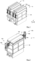
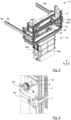
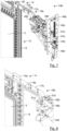
- a conveying system for use with a processing apparatus comprising a plurality of processing stations 1a,b of a first type ( Figs. 1 , 3 , 10-12 and 14 ) and at least one processing station 2 of a second type ( Figs. 2 and 4-9 ) will be described using the example of a vertical wet processing apparatus for planar substrates 3.
- the conveying system may, however, also be used in conjunction with other types of processing apparatus comprising a plurality of processing stations 1a,b arranged in a row and open at the top to allow a substrate 3 to be raised and lowered into the processing station 1a,b.
- treatment of the substrate 3 in the apparatus may include at least one of chemical or electrolytic metal deposition, chemical or electrolytic etching and chemical or electrolytic cleaning.
- the apparatus is arranged to carry out electrolytic metal deposition, chemical etching and chemical cleaning, with each of these steps taking place in a dedicated processing station 1a,b.
- electrolytic metal deposition include galvanic deposition of copper or nickel onto a surface of a substrate 3.
- Variants of the apparatus may be arranged for processing planar substrates 3 having a circular or polygonal (e.g. square or rectangular) shape.
- the substrate 3 may be a film or a semiconductor wafer, for example.
- Such a wafer may in particular have a frame-like structure obtainable by means of a so-called TAIKO process.
- a substrate 3 in the shape of a board is shown.
- the apparatus can be used to form electrically conductive traces on and/or or through the board, for example.
- the apparatus is a vertical plating apparatus, meaning that the substrate 3 is held in a generally vertical orientation during processing.
- the processing stations 1a,b,2 can thus have a relatively large width, corresponding to their dimension in y-direction, and a shorter length, corresponding to their dimension in x-direction.
- a conveying system comprising a transporter 4 moves the substrate 3 from processing station 1a,b,2 to processing station 1a,b,2.
- the transporter 4 comprises a transporter frame 5.
- Transporter guide rails 6a,b ( Fig. 3 ) extending in the direction of the x-axis are arranged to carry travellers 7 ( Fig. 4 ) mounted on the transporter 4, more specifically the transporter frame 5.
- Racks 8a,b extend in the direction of the x-axis on either side of the transporter 4.
- Pinions 9 ( Fig. 4 ) are provided at the ends of axles 10 driven by a motor 11 ( Fig. 3 ) comprised in the transporter 4.
- the transporter 4 is thus arranged for linear motion in either direction along the x-axis.
- a coupler shoe (not shown in detail) on the transporter 4 forms part of a system for inductive power transfer to the transporter 4. This electrical power is used by the various actuators comprised in the transporter 4.
- the substrate 3 is received in a substrate holder 12, so that the conveying system handles an object comprising the substrate 3 and the substrate holder 12. In this way, the conveying system need not repeatedly clamp and release the substrate 3. Damage to the substrate 3 is thereby avoided.
- the substrate holder 12 shown in the example comprises two essentially identically shaped planar holding parts pressed against opposing major surfaces of the substrate 3.
- a section 13 of the substrate holder 12 for receiving the substrate 3 engages the substrate 3 in a border region of each of the two major surfaces of the substrate 3 along the entire perimeter of the substrate 3.
- the substrate holder 12 leaves a central region of each major surface exposed.
- the substrate holder 12 thus frames the substrate 3 on each side of the substrate 3. It is possible to use a substrate holder 12 that completely covers one of the two major surfaces of the substrate 3 instead, depending on the intended application.
- the substrate holder 12 further comprises a support part, in this case a support assembly 14 provided with features for engaging the substrate holder 12.
- the support assembly 14 in this example comprises two parallel bars 15a,b. These bars 15a,b extend essentially in a plane of the substrate holder 12.
- the support assembly 14 projects laterally in opposite directions with respect to the substrate holding parts between which the substrate 3 is held.
- Engagement features are provided on the projecting sections of the support assembly 14 for engaging the support assembly 14 on either side of the substrate 3 from a direction in which the substrate 3 extends relative to the support assembly 14.
- the engagement features comprise claws 16a,b ( Figs. 7-10 and 13-15 ) for receiving respective pins oriented with a longitudinal axis transverse to the plane of the substrate 3.
- the claws 16a,b are formed at the end of angled extensions 17 to the substrate holder support bars 15a,b.
- the claws 16a,b or similar recesses may be formed directly in an underside of the support bars 15.
- An end section 18 ( Fig. 13 ) extends in a same direction relative to the substrate holder support bars 15a,b as the section 13 for receiving the substrate 3.
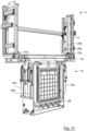
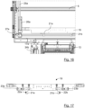
- the transporter 4 comprises a holding component 19 ( Figs. 11 , 12 and 14-17 ) for releasably holding the substrate holder 12.
- the holding component 19 has a relatively elongated shape.
- the holding component 19 extends essentially in y-direction, i.e. transverse to the direction of movement of the transporter 4 past the processing stations 1a,b,2.
- the substrate holder 12 is provided with further engagement features for interlocking engagement with co-operating engagement features of the holding component 19.
- the engagement features of the substrate holder 12 are provided at two distinct locations along the substrate holder support bars 15a,b. This essentially precludes any rotation of the substrate holder 12 about the z-axis during handling by the conveying system. Provision of the engagement features at two distinct locations also helps prevent any swinging of the substrate holder 12 in a plane of the substrate 3. As a consequence, the engagement features - in this example the claws 16a,b - can be aligned relatively accurately when the substrate holder 12 is lowered into the processing station 1a,b.
- the engagement features of the substrate holder 12 comprise features behind which movable engagement features of the holding component 19 can hook to allow the engagement features to interlock.
- the engagement features of the substrate holder 12 comprise pins 20 extending between the substrate holder support bars 15a,b.
- the engagement features of the holding component 19 comprise hooks 21a,b ( Figs. 14-17 ) movably journalled to the holding component 19.
- the hooks 21a,b are open in opposite lateral directions ( Figs. 16 and 17 ).
- the hooks 21a,b are moved in opposite directions along the y-axis to engage the pins 20 by means of inside edge sections 22a,b ( Fig. 17 ) of the hooks 21a,b.
- the holding component 19 may comprise engagement features with a different shape in other embodiments, as long as they are movable in the y-direction to hook behind engagement features of the substrate holder 12. In this way, the substrate holder 12 is supported by the engagement features of the holding component 19 when suspended from the holding component 19.
- the holding component 19 is movable with respect to the transporter frame 5 in z-direction.
- the transporter frame 4 functions as a support part of the transporter 4.
- a pair of carriers 24a,b ( Fig. 12 ) is guided for linear movement with respect to the transporter frame 5, the holding component 19 is coupled to the carriers 24a,b and held between the carriers 24a,b.
- the transporter 4 comprises two lifting devices comprising respective actuators for moving the carriers 24a,b, and thus the holding component 19, in the z-direction. Operation of the actuators is synchronised. In an alternative embodiment, only one actuator is provided and the other carrier 24a,b is merely moved along its guide by the holding component 19.
- the actuators may be electro-mechanical actuators, for example. Pneumatic or hydraulic actuators are also possible in principle, but require space for a piston. Linear actuators employing a motor and screw mechanism are relatively well-suited.
- the illustrated example makes use of a lead screw 25a,b having an axis of rotation extending essentially in the z-direction and rotatably journalled on the transporter frame 5.
- Rotary motors 26a,b are arranged to drive the lead screws 25a,b via transmission mechanisms 27a,b.
- the lead screws 25a,b guide movement of the carriers 24a,b, which travel along the lead screws 25a,b.
- the motors 26a,b thus remain stationary with respect to the transporter 4.
- linear actuator With this type of linear actuator, the longest element of the mechanism, namely the lead screw 25a,b is not displaced in z-direction.
- Alternatives with a similar effect include linear actuators comprising a mechanism comprising a rack and pinion, a belt drive or a winch.
- the carriers 24a,b need not comprise the electric motors, which are instead supported by the frame.
- the paths of movement of the holding component carriers 24a,b terminate at ends proximal to the processing stations 1a,b,2 , which ends are at a level (with respect to the z-axis) higher than that of a lower limit of the transporter 4, in this case of the transporter frame 5. Distal ends of the paths of movement of the holding component carriers 24a,b are at such a level that the path of movement of the holding component 19 terminates with the holding component 19 retained within the confines of the transporter 4, in this example as determined by the transporter frame 5.
- This level and the distance from the lower edge of the substrate holder to the distal side of the holding component 19 are sufficient for the substrate holder 12 to be maintained clear of the processing apparatus as the transporter 4 moves from processing station 1a,b,2 to processing station 1a,b,2.
- the maximum dimension of the holding component 19 is insufficient to insert the substrate holder 12 completely into at least one of the processing stations 1a,b,2.
- the end point of the movement path of the holding component 19 proximal to the processing stations 1a,b,2 corresponds to a transfer position of the substrate holder 12.
- the processing stations 1a,b of a first type are for processes in which the substrate remains stationary.
- An example would be a rinsing process.
- the processing station 1a comprises an outer casing 28 and two inner receptacles 29 for forming baths for receiving at least the substrate holder section 13 in which the substrate 3 is received.
- Top slits 30a,b ( Fig. 1 ) are defined at the top of the processing station 1a, through which the substrate holder 12 can pass when oriented with its plane essentially parallel to the direction of movement.
- the top slits 30a,b are too narrow to permit entry of the holding component 19.
- a further cover 31 is arranged over the processing stations 1a,b.
- the cover 31 determines the height above which the transporter 4 and the lower edge of the substrate holder 12 are held when the transporter 4 moves past the processing stations 1a,b,2.
- the cover 31 is provided with cover slits 32 aligned with the top slits 30a,b.
- the cover slits 32 are dimensioned to allow the substrate holder 12 to pass through them.
- the cover slits 32 are surrounded on all sides by the cover 31, so that the holding component 19 is unable to pass through the cover slits 32.
- the receptacles 29 and casing 28 are provided with side walls that leave open side wall slits 33a,b extending from a mouth of the receptacle 29a,b concerned.
- the side wall slits 33a,b ( Fig. 12 ) are provided in pairs, the members of which are aligned and located on opposite sides of the receptacle 29a,b.
- the dimensions of the side wall slits 33a,b are sufficient to allow the carrier bar extensions 17 of the substrate holder 12 to pass through the side wall slits 33a,b.
- the object movement devices of the processing stations 1a,b of the first type comprise only linear actuators 34a-d. These permit only movement of the substrate holder 12 in the z-direction, i.e. along the path of movement into and out of the processing station 1a.
- the linear actuators 34a-d may be pneumatic, hydraulic or electromechanical linear actuators 34a-d, for example.
- the linear actuators 34a-d comprise a piston 35 ( Fig. 14 ), at a free end of which a holding pin 36 is arranged.
- the holding pin 36 is configured for engaging one of the claws 16a,b of the substrate holder.
- the holding pin 36 is provided with holding pin discs 37 presenting respective opposing surfaces between which the claw 16a,b is inserted.
- the engagement between the holding pin 36 and claw 16a,b prevents relative movement in x- and y-direction. In z-direction, the holding pin 36 and claw 16a,b are held in engagement only through the force of gravity.
- the processing station 2 of a second type is for processes in which the substrate 3 is moved during processing.
- An example would be a plating process.
- the movement is in the plane of the substrate 3.
- the movement complements or replaces agitation of the fluid in which the substrate 3 is submerged for processing.
- An example of the kind of movement contemplated, and a description of its effects, is provided in WO 2017/093382 A1 .
- the processing station 2 comprises an outer casing 38 and an inner receptacle 39 ( Figs. 5,6 ) for forming a bath for receiving at least the substrate holder section 13 in which the substrate 3 is received.
- Two removable cover parts 40a,b ( Fig. 2 ) close most of the mouth defined by the outer casing 38 and inner receptacle 39.
- a top slit 41 is defined between the cover parts 40a,b.
- the substrate holder 12 is able to pass through the top slit 41 when oriented with its plane essentially parallel to the direction of movement.
- the top slits 41 is too narrow to permit entry of the holding component 19, however.
- the receptacle 39 and casing 38 are provided with side walls that leave open side wall slits 42a,b ( Figs. 5,6 ) extending from a mouth of the receptacle 39 or casing 38.
- the side wall slits 42a,b are provided in pairs, the members of which are aligned and located on opposite sides of the receptacle 39 and casing 38.
- the dimensions of the side wall slits 42a,b are sufficient to allow the carrier bar extensions 17 of the substrate holder 12 to pass through the side wall slits 33a,b.
- a pair of object movement devices 43a,b is associated with the processing station 2.
- Each object movement device 43a,b comprises a carrier part support 44a,b and a linear actuator for moving the carrier part support 44a,b in the z-direction.
- the linear actuators comprise screw drives, each comprising a rotating lead screw 45a,b driven by a stationary rotary motor 46a,b and a traveller 47a,b coupled to the carrier part support 44a,b.
- Carrier part support guides 48a,b support and guide the movement of the carrier part supports 44a,b. This type of linear actuator allows for relatively precise positioning in z-direction, so that movement of the substrate holder 12 within a small range during processing can be controlled relatively accurately.
- the lead screws 45a,b and carrier part support guides 48a,b are long enough to enable the substrate holder 12 also to be moved to the transfer position.
- the carrier part supports 44a,b support carrier parts 49a,b provided with respective holding pins 50a,b ( Figs. 7-10 ) for engaging the claws 16a,b of the substrate holder 12.
- Each holding pin 50 is provided with holding pin discs 51 presenting respective opposing surfaces between which the claw 16a,b is inserted.
- the engagement between the holding pin 50 and claw 16a,b prevents relative movement in x- and y-direction. In z-direction, the holding pin 50 and claw 16a,b are held in engagement only through the force of gravity.
- the holding pins 50 are electrically conducting and connected to power supplies (not shown).
- the holding pin discs 51 are electrically insulating.
- the carrier parts 49a,b are movably journalled on the carrier part supports 44a,b such as to permit only movement in the y-direction.
- Actuators 52a,b ( Figs. 7 and 10 ) are provided to drive the movement.
- the operation of the object movement devices 43a,b responsible for moving the substrate holder 12 in y- and z-direction within the processing station 2 is synchronised.
- Figs. 9 and 10 show the end positions of the carrier part 49a driven by the actuator 52a.
- the object movement devices 43a,b of the processing station 2 of the second type are arranged to lift the substrate holder 12 to the transfer position, where the holding component 19 engages the substrate holder 12 to lift the substrate holder 12 further out of the processing station 2.
- the holding component 19 can have a relatively low height and short path of movement relative to the transporter 4.
- the transporter 4 can thus have a relatively low height, so that the processing apparatus with the conveying system can be placed in a hall with a relatively low ceiling.
Landscapes
- Container, Conveyance, Adherence, Positioning, Of Wafer (AREA)
Priority Applications (2)
| Application Number | Priority Date | Filing Date | Title |
|---|---|---|---|
| EP19184721.9A EP3761348B1 (en) | 2019-07-05 | 2019-07-05 | System for conveying a substrate between processing stations of a processing apparatus, processing apparatus and methods of handling a substrate |
| PT191847219T PT3761348T (pt) | 2019-07-05 | 2019-07-05 | Sistema para transportar um substrato entre estações de processamento de um aparelho de processamento, aparelho de processamento e métodos de manusear um substrato |
Applications Claiming Priority (1)
| Application Number | Priority Date | Filing Date | Title |
|---|---|---|---|
| EP19184721.9A EP3761348B1 (en) | 2019-07-05 | 2019-07-05 | System for conveying a substrate between processing stations of a processing apparatus, processing apparatus and methods of handling a substrate |
Publications (2)
| Publication Number | Publication Date |
|---|---|
| EP3761348A1 EP3761348A1 (en) | 2021-01-06 |
| EP3761348B1 true EP3761348B1 (en) | 2024-03-27 |
Family
ID=67437605
Family Applications (1)
| Application Number | Title | Priority Date | Filing Date |
|---|---|---|---|
| EP19184721.9A Active EP3761348B1 (en) | 2019-07-05 | 2019-07-05 | System for conveying a substrate between processing stations of a processing apparatus, processing apparatus and methods of handling a substrate |
Country Status (2)
| Country | Link |
|---|---|
| EP (1) | EP3761348B1 (pt) |
| PT (1) | PT3761348T (pt) |
Family Cites Families (5)
| Publication number | Priority date | Publication date | Assignee | Title |
|---|---|---|---|---|
| JP6077886B2 (ja) * | 2013-03-04 | 2017-02-08 | 株式会社荏原製作所 | めっき装置 |
| US9388504B2 (en) * | 2013-03-26 | 2016-07-12 | Ebara Corporation | Plating apparatus and plating method |
| TW201502315A (zh) * | 2013-07-10 | 2015-01-16 | 荏原製作所股份有限公司 | 濕式處理裝置及鍍覆裝置 |
| EP3176288A1 (en) | 2015-12-03 | 2017-06-07 | ATOTECH Deutschland GmbH | Method for galvanic metal deposition |
| JP6878056B2 (ja) * | 2017-03-14 | 2021-05-26 | 株式会社荏原製作所 | めっき方法 |
-
2019
- 2019-07-05 EP EP19184721.9A patent/EP3761348B1/en active Active
- 2019-07-05 PT PT191847219T patent/PT3761348T/pt unknown
Also Published As
| Publication number | Publication date |
|---|---|
| PT3761348T (pt) | 2024-07-02 |
| EP3761348A1 (en) | 2021-01-06 |
Similar Documents
| Publication | Publication Date | Title |
|---|---|---|
| EP3758049B1 (en) | Device and method for moving an object into a processing station, conveying system and processing apparatus | |
| KR100989279B1 (ko) | 기판처리장치 | |
| TWI564988B (zh) | 平行且單一的基板處理系統 | |
| EP2162569B1 (en) | Vertical system for the plating treatment of a work piece and method for conveying the work piece | |
| KR102103806B1 (ko) | 기판 처리 장치 및 기판 반송 방법 | |
| KR20120029325A (ko) | 반송 장치 | |
| KR20150141130A (ko) | 기판 홀더용의 기판 착탈부, 이것을 구비한 습식 기판 처리 장치, 기판 처리 장치 및 기판 반송 방법 | |
| ES2339064T3 (es) | Sistema de decapado de catodos. | |
| DE994355T1 (de) | Vorrichtung zur Verarbeitung von Assayproben | |
| US20130055954A1 (en) | Integrated semiconductor-processing apparatus | |
| JP2019026863A (ja) | ワーク保持治具及び電気めっき装置 | |
| JP2020066499A (ja) | 搬送システム | |
| CN105428284B (zh) | 引线框架的处理产线 | |
| KR20180066192A (ko) | 진공 처리 장치 | |
| CN112242320B (zh) | 衬底处理装置及衬底搬送方法 | |
| JP4137244B2 (ja) | 基板洗浄装置における搬送機構 | |
| KR101863475B1 (ko) | 기판 반송 시스템 및 방법 | |
| US20150013905A1 (en) | Wet processing apparatus and plating apparatus | |
| EP3761348A1 (en) | System for conveying a substrate between processing stations of a processing apparatus, processing apparatus and methods of handling a substrate | |
| KR102248738B1 (ko) | 캐리어를 상승 또는 하강시키기 위한 조립체, 진공 챔버에서 캐리어를 운송하기 위한 장치, 및 캐리어를 상승 또는 하강시키기 위한 방법 | |
| KR101593742B1 (ko) | 기판 처리 장치 | |
| KR101768519B1 (ko) | 기판 처리 설비 | |
| KR100898044B1 (ko) | 스토커 유닛 및 상기 스토커 유닛의 카세트 처리 방법,그리고 이를 구비하는 기판 처리 장치 | |
| KR102297135B1 (ko) | 도금 장치 | |
| EP2975638A1 (en) | Processing apparatus for processing a semiconductor ingot, carrier and method of transferring and processing a semiconductor ingot |
Legal Events
| Date | Code | Title | Description |
|---|---|---|---|
| PUAI | Public reference made under article 153(3) epc to a published international application that has entered the european phase |
Free format text: ORIGINAL CODE: 0009012 |
|
| STAA | Information on the status of an ep patent application or granted ep patent |
Free format text: STATUS: THE APPLICATION HAS BEEN PUBLISHED |
|
| AK | Designated contracting states |
Kind code of ref document: A1 Designated state(s): AL AT BE BG CH CY CZ DE DK EE ES FI FR GB GR HR HU IE IS IT LI LT LU LV MC MK MT NL NO PL PT RO RS SE SI SK SM TR |
|
| AX | Request for extension of the european patent |
Extension state: BA ME |
|
| STAA | Information on the status of an ep patent application or granted ep patent |
Free format text: STATUS: REQUEST FOR EXAMINATION WAS MADE |
|
| 17P | Request for examination filed |
Effective date: 20210630 |
|
| RBV | Designated contracting states (corrected) |
Designated state(s): AL AT BE BG CH CY CZ DE DK EE ES FI FR GB GR HR HU IE IS IT LI LT LU LV MC MK MT NL NO PL PT RO RS SE SI SK SM TR |
|
| RAP3 | Party data changed (applicant data changed or rights of an application transferred) |
Owner name: ATOTECH DEUTSCHLAND GMBH & CO. KG |
|
| STAA | Information on the status of an ep patent application or granted ep patent |
Free format text: STATUS: EXAMINATION IS IN PROGRESS |
|
| 17Q | First examination report despatched |
Effective date: 20221019 |
|
| GRAP | Despatch of communication of intention to grant a patent |
Free format text: ORIGINAL CODE: EPIDOSNIGR1 |
|
| STAA | Information on the status of an ep patent application or granted ep patent |
Free format text: STATUS: GRANT OF PATENT IS INTENDED |
|
| INTG | Intention to grant announced |
Effective date: 20230519 |
|
| GRAJ | Information related to disapproval of communication of intention to grant by the applicant or resumption of examination proceedings by the epo deleted |
Free format text: ORIGINAL CODE: EPIDOSDIGR1 |
|
| STAA | Information on the status of an ep patent application or granted ep patent |
Free format text: STATUS: EXAMINATION IS IN PROGRESS |
|
| INTC | Intention to grant announced (deleted) | ||
| GRAP | Despatch of communication of intention to grant a patent |
Free format text: ORIGINAL CODE: EPIDOSNIGR1 |
|
| STAA | Information on the status of an ep patent application or granted ep patent |
Free format text: STATUS: GRANT OF PATENT IS INTENDED |
|
| INTG | Intention to grant announced |
Effective date: 20231023 |
|
| RAP3 | Party data changed (applicant data changed or rights of an application transferred) |
Owner name: ATOTECH DEUTSCHLAND GMBH & CO. KG |
|
| GRAS | Grant fee paid |
Free format text: ORIGINAL CODE: EPIDOSNIGR3 |
|
| GRAA | (expected) grant |
Free format text: ORIGINAL CODE: 0009210 |
|
| STAA | Information on the status of an ep patent application or granted ep patent |
Free format text: STATUS: THE PATENT HAS BEEN GRANTED |
|
| AK | Designated contracting states |
Kind code of ref document: B1 Designated state(s): AL AT BE BG CH CY CZ DE DK EE ES FI FR GB GR HR HU IE IS IT LI LT LU LV MC MK MT NL NO PL PT RO RS SE SI SK SM TR |
|
| REG | Reference to a national code |
Ref country code: GB Ref legal event code: FG4D |
|
| REG | Reference to a national code |
Ref country code: CH Ref legal event code: EP |
|
| REG | Reference to a national code |
Ref country code: DE Ref legal event code: R096 Ref document number: 602019048899 Country of ref document: DE |
|
| REG | Reference to a national code |
Ref country code: IE Ref legal event code: FG4D |
|
| REG | Reference to a national code |
Ref country code: PT Ref legal event code: SC4A Ref document number: 3761348 Country of ref document: PT Date of ref document: 20240702 Kind code of ref document: T Free format text: AVAILABILITY OF NATIONAL TRANSLATION Effective date: 20240626 |
|
| PG25 | Lapsed in a contracting state [announced via postgrant information from national office to epo] |
Ref country code: LT Free format text: LAPSE BECAUSE OF FAILURE TO SUBMIT A TRANSLATION OF THE DESCRIPTION OR TO PAY THE FEE WITHIN THE PRESCRIBED TIME-LIMIT Effective date: 20240327 |
|
| REG | Reference to a national code |
Ref country code: LT Ref legal event code: MG9D |
|
| PG25 | Lapsed in a contracting state [announced via postgrant information from national office to epo] |
Ref country code: GR Free format text: LAPSE BECAUSE OF FAILURE TO SUBMIT A TRANSLATION OF THE DESCRIPTION OR TO PAY THE FEE WITHIN THE PRESCRIBED TIME-LIMIT Effective date: 20240628 |
|
| PG25 | Lapsed in a contracting state [announced via postgrant information from national office to epo] |
Ref country code: RS Free format text: LAPSE BECAUSE OF FAILURE TO SUBMIT A TRANSLATION OF THE DESCRIPTION OR TO PAY THE FEE WITHIN THE PRESCRIBED TIME-LIMIT Effective date: 20240627 Ref country code: HR Free format text: LAPSE BECAUSE OF FAILURE TO SUBMIT A TRANSLATION OF THE DESCRIPTION OR TO PAY THE FEE WITHIN THE PRESCRIBED TIME-LIMIT Effective date: 20240327 |
|
| PG25 | Lapsed in a contracting state [announced via postgrant information from national office to epo] |
Ref country code: RS Free format text: LAPSE BECAUSE OF FAILURE TO SUBMIT A TRANSLATION OF THE DESCRIPTION OR TO PAY THE FEE WITHIN THE PRESCRIBED TIME-LIMIT Effective date: 20240627 Ref country code: NO Free format text: LAPSE BECAUSE OF FAILURE TO SUBMIT A TRANSLATION OF THE DESCRIPTION OR TO PAY THE FEE WITHIN THE PRESCRIBED TIME-LIMIT Effective date: 20240627 Ref country code: LT Free format text: LAPSE BECAUSE OF FAILURE TO SUBMIT A TRANSLATION OF THE DESCRIPTION OR TO PAY THE FEE WITHIN THE PRESCRIBED TIME-LIMIT Effective date: 20240327 Ref country code: HR Free format text: LAPSE BECAUSE OF FAILURE TO SUBMIT A TRANSLATION OF THE DESCRIPTION OR TO PAY THE FEE WITHIN THE PRESCRIBED TIME-LIMIT Effective date: 20240327 Ref country code: GR Free format text: LAPSE BECAUSE OF FAILURE TO SUBMIT A TRANSLATION OF THE DESCRIPTION OR TO PAY THE FEE WITHIN THE PRESCRIBED TIME-LIMIT Effective date: 20240628 Ref country code: FI Free format text: LAPSE BECAUSE OF FAILURE TO SUBMIT A TRANSLATION OF THE DESCRIPTION OR TO PAY THE FEE WITHIN THE PRESCRIBED TIME-LIMIT Effective date: 20240327 Ref country code: BG Free format text: LAPSE BECAUSE OF FAILURE TO SUBMIT A TRANSLATION OF THE DESCRIPTION OR TO PAY THE FEE WITHIN THE PRESCRIBED TIME-LIMIT Effective date: 20240327 |
|
| REG | Reference to a national code |
Ref country code: NL Ref legal event code: MP Effective date: 20240327 |
|
| PG25 | Lapsed in a contracting state [announced via postgrant information from national office to epo] |
Ref country code: SE Free format text: LAPSE BECAUSE OF FAILURE TO SUBMIT A TRANSLATION OF THE DESCRIPTION OR TO PAY THE FEE WITHIN THE PRESCRIBED TIME-LIMIT Effective date: 20240327 Ref country code: LV Free format text: LAPSE BECAUSE OF FAILURE TO SUBMIT A TRANSLATION OF THE DESCRIPTION OR TO PAY THE FEE WITHIN THE PRESCRIBED TIME-LIMIT Effective date: 20240327 |
|
| PG25 | Lapsed in a contracting state [announced via postgrant information from national office to epo] |
Ref country code: NL Free format text: LAPSE BECAUSE OF FAILURE TO SUBMIT A TRANSLATION OF THE DESCRIPTION OR TO PAY THE FEE WITHIN THE PRESCRIBED TIME-LIMIT Effective date: 20240327 |
|
| REG | Reference to a national code |
Ref country code: AT Ref legal event code: UEP Ref document number: 1670751 Country of ref document: AT Kind code of ref document: T Effective date: 20240327 |
|
| PG25 | Lapsed in a contracting state [announced via postgrant information from national office to epo] |
Ref country code: NL Free format text: LAPSE BECAUSE OF FAILURE TO SUBMIT A TRANSLATION OF THE DESCRIPTION OR TO PAY THE FEE WITHIN THE PRESCRIBED TIME-LIMIT Effective date: 20240327 |
|
| PG25 | Lapsed in a contracting state [announced via postgrant information from national office to epo] |
Ref country code: IS Free format text: LAPSE BECAUSE OF FAILURE TO SUBMIT A TRANSLATION OF THE DESCRIPTION OR TO PAY THE FEE WITHIN THE PRESCRIBED TIME-LIMIT Effective date: 20240727 |
|
| PG25 | Lapsed in a contracting state [announced via postgrant information from national office to epo] |
Ref country code: SM Free format text: LAPSE BECAUSE OF FAILURE TO SUBMIT A TRANSLATION OF THE DESCRIPTION OR TO PAY THE FEE WITHIN THE PRESCRIBED TIME-LIMIT Effective date: 20240327 |
|
| PG25 | Lapsed in a contracting state [announced via postgrant information from national office to epo] |
Ref country code: ES Free format text: LAPSE BECAUSE OF FAILURE TO SUBMIT A TRANSLATION OF THE DESCRIPTION OR TO PAY THE FEE WITHIN THE PRESCRIBED TIME-LIMIT Effective date: 20240327 |
|
| PG25 | Lapsed in a contracting state [announced via postgrant information from national office to epo] |
Ref country code: CZ Free format text: LAPSE BECAUSE OF FAILURE TO SUBMIT A TRANSLATION OF THE DESCRIPTION OR TO PAY THE FEE WITHIN THE PRESCRIBED TIME-LIMIT Effective date: 20240327 Ref country code: EE Free format text: LAPSE BECAUSE OF FAILURE TO SUBMIT A TRANSLATION OF THE DESCRIPTION OR TO PAY THE FEE WITHIN THE PRESCRIBED TIME-LIMIT Effective date: 20240327 |
|
| PG25 | Lapsed in a contracting state [announced via postgrant information from national office to epo] |
Ref country code: PL Free format text: LAPSE BECAUSE OF FAILURE TO SUBMIT A TRANSLATION OF THE DESCRIPTION OR TO PAY THE FEE WITHIN THE PRESCRIBED TIME-LIMIT Effective date: 20240327 |
|
| PG25 | Lapsed in a contracting state [announced via postgrant information from national office to epo] |
Ref country code: SK Free format text: LAPSE BECAUSE OF FAILURE TO SUBMIT A TRANSLATION OF THE DESCRIPTION OR TO PAY THE FEE WITHIN THE PRESCRIBED TIME-LIMIT Effective date: 20240327 |
|
| PG25 | Lapsed in a contracting state [announced via postgrant information from national office to epo] |
Ref country code: SM Free format text: LAPSE BECAUSE OF FAILURE TO SUBMIT A TRANSLATION OF THE DESCRIPTION OR TO PAY THE FEE WITHIN THE PRESCRIBED TIME-LIMIT Effective date: 20240327 Ref country code: SK Free format text: LAPSE BECAUSE OF FAILURE TO SUBMIT A TRANSLATION OF THE DESCRIPTION OR TO PAY THE FEE WITHIN THE PRESCRIBED TIME-LIMIT Effective date: 20240327 Ref country code: RO Free format text: LAPSE BECAUSE OF FAILURE TO SUBMIT A TRANSLATION OF THE DESCRIPTION OR TO PAY THE FEE WITHIN THE PRESCRIBED TIME-LIMIT Effective date: 20240327 Ref country code: PL Free format text: LAPSE BECAUSE OF FAILURE TO SUBMIT A TRANSLATION OF THE DESCRIPTION OR TO PAY THE FEE WITHIN THE PRESCRIBED TIME-LIMIT Effective date: 20240327 Ref country code: IS Free format text: LAPSE BECAUSE OF FAILURE TO SUBMIT A TRANSLATION OF THE DESCRIPTION OR TO PAY THE FEE WITHIN THE PRESCRIBED TIME-LIMIT Effective date: 20240727 Ref country code: ES Free format text: LAPSE BECAUSE OF FAILURE TO SUBMIT A TRANSLATION OF THE DESCRIPTION OR TO PAY THE FEE WITHIN THE PRESCRIBED TIME-LIMIT Effective date: 20240327 Ref country code: EE Free format text: LAPSE BECAUSE OF FAILURE TO SUBMIT A TRANSLATION OF THE DESCRIPTION OR TO PAY THE FEE WITHIN THE PRESCRIBED TIME-LIMIT Effective date: 20240327 Ref country code: CZ Free format text: LAPSE BECAUSE OF FAILURE TO SUBMIT A TRANSLATION OF THE DESCRIPTION OR TO PAY THE FEE WITHIN THE PRESCRIBED TIME-LIMIT Effective date: 20240327 |
|
| REG | Reference to a national code |
Ref country code: DE Ref legal event code: R097 Ref document number: 602019048899 Country of ref document: DE |
|
| PG25 | Lapsed in a contracting state [announced via postgrant information from national office to epo] |
Ref country code: DK Free format text: LAPSE BECAUSE OF FAILURE TO SUBMIT A TRANSLATION OF THE DESCRIPTION OR TO PAY THE FEE WITHIN THE PRESCRIBED TIME-LIMIT Effective date: 20240327 |
|
| PG25 | Lapsed in a contracting state [announced via postgrant information from national office to epo] |
Ref country code: DK Free format text: LAPSE BECAUSE OF FAILURE TO SUBMIT A TRANSLATION OF THE DESCRIPTION OR TO PAY THE FEE WITHIN THE PRESCRIBED TIME-LIMIT Effective date: 20240327 |
|
| PG25 | Lapsed in a contracting state [announced via postgrant information from national office to epo] |
Ref country code: MC Free format text: LAPSE BECAUSE OF FAILURE TO SUBMIT A TRANSLATION OF THE DESCRIPTION OR TO PAY THE FEE WITHIN THE PRESCRIBED TIME-LIMIT Effective date: 20240327 |
|
| PLBE | No opposition filed within time limit |
Free format text: ORIGINAL CODE: 0009261 |
|
| STAA | Information on the status of an ep patent application or granted ep patent |
Free format text: STATUS: NO OPPOSITION FILED WITHIN TIME LIMIT |
|
| REG | Reference to a national code |
Ref country code: CH Ref legal event code: PL |
|
| 26N | No opposition filed |
Effective date: 20250103 |
|
| PG25 | Lapsed in a contracting state [announced via postgrant information from national office to epo] |
Ref country code: LU Free format text: LAPSE BECAUSE OF NON-PAYMENT OF DUE FEES Effective date: 20240705 |
|
| GBPC | Gb: european patent ceased through non-payment of renewal fee |
Effective date: 20240705 |
|
| PG25 | Lapsed in a contracting state [announced via postgrant information from national office to epo] |
Ref country code: LU Free format text: LAPSE BECAUSE OF NON-PAYMENT OF DUE FEES Effective date: 20240705 |
|
| PG25 | Lapsed in a contracting state [announced via postgrant information from national office to epo] |
Ref country code: SI Free format text: LAPSE BECAUSE OF FAILURE TO SUBMIT A TRANSLATION OF THE DESCRIPTION OR TO PAY THE FEE WITHIN THE PRESCRIBED TIME-LIMIT Effective date: 20240327 Ref country code: CH Free format text: LAPSE BECAUSE OF NON-PAYMENT OF DUE FEES Effective date: 20240731 Ref country code: BE Free format text: LAPSE BECAUSE OF NON-PAYMENT OF DUE FEES Effective date: 20240731 |
|
| PG25 | Lapsed in a contracting state [announced via postgrant information from national office to epo] |
Ref country code: FR Free format text: LAPSE BECAUSE OF NON-PAYMENT OF DUE FEES Effective date: 20240731 |
|
| PG25 | Lapsed in a contracting state [announced via postgrant information from national office to epo] |
Ref country code: GB Free format text: LAPSE BECAUSE OF NON-PAYMENT OF DUE FEES Effective date: 20240705 |
|
| REG | Reference to a national code |
Ref country code: BE Ref legal event code: MM Effective date: 20240731 |
|
| PGFP | Annual fee paid to national office [announced via postgrant information from national office to epo] |
Ref country code: PT Payment date: 20250623 Year of fee payment: 7 |
|
| PG25 | Lapsed in a contracting state [announced via postgrant information from national office to epo] |
Ref country code: IE Free format text: LAPSE BECAUSE OF NON-PAYMENT OF DUE FEES Effective date: 20240705 |
|
| PGFP | Annual fee paid to national office [announced via postgrant information from national office to epo] |
Ref country code: DE Payment date: 20250728 Year of fee payment: 7 |
|
| PGFP | Annual fee paid to national office [announced via postgrant information from national office to epo] |
Ref country code: IT Payment date: 20250721 Year of fee payment: 7 |
|
| PGFP | Annual fee paid to national office [announced via postgrant information from national office to epo] |
Ref country code: AT Payment date: 20250718 Year of fee payment: 7 |
|
| PG25 | Lapsed in a contracting state [announced via postgrant information from national office to epo] |
Ref country code: CY Free format text: LAPSE BECAUSE OF FAILURE TO SUBMIT A TRANSLATION OF THE DESCRIPTION OR TO PAY THE FEE WITHIN THE PRESCRIBED TIME-LIMIT; INVALID AB INITIO Effective date: 20190705 |
|
| REG | Reference to a national code |
Ref country code: DE Ref legal event code: R079 Ref document number: 602019048899 Country of ref document: DE Free format text: PREVIOUS MAIN CLASS: H01L0021670000 Ipc: H10P0072000000 |
|
| PG25 | Lapsed in a contracting state [announced via postgrant information from national office to epo] |
Ref country code: HU Free format text: LAPSE BECAUSE OF FAILURE TO SUBMIT A TRANSLATION OF THE DESCRIPTION OR TO PAY THE FEE WITHIN THE PRESCRIBED TIME-LIMIT; INVALID AB INITIO Effective date: 20190705 |