EP3761459B1 - Rotationssteckverbinder - Google Patents
Rotationssteckverbinder Download PDFInfo
- Publication number
- EP3761459B1 EP3761459B1 EP19776607.4A EP19776607A EP3761459B1 EP 3761459 B1 EP3761459 B1 EP 3761459B1 EP 19776607 A EP19776607 A EP 19776607A EP 3761459 B1 EP3761459 B1 EP 3761459B1
- Authority
- EP
- European Patent Office
- Prior art keywords
- fixed body
- connector device
- space
- rotary connector
- cable
- Prior art date
- Legal status (The legal status is an assumption and is not a legal conclusion. Google has not performed a legal analysis and makes no representation as to the accuracy of the status listed.)
- Active
Links
Images


Classifications
-
- H—ELECTRICITY
- H01—ELECTRIC ELEMENTS
- H01R—ELECTRICALLY-CONDUCTIVE CONNECTIONS; STRUCTURAL ASSOCIATIONS OF A PLURALITY OF MUTUALLY-INSULATED ELECTRICAL CONNECTING ELEMENTS; COUPLING DEVICES; CURRENT COLLECTORS
- H01R35/00—Flexible or turnable line connectors, i.e. the rotation angle being limited
- H01R35/04—Turnable line connectors with limited rotation angle with frictional contact members
-
- H—ELECTRICITY
- H01—ELECTRIC ELEMENTS
- H01R—ELECTRICALLY-CONDUCTIVE CONNECTIONS; STRUCTURAL ASSOCIATIONS OF A PLURALITY OF MUTUALLY-INSULATED ELECTRICAL CONNECTING ELEMENTS; COUPLING DEVICES; CURRENT COLLECTORS
- H01R13/00—Details of coupling devices of the kinds covered by groups H01R12/70 or H01R24/00 - H01R33/00
- H01R13/46—Bases; Cases
- H01R13/52—Dustproof, splashproof, drip-proof, waterproof, or flameproof cases
-
- H—ELECTRICITY
- H01—ELECTRIC ELEMENTS
- H01R—ELECTRICALLY-CONDUCTIVE CONNECTIONS; STRUCTURAL ASSOCIATIONS OF A PLURALITY OF MUTUALLY-INSULATED ELECTRICAL CONNECTING ELEMENTS; COUPLING DEVICES; CURRENT COLLECTORS
- H01R35/00—Flexible or turnable line connectors, i.e. the rotation angle being limited
- H01R35/02—Flexible line connectors without frictional contact members
- H01R35/025—Flexible line connectors without frictional contact members having a flexible conductor wound around a rotation axis
-
- H—ELECTRICITY
- H01—ELECTRIC ELEMENTS
- H01R—ELECTRICALLY-CONDUCTIVE CONNECTIONS; STRUCTURAL ASSOCIATIONS OF A PLURALITY OF MUTUALLY-INSULATED ELECTRICAL CONNECTING ELEMENTS; COUPLING DEVICES; CURRENT COLLECTORS
- H01R13/00—Details of coupling devices of the kinds covered by groups H01R12/70 or H01R24/00 - H01R33/00
- H01R13/66—Structural association with built-in electrical component
- H01R13/68—Structural association with built-in electrical component with built-in fuse
- H01R13/684—Structural association with built-in electrical component with built-in fuse the fuse being removable
- H01R13/688—Structural association with built-in electrical component with built-in fuse the fuse being removable with housing part adapted for accessing the fuse
Definitions
- the technology disclosed in the present application relates to a rotary connector device.
- a known rotary connector device includes a fixed body, a rotation body rotatably attached to the fixed body, a fixed body-side connector, and a rotation body-side connector (for example, see WO 2017/221820 A1 ).
- the rotary connector device disclosed in WO 2017/221820 A1 further includes a cable conductor wire that is housed in a space between the fixed body and the rotation body and that electrically connects the fixed body-side connector and the rotation body-side connector.
- the fixed body disclosed in WO 2017/221820 A1 is a stator main body and a sub-stator that are coupled together to form a space therebetween.
- WO 2017/170752 A1 shows a rotary connector device according to the preamble of claim 1.
- an object of the technology disclosed in the present application is to increase the environmental resistance of a rotary connector device.
- the invention provides a rotary connector device according to claim 1, wherein the foreign matter is, for example, fluid water and dust so that the rotary connector device prevents foreign matter from entering the space.
- the environmental resistance of the rotary connector device is improved.
- the connection conductor is disposed on the fixed body in the second space, and the rotation body is connected to the second end of the cable conductor wire, foreign matter is prevented from adhering to the connection conductor, and thus deterioration of the connection conductor is inhibited.
- the inhibiting structure includes a protecting member configured to increase a length of a gap passageway between the coupling portion and the connection conductor, foreign matter is less likely to reach the connection conductor.
- the protecting member may be in contact with at least one of an inner surface of the first fixed body portion and an inner surface of the second fixed body portion at the coupling portion.
- the rotation body may be rotatable about a rotation axis along a first direction
- the coupling portion may be provided on an outer periphery of the fixed body when viewed in the first direction
- the protecting member may be disposed between the coupling portion and the connection conductor in a second direction substantially orthogonal to the first direction
- the protecting member may extend from the first fixed body portion or the second fixed body portion in the first direction. This configuration inhibits foreign matter from flowing around the protecting member extending in the first direction.
- the fixed body may include an engagement portion configured to engage the first fixed body portion and the second fixed body portion with each other, and the protecting member may be disposed between the engagement portion and the connection conductor in the second direction. Even in a case where foreign matter is likely to enter at the coupling portion in the vicinity of the engagement portion, the protecting member is disposed corresponding to the coupling portion at the position where foreign matter is likely to enter. Thus, this configuration can effectively inhibit the entry of foreign matter.
- a length of the protecting member in a third direction substantially orthogonal to the first direction and following the outer surface may be longer than a length of the engagement portion in the third direction. This configuration can prevent foreign matter from flowing around the protecting member that is long in the third direction even in a case where foreign matter enters from the coupling portion in the vicinity of the engagement portion.
- the engagement portion may include an engagement frame attached to one of the first fixed body portion and the second fixed body portion, and an engagement claw attached to the other of the first fixed body portion and the second fixed body portion. Even in a case where engagement between the engagement frame and the engagement claw is loosened, this configuration can effectively inhibit the entry of foreign matter because the protecting member is disposed at a position corresponding to the engagement portion.
- the protecting member may include an insulating material. This configuration can inhibit electrical connection problems such as short-circuiting even in a case where the protecting member is in contact with the connection conductor.
- the rotary connector device may include a first connector disposed outside the fixed body and including a terminal electrically connected to the connection conductor. This configuration improves connectivity between the rotary connector device and an external cable.
- the first connector may be partially disposed in the second space.
- the rotary connector device may include an insulating supporting body configured to support the connection conductor and attached to the fixed body in the space. This configuration can inhibit electrical connection problems such as short-circuiting of the connection conductor.
- the space includes a first space and a second space
- the rotation body is disposed corresponding to the first space
- the connection conductor is disposed in the second space.
- the cable includes the cable conductor wire, and an insulating covering member covering the cable conductor wire, the cable being disposed in a space between the rotation body and the fixed body.
- the inhibiting structure includes an inhibiting portion configured by the second fixed body portion covering the first fixed body portion in a radial direction of the rotation axis of the rotation body.
- a surface of the second fixed body portion may be in contact with an outer periphery of the first fixed body portion in the radial direction.
- the fixed body of the rotary connector device includes a first fixed body portion, a second fixed body portion disposed facing the first fixed body portion with the space being defined between the second fixed body portion and the first fixed body portion, and coupled to the first fixed body portion at a coupling portion, and an inhibiting structure configured to inhibit foreign matter from entering the space through the coupling portion.
- the coupling portion is exposed to outer surfaces of the first fixed body portion and the second fixed body portion, and the first fixed body portion and the second fixed body portion are connected to a rotation body rotatably assembled to the first fixed body portion and the second fixed body portion.
- This configuration inhibits the entry of foreign matter into the space, thereby improving the environmental resistance of the rotary connector device.
- the technology disclosed in the present application can enhance the environmental resistance of a rotary connector device.
- FIG. 1 is a perspective view of a rotary connector device 100 according to a first embodiment.
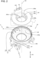
- FIG. 2 is an exploded perspective view of a fixed body 10 removed from a rotation body 20.
- the rotary connector device 100 includes the fixed body 10 and the rotation body 20.
- the rotation body 20 is assembled to the fixed body 10 so as to be rotatable about a rotation axis AX with respect to the fixed body 10.
- a first space S1 is defined between the fixed body 10 and the rotation body 20.
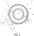
- FIG. 3 is a diagram illustrating an upper surface 10u of the fixed body 10 and for describing the arrangement of a cable 30 and a cable 32.
- the cable 30 and the cable 32 are disposed in the first space S1.
- a cable conductor wire 34 of the cable 30 (see FIGS. 4 and 7 ) has a first end connected to the fixed body 10 and a second end connected to the rotation body 20.
- the cable conductor wire 34 of the cable 32 has a first end connected to the fixed body 10 and a second end connected to the rotation body 20.
- the rotation body 20 can rotate about the rotation axis AX with respect to the fixed body 10.
- the number of cables provided in the rotary connector device 100 is not limited to two.
- the number of cables may be an even number, for example, four.
- the number of cables may be an odd number, for example, three.
- the rotary connector device 100 is used in, for example, a movable body (for example, an automobile) including a main body and a steering unit that is rotatable with respect to the main body.
- the fixed body 10 is attached to the main body of the movable body.
- the rotation body 20 is attached to the steering unit.
- the first end of the cable conductor wire 34 of the cable 30 and the first end of the cable conductor wire 34 of the cable 32 are electrically connected to an electronic device provided in the main body of the movable body.
- the second end of the cable conductor wire 34 of the cable 30 and the second end of the cable conductor wire 34 of the cable 32 are electrically connected to an electronic device (for example, a switch) provided in the steering unit.
- the rotary connector device 100 transmits/receives power or electrical signals to/from the electronic device provided in the main body of the movable body and the electronic device provided in the steering unit.
- the rotary connector device 100 may be used in a device other than a movable body.
- the fixed body 10 is provided with a first fixed body portion 12 and a second fixed body portion 14.
- the second fixed body portion 14 is coupled to the first fixed body portion 12 with the second fixed body portion 14 disposed above the first fixed body portion 12.
- the first fixed body portion 12 forms a bottom portion 10b of the fixed body 10.
- the second fixed body portion 14 forms a side wall 10l of the fixed body 10.
- the first fixed body portion 12 includes a first ring portion 120 and a first extending portion 122.
- the first ring portion 120 has a ring shape when the rotary connector device 100 is viewed in a first direction D1 along the rotation axis AX.
- the first ring portion 120 is disposed such that the rotation axis AX passes through the center of the first ring portion 120.
- the first extending portion 122 extends outward of an outer periphery 120a of the first ring portion 120 in the radial direction of the rotation axis AX.
- the second fixed body portion 14 includes an outer-circumferential cylindrical portion 140 and a second extending portion 142.
- the outer-circumferential cylindrical portion 140 is disposed such that a hollow portion 140a of the outer-circumferential cylindrical portion 140 extends in the first direction D1.
- the outer-circumferential cylindrical portion 140 extends upward from the outer periphery 120a of the first ring portion 120 in the first direction D1.
- the second extending portion 142 extends outward from the outer-circumferential cylindrical portion 140 in the radial direction of the rotation axis AX.
- the second extending portion 142 faces the first extending portion 122 in the first direction D1. Details of coupling between the first extending portion 122 and the second extending portion 142 are described later.
- the rotation body 20 includes a second ring portion 200 and an inner-circumferential cylindrical portion 202.
- the second ring portion 200 has a ring shape when the rotary connector device 100 is viewed in the first direction D1.
- the second ring portion 200 is disposed such that the rotation axis AX passes through the center of the second ring portion 200.
- the inner-circumferential cylindrical portion 202 is disposed such that a hollow portion 202a of the inner-circumferential cylindrical portion 202 extends in the first direction D1.
- the inner-circumferential cylindrical portion 202 extends downward from an inner periphery 200a of the second ring portion 200 in the first direction D1.
- the inner-circumferential cylindrical portion 202 is disposed inward of the outer-circumferential cylindrical portion 140 in the radial direction of the rotation axis AX.
- the first space S1 is defined by the first ring portion 120, the outer-circumferential cylindrical portion 140, the second ring portion 200, and the inner-circumferential cylindrical portion 202. That is, the first ring portion 120, the outer-circumferential cylindrical portion 140, the second ring portion 200, and the inner-circumferential cylindrical portion 202 face each other to define the first space S1.
- the first space S1 is equal to a space in which the hollow portion 202a of the inner-circumferential cylindrical portion 202 is excluded from the hollow portion 140a of the outer-circumferential cylindrical portion 140. Note that the first space S1 is included in a space S between the first fixed body portion 12 and the second fixed body portion 14.
- the inner-circumferential cylindrical portion 202 is engaged with an assembly member 90 (see FIG. 1 ).
- the assembly member 90 is disposed below the fixed body 10 in the first direction D1 and is rotatable about the rotation axis AX.
- the rotation body 20 is assembled to the fixed body 10 such that the rotation body 20 and the assembly member 90 sandwich the fixed body 10 in the first direction D1. Note that the assembly member 90 may be omitted.
- the inner-circumferential cylindrical portion 202 is provided in the rotation body 20.
- the inner-circumferential cylindrical portion 202 may be provided in the fixed body 10.
- the rotary connector device 100 has a shape including the hollow portion 202a, but the rotary connector device 100 need not include the hollow portion 202a.
- the rotary connector device 100 includes a first connector 40 and a second connector 42.
- the first connector 40 is connected to an external cable extending from the main body of a movable body, for example.
- the second connector 42 is connected to an external cable extending from the steering unit of a movable body, for example.
- the first connector 40 and the second connector 42 are electrically connected via the cable 30 and the cable 32.
- the first connector 40 is connected to the fixed body 10.
- the first connector 40 is disposed outward of the fixed body 10 in a direction orthogonal to the first direction D1.
- the first connector 40 may be located below the fixed body 10 or above the fixed body 10.
- the first connector 40 is disposed outside the space S.
- the first connector 40 may be partially disposed inside the space S.
- the first connector 40 includes a plurality of first terminals 400 and a first cover 402.
- the plurality of first terminals 400 are electrically connected to terminals of the external cable.
- the first cover 402 is connected to the first extending portion 122 and the second extending portion 142.
- the first cover 402 covers the plurality of first terminals 400 so as to open on a side opposite to the first extending portion 122 and the second extending portion 142 in a direction orthogonal to the rotation axis AX.
- the second connector 42 is disposed on the rotation body 20. However, the position of the second connector 42 is not limited to the position illustrated in FIG. 1 .
- the second connector 42 is connected to the rotation body 20.
- the second connector 42 includes a plurality of second terminals 420 and a second cover 422.
- the plurality of second terminals 420 are electrically connected to an external cable.
- the second cover 422 is connected to an upper surface 200b of the second ring portion 200.
- the second cover 422 covers the plurality of second terminals 420 such that an upper portion of the second cover 422 is open.
- the second connector 42 is disposed outside the space S. However, the second connector 42 may be partially disposed inside the space S.
- FIG. 4 is a perspective view of the cable 30 and the first connector 40 for describing connection between the cable 30 and the first connector 40.
- the first cover 402 is omitted from FIG. 4 .
- the cable 32 has substantially the same configuration as the cable 30, the cable 32 is also omitted from FIG. 4 .
- the cable 30 and the cable 32 each have a flat shape.
- the cable 30 and the cable 32 are both flexible.
- the cable 30 and the cable 32 each include a plurality of the cable conductor wires 34 and an insulating covering member 36 that covers the plurality of cable conductor wires 34.
- the cable 30 and the cable 32 are wound along the outer peripheral surface of the inner-circumferential cylindrical portion 202 and the inner peripheral surface of the outer-circumferential cylindrical portion 140 in the first space S1.
- the cable 30 and the cable 32 are both wound in a direction that reverses partway.
- the cable 30 passes through a hole formed in the outer-circumferential cylindrical portion 140 such that a first end of the cable 30 is located in a second space S2 (see FIG. 2 ) surrounded by the first extending portion 122 and the second extending portion 142.
- the cable 30 passes through a hole formed in the second ring portion 200 such that a second end of the cable 30 is located in a third space S3 (see FIG. 2 ) covered by the second cover 422.
- the rotary connector device 100 includes a plurality of connection conductors 50 and an insulating supporting body 54.
- the plurality of connection conductors 50 are provided for electrically connecting the plurality of cable conductor wires 34 of the cable 30 and the plurality of first terminals 400.
- the insulating supporting body 54 supports the plurality of connection conductors 50 and the plurality of first terminals 400 of the first connector 40.
- the insulating supporting body 54 is attached to at least one of the first extending portion 122 and the second extending portion 142 in the second space S2.
- Each of the plurality of connection conductors 50 is electrically connected to each of the plurality of first terminals 400. As illustrated in FIG. 4 , first ends of the plurality of cable conductor wires 34 of the cable 30 are connected to the plurality of connection conductors 50, respectively. The plurality of first ends of the plurality of cable conductor wires 34 and the plurality of connection conductors 50 are connected to each other by welding. However, the plurality of first ends of the plurality of cable conductor wires 34 and the plurality of connection conductors 50 may be connected to each other by a method other than welding. For example, the plurality of first ends of the plurality of cable conductor wires 34 and the plurality of connection conductors 50 may be crimped by using a cover member. Each of the plurality of first ends of the plurality of cable conductor wires 34 of the cable 32 are connected to each of the plurality of connection conductors 52 supported by an insulating supporting body 56 (see FIG. 7 ).
- Each of the plurality of second ends of the plurality of cable conductor wires 34 of the cable 30 is electrically connected to each of the plurality of second terminals 420 of the second connector 42.
- Each of the plurality of second ends of the cable conductor wires 34 of the cable 32 is electrically connected to each of the plurality of second terminals 420 of the second connector 42.
- connection conductors 50 and the number of cable conductor wires 34 are not limited to the example illustrated in FIG. 4 .
- the rotary connector device 100 may include only one connection conductor 50.
- the rotary connector device 100 may include only one cable conductor wire 34.
- FIG. 5 is a side view of the rotary connector device 100. As illustrated in FIG. 5 , the first fixed body portion 12 and the second fixed body portion 14 are coupled together at a coupling portion 16. The coupling portion 16 is exposed to an outer surface 10s of the fixed body 10.
- the outer surface 10s of the fixed body 10 is configured by the outer surfaces of at least the first ring portion 120, the outer-circumferential cylindrical portion 140, the first extending portion 122, and the second extending portion 142.
- the coupling portion 16 includes a first coupling portion 160 and a second coupling portion 162.
- the first extending portion 122 and the second extending portion 142 are coupled in the first direction D1.
- the first ring portion 120 and the outer-circumferential cylindrical portion 140 are coupled in the first direction D1.
- the fixed body 10 is provided with a plurality of engagement portions 18 that engage the first fixed body portion 12 with the second fixed body portion 14 while the first fixed body portion 12 and the second fixed body portion 14 are coupled.
- the plurality of engagement portions 18 are disposed along an outer periphery 10o of the fixed body 10 when the fixed body 10 is viewed in the first direction D1. In other words, the plurality of engagement portions 18 are disposed along the first coupling portion 160 and the second coupling portion 162 that are exposed to the outer surface 10s of the fixed body 10.
- the engagement portion 18 includes an engagement frame 180 and an engagement claw 188.
- the engagement frame 180 is attached to the first fixed body portion 12.
- the engagement claw 188 is attached to the second fixed body portion 14.
- the engagement frame 180 may be attached to the second fixed body portion 14, and the engagement claw 188 may be attached to the first fixed body portion 12.
- the engagement frame 180 includes a first frame piece 182, a second frame piece 184, and a connection piece 186.
- the first frame piece 182 and the second frame piece 184 each extend upward from the outer periphery 120a of the first ring portion 120 of the first fixed body portion 12 or the outer periphery of the first extending portion 122.
- the connection piece 186 extends in a direction orthogonal to the first direction D1 and along the outer periphery 10o, and connects an upper end of the first frame piece 182 and an upper end of the second frame piece 184.
- the engagement claw 188 is hooked on the connection piece 186 between the first frame piece 182 and the second frame piece 184.
- the engagement frame 180 is integrally formed with either the first ring portion 120 or the first extending portion 122.
- the engagement claw 188 is integrally formed with either the outer-circumferential cylindrical portion 140 or the second extending portion 142.
- the engagement portion 18 is not limited to the structure disclosed in the present embodiment. Furthermore, the plurality of engagement portions 18 may be omitted.
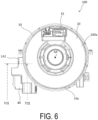
- FIG. 6 is a diagram illustrating a top surface 100u of the rotary connector device 100.
- FIG. 7 is a cross-sectional view of the rotary connector device 100 taken along the line VII-VII in FIG. 6 .
- the fixed body 10 includes a first wall 124, a second wall 144, and a third wall 146.
- the first wall 124, the second wall 144, and the third wall 146 define the second space S2.
- the second space S2 is included in the space S between the first fixed body portion 12 and the second fixed body portion 14.
- the second space S2 is also defined by the outer-circumferential cylindrical portion 140.
- the second space S2 may be defined without the outer-circumferential cylindrical portion 140.
- the first wall 124 extends outward from the outer periphery 120a of the first ring portion 120 in the radial direction of the rotation axis AX.
- the second wall 144 extends outward from the outer-circumferential cylindrical portion 140 in the radial direction of the rotation axis AX.
- the second wall 144 faces the first wall 124 in the first direction D1.
- the third wall 146 is parallel to the first direction D1 and is connected to the second wall 144.
- the third wall 146 extends to the first wall 124 in the first direction D1.
- the third wall 146 and the first wall 124 are coupled in the first direction D1.
- the first coupling portion 160 is exposed to an outer surface 124o of the first wall 124 and an outer surface 146o of the third wall 146.
- the first extending portion 122 includes the first wall 124
- the second extending portion 142 includes the second wall 144 and the third wall 146.
- the structure for defining the second space S2 is not limited thereto.
- the insulating supporting body 54 and the insulating supporting body 56 are aligned in a second direction D2 orthogonal to the rotation axis AX.
- the insulating supporting body 54 is closer to the first coupling portion 160 than the insulating supporting body 56 in the second direction D2. That is, each of the plurality of connection conductors 50 supported by the insulating supporting body 54 is closer to the first coupling portion 160 in the second direction D2 than each of the plurality of connection conductors 52 supported by the insulating supporting body 56.
- the rotary connector device 100 includes an inhibiting structure 60 that inhibits foreign matter from entering the space S through the coupling portion 16. More specifically, as illustrated in FIG. 7 , the inhibiting structure 60 includes a protecting member 62 for inhibiting the entry of foreign matter into the second space S2 through the first coupling portion 160.
- the protecting member 62 is disposed between the first coupling portion 160 and the plurality of connection conductors 50. Specifically, the protecting member 62 is disposed such that the first coupling portion 160, the protecting member 62, and each connection conductor 50 overlap when the fixed body 10 is viewed in each direction from the first coupling portion 160 to each connection conductor 50.
- the protecting member 62 is disposed such that the first coupling portion 160, the protecting member 62, and a connection conductor 50A, which is the closest connection conductor 50 to the first coupling portion 160, overlap when the fixed body 10 is viewed in a direction from the first coupling portion 160 to the connection conductor 50A.
- the protecting member 62 is disposed between the plurality of connection conductors 50 and an engagement portion 18 of the plurality of engagement portions 18 that is closest to the plurality of connection conductors 50. In other words, the protecting member 62 faces the engagement portion 18 closest to the plurality of connection conductors 50 via the third wall 146.
- the protecting member 62 extends upward from the first wall 124 in the first direction D1. With this configuration, a gap passageway between the first coupling portion 160 and the plurality of connection conductors 50 is long in the first direction D1.
- the length of the protecting member 62 in the first direction D1 is not limited to the length illustrated in FIG. 7 .
- the length of the protecting member 62 in the first direction D1 may be equal to the length of the protecting member 62 in the second direction D2.
- the protecting member 62 may extend downward from the second wall 144 in the first direction D1 provided that the protecting member 62 is located between the first coupling portion 160 and the plurality of connection conductors 50.
- the protecting member 62 includes a first surface 64 and a second surface 66 that are parallel with the first direction D1 and that face each other in the second direction D2.
- the first surface 64 faces the insulating supporting body 54.
- the second surface 66 faces the first coupling portion 160.
- the second surface 66 is in contact with an inner surface 124i of the first wall 124 and an inner surface 146i of the third wall 146 so as to connect the inner surface 124i and the inner surface 146i.
- the second surface 66 covers the first coupling portion 160.
- the inner surface 124i and the inner surface 146i constitute the inner surface of the fixed body 10.
- the second surface 66 may not be in contact with the inner surface 124i and the inner surface 146i, or may be in contact with either of the inner surface 124i and the inner surface 146i.
- the protecting member 62 includes an insulating material.
- the protecting member 62 and the first fixed body portion 12 are integrally formed of a resin.
- FIG. 8 is a side view of the fixed body 10 for describing the length of the protecting member 62 and the length of the engagement portion 18.
- the dotted line in FIG. 8 indicates the protecting member 62.
- the protecting member 62 has a length L1 in a third direction D3.
- the third direction D3 is orthogonal to the first direction D1 and follows the outer surface 146o of the third wall 146.
- the length L1 of the protecting member 62 in the third direction D3 is greater than a length L2 of the engagement portion 18 in the third direction D3.
- the gap passageway from the first coupling portion 160 between the first frame piece 182 and the second frame piece 184 to the plurality of connection conductors 50 is long in the third direction D3.
- the length L1 of the protecting member 62 in the third direction D3 is not limited to the example illustrated in FIG. 8 .
- the length L1 of the protecting member 62 in the third direction D3 may be longer than the length L3 of the first coupling portion 160 between the first frame piece 182 and the second frame piece 184 in the third direction D3, or may be shorter than the length L2.
- the length L1 in the third direction D3 may be shorter than the length L3 in the third direction D3.
- the protecting member 62 may be provided along the entire outer circumference of the first extending portion 122 and the second extending portion 142 along the third wall 146.
- the rotary connector device 100 includes the cable 30, the cable 32, the first connector 40, and the second connector 42, but the cable 30, the cable 32, the first connector 40, and the second connector 42 may be omitted.
- connection conductor 50 is attached to the fixed body 10 by way of the insulating supporting body 54, but the insulating supporting body 54 may be omitted.
- the connection conductor 50 may be directly attached to the fixed body 10.
- the fixed body 10 may include a plurality of protecting members 62.
- a plurality of protecting members 62 may be disposed so as to face, via the third wall 146, the plurality of engagement portions 18 arranged in order of proximity to the plurality of connection conductors 50.
- the protecting members 62 need not face the engagement portions 18 via the third wall 146.
- the inhibiting structure 60 includes an inhibiting portion 600 configured to inhibit the entry of foreign matter into the first space S1 through the second coupling portion 162.
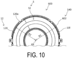
- FIG. 10 is a cross-sectional view of the fixed body 10 in a plane orthogonal to the rotation axis AX for illustrating the inhibiting portion 600.
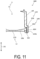
- FIG. 11 is a cross-sectional view of the fixed body 10 in a plane parallel to the radial direction of the rotation axis AX and the first direction D1 for illustrating the inhibiting portion 600.
- the inhibiting portion 600 is configured by the outer-circumferential cylindrical portion 140 and the outer periphery 120a of the first ring portion 120 coming into contact with each other such that the outer-circumferential cylindrical portion 140 is outside the outer periphery 120a in the radial direction of the rotation axis AX.
- the inhibiting portion 600 is provided separately from the engagement portion 18.
- the outer-circumferential cylindrical portion 140 includes a large diameter portion 602 that is in contact with the outer periphery 120a of the first ring portion 120.
- a diameter R1 of the large diameter portion 602 is larger than the diameter of the outer-circumferential cylindrical portion 140 anywhere other than at the large diameter portion 602.
- the diameter R1 of the large diameter portion 602 is larger than a diameter R2 of the outer periphery 120a.
- the large diameter portion 602 need not be provided.
- the outer-circumferential cylindrical portion 140 covers the outer periphery 120a of the first ring portion 120 in the radial direction of the rotation axis AX.
- the second coupling portion 162 is exposed at the bottom portion 10b of the fixed body 10 and is not exposed at the side wall 10l of the fixed body 10.
- the first ring portion 120 includes an extending portion 606 that extends in the first direction D1.
- the outer periphery 120a of the first ring portion 120 is constituted by the outer periphery of the extending portion 606.
- a surface 604 of the large diameter portion 602 is in contact with the extending portion 606 that extends in the first direction D1.
- a pathway from the second coupling portion 162 to the first space S1 is long in the first direction D1.
- the surface 604 need not be in contact with the extending portion 606.
- the extending portion 606 may be omitted.
- the rotary connector device 100 and features of the rotary connector device 100 are summarized below.
- the rotary connector device 100 includes the fixed body 10, the rotation body 20, and the inhibiting structure 60.
- the fixed body 10 is configured by the first fixed body portion 12 and the second fixed body portion 14 disposed facing each other with the space S being defined between the first fixed body portion 12 and the second fixed body portion 14, and coupled at the coupling portion 16.
- the coupling portion 16 is exposed to the outer surface 10s of the fixed body 10.
- the inhibiting structure 60 inhibits foreign matter from entering the space S between the first fixed body portion 12 and the second fixed body portion 14. With this configuration, deterioration of the rotary connector device 100 due to the entry of foreign matter is inhibited. As a result, the environmental resistance of the rotary connector device 100 is improved.
- the foreign matter is, for example, fluid water and dust.
- the rotary connector device 100 further includes the connection conductor 50 disposed on the fixed body 10 in the second space S2 included in the space S.
- the connection conductor 50 is connected to a first end of the cable conductor wire 34, and the rotation body 20 is connected to a second end of the cable conductor wire 34.
- connection conductor 50 With this configuration, foreign matter is inhibited from adhering to the connection conductor 50, and the connection conductor 50 is prevented from degrading.
- the inhibiting structure 60 includes the protecting member 62 configured to increase the length of the gap passageway between the coupling portion 16 and the connection conductor 50. This configuration can inhibit foreign matter from reaching the connection conductor 50.
- the inhibiting structure 60 includes the protecting member 62 disposed between the coupling portion 16 and the connection conductor 50 in the second space S2 included in the space S. This configuration can inhibit foreign matter from reaching the connection conductor 50.
- the protecting member 62 is in contact with at least one of the inner surface 124i of the first fixed body portion 12 and the inner surface 146i of the second fixed body portion 14 at the coupling portion 16. With this configuration, entry of foreign matter is inhibited because the protecting member 62 is disposed to fill the coupling portion 16.
- the rotation body 20 is rotatable about the rotation axis AX in the first direction D1.
- the coupling portion 16 is provided on the outer periphery 10o of the fixed body 10 when viewed in the first direction D1.
- the protecting member 62 is disposed between the coupling portion 16 and the connection conductor 50 in the second direction D2 orthogonal to the first direction D1.
- the protecting member 62 extends from the first fixed body portion 12 in the first direction D1. This configuration inhibits foreign matter from flowing around the protecting member 62 because the gap passageway between the coupling portion 16 and the connection conductor 50 extends in the first direction D1.
- the fixed body 10 includes the engagement portion 18 configured to engage the first fixed body portion 12 and the second fixed body portion 14.
- the protecting member 62 is disposed between the engagement portion 18 and the connection conductor 50.
- the length L1 of the protecting member in the third direction D3 orthogonal to the first direction D1 and following the outer surface 10s of the fixed body 10 is longer than the length L2 of the engagement portion 18 in the third direction D3.
- This configuration can inhibit foreign matter from flowing around the protecting member 62 that is long in the third direction D3, even in a case where foreign matter enters at the coupling portion 16 in the vicinity of the engagement portion 18.
- the engagement portion 18 includes the engagement frame 180 attached to one of the first fixed body portion 12 and the second fixed body portion 14, and the engagement claw 188 attached to the other of the first fixed body portion 12 and the second fixed body portion 14. Even in a case where engagement between the engagement frame 180 and the engagement claw 188 loosens, the protecting member 62 is disposed corresponding to the engagement portion 18, and thus this configuration can effectively inhibit the entry of foreign matter.
- the protecting member 62 includes an insulating material. With this configuration, even in a case where the protecting member 62 is in contact with the connection conductor 50, electrical connection problems such as short-circuiting can be inhibited.
- the rotary connector device 100 includes the first connector 40 provided on the outside of the fixed body 10 and including the first terminal 400 electrically connected to the connection conductor 50. This configuration improves connectivity between the rotary connector device 100 and an external cable.
- the rotary connector device 100 includes the insulating supporting body 54 that supports the connection conductor 50 and is attached to the fixed body 10 in the space S. This configuration can inhibit electrical connection problems such as short-circuiting between the connection conductor 50 and another conductor.
- the space S includes the first space S1 and the second space S2.
- the rotation body 20 is disposed corresponding to the first space S1.
- the connection conductor 50 is disposed in the second space S2.
- the cable 30 includes the cable conductor wire 34 and the insulating covering member 36 covering the cable conductor wire 34.
- the cable 30 is disposed in a space (first space S1) between the rotation body 20 and the fixed body 10.
- the inhibiting structure 60 includes the inhibiting portion 600 configured by the second fixed body portion 14 covering the first fixed body portion 12 in the radial direction of the rotation axis AX.
- the surface 604 of the second fixed body portion 14 and the outer periphery 120a of the first ring portion 120 of the first fixed body portion 12 are in contact with each other.
- FIG. 9 is a cross-sectional view corresponding to the cross-sectional view illustrated in FIG. 7 .
- the rotary connector device according to the second embodiment differs from the rotary connector device 100 according to the first embodiment in terms of the structure defining the second space S2 and the configuration of a protecting member 70 (corresponds to the protecting member 62). Descriptions of identical configurations are omitted.
- the second space S2 is defined by the first wall 124, the second wall 144, a third wall 170, and a fourth wall 172.
- the third wall 170 extends upward from the first wall 124.
- the fourth wall 172 extends downward from the second wall 144.
- An upper end of the third wall 170 and a lower end of the fourth wall 172 are coupled at a first coupling portion 160a.
- the first coupling portion 160a is separated from the first wall 124 and the second wall 144 in the first direction D1.
- the protecting member 70 differs from the protecting member 62 in terms of position in the first direction D1. Further, unlike the protecting member 62, the protecting member 70 is provided separately from the first wall 124. As illustrated in FIG. 9 , the protecting member 70 is separated from the first wall 124 and the second wall 144 in the first direction D1 so as to face the first coupling portion 160a.
- a length L11 of the protecting member 70 in the first direction D1 includes a length L12 from a position facing the first coupling portion 160a in the second direction D2 to a lower end of the protecting member 70, and a length L13 from a position facing the first coupling portion 160a in the second direction D2 to an upper end of the protecting member 70.
- the length L12 is longer than the length L13.
- the gap passageway extending from the first coupling portion 160a to the plurality of connection conductors 50 around a lower portion of the protecting member 70 is longer than a gap passageway extending from the first coupling portion 160a to the plurality of connection conductors 50 around an upper portion of the protecting member 70. Therefore, this configuration effectively inhibits foreign matter from reaching the plurality of connection conductors 50, even in a case where foreign matter that has entered through the first coupling portion 160a easily moves downward.
- the length L11, the length L12, and the length L13 of the protecting member 70 are not limited to those illustrated in FIG. 9 .
Landscapes
- Connector Housings Or Holding Contact Members (AREA)
- Electric Cable Arrangement Between Relatively Moving Parts (AREA)
- Steering Controls (AREA)
- Details Of Connecting Devices For Male And Female Coupling (AREA)
Claims (13)
- Drehverbindervorrichtung, welche aufweist:einen fixierten Körper (10), der durch einen ersten fixierten Körperabschnitt (12) und einen zweiten fixierten Körperabschnitt (14) konfiguriert ist, die einander gegenüberliegend mit einem Raum (S) angeordnet sind, der zwischen dem ersten fixierten Körperabschnitt (12) und dem zweiten fixierten Körperabschnitt (14) definiert ist, und die an einem Kupplungsabschnitt (16) gekoppelt sind;einen Rotorkörper (20), der an dem fixierten Körper (10) drehbar angebracht ist; undeine Verhinderungsstruktur (60), die konfiguriert ist, um den Eintritt von Fremdmaterial durch den Kupplungsabschnitt (16) in den Raum (S) zu verhindern,wobei der Kupplungsabschnitt (16) zu einer Außenfläche des fixierten Körpers (10) freiliegt,wobei der Raum (S) einen ersten Raum (S1) zwischen dem Rotorkörper (20) und dem fixierten Körper (10) und einen zweiten Raum (S2) enthält,wobei ein Verbindungsleiter (50) an dem fixierten Körper (10) in dem zweiten Raum (S2) angeordnet ist, der definiert ist durch zumindest eine erste Wand (124), die sich in der radialen Richtung der Drehachse (AX) des ersten fixierten Körpers (12) auswärts erstreckt, eine zweite Wand (144), die sich in der radialen Richtung der Drehachse (AX) des zweiten fixierten Körperabschnitts (14) gegenüber der ersten Wand auswärts erstreckt, sowie eine dritte Wand (146), die mit der zweiten Wand (144) verbunden ist und sich parallel zur Drehachse (AX) zu der ersten Wand (124) hin erstreckt,wobei der Verbindungsleiter (50) mit einem ersten Ende eines Kabelleitungsdrahts (34) eines in den ersten Raum (S1) gewickelten Kabels (30, 32) verbunden ist, wobei der Rotorkörper (20) in dem ersten Raum (S1) angeordnet ist und mit einem zweiten Ende des Kabelleiterdrahts (34) verbunden ist,wobei die Verhinderungsstruktur (60) ein Schutzelement (62, 70) enthält, das eine Durchgangslücke zwischen dem Kupplungsabschnitt (16) und dem Verbindungsleiter (50) definiert, oderwobei das Schutzelement (62, 70) zwischen dem Kupplungsabschnitt (16) und dem Verbindungsleiter (50) in dem zweiten Raum (S2) angeordnet ist,dadurch gekennzeichnet, dass sich das Schutzelement (62, 70) in den zweiten Raum (S2) zwischen den radial gegenüberliegenden Oberflächen des Kabels (30, 32) und eines ersten Kupplungsabschnitts (160) des Kupplungsabschnitts (16), der zu einer Außenfläche (124o) ersten Wand (124) und einer Außenfläche (146o) der dritten Wand (146) freiliegt, durch eine Überlappung des ersten Kupplungsabschnitts (160), des Schutzelements (62, 70) und des Verbindungsleiters (50) erstreckt, wenn man den fixierten Körper (10) in der radialen Richtung des Rotorkörpers (10) von dem Kupplungsabschnitt (16) zu dem Kabel (30, 32) betrachtet.
- Die Drehverbindervorrichtung nach Anspruch 1, wobei
das Schutzelement (62, 70) mit einer Innenfläche des ersten fixierten Körperabschnitts (12) und/oder einer Innenfläche des zweiten fixierten Körperabschnitts (14) an dem Kupplungsabschnitt (16) in Kontakt steht. - Die Drehverbindervorrichtung nach Anspruch 1 oder 2, wobeider Rotorkörper (20) um eine Drehachse entlang einer ersten Richtung (D1) herum drehbar ist,der Kupplungsabschnitt (16), bei Betrachtung in der ersten Richtung (D1), an einem Außenumfang des fixierten Körpers (10) vorgesehen ist,das Schutzelement (62) zwischen dem Kupplungsabschnitt (16) und dem Verbindungsleiter (50) in einer zur ersten Richtung (D1) orthogonalen zweiten Richtung (D2) angeordnet ist, undsich das Schutzelement (62) von dem ersten fixierten Körperabschnitt (12) oder dem zweiten fixierten Körperabschnitt (14) in der ersten Richtung (D1) erstreckt.
- Die Drehverbindervorrichtung nach Anspruch 3, wobeider fixierte Körper (20) einen Eingriffsabschnitt (18) enthält, der konfiguriert ist, um den ersten fixierten Körperabschnitt (12) und den zweiten fixierten Körperabschnitt (14) miteinander in Eingriff zu bringen, unddas Schutzelement (62) in der zweiten Richtung (D2) zwischen dem Eingriffsabschnitt (18) und dem Verbindungsleiter (50) angeordnet ist.
- Die Drehverbindervorrichtung nach Anspruch 4, wobei
eine Länge des Schutzelements (62) in einer dritten Richtung (D3), die orthogonal zur ersten Richtung (D1) ist und der Außenoberfläche folgt, länger ist als eine Länge des Eingriffsabschnitts (18) in der dritten Richtung (D3). - Die Drehverbindervorrichtung nach Anspruch 4 oder 5, wobei der Eingriffsabschnitt (18) enthält:einen Eingriffsrahmen (180), der an einem des ersten fixierten Körperabschnitts (12) und des zweiten fixierten Körperabschnitts (14) angebracht ist; undeine Eingriffsklaue (188), die an dem anderen des ersten fixierten Körperabschnitts (12) und des zweiten fixierten Körperabschnitts (14) angebracht ist.
- Die Drehverbindervorrichtung nach einem der Ansprüche 1 bis 6, wobei das Schutzelement (62, 70) ein Isoliermaterial enthält.
- Die Drehverbindervorrichtung nach einem der Ansprüche 1 bis 7, die ferner umfasst:
einen ersten Verbinder (40), der außerhalb des fixierten Körpers (10) zur Verbindung mit einem externen Kabel angeordnet ist und einen Anschluss enthält, der mit dem Verbindungsleiter (50) elektrisch verbunden ist. - Die Drehverbindervorrichtung nach Anspruch 8, wobei der erste Verbinder (40) teilweise in dem zweiten Raum (S2) angeordnet ist.
- Die Drehverbindervorrichtung nach einem der Ansprüche 1 bis 9, die ferner umfasst:
einen isolatierenden Trägerkörper (54), der konfiguriert ist, um den Verbindungsleiter (50) zu tragen und an dem fixierten Körper (10) in dem zweiten Raum (S2) angebracht ist. - Die Drehverbindervorrichtung nach einem der Ansprüche 1 bis 10,
wobei das Kabel (30, 32) einen Kabelleitungsdraht (34) und ein den Kabelleitungsdraht (34) abdeckendes isolierendes Abdeckelement (36) enthält. - Die Drehverbindervorrichtung nach einem der Ansprüche 1 bis 11,
wobei die Verhinderungsstruktur (60) einen Verhinderungsabschnitt (600) enthält, der durch den zweiten fixierten Körperabschnitt (14) konfiguriert ist, der den ersten fixierten Körperabschnitt (12) in radialer Richtung der Drehachse des Rotorkörpers (20) abdeckt. - Die Drehverbindervorrichtung nach Anspruch 12, wobei eine Oberfläche des zweiten fixierten Körperabschnitts (14) in der radialen Richtung mit einem Außenumfang des ersten fixierten Körperabschnitts (12) in Kontakt steht.
Applications Claiming Priority (3)
| Application Number | Priority Date | Filing Date | Title |
|---|---|---|---|
| JP2018069552 | 2018-03-30 | ||
| JP2018106005 | 2018-06-01 | ||
| PCT/JP2019/011824 WO2019188700A1 (ja) | 2018-03-30 | 2019-03-20 | 回転コネクタ装置およびその固定体 |
Publications (3)
| Publication Number | Publication Date |
|---|---|
| EP3761459A1 EP3761459A1 (de) | 2021-01-06 |
| EP3761459A4 EP3761459A4 (de) | 2021-01-13 |
| EP3761459B1 true EP3761459B1 (de) | 2023-07-19 |
Family
ID=68060000
Family Applications (1)
| Application Number | Title | Priority Date | Filing Date |
|---|---|---|---|
| EP19776607.4A Active EP3761459B1 (de) | 2018-03-30 | 2019-03-20 | Rotationssteckverbinder |
Country Status (6)
| Country | Link |
|---|---|
| US (1) | US11196225B2 (de) |
| EP (1) | EP3761459B1 (de) |
| JP (1) | JP7296366B2 (de) |
| KR (1) | KR102432812B1 (de) |
| CN (1) | CN111903016B (de) |
| WO (1) | WO2019188700A1 (de) |
Families Citing this family (1)
| Publication number | Priority date | Publication date | Assignee | Title |
|---|---|---|---|---|
| WO2023008414A1 (ja) * | 2021-07-28 | 2023-02-02 | 古河電気工業株式会社 | 回転コネクタ装置および回転コネクタ装置の製造方法 |
Family Cites Families (19)
| Publication number | Priority date | Publication date | Assignee | Title |
|---|---|---|---|---|
| US6962497B2 (en) * | 2003-04-16 | 2005-11-08 | The Furukawa Electric Co., Ltd. | Rotary connector having an identifiable neutral position |
| JP2006120512A (ja) * | 2004-10-22 | 2006-05-11 | Alps Electric Co Ltd | 回転コネクタ |
| JP2007220505A (ja) * | 2006-02-17 | 2007-08-30 | Yazaki Corp | 回転コネクタ装置 |
| JP2011018618A (ja) | 2009-07-10 | 2011-01-27 | Alps Electric Co Ltd | 回転コネクタ |
| WO2011122469A1 (ja) | 2010-03-30 | 2011-10-06 | 古河電気工業株式会社 | 回転コネクタ装置 |
| JP5117529B2 (ja) * | 2010-03-30 | 2013-01-16 | 古河電気工業株式会社 | 回転コネクタ装置 |
| JP5634774B2 (ja) * | 2010-07-06 | 2014-12-03 | 矢崎総業株式会社 | 防水ケース |
| EP2685571B1 (de) | 2011-03-09 | 2017-05-03 | Furukawa Electric Co., Ltd. | Drehbare steckverbinderanordnung |
| CN102684024B (zh) * | 2011-03-15 | 2014-07-09 | 阿尔卑斯电气株式会社 | 旋转连接器 |
| JP5624972B2 (ja) * | 2011-10-31 | 2014-11-12 | 古河電気工業株式会社 | 回転コネクタ装置 |
| JP3175246U (ja) * | 2012-02-15 | 2012-04-26 | 秀彰 西田 | カバー付きコンセントタップ |
| JP5802156B2 (ja) * | 2012-03-14 | 2015-10-28 | アルプス電気株式会社 | 回転コネクタ |
| JP3183930U (ja) | 2013-03-26 | 2013-06-06 | アルプス電気株式会社 | リードブロックおよびリードブロックを備えた回転コネクタ |
| CN203674465U (zh) * | 2013-10-29 | 2014-06-25 | 四川泛华电器有限责任公司 | 一种密封车用控制或保护单元电源端的装置 |
| CN204333541U (zh) * | 2014-12-15 | 2015-05-13 | 余姚市耀鸿霓虹电子有限公司 | 一种触杆可收纳的插头 |
| JP6605337B2 (ja) * | 2016-01-13 | 2019-11-13 | アルプスアルパイン株式会社 | 回転コネクタ |
| JP6599241B2 (ja) * | 2016-01-13 | 2019-10-30 | アルプスアルパイン株式会社 | 回転コネクタ |
| WO2017170752A1 (ja) * | 2016-03-31 | 2017-10-05 | 古河電気工業株式会社 | 回転コネクタ装置 |
| JP6696840B2 (ja) | 2016-06-21 | 2020-05-20 | 古河電気工業株式会社 | 回転コネクタ装置 |
-
2019
- 2019-03-20 KR KR1020207027300A patent/KR102432812B1/ko active Active
- 2019-03-20 CN CN201980018459.5A patent/CN111903016B/zh active Active
- 2019-03-20 WO PCT/JP2019/011824 patent/WO2019188700A1/ja not_active Ceased
- 2019-03-20 EP EP19776607.4A patent/EP3761459B1/de active Active
- 2019-03-20 JP JP2020510800A patent/JP7296366B2/ja active Active
-
2020
- 2020-09-17 US US17/023,374 patent/US11196225B2/en active Active
Also Published As
| Publication number | Publication date |
|---|---|
| JPWO2019188700A1 (ja) | 2021-04-01 |
| CN111903016A (zh) | 2020-11-06 |
| WO2019188700A1 (ja) | 2019-10-03 |
| EP3761459A1 (de) | 2021-01-06 |
| KR20200131257A (ko) | 2020-11-23 |
| KR102432812B1 (ko) | 2022-08-16 |
| JP7296366B2 (ja) | 2023-06-22 |
| EP3761459A4 (de) | 2021-01-13 |
| US20210006022A1 (en) | 2021-01-07 |
| US11196225B2 (en) | 2021-12-07 |
| CN111903016B (zh) | 2022-01-11 |
Similar Documents
| Publication | Publication Date | Title |
|---|---|---|
| CN102255188B (zh) | 手柄式连接器 | |
| EP2744057B1 (de) | Wasserdichte struktur für einen kabelbaum | |
| EP2666673B1 (de) | Kabelbaum-Abschirmungsstruktur | |
| CN102859802A (zh) | 连接器 | |
| WO2011007607A1 (ja) | 防水構造 | |
| CN102099972B (zh) | 连接器连接部的防水构造 | |
| CN107431288B (zh) | Hv线缆套件 | |
| US10297364B2 (en) | Wire harness | |
| EP3761459B1 (de) | Rotationssteckverbinder | |
| JP5802010B2 (ja) | ワイヤハーネスのシールド構造 | |
| US11909149B2 (en) | Rotary connector device and rotation body of rotary connector device | |
| US20190123610A1 (en) | Motor assembly | |
| CN113241567A (zh) | 一种多通道镓合金液态金属导电滑环 | |
| EP3859910B1 (de) | Drehbare verbindervorrichtung | |
| EP3817159B1 (de) | Drehverbindervorrichtung und fixer körper der drehverbindervorrichtung | |
| JP6622034B2 (ja) | 電気接続箱、及び、ワイヤハーネス | |
| CN103548211B (zh) | 连接器 | |
| JP7221721B2 (ja) | 巻取装置 | |
| JP6807025B2 (ja) | コネクタ | |
| JP2024060598A (ja) | コネクタおよびコネクタアセンブリ | |
| JP2019068682A (ja) | 導線部材および駆動ユニット | |
| US9647440B2 (en) | Composite direct connector for high voltage line | |
| JP2015011946A (ja) | シールドコネクタ | |
| WO2020171121A1 (ja) | 回転コネクタ装置 |
Legal Events
| Date | Code | Title | Description |
|---|---|---|---|
| STAA | Information on the status of an ep patent application or granted ep patent |
Free format text: STATUS: THE INTERNATIONAL PUBLICATION HAS BEEN MADE |
|
| PUAI | Public reference made under article 153(3) epc to a published international application that has entered the european phase |
Free format text: ORIGINAL CODE: 0009012 |
|
| STAA | Information on the status of an ep patent application or granted ep patent |
Free format text: STATUS: REQUEST FOR EXAMINATION WAS MADE |
|
| REG | Reference to a national code |
Ref legal event code: R079 Ipc: H01R0013520000 Ref country code: DE Ref legal event code: R079 Ref document number: 602019033120 Country of ref document: DE Free format text: PREVIOUS MAIN CLASS: H01R0035040000 Ipc: H01R0013520000 |
|
| 17P | Request for examination filed |
Effective date: 20201002 |
|
| AK | Designated contracting states |
Kind code of ref document: A1 Designated state(s): AL AT BE BG CH CY CZ DE DK EE ES FI FR GB GR HR HU IE IS IT LI LT LU LV MC MK MT NL NO PL PT RO RS SE SI SK SM TR |
|
| AX | Request for extension of the european patent |
Extension state: BA ME |
|
| A4 | Supplementary search report drawn up and despatched |
Effective date: 20201216 |
|
| RIC1 | Information provided on ipc code assigned before grant |
Ipc: H01R 13/52 20060101AFI20201210BHEP Ipc: H01R 35/02 20060101ALI20201210BHEP |
|
| DAV | Request for validation of the european patent (deleted) | ||
| DAX | Request for extension of the european patent (deleted) | ||
| STAA | Information on the status of an ep patent application or granted ep patent |
Free format text: STATUS: EXAMINATION IS IN PROGRESS |
|
| 17Q | First examination report despatched |
Effective date: 20210923 |
|
| GRAP | Despatch of communication of intention to grant a patent |
Free format text: ORIGINAL CODE: EPIDOSNIGR1 |
|
| STAA | Information on the status of an ep patent application or granted ep patent |
Free format text: STATUS: GRANT OF PATENT IS INTENDED |
|
| INTG | Intention to grant announced |
Effective date: 20230215 |
|
| GRAS | Grant fee paid |
Free format text: ORIGINAL CODE: EPIDOSNIGR3 |
|
| GRAA | (expected) grant |
Free format text: ORIGINAL CODE: 0009210 |
|
| STAA | Information on the status of an ep patent application or granted ep patent |
Free format text: STATUS: THE PATENT HAS BEEN GRANTED |
|
| P01 | Opt-out of the competence of the unified patent court (upc) registered |
Effective date: 20230516 |
|
| AK | Designated contracting states |
Kind code of ref document: B1 Designated state(s): AL AT BE BG CH CY CZ DE DK EE ES FI FR GB GR HR HU IE IS IT LI LT LU LV MC MK MT NL NO PL PT RO RS SE SI SK SM TR |
|
| REG | Reference to a national code |
Ref country code: GB Ref legal event code: FG4D |
|
| REG | Reference to a national code |
Ref country code: CH Ref legal event code: EP |
|
| REG | Reference to a national code |
Ref country code: DE Ref legal event code: R096 Ref document number: 602019033120 Country of ref document: DE |
|
| REG | Reference to a national code |
Ref country code: IE Ref legal event code: FG4D |
|
| REG | Reference to a national code |
Ref country code: LT Ref legal event code: MG9D |
|
| REG | Reference to a national code |
Ref country code: NL Ref legal event code: MP Effective date: 20230719 |
|
| REG | Reference to a national code |
Ref country code: AT Ref legal event code: MK05 Ref document number: 1590424 Country of ref document: AT Kind code of ref document: T Effective date: 20230719 |
|
| PG25 | Lapsed in a contracting state [announced via postgrant information from national office to epo] |
Ref country code: NL Free format text: LAPSE BECAUSE OF FAILURE TO SUBMIT A TRANSLATION OF THE DESCRIPTION OR TO PAY THE FEE WITHIN THE PRESCRIBED TIME-LIMIT Effective date: 20230719 |
|
| PG25 | Lapsed in a contracting state [announced via postgrant information from national office to epo] |
Ref country code: GR Free format text: LAPSE BECAUSE OF FAILURE TO SUBMIT A TRANSLATION OF THE DESCRIPTION OR TO PAY THE FEE WITHIN THE PRESCRIBED TIME-LIMIT Effective date: 20231020 |
|
| PG25 | Lapsed in a contracting state [announced via postgrant information from national office to epo] |
Ref country code: IS Free format text: LAPSE BECAUSE OF FAILURE TO SUBMIT A TRANSLATION OF THE DESCRIPTION OR TO PAY THE FEE WITHIN THE PRESCRIBED TIME-LIMIT Effective date: 20231119 |
|
| PG25 | Lapsed in a contracting state [announced via postgrant information from national office to epo] |
Ref country code: SE Free format text: LAPSE BECAUSE OF FAILURE TO SUBMIT A TRANSLATION OF THE DESCRIPTION OR TO PAY THE FEE WITHIN THE PRESCRIBED TIME-LIMIT Effective date: 20230719 Ref country code: RS Free format text: LAPSE BECAUSE OF FAILURE TO SUBMIT A TRANSLATION OF THE DESCRIPTION OR TO PAY THE FEE WITHIN THE PRESCRIBED TIME-LIMIT Effective date: 20230719 Ref country code: PT Free format text: LAPSE BECAUSE OF FAILURE TO SUBMIT A TRANSLATION OF THE DESCRIPTION OR TO PAY THE FEE WITHIN THE PRESCRIBED TIME-LIMIT Effective date: 20231120 Ref country code: NO Free format text: LAPSE BECAUSE OF FAILURE TO SUBMIT A TRANSLATION OF THE DESCRIPTION OR TO PAY THE FEE WITHIN THE PRESCRIBED TIME-LIMIT Effective date: 20231019 Ref country code: LV Free format text: LAPSE BECAUSE OF FAILURE TO SUBMIT A TRANSLATION OF THE DESCRIPTION OR TO PAY THE FEE WITHIN THE PRESCRIBED TIME-LIMIT Effective date: 20230719 Ref country code: LT Free format text: LAPSE BECAUSE OF FAILURE TO SUBMIT A TRANSLATION OF THE DESCRIPTION OR TO PAY THE FEE WITHIN THE PRESCRIBED TIME-LIMIT Effective date: 20230719 Ref country code: IS Free format text: LAPSE BECAUSE OF FAILURE TO SUBMIT A TRANSLATION OF THE DESCRIPTION OR TO PAY THE FEE WITHIN THE PRESCRIBED TIME-LIMIT Effective date: 20231119 Ref country code: HR Free format text: LAPSE BECAUSE OF FAILURE TO SUBMIT A TRANSLATION OF THE DESCRIPTION OR TO PAY THE FEE WITHIN THE PRESCRIBED TIME-LIMIT Effective date: 20230719 Ref country code: GR Free format text: LAPSE BECAUSE OF FAILURE TO SUBMIT A TRANSLATION OF THE DESCRIPTION OR TO PAY THE FEE WITHIN THE PRESCRIBED TIME-LIMIT Effective date: 20231020 Ref country code: FI Free format text: LAPSE BECAUSE OF FAILURE TO SUBMIT A TRANSLATION OF THE DESCRIPTION OR TO PAY THE FEE WITHIN THE PRESCRIBED TIME-LIMIT Effective date: 20230719 Ref country code: AT Free format text: LAPSE BECAUSE OF FAILURE TO SUBMIT A TRANSLATION OF THE DESCRIPTION OR TO PAY THE FEE WITHIN THE PRESCRIBED TIME-LIMIT Effective date: 20230719 |
|
| PG25 | Lapsed in a contracting state [announced via postgrant information from national office to epo] |
Ref country code: PL Free format text: LAPSE BECAUSE OF FAILURE TO SUBMIT A TRANSLATION OF THE DESCRIPTION OR TO PAY THE FEE WITHIN THE PRESCRIBED TIME-LIMIT Effective date: 20230719 |
|
| REG | Reference to a national code |
Ref country code: DE Ref legal event code: R097 Ref document number: 602019033120 Country of ref document: DE |
|
| PG25 | Lapsed in a contracting state [announced via postgrant information from national office to epo] |
Ref country code: ES Free format text: LAPSE BECAUSE OF FAILURE TO SUBMIT A TRANSLATION OF THE DESCRIPTION OR TO PAY THE FEE WITHIN THE PRESCRIBED TIME-LIMIT Effective date: 20230719 |
|
| PG25 | Lapsed in a contracting state [announced via postgrant information from national office to epo] |
Ref country code: SM Free format text: LAPSE BECAUSE OF FAILURE TO SUBMIT A TRANSLATION OF THE DESCRIPTION OR TO PAY THE FEE WITHIN THE PRESCRIBED TIME-LIMIT Effective date: 20230719 Ref country code: RO Free format text: LAPSE BECAUSE OF FAILURE TO SUBMIT A TRANSLATION OF THE DESCRIPTION OR TO PAY THE FEE WITHIN THE PRESCRIBED TIME-LIMIT Effective date: 20230719 Ref country code: ES Free format text: LAPSE BECAUSE OF FAILURE TO SUBMIT A TRANSLATION OF THE DESCRIPTION OR TO PAY THE FEE WITHIN THE PRESCRIBED TIME-LIMIT Effective date: 20230719 Ref country code: EE Free format text: LAPSE BECAUSE OF FAILURE TO SUBMIT A TRANSLATION OF THE DESCRIPTION OR TO PAY THE FEE WITHIN THE PRESCRIBED TIME-LIMIT Effective date: 20230719 Ref country code: DK Free format text: LAPSE BECAUSE OF FAILURE TO SUBMIT A TRANSLATION OF THE DESCRIPTION OR TO PAY THE FEE WITHIN THE PRESCRIBED TIME-LIMIT Effective date: 20230719 Ref country code: CZ Free format text: LAPSE BECAUSE OF FAILURE TO SUBMIT A TRANSLATION OF THE DESCRIPTION OR TO PAY THE FEE WITHIN THE PRESCRIBED TIME-LIMIT Effective date: 20230719 Ref country code: SK Free format text: LAPSE BECAUSE OF FAILURE TO SUBMIT A TRANSLATION OF THE DESCRIPTION OR TO PAY THE FEE WITHIN THE PRESCRIBED TIME-LIMIT Effective date: 20230719 |
|
| PLBE | No opposition filed within time limit |
Free format text: ORIGINAL CODE: 0009261 |
|
| STAA | Information on the status of an ep patent application or granted ep patent |
Free format text: STATUS: NO OPPOSITION FILED WITHIN TIME LIMIT |
|
| PG25 | Lapsed in a contracting state [announced via postgrant information from national office to epo] |
Ref country code: IT Free format text: LAPSE BECAUSE OF FAILURE TO SUBMIT A TRANSLATION OF THE DESCRIPTION OR TO PAY THE FEE WITHIN THE PRESCRIBED TIME-LIMIT Effective date: 20230719 |
|
| 26N | No opposition filed |
Effective date: 20240422 |
|
| PG25 | Lapsed in a contracting state [announced via postgrant information from national office to epo] |
Ref country code: SI Free format text: LAPSE BECAUSE OF FAILURE TO SUBMIT A TRANSLATION OF THE DESCRIPTION OR TO PAY THE FEE WITHIN THE PRESCRIBED TIME-LIMIT Effective date: 20230719 |
|
| REG | Reference to a national code |
Ref country code: CH Ref legal event code: PL |
|
| PG25 | Lapsed in a contracting state [announced via postgrant information from national office to epo] |
Ref country code: BG Free format text: LAPSE BECAUSE OF FAILURE TO SUBMIT A TRANSLATION OF THE DESCRIPTION OR TO PAY THE FEE WITHIN THE PRESCRIBED TIME-LIMIT Effective date: 20230719 |
|
| PG25 | Lapsed in a contracting state [announced via postgrant information from national office to epo] |
Ref country code: LU Free format text: LAPSE BECAUSE OF NON-PAYMENT OF DUE FEES Effective date: 20240320 |
|
| PG25 | Lapsed in a contracting state [announced via postgrant information from national office to epo] |
Ref country code: MC Free format text: LAPSE BECAUSE OF FAILURE TO SUBMIT A TRANSLATION OF THE DESCRIPTION OR TO PAY THE FEE WITHIN THE PRESCRIBED TIME-LIMIT Effective date: 20230719 |
|
| GBPC | Gb: european patent ceased through non-payment of renewal fee |
Effective date: 20240320 |
|
| PG25 | Lapsed in a contracting state [announced via postgrant information from national office to epo] |
Ref country code: MC Free format text: LAPSE BECAUSE OF FAILURE TO SUBMIT A TRANSLATION OF THE DESCRIPTION OR TO PAY THE FEE WITHIN THE PRESCRIBED TIME-LIMIT Effective date: 20230719 Ref country code: LU Free format text: LAPSE BECAUSE OF NON-PAYMENT OF DUE FEES Effective date: 20240320 Ref country code: BG Free format text: LAPSE BECAUSE OF FAILURE TO SUBMIT A TRANSLATION OF THE DESCRIPTION OR TO PAY THE FEE WITHIN THE PRESCRIBED TIME-LIMIT Effective date: 20230719 |
|
| REG | Reference to a national code |
Ref country code: BE Ref legal event code: MM Effective date: 20240331 |
|
| PG25 | Lapsed in a contracting state [announced via postgrant information from national office to epo] |
Ref country code: BE Free format text: LAPSE BECAUSE OF NON-PAYMENT OF DUE FEES Effective date: 20240331 |
|
| PG25 | Lapsed in a contracting state [announced via postgrant information from national office to epo] |
Ref country code: GB Free format text: LAPSE BECAUSE OF NON-PAYMENT OF DUE FEES Effective date: 20240320 |
|
| PG25 | Lapsed in a contracting state [announced via postgrant information from national office to epo] |
Ref country code: FR Free format text: LAPSE BECAUSE OF NON-PAYMENT OF DUE FEES Effective date: 20240331 |
|
| PG25 | Lapsed in a contracting state [announced via postgrant information from national office to epo] |
Ref country code: IE Free format text: LAPSE BECAUSE OF NON-PAYMENT OF DUE FEES Effective date: 20240320 |
|
| PG25 | Lapsed in a contracting state [announced via postgrant information from national office to epo] |
Ref country code: IE Free format text: LAPSE BECAUSE OF NON-PAYMENT OF DUE FEES Effective date: 20240320 Ref country code: GB Free format text: LAPSE BECAUSE OF NON-PAYMENT OF DUE FEES Effective date: 20240320 Ref country code: FR Free format text: LAPSE BECAUSE OF NON-PAYMENT OF DUE FEES Effective date: 20240331 Ref country code: BE Free format text: LAPSE BECAUSE OF NON-PAYMENT OF DUE FEES Effective date: 20240331 Ref country code: CH Free format text: LAPSE BECAUSE OF NON-PAYMENT OF DUE FEES Effective date: 20240331 |
|
| PG25 | Lapsed in a contracting state [announced via postgrant information from national office to epo] |
Ref country code: CY Free format text: LAPSE BECAUSE OF FAILURE TO SUBMIT A TRANSLATION OF THE DESCRIPTION OR TO PAY THE FEE WITHIN THE PRESCRIBED TIME-LIMIT; INVALID AB INITIO Effective date: 20190320 |
|
| PG25 | Lapsed in a contracting state [announced via postgrant information from national office to epo] |
Ref country code: HU Free format text: LAPSE BECAUSE OF FAILURE TO SUBMIT A TRANSLATION OF THE DESCRIPTION OR TO PAY THE FEE WITHIN THE PRESCRIBED TIME-LIMIT; INVALID AB INITIO Effective date: 20190320 |
|
| PG25 | Lapsed in a contracting state [announced via postgrant information from national office to epo] |
Ref country code: TR Free format text: LAPSE BECAUSE OF FAILURE TO SUBMIT A TRANSLATION OF THE DESCRIPTION OR TO PAY THE FEE WITHIN THE PRESCRIBED TIME-LIMIT Effective date: 20230719 |
|
| PGFP | Annual fee paid to national office [announced via postgrant information from national office to epo] |
Ref country code: DE Payment date: 20260128 Year of fee payment: 8 |