EP2685571B1 - Drehbare steckverbinderanordnung - Google Patents
Drehbare steckverbinderanordnung Download PDFInfo
- Publication number
- EP2685571B1 EP2685571B1 EP12755404.6A EP12755404A EP2685571B1 EP 2685571 B1 EP2685571 B1 EP 2685571B1 EP 12755404 A EP12755404 A EP 12755404A EP 2685571 B1 EP2685571 B1 EP 2685571B1
- Authority
- EP
- European Patent Office
- Prior art keywords
- diametrical direction
- restriction section
- direction restriction
- cable
- rotator
- Prior art date
- Legal status (The legal status is an assumption and is not a legal conclusion. Google has not performed a legal analysis and makes no representation as to the accuracy of the status listed.)
- Not-in-force
Links
- 230000004308 accommodation Effects 0.000 claims description 37
- 238000004804 winding Methods 0.000 claims description 4
- 208000027418 Wounds and injury Diseases 0.000 description 83
- 206010070245 Foreign body Diseases 0.000 description 17
- 239000004576 sand Substances 0.000 description 16
- 239000004020 conductor Substances 0.000 description 5
- 230000037431 insertion Effects 0.000 description 4
- 238000003780 insertion Methods 0.000 description 4
- 230000005540 biological transmission Effects 0.000 description 2
- 238000005452 bending Methods 0.000 description 1
- 230000001419 dependent effect Effects 0.000 description 1
- 230000000694 effects Effects 0.000 description 1
Images


Classifications
-
- H—ELECTRICITY
- H01—ELECTRIC ELEMENTS
- H01R—ELECTRICALLY-CONDUCTIVE CONNECTIONS; STRUCTURAL ASSOCIATIONS OF A PLURALITY OF MUTUALLY-INSULATED ELECTRICAL CONNECTING ELEMENTS; COUPLING DEVICES; CURRENT COLLECTORS
- H01R13/00—Details of coupling devices of the kinds covered by groups H01R12/70 or H01R24/00 - H01R33/00
- H01R13/46—Bases; Cases
- H01R13/52—Dustproof, splashproof, drip-proof, waterproof, or flameproof cases
-
- B—PERFORMING OPERATIONS; TRANSPORTING
- B60—VEHICLES IN GENERAL
- B60R—VEHICLES, VEHICLE FITTINGS, OR VEHICLE PARTS, NOT OTHERWISE PROVIDED FOR
- B60R16/00—Electric or fluid circuits specially adapted for vehicles and not otherwise provided for; Arrangement of elements of electric or fluid circuits specially adapted for vehicles and not otherwise provided for
- B60R16/02—Electric or fluid circuits specially adapted for vehicles and not otherwise provided for; Arrangement of elements of electric or fluid circuits specially adapted for vehicles and not otherwise provided for electric constitutive elements
- B60R16/023—Electric or fluid circuits specially adapted for vehicles and not otherwise provided for; Arrangement of elements of electric or fluid circuits specially adapted for vehicles and not otherwise provided for electric constitutive elements for transmission of signals between vehicle parts or subsystems
- B60R16/027—Electric or fluid circuits specially adapted for vehicles and not otherwise provided for; Arrangement of elements of electric or fluid circuits specially adapted for vehicles and not otherwise provided for electric constitutive elements for transmission of signals between vehicle parts or subsystems between relatively movable parts of the vehicle, e.g. between steering wheel and column
-
- H—ELECTRICITY
- H01—ELECTRIC ELEMENTS
- H01R—ELECTRICALLY-CONDUCTIVE CONNECTIONS; STRUCTURAL ASSOCIATIONS OF A PLURALITY OF MUTUALLY-INSULATED ELECTRICAL CONNECTING ELEMENTS; COUPLING DEVICES; CURRENT COLLECTORS
- H01R35/00—Flexible or turnable line connectors, i.e. the rotation angle being limited
- H01R35/02—Flexible line connectors without frictional contact members
- H01R35/025—Flexible line connectors without frictional contact members having a flexible conductor wound around a rotation axis
Definitions
- the present invention relates to a rotatable connector device for, for example, electrically connecting elements on the side of a steering wheel of an automobile and the side of a vehicle body to each other.
- a rotatable connector device which is mountable on a vehicle such as an automobile or the like includes a stator which is to be fixed mainly on the side of a vehicle body and a rotator which is to be assembled to the side of a steering wheel.
- the stator and the rotator are assembled together coaxially so as to be rotatable with respect to each other.
- a flat cable is accommodated in an accommodation space formed by the stator and the rotator.
- the flat cable electrically connects an electric device such as a horn module, an airbag module, an audio control module or the like equipped on the side of the steering wheel and a power supply on the side of the vehicle body to each other.
- an electric device such as a horn module, an airbag module, an audio control module or the like equipped on the side of the steering wheel and a power supply on the side of the vehicle body to each other.
- Such a rotatable connector device which is proposed in, for example, JP 2003-197339 A includes a retainer provided on a bottom surface of an accommodation space and guides the flat cable to be wound around a rotation axis of the steering wheel.
- a retainer 40 is provided with a plurality of rotatable rollers 45 and a press guide 46 provided to stand in the vicinity of the rotatable roller 45. It is described that the retainer 40 rotates to assist a flat cable C to be wound and rewound in an accommodation space S and thus the rotatable connector device can follow a steering operation to smoothly rotate.
- the flat cable C includes an outside wound part Co wound along an inner circumferential surface of an outer casing 32 of a stator 30, a reversed part Cr wound along one of the rotatable rollers 45 rotatably supported by the retainer 40 to turn around in a U shape, and an inside wound part Ci wound along an outer circumferential surface of an inner circumferential cylindrical section 22 of a rotator 20.
- the rotatable connector device having such a structure operates as follows.
- the rotator 20 rotates clockwise (in the direction of X in FIG. 7 )
- the reversed part Cr of the flat cable C is pressed onto the press guide 46, and the retainer 40 can rotate clockwise by the pressing force.
- EP 2 078 640 A2 discloses a rotary connector with a stator having an outer cylindrical part, a rotor having an inner cylindrical part, and three or more flat cables that are arranged in an annular space between the outer and the inner cylindrical parts.
- a holder is rotatably disposed in the annular space and includes three or more openings through which reversed portions of the flat cables individually pass. The width of one of the openings in a circumferential direction is smaller than the respective widths of each of the other openings in the circumferential direction.
- the holder is driven by a pushing force from the flat cable that passes through the narrow opening. The bending strength of this flat cable is higher than that of each of the other flat cables.
- JP H09-45446 A discloses a steering roll connector with a flexible flat cable and dummy cables that are arranged on both sides of the flexible flat cable. Cylindrical rotary members of the steering roll connector are pushed by respective reverse parts of the dummy cables.
- the present invention has an object of providing a rotatable connector device which can maintain electrical connection between the rotator and the stator with certainty even when being contaminated with a foreign object such as sand or the like.
- the present invention is defined by the independent claim 1.
- the dependent claims concern optional features of some embodiments of the present invention.
- the present invention is directed to a rotatable connector device including a rotator including an annular rotatable-side ring plate and an inner circumferential cylindrical section having a cylindrical shape and formed along an inner circumferential edge of the rotatable-side ring plate; and a stator including an annular fixed-side ring plate and an outer circumferential cylindrical section having a cylindrical shape and formed along an outer circumferential edge of the fixed-side ring plate.
- stator and the rotator are in engagement with each other coaxially so as to be rotatable with respect to each other in a clockwise direction and a counterclockwise direction; and the rotatable-side ring plate and the inner circumferential cylindrical section of the rotator and the fixed-side ring plate and the outer circumferential cylindrical section of the stator form an accommodation space.
- the rotatable connector device further includes an annular retainer, for supporting a plurality of rotatable rollers, placed in a bottom part of the accommodation space; at least one flat cable for electrically connecting the side of the rotator and the side of the stator to each other and including a reversed part at which a winding direction of the flat cable is reversed, the flat cable being accommodated on the retainer in the accommodation space such that the flat cable can be wound and rewound; a flexible and elastic dummy cable having one end in a longitudinal direction thereof connected and fixed to the side of the rotator and the other end thereof connected and fixed to the side of the stator and including a reversed part directly wound along one of the rotatable rollers to reverse a winding direction thereof, the dummy cable being accommodated such that the dummy cable can be wound and rewound and being stacked on the flat cable; and a press guide, for allowing the reversed part of the dummy cable to be directly pressed thereon, provided on the retainer
- the dummy cable may have an approximately equivalent width to that of the flat cable.
- the dummy cable may be a band-like element which does not connect the retainer and the rotator to each other electrically, or may be a flat cable which has a conductor but does not connect the rotator and the stator to each other electrically.
- the dummy cable may be formed of only an insulating member having an insulating property without including a conductor.
- a rotatable connector device which can maintain electrical connection between the rotator and the stator with certainty even when being contaminated with a foreign object such as sand or the like can be provided.
- the dummy cable non-electrically connects the side of the rotator and the side of the stator to each other.
- the rotator rotates clockwise
- the reversed part of the dummy cable is pressed onto the press guide, and the retainer can rotate clockwise by the pressing force.
- the rotator and the stator can maintain the electrical connection to each other by the flat cable, with certainty.
- the reversed part of the dummy cable pressed onto the press guide can be prevented from being buckled or folded.
- a repulsive power is generated by the elasticity of the dummy cable in a diametrical direction of the rotator and the stator. This will be described in more detail.
- a repulsive power is generated outward in the diametrical direction.
- a repulsive power is generated inward in the diametrical direction.
- the dummy cable is wound and rewound while being pressed onto the side of the rotator and the side of the stator in the diametrical direction. Therefore, the dummy cable can be suppressed from, for example, being slack, and can contact the press guide with certainty.
- the retainer can be rotated by the dummy cable with certainty owing to the elasticity of the dummy cable, and also can follow the rotation of the rotator to rotate more smoothly. Since the retainer is smoothly rotated by the dummy cable, the flat cable can be wound and rewound without receiving excessive load and thus can be prevented from, for example, being broken.
- the retainer is rotated by the dummy cable which non-electrically connects the rotator and the stator to each other, so that the electrical connection between the rotator and the stator can be maintained with certainty even when the rotatable connector device is contaminated with a foreign object such as sand or the like.
- the reversed part of the flat cable may be located at a substantially central position in a circumferential direction between the rotatable rollers.
- Restriction sections for restricting a movement of the dummy cable or the flat cable in a diametric direction may be provided to stand on the retainer in the vicinity of the rotatable rollers, the restriction sections being provided at an interval which is larger than a moving range by which the reversed part of the flat cable moves in the circumferential direction until the retainer starts rotating after the rotator starts rotating.
- the reversed part of the flat cable when the rotator is still, the reversed part of the flat cable can be located with a sufficient distance from the restriction sections on the retainer. For this reason, even when the rotator rotates, the reversed part of the flat cable can be prevented from contacting the restriction sections on the retainer.
- the reversed part of the flat cable is not wound or rewound while being slid against the restriction sections on the retainer. Therefore, the flat cable can be prevented from being abraded or damaged.
- the reversed part of the flat cable is located with a sufficient distance from the restriction sections on the retainer, so that the flat cable is not abraded or damaged even when the rotator rotates while the rotatable connector device is contaminated with a foreign object such as sand or the like. Therefore, the electrical connection between the rotator and the stator can be maintained with more certainty.
- the dummy cable may have a length in the longitudinal direction which is shorter than that of the flat cable in the longitudinal direction.
- the dummy cable can be wound along the rotator while being stacked on the flat cable.
- the flat cable can be suppressed from, for example, being slack at the time of being wound or rewound, owing to the repulsive power of the reversed part of the dummy cable.
- the flat cable can be prevented from being abraded or damaged as a result of contacting the retainer or the like.
- the length of the dummy cable in the longitudinal direction is shorter than that of the flat cable in the longitudinal direction, so that the flat cable can be prevented from being contacting the restriction sections on the retainer or the like with more certainty. Therefore, the electrical connection between the rotator and the stator can be maintained with more certainty even when the rotatable connector device is contaminated with a foreign object such as sand or the like.
- a rotatable connector device which can maintain electrical connection between the rotator and the stator with certainty even when being contaminated with a foreign object such as sand or the like can be provided.
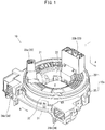
- FIG. 1 is an external isometric view of a steering roll connector 10.
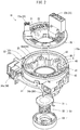
- FIG. 2 is an exploded isometric view of the steering roll connector 10.
- FIG. 3 is a plan view showing the steering roll connector 10 in this embodiment in the state where a rotator 20 is detached.
- FIG. 4 is a cross-sectional view taken along line A-A in FIG. 1 .
- the steering roll connector 10 in this embodiment includes a cable housing 10a, a retainer 40, and a rotation lock body 50.
- the cable housing 10a has a generally cylindrical shape having an insertion hole H at a central portion thereof as seen in a plan view.
- the insertion hole H runs through the cable housing 10a in a steering rotation axial direction (up-down direction in FIG. 4 ).
- the insertion hole H has a diameter which allows a steering shaft (not shown) protruding from a steering column (not shown) to be inserted into the insertion hole H.
- the cable housing 10a includes the stator 30 and the rotator 20 which are rotatable with respect to each other.
- a steering wheel (not shown) for performing a rotation operation is fixed to a top end of the steering shaft.
- the rotation lock body 50 includes a lock body 51, a spring bearing sleeve 53, and a return spring 52 provided between the lock body 51 and the spring bearing sleeve 53.
- the spring bearing sleeve 53 is pushed up against an urging force of the return spring 52, so that the rotator 20 can be locked by the lock body 51 so as not to rotate with respect to the stator 30.
- a boss (not shown) of a cored bar of the steering wheel is inserted, so that the rotator 20 can be released from the locked state by the lock body 51 to be permitted to freely rotate with respect to the stator 30.
- the rotator 20 includes a rotatable-side ring plate 21 having an annular shape and acting as a top board, and an inner circumferential cylindrical section 22 having a cylindrical shape and extending downward from an inner circumferential edge of the rotatable-side ring plate 21.
- the rotator 20 is fixed to the steering wheel and is rotatable integrally with the steering wheel.
- the rotator 20 is coaxially rotatable with a rotation axis of the steering wheel.
- the rotator 20 is provided with rotator-side connectors 23 integrally rotatable with the rotator 20.
- the rotator-side connectors 23 include a first rotator-side connector 23a and a second rotator-side connector 23b.
- the first rotator-side connector 23a and the second rotator-side connector 23b are located with a predetermined distance being kept therebetween in a circumferential direction of the rotatable-side ring plate 21, and each have a connector-connecting opening directed upward.
- the rotator-side connectors 23 are each connected to, for example, a cable (not shown) drawn from an electrical circuit of a horn switch, an airbag unit or the like located on the steering wheel.
- the stator 30 is fixed to an appropriate component on the side of the vehicle body, for example, a combination bracket switch (not shown) located inside the steering column, and is rotatable with respect to the steering wheel.
- the stator 30 includes a fixed-side ring plate 31 having an annular shape and acting as a bottom board and an outer circumferential cylindrical section 32 having a cylindrical shape and extending upward from an outer circumferential edge of the fixed-side ring plate 31.
- the outer circumferential edge of the fixed-side ring plate 31 and a bottom end of the outer circumferential cylindrical section 32 are engaged with each other to be integral.
- the outer circumferential cylindrical section 32 includes an outer-side outer circumferential cylindrical section 32o having a cylindrical shape and an inner-side outer circumferential cylindrical section 32i having a cylindrical shape and having a diameter slightly smaller than that of the outer-side outer circumferential cylindrical section 32o.
- the outer-side outer circumferential cylindrical section 32o and the inner-side outer circumferential cylindrical section 32i are located concentrically, and face and are close to each other in a radial direction.
- the outer circumferential cylindrical section 32 has a two-layer structure in a diametrical direction.
- a brim-shaped guide projection piece 33 is provided on the inner-side outer circumferential cylindrical section 32i.
- the guide projection piece 33 projects inward (internally) in the radial direction to guide a flat cable C and a dummy cable D described later from above.
- the stator 30 is provided with stator-side connectors 34.
- the stator-side connectors 34 include a first stator-side connector 34a and a second stator-side connector 34b.
- the first stator-side connector 34a and the second stator-side connector 34b are located outer to the outer circumferential cylindrical section 32 (outer-side outer circumferential cylindrical section 32o) while having a predetermined distance therebetween, and each have a connector-connecting opening directed in the same direction.
- stator-side connectors 34 are each connected to a cable (not shown) drawn from an electrical circuit or the like on the side of the vehicle body in a lower column cover (not shown).
- the fixed-side ring plate 31 of the stator 30 faces the rotatable-side ring plate 21 of the rotator 20 in the rotation axial direction
- the outer circumferential cylindrical section 32 of the stator 30 faces, and is located outer in the radial direction to, the inner circumferential cylindrical section 22 of the rotator 20.
- the accommodation space S accommodates the retainer 40, the flat cable C and the dummy cable D.
- the retainer 40 includes a plurality of rotatable rollers 45 and a base ring 41, and is placed on a bottom surface of the stator 30, which is an element to form the accommodating space S, such that the retainer 40 is rotatable around a rotation axis of the rotator 20.
- the base ring 41 includes a plate-like base ring main body 42 having an annular shape as seen in a plan view, roller supporting projections 43, diametrical direction restriction sections 44, and a press guide 46.
- the base ring main body 42 is slidable in the rotation direction with respect to the fixed-side ring plate 31, and is rotatable with respect to the stator 30.
- the roller supporting projections 43 are located at an equal interval in a circumferential direction of the base ring main body 42 and project upward so as to support the rotatable rollers 45.
- the diametrical direction restriction sections 44 are located between the roller supporting projections 43 adjacent to each other in the circumferential direction.
- the diametrical direction restriction sections 44 include a first diametrical direction restriction section 44a, a second diametrical direction restriction section 44b, a third diametrical direction restriction section 44c, and a fourth diametrical direction restriction section 44d, which have different shapes from each other in accordance with the path of the flat cable C and the dummy cable D.
- the diametrical direction restriction sections 44 are provided to stand upward from the base ring main body 42.
- the first diametrical direction restriction section 44a is provided to stand close to a convex side of a part of the dummy cable D which is wound in a U shape along one of the rotatable rollers 45, supported by the plurality of roller supporting projections 43, to turn around (convex side of a reversed part Dr of the dummy cable D described later.
- the first diametrical direction restriction section 44a has a concave shape, as seen in a plan view, having an opening on the diametrically outer side, so as to guide, from the diametrically outer side, the flat cable C (inside wound part Ci of the flat cable described later) and the dummy cable D (inside wound part Di of the dummy cable described later) which are wound along an outer circumferential surface of the inner circumferential cylindrical section 22 of the rotator 20 as seen in a plan view.
- the press guide 46 is formed integrally therewith.
- the press guide 46 is formed to be curved in a generally bow shape as seen in a plan view so as to be along the reversed part Dr of the dummy cable D.
- the second diametrical direction restriction section 44b is provided to stand close to the roller supporting projection 43 which is adjacent in the circumferential direction to the roller supporting projection 43 along which the reversed part Dr of the dummy cable D is wound, with the first diametrical direction restriction section 44a being interposed between these two roller supporting projections 43.
- the second diametrical direction restriction section 44b faces the first diametrical direction restriction section 44a in the circumferential direction, with the roller supporting projection 43 close to the second diametrical direction restriction section 44b being interposed between the second diametrical direction restriction section 44b and the first diametrical direction restriction section 44a.
- the second diametrical direction restriction section 44b has a generally concave shape, as seen in a plan view, having an opening on the side of the roller supporting projection 43 close thereto as seen in a plan view.
- the second diametrical direction restriction section 44b guides, from the diametrically outer side, the inside wound part Ci of the flat cable C and the inside wound part Di of the dummy cable D.
- the third diametrical direction restriction section 44c is provided to stand between the second diametrical direction restriction section 44b and the roller supporting projection 43 which is adjacent to the roller supporting projection 43 close to the second diametrical direction restriction section 44b. More specifically, the above adjacent roller supporting projection 43 is adjacent in the circumferential direction directed from the roller supporting projection 43 close to the second diametrical direction restriction section 44b toward the second diametrical direction restriction section 44b. The third diametrical direction restriction section 44c is close to the above adjacent roller supporting projection 43.
- the third diametrical direction restriction section 44c has a generally concave shape, as seen in a plan view, having an opening on the side of the roller supporting projection 43 close thereto as seen in a plan view.
- the third diametrical direction restriction section 44c guides, from the diametrically outer side, the inside wound part Ci of the flat cable C and the inside wound part Di of the dummy cable D.
- the fourth diametrical direction restriction section 44d is provided to stand in areas, between the roller supporting projections 43 adjacent to each other in a circumferential direction of the retainer 40, where none of the first diametrical direction restriction section 44a, the second diametrical direction restriction section 44b and the third diametrical direction restriction section 44c is provided to stand.
- the fourth diametrical direction restriction section 44d has a generally concave shape, as seen in a plan view, having an opening on the diametrically outer side so as to guide, from the diametrically outer side, the inside wound part Ci of the flat cable C and the inside wound part Di of the dummy cable D which are wound along the outer circumferential surface of the inner circumferential cylindrical section 22 of the rotator 20 as seen in a plan view.
- the rotatable rollers 45 are supported by the roller supporting projections 43 and are each rotatable around an axis thereof parallel to the rotation axis of the rotator 20.
- the flat cable C is a flexible band-like transmission line including a plurality of flat conductors which are located parallel to each other at a predetermined pitch and are covered with an insulating cover.
- the flat cable C is accommodated in the accommodation space S in a wound state, and electrically connects the first rotator-side connector 23a and the first stator-side connector 34a to each other.
- one end in a length direction of the flat cable C is connected to the first rotator-side connector 23a, and the other end thereof is connected to the first stator-side connector 34a.
- the flat cable C is supported by the retainer 40, which is located on the fixed-side ring plate 31 so as to be rotatable with respect thereto, in the accommodation space S inside the cable housing 10a. In the accommodation space S, the flat cable C is wound.
- the flat cable C is drawn from the first stator-side connector 34a into the accommodation space S. As shown in FIG. 3 and FIG. 4 , the flat cable C includes an outside wound part Co wound along an inner circumferential surface of the outer circumferential cylindrical section 32 (inner-side outer circumferential cylindrical section 32i) of the stator 30, outside the retainer 40.
- the flat cable C includes the reversed part Cr in the middle of the length direction thereof.
- the reversed part Cr is wound in a U shape along one of the rotatable rollers 45, close to the second diametrical direction restriction section 44b, to turn around.
- the reversed part Cr is located at a substantially central position in the circumferential direction between the second diametrical direction restriction section 44b and the third diametrical direction restriction section 44c so as to have a sufficient distance from each of the second diametrical direction restriction section 44b and the third diametrical direction restriction section 44c.
- the flat cable C also includes the inside wound part Ci, which is a part closer than the revered part Cr to a tip thereof in the length direction, and is wound along the outer circumferential surface of the inner circumferential cylindrical section 22 of the rotator 20, inside the retainer 40.
- the flat cable C is finally drawn out of the accommodation space S and is connected to the first rotator-side connector 23a.
- the dummy cable D is an elastic and flexible band-like cable covered with an insulating cover, and is shorter than the flat cable C in the length direction thereof.
- the dummy cable D is accommodated in the accommodation space S while being stacked on the flat cable C and wound, and non-electrically connects the rotator 20 and the stator 30 to each other.
- one end in the length direction of the dummy cable D is connected and thus fixed to a position in the vicinity of the first rotator-side connector 23a, and the other end thereof is connected and thus fixed to a position in the vicinity of the first stator-side connector 34a.
- the dummy cable D is drawn from the first stator-side connector 34a into the accommodation space S while being stacked on the flat cable C. As shown in FIG. 3 and FIG. 4 , the dummy cable D includes the outside wound part Do wound along the inner circumferential surface of the outer circumferential cylindrical section 32 (inner-side outer circumferential cylindrical section 32i) of the stator 30, outside the retainer 40.
- the dummy cable D includes the reversed part Dr in the middle of the length direction thereof.
- the reversed part Dr is wound in a U shape along the rotatable roller 45, close to the press guide 46, to turn around.
- the dummy cable D also includes the inside wound part Di, which is a part closer than the revered part Dr to a tip thereof in the length direction, and is wound along the outer circumferential surface of the inner circumferential cylindrical section 22 of the rotator 20 while being stacked on the flat cable C, inside the retainer 40.
- the dummy cable D is finally drawn out of the accommodation space S and is connected and thus fixed to a position in the vicinity of the first rotator-side connector 23a.
- the flat cable C and the dummy cable D are wound around in the accommodation space S while being stacked on each other.
- one cable is shown for the sake of simplicity.
- FIG. 5 provides plan views showing a state in the accommodation space S when the rotator 20 is rotated.
- FIG. 5 (a) shows a state where the rotator 20 is rotated clockwise (direction of arrow X in FIG. 5)
- FIG. 5(b) shows a state where the rotator 20 is rotated counterclockwise (direction of arrow Y in FIG. 5 ).
- FIG. 5 the reversed part Cr of the flat cable C and the reversed part Dr of the dummy cable D when the rotator 20 is still are represented with the two-dot chain line.
- the flat cable C and the dummy cable D are wound in a stacked state in the accommodation state S as described above, but FIG. 5 shows one cable for the sake of simplicity.
- the reversed part Dr of the dummy cable D rotates together with the retainer 40 when necessary, as following a change in the balance of the wound state between the outside wound part Do and the inside wound part Di.
- the distance between the second diametrical direction restriction section 44b and the third diametrical direction restriction section 44c is longer than the distance between the rotatable roller 45 along which the reversed part Dr of the dummy cable D is wound and the press guide 46, in the circumferential direction of the retainer 40.
- the reversed part Cr of the flat cable C is located at a substantially central position in the circumferential direction between the second diametrical direction restriction section 44b and the third diametrical direction restriction section 44c. Therefore, as shown in FIG. 5(a) , the reversed part Dr of the dummy cable D is pressed onto the press guide 46 before the reversed part Cr of the flat cable C contacts the third diametrical direction restriction section 44c.
- the retainer 40 rotates clockwise (direction of arrow X in FIG. 5 ) as following the rotation of the rotator 20 by the pressing force.
- the reversed part Cr of the flat cable C and the reversed part Dr of the dummy cable D are respectively wound along the outside wound part Co of the flat cable C and the outside wound part Do of the dummy cable D while rotating together with the retainer 40.
- the reversed part Dr of the dummy cable D rotates together with the retainer 40 when necessary, as following a change in the balance of the wound state between the outside wound part Do and the inside wound part Di.
- the distance between the second diametrical direction restriction section 44b and the third diametrical direction restriction section 44c is longer than the distance between the rotatable roller 45 along which the reversed part Dr of the dummy cable D is wound and the press guide 46, in the circumferential direction of the retainer 40.
- the reversed part Cr of the flat cable C is located at a substantially central position in the circumferential direction between the second diametrical direction restriction section 44b and the third diametrical direction restriction section 44c. Therefore, as shown in FIG. 5(b) , the reversed part Dr of the dummy cable D contacts the rotatable roller 45 before the reversed part Cr of the flat cable C contacts the second diametrical direction restriction section 44b.
- the reversed part Cr of the flat cable C and the reversed part Dr of the dummy cable D are respectively wound along the inside wound part Ci of the flat cable C and the inside wound part Di of the dummy cable D while rotating together with the retainer 40.
- the steering roll connector 10 having the above-described structure and capable of operating as described above can maintain the electrical connection between the rotator 20 and the stator 30 with certainty even when being contaminated with a foreign object such as sand or the like.
- the above-described operation is provided owing to the dummy cable D which non-electrically connects the side of the rotator 20 and the side of the stator 30 to each other, unlike the flat cable C.
- the rotator 20 rotates clockwise, the reversed part Dr of the dummy cable 20 is pressed onto the press guide 46, and the retainer 40 can rotate clockwise owing to the pressing force.
- the rotator 20 and the stator 30 can maintain the electrical connection to each other by the flat cable C, with certainty.
- the reversed part Dr of the dummy cable D pressed onto the press guide 46 can be prevented from being buckled or folded.
- a repulsive power is generated by the elasticity of the dummy cable D in the diametrical direction of the rotator 20 and the stator 30. This will be described in more detail.
- a repulsive power is generated outward in the diametrical direction.
- a repulsive power is generated inward in the diametrical direction.
- the dummy cable D is wound and rewound while being pressed onto the rotator 20 and the stator 30. Therefore, the dummy cable D can be suppressed from, for example, being slack, and can contact the press guide 46 with certainty.
- the retainer 40 can be rotated by the dummy cable D with certainty owing to the elasticity of the dummy cable D, and also can follow the rotation of the rotator 20 to rotate more smoothly. Since the retainer 40 is smoothly rotated by the dummy cable D, the flat cable C can be wound and rewound without receiving excessive load and thus can be prevented from, for example, being broken.
- the dummy cable D is stacked on the flat cable D. Therefore, the flat cable C can be suppressed from, for example, being slack at the time of being wound or rewound, owing to the repulsive power of the reversed part Dr of the dummy cable D. Thus, the flat cable C can be prevented from being abraded or damaged as a result of contacting the retainer 40 or the like.
- the retainer 40 is rotated by the dummy cable D which non-electrically connects the rotator 20 and the stator 30 to each other, so that the electrical connection between the rotator 20 and the stator 30 can be maintained with certainty even when the steering roll connector 10 is contaminated with a foreign object such as sand or the like.
- the diametrical direction restriction sections 44 are provided to stand with a distance equal to or longer than the range in which the reversed part Cr of the flat cable C moves in the circumferential direction until the retainer 40 starts rotating after the rotator 20 starts rotating. Therefore, when the rotator 20 is still, the reversed part Cr of the flat cable C can be located with a sufficient distance from the second diametrical direction restriction section 44b and the third diametrical direction restriction section 44c on the retainer 40. For this reason, even when the rotator 20 rotates, the reversed part Cr of the flat cable C can be prevented from contacting the second diametrical direction restriction section 44b or the third diametrical direction restriction section 44c on the retainer 40.
- the reversed part Cr of the flat cable C is not wound or rewound while being slid against the second diametrical direction restriction section 44b or the third diametrical direction restriction section 44c on the retainer 40. Therefore, the flat cable C can be prevented from being abraded or damaged.
- the retainer 40 can follow the rotation of the rotator 20 to smoothly rotate, and the flat cable C can be wound and rewound without receiving excessive load.
- the reversed part Cr of the flat cable C is located with a sufficient distance from the second diametrical direction restriction section 44b and the third diametrical direction restriction section 44c on the retainer 40, so that the flat cable C is not abraded or damaged even when the rotator 20 rotates while the steering roll connector 10 is contaminated with a foreign object such as sand or the like. Therefore, the electrical connection between the rotator 20 and the stator 30 can be maintained with more certainty.
- FIG. 6 is a plan view of the steering roll connector 10 in Example 2 in the state where the rotator 20 is detached.
- the steering roll connector 10 in Example 2 includes a flat cable F accommodated in the accommodation space S in addition to the elements in Example 1. Because the flat cable F is added, the structure of the diametrical direction restriction sections 44 on the retainer 40 is different from that in Example 1.
- the third diametrical direction restriction section 44c is provided to stand on the retainer 40 close to the rotatable roller 45 along which the reversed part Dr of the dummy cable D is wound, and faces the first diametrical direction restriction section 44a in the circumferential direction with the rotatable roller 45 being interposed between the third diametrical direction restriction section 44c and the first diametrical direction restriction section 44a.
- the second diametrical direction restriction section 44b is provided to stand between the third diametrical direction restriction section 44c and the rotatable roller 45 adjacent in the circumferential direction to the rotatable roller 45 along which the reversed part Dr of the dummy cable D is wound.
- the second diametrical direction restriction section 44b is close to the adjacent rotatable roller 45.
- the flat cable F is a flexible band-like transmission line including a plurality of flat conductors which are located parallel to each other at a predetermined pitch and are covered with an insulating cover.
- the flat cable F is shorter in the length direction than the dummy cable D.
- the flat cable F is accommodated in the accommodation space S while being stacked on the flat cable C and the dummy cable D and wound, and electrically connects the second rotator-side connector 23b and the second stator-side connector 34b to each other.
- one end in the length direction of the flat cable F is connected to the second rotator-side connector 23b, and the other end thereof is connected to the second stator-side connector 34b.
- the flat cable F is supported by the retainer 40, which is located on the fixed-side ring plate 31 so as to be rotatable with respect thereto, in the accommodation space S inside the cable housing 10a.
- the flat cable F is accommodated while being stacked on the flat cable C and the dummy cable D and wound.
- the flat cable F is drawn from the second stator-side connector 34b into the accommodation space S. As shown in FIG. 6 , the flat cable F includes an outside wound part Fo wound as being stacked on the flat cable C and the dummy cable D along the inner circumferential surface of the outer circumferential cylindrical section 32 (inner-side outer circumferential cylindrical section 32i) of the stator 30, outside the retainer 40.
- the flat cable F includes a reversed part Fr in the middle of the length direction thereof.
- the reversed part Fr is wound in a U shape along the rotatable roller 45.
- This rotatable roller 45 is adjacent in the circumferential direction to the rotatable roller 45 along which the reversed part Dr of the dummy cable D is wound and is located on the opposite side to the first diametrical direction section 44a.
- the reversed part Fr is wound in this manner to turn around.
- the reversed part Fr is located at a substantially central position in the circumferential direction between the second diametrical direction restriction section 44b and the third diametrical direction restriction section 44c so as to have a sufficient distance from each of the second diametrical direction restriction section 44b and the third diametrical direction restriction section 44c.
- the flat cable F also includes an inside wound part Fi, which is a part closer than the reversed part Fr to a tip thereof in the length direction, and is wound, while being stacked on the flat cable C and the dummy cable D, along the outer circumferential surface of the inner circumferential cylindrical section 22 of the rotator 20, inside the retainer 40.
- the flat cable F is finally drawn out of the accommodation space S and is connected to the second rotator-side connector 23b.
- the flat cable C, the dummy cable D and the flat cable F are wound in the accommodation space S while being stacked together as described above, but FIG. 6 shows one cable for the sake of simplicity.
- the reversed part Fr of the flat cable F is located with a sufficient distance from the third diametrical direction restriction section 44c in the circumferential direction, like the reversed part Cr of the flat cable C. Therefore, when the rotator 20 rotates clockwise, the reversed part Dr of the dummy cable D is pressed onto the press guide 46 before the reversed part Fr of the flat cable F contacts the third diametrical direction restriction section 44c.
- the dummy cable D is pressed onto the press guide 46 before the flat cables C and F contact the second diametrical direction restriction section 44b and the third diametrical direction restriction section 44c. Therefore, the electrical connection between the rotator 20 and the stator 30 can be maintained with certainty even when the steering roll connector 10 is contaminated with a foreign obj ect such as sand or the like.
- a repulsive power is generated by the elasticity of the conductor in the diametrical direction of the rotator 20 and the stator 30. Owing to the repulsive power, the flat cable F can be suppressed from, for example, being slack at the time of being wound or rewound.
- the flat cable F is stacked on the dummy cable D. Therefore, the dummy cable D and the flat cable C can be suppressed from, for example, being slack at the time of being wound or rewound owing to the repulsive power of the reversed part Fr of the flat cable F.
- the flat cable C and the flat cable F can be prevented from being abraded or damaged as a result of contacting the diametrical direction restriction section 44 of the retainer 40 or the like.
- the dummy cable D Since the dummy cable D is stacked between the flat cable C and the flat cable F, the dummy cable D can act as an insulating body between the flat cable C and the flat cable F.
- the insulating cover of the flat cable C and the flat cable F can be formed to be thinner, which can reduce the weight and the cost of the steering roll connector 10.
- the dummy cable D is stacked between the flat cable C and the flat cable F.
- the manner of stacking the flat cables C and F and the dummy cable D is not limited to this.
- the dummy cable D may be stacked on at least one of two outer surfaces of the stacked flat cables C and F.
- the reversed part Fr of the flat cable F and the reversed part Cr of the flat cable C are located to have the reversed part Dr of the dummy cable D therebetween on the retainer 40 in the circumferential direction.
- the positional arrangement of the reversed parts on the retainer 40 in the circumferential direction is not limited to this.
- the reversed part Dr of the dummy cable D, the reversed part Cr of the flat cable C, and the reversed part Fr of the flat cable F may be located in this order on the retainer 40 in the circumferential direction thereof.
- Example 1 and Example 2 described above one end of the dummy cable D in the length direction is connected to a position in the vicinity of the first rotator-side connector 23a, and the other end thereof is connected to a position in the vicinity of the first stator-side connector 34a.
- the manner of connection is not limited to this.
- an end of the dummy cable D in the length direction may be connected and fixed to the inner circumferential cylindrical section 22 of the rotator 20 or the outer circumferential cylindrical section 32 of the stator 30.
- an end of the dummy cable D in the length direction may be connected to, for example, a connector terminal at an end of the flat cable C or F in the length direction.
- the rotatable connector device according to the present invention corresponds to the steering roll connector 10 in the embodiment; and similarly, the restriction sections correspond to the second diametrical direction restriction section 44b and the third diametrical direction restriction section 44c.
Landscapes
- Engineering & Computer Science (AREA)
- Mechanical Engineering (AREA)
- Steering Controls (AREA)
- Electric Cable Arrangement Between Relatively Moving Parts (AREA)
Claims (2)
- Drehbare Verbindungsvorrichtung, aufweisend:ein Drehelement (20), das eine ringförmige drehseitige Ringplatte (21) und einen am Innenumfang befindlichen zylindrischen Abschnitt (22) aufweist, der zylindrische Gestalt hat und entlang einer Innenumfangskante der drehseitigen Ringplatte (21) ausgebildet ist; undein stationäres Element (30), das eine ringförmige stationärseitige Ringplatte (31) und einen am Außenumfang befindlichen zylindrischen Abschnitt (32) beinhaltet, der zylindrische Gestalt hat und entlang einer Außenumfangskante der stationärseitigen Ringplatte (31) ausgebildet ist;wobei das stationäre Element (30) und das drehbare Element (20) koaxial in Eingriff miteinander sind, so dass sie bezüglich einander im Uhrzeigersinn und im Gegenuhrzeigersinn gedreht werden können; und die drehseitige Ringplatte (21) und der am Innenumfang befindliche zylindrische Abschnitt (22) des Drehelementes (20) und die stationärseitige Ringplatte (31) und der am Außenumfang befindliche zylindrische Abschnitt (32) des stationären Elementes (30) einen Unterbringungsraum (S) bilden;wobei die drehbare Verbindungsvorrichtung weiter aufweist:eine ringförmige Rückhalteeinrichtung (40), die eine Mehrzahl von drehbaren Rollen (45) trägt, und zwar in einem unteren Teil des Unterbringungsraums (S) angeordnet;mindestens ein Flachkabel (C), das die Seite des Drehelementes (20) und die Seite des stationären Elementes (30) miteinander elektrisch verbindet und einen Umkehrteil (Cr) beinhaltet, bei dem eine Wicklungsrichtung des Flachkabels (C) umgekehrt wird, wobei das Flachkabel (C) auf der Rückhalteeinrichtung (40) in dem Unterbringungsraum (S) untergebracht ist, derart, dass ein Wickeln und Zurückwickeln des Flachkabels (C) erfolgen kann;ein flexibles und elastisches Blindkabel (D), dessen eines Ende, in seiner Längsrichtung, aufseiten des Drehelementes (20) angeschlossen und befestigt ist und dessen anderes Ende aufseiten des stationären Elementes (30) angeschlossen und befestigt ist und das einen Umkehrteil (Dr) beinhaltet, der direkt entlang einer der drehbaren Rollen (45) gewickelt ist, um seine Wickelungsrichtung umzukehren, wobei das Blindkabel (D) auf der Rückhalteeinrichtung (40) in dem Unterbringungsraum (S) untergebracht ist, derart, dass ein Wickeln und Zurückwickeln des Blindkabels (D) entlang der einen der drehbaren Rollen (45) erfolgen kann und es auf dem Flachkabel (C) übereinandergeschichtet angeordnet wird; undeine Drückführung (46), die ermöglicht, dass der Umkehrteil (Dr) des Blindkabels (D) direkt auf diese gedrückt wird, und die auf der Rückhalteeinrichtung (40) vorgesehen ist; undDurchmesserrichtungs-Begrenzungsabschnitte (44), die eine Bewegung in Durchmesserrichtung des Blindkabels (D) oder des Fachkabels (C) begrenzen, wobei die Rückhalteabschnitte (44) auf der Rückhalteeinrichtung (40) und zwischen der Mehrzahl von drehbaren Rollen (45) vorgesehen sind, welche in gleichem Intervall in Umfangsrichtung angeordnet sind;wobei:die Durchmesserrichtungs-Begrenzungsabschnitte (44) einen ersten Durchmesserrichtungs-Begrenzungsabschnitt (44a), einen zweiten Durchmesserrichtungs-Begrenzungsabschnitt (44b) und einen dritten Durchmesserrichtungs-Begrenzungsabschnitt (44c) beinhalten, die voneinander verschiedene Gestalt haben;der erste Durchmesserrichtungs-Begrenzungsabschnitt (44a) nahe einer konvexen Seite des Umkehrteils (Dr) des Blindkabels (D) steht und mit der Drückführung (46) integral ist;der zweite Durchmesserrichtungs-Begrenzungsabschnitt (44b) nahe bei einer weiteren der drehbaren Rollen (45) steht, die in Umfangsrichtung benachbart zu der einen der drehbaren Rollen (45) angeordnet ist, entlang welcher der Umkehrteil (Dr) des Blindkabels (D) gewickelt ist, wobei der erste Durchmesserrichtungs-Begrenzungsabschnitt (44a) zwischen diesen zwei drehbaren Rollen (45) angeordnet ist, der zweite Durchmesserrichtungs-Begrenzungsabschnitt (44b) dem ersten Durchmesserrichtungs-Begrenzungsabschnitt (44a) in Umfangsrichtung zugewandt ist, wobei die weitere der drehbaren Rollen (45) zwischen dem zweiten Durchmesserrichtungs-Begrenzungsabschnitt (44b) und dem ersten Durchmesserrichtungs-Begrenzungsabschnitt (44a) angeordnet ist;der dritte Durchmesserrichtungs-Begrenzungsabschnitt (44c) zwischen dem zweiten Durchmesserrichtungs-Begrenzungsabschnitt (44b) und noch einer weiteren der drehbaren Rollen (45) steht, die sich benachbart der weiteren der drehbaren Rollen (45) nahe bei dem zweiten Durchmesserrichtungs-Begrenzungsabschnitt (44b) befindet, wobei die noch weitere der drehbaren Rollen (45) in Umfangsrichtung benachbart, in Richtung von der weiteren der drehbaren Rollen (45) nahe bei dem zweiten Durchmesserrichtungs-Begrenzungsabschnitt (44b) hin zu dem zweiten Durchmesserrichtungs-Begrenzungsabschnitt (44b) angeordnet ist, wobei der dritte Durchmesserrichtungs-Begrenzungsabschnitt (44c) nahe bei der noch weiteren der drehbaren Rollen (45) angeordnet ist;das Blindkabel (D) eine Länge in Längsrichtung hat, die geringer als die des Flachkabels (C) in Längsrichtung ist, so dass ermöglicht wird, dass der Umkehrteil (Cr) des Flachkabels (C) sich an einer im Wesentlichen zentralen Position in Umfangsrichtung zwischen dem zweiten Durchmesserrichtungs-Begrenzungsabschnitt (44b) und dem dritten Durchmesserrichtungs-Begrenzungsabschnitt (44c) befindet, und zwar in dem Zustand, bei dem der Umkehrteil (Dr) des Blindkabels (D) entlang der einen der drehbaren Rollen (45) gewickelt ist; undder zweite Durchmesserrichtungs-Begrenzungsabschnitt (44b) und der dritte Durchmesserrichtungs-Begrenzungsabschnitt (44c) um ein Intervall voneinander entfernt sind, das größer als ein Intervall zwischen der einen der drehbaren Rollen (45), entlang welcher der Umkehrteil (Dr) des Blindkabels (D) gewickelt ist, und der Drückführung (46) ist, und das größer als oder gleich groß wie ein Bewegungsbereich ist, um den sich der Umkehrteil (Cr) des Flachkabels (C) in Umfangsrichtung auf der Rückhalteeinrichtung (40) in der Nachbarschaft der einen der drehbaren Rollen (45) bewegt, bis die Rückhalteeinrichtung (40) sich zu drehen beginnt, nachdem das Drehelement (20) sich zu drehen beginnt.
- Drehbare Verbindungsvorrichtung nach Anspruch 1, wobei:das mindestens eine Flachkabel zwei Flachkabel (C, F) beinhaltet, wobei das Blindkabel (D) gewickelt ist und dabei zwischen den zwei Flachkabeln (C, F) angeordnet ist;eines der zwei Flachkabel (C, F) in Längsrichtung länger als die Länge des Blindkabels (D) ist, und das andere der zwei Flachkabel (C, F) in Längsrichtung kürzer als die Länge des Blindkabels (D) ist;die Durchmesserrichtungs-Begrenzungsabschnitte (44) weiter einen weiteren zweiten Durchmesserrichtungs-Begrenzungsabschnitt (44b), einen weiteren dritten Durchmesserrichtungs-Begrenzungsabschnitt (44c) und einen vierten Durchmesserrichtungs-Begrenzungsabschnitt (44d) beinhalten;der weitere dritte Durchmesserrichtungs-Begrenzungsabschnitt (44c) an einer Position in Umfangsrichtung zugewandt dem ersten Durchmesserrichtungs-Begrenzungsabschnitt (44a) steht, wobei die eine der drehbaren Rollen (45), entlang welcher der Umkehrteil (Dr) des Blindkabels (D) gewickelt ist, zwischen dem weiteren dritten Durchmesserrichtungs-Begrenzungsabschnitt (44c) und dem ersten Durchmesserrichtungs-Begrenzungsabschnitt (44a) angeordnet ist;der weitere zweite Durchmesserrichtungs-Begrenzungsabschnitt (44b) zwischen dem weiteren dritten Durchmesserrichtungs-Begrenzungsabschnitt (44c) und noch einer weiteren der drehbaren Rollen (45) steht, die sich benachbart zu der einen der drehbaren Rollen (45) befindet, entlang welcher der Umkehrteil (Dr) des Blindkabels (D) gewickelt ist, wobei die noch weitere der drehbaren Rollen (45) sich benachbart in Umfangsrichtung gegenüberliegend dem ersten Durchmesserrichtungs-Begrenzungsabschnitt (44a) befindet, wobei der weitere zweite Durchmesserrichtungs-Begrenzungsabschnitt (44b) sich nahe bei der noch weiteren der drehbaren Rollen (45) befindet;der vierte Durchmesserrichtungs-Begrenzungsabschnitt (44d) in einer Zone zwischen beliebigen zwei der Mehrzahl von drehbaren Rollen (45) steht, die zueinander in Umfangsrichtung benachbart sind, in welcher keine von dem ersten Durchmesserrichtungs-Begrenzungsabschnitt (44a), dem zweiten Durchmesserrichtungs-Begrenzungsabschnitt (44b), dem dritten Durchmesserrichtungs-Begrenzungsabschnitt (44c), dem weiteren zweiten Durchmesserrichtungs-Begrenzungsabschnitt (44b) und dem weiteren dritten Durchmesserrichtungs-Begrenzungsabschnitt (44c) steht; unddas weitere der Flachkabel (C, F) bei einer im Wesentlichen zentralen Position in Umfangsrichtung zwischen dem weiteren zweiten Durchmesserrichtungs-Begrenzungsabschnitt (44b) und dem weiteren dritten Durchmesserrichtungs-Begrenzungsabschnitt (44c) umgekehrt wird.
Applications Claiming Priority (2)
| Application Number | Priority Date | Filing Date | Title |
|---|---|---|---|
| JP2011050944 | 2011-03-09 | ||
| PCT/JP2012/055902 WO2012121313A1 (ja) | 2011-03-09 | 2012-03-08 | 回転コネクタ装置 |
Publications (3)
| Publication Number | Publication Date |
|---|---|
| EP2685571A1 EP2685571A1 (de) | 2014-01-15 |
| EP2685571A4 EP2685571A4 (de) | 2014-08-20 |
| EP2685571B1 true EP2685571B1 (de) | 2017-05-03 |
Family
ID=46798268
Family Applications (1)
| Application Number | Title | Priority Date | Filing Date |
|---|---|---|---|
| EP12755404.6A Not-in-force EP2685571B1 (de) | 2011-03-09 | 2012-03-08 | Drehbare steckverbinderanordnung |
Country Status (5)
| Country | Link |
|---|---|
| US (1) | US9124022B2 (de) |
| EP (1) | EP2685571B1 (de) |
| JP (1) | JP5654025B2 (de) |
| CN (1) | CN103262366B (de) |
| WO (1) | WO2012121313A1 (de) |
Families Citing this family (14)
| Publication number | Priority date | Publication date | Assignee | Title |
|---|---|---|---|---|
| JP5224404B2 (ja) * | 2010-03-30 | 2013-07-03 | 古河電気工業株式会社 | 回転コネクタ装置 |
| US9327938B2 (en) * | 2013-02-14 | 2016-05-03 | Haworth, Inc. | Cable retractor |
| KR101558978B1 (ko) * | 2015-06-18 | 2015-10-13 | (주)금오전자 | 케이블 인출 유닛 어셈블리 |
| KR101627224B1 (ko) * | 2014-10-28 | 2016-06-03 | 세종공업 주식회사 | 다기능 포지션 홀더 및 이를 갖춘 커넥터 |
| KR20170132146A (ko) | 2015-04-01 | 2017-12-01 | 후루카와 덴끼고교 가부시키가이샤 | 평각 압연 동박, 플렉시블 플랫 케이블, 회전 커넥터 및 평각 압연 동박의 제조 방법 |
| JP6928831B2 (ja) * | 2017-07-26 | 2021-09-01 | 古河電気工業株式会社 | 回転コネクタ装置のフラットケーブルを構成する導体の製造方法 |
| US11034374B2 (en) * | 2017-08-10 | 2021-06-15 | Toyoda Gosei Co., Ltd. | Steering wheel |
| JP7296366B2 (ja) | 2018-03-30 | 2023-06-22 | 古河電気工業株式会社 | 回転コネクタ装置およびその固定体 |
| CN109532707B (zh) * | 2018-11-13 | 2020-04-17 | 浙江阳明汽车部件有限公司 | 一种汽车时钟弹簧 |
| JP7371010B2 (ja) * | 2018-12-13 | 2023-10-30 | 古河電気工業株式会社 | 回転コネクタ装置 |
| JP7335736B2 (ja) * | 2019-07-04 | 2023-08-30 | 古河電気工業株式会社 | 回転コネクタ装置および回転コネクタ装置の製造方法 |
| WO2021193502A1 (ja) * | 2020-03-24 | 2021-09-30 | 古河電気工業株式会社 | ケーブル巻き取り装置、及びスライドシート用フラットケーブル配索構造 |
| CN112103740B (zh) * | 2020-09-01 | 2024-12-31 | 山西中航锦恒科技有限公司 | 一种扁平电缆与转子同步转动结构及其安装方法 |
| CN116891166A (zh) * | 2023-06-30 | 2023-10-17 | 深圳康诺思腾科技有限公司 | 外部旋转关节和手术机器人 |
Family Cites Families (14)
| Publication number | Priority date | Publication date | Assignee | Title |
|---|---|---|---|---|
| JP3050688B2 (ja) * | 1992-02-20 | 2000-06-12 | 古河電気工業株式会社 | 回転体と固定体間の伝送装置 |
| JPH0945446A (ja) * | 1995-07-27 | 1997-02-14 | Tokai Rika Co Ltd | ステアリングロールコネクタ |
| WO1999029004A1 (en) * | 1997-11-28 | 1999-06-10 | Furukawa Electric Co., Ltd. | Rotary connector |
| JP3676146B2 (ja) * | 1999-10-22 | 2005-07-27 | 古河電気工業株式会社 | 回転コネクタ |
| JP2003197339A (ja) * | 2001-12-26 | 2003-07-11 | Furukawa Electric Co Ltd:The | 回転コネクタ |
| US6780032B2 (en) * | 2002-10-07 | 2004-08-24 | Tyco Electronics Corporation | Loop back clockspring connector having high current capacity |
| JP4234446B2 (ja) * | 2003-01-10 | 2009-03-04 | 古河電気工業株式会社 | 回転コネクタ装置 |
| JP2005158635A (ja) * | 2003-11-28 | 2005-06-16 | Furukawa Electric Co Ltd:The | 難燃フラットケーブルおよび難燃フラットケーブルを用いた回転コネクタ |
| JP4355229B2 (ja) * | 2004-02-12 | 2009-10-28 | アルプス電気株式会社 | 回転コネクタ |
| JP2008021555A (ja) * | 2006-07-13 | 2008-01-31 | Alps Electric Co Ltd | 回転コネクタ |
| JP4448882B2 (ja) * | 2008-01-08 | 2010-04-14 | アルプス電気株式会社 | 回転コネクタ |
| JP5123070B2 (ja) * | 2008-06-19 | 2013-01-16 | ナイルス株式会社 | 回転コネクタ装置 |
| JP5624972B2 (ja) * | 2011-10-31 | 2014-11-12 | 古河電気工業株式会社 | 回転コネクタ装置 |
| KR101774424B1 (ko) * | 2012-07-26 | 2017-09-04 | 후루카와 덴키 고교 가부시키가이샤 | 회전 커넥터 장치 |
-
2012
- 2012-03-08 EP EP12755404.6A patent/EP2685571B1/de not_active Not-in-force
- 2012-03-08 WO PCT/JP2012/055902 patent/WO2012121313A1/ja not_active Ceased
- 2012-03-08 CN CN201280004108.7A patent/CN103262366B/zh not_active Expired - Fee Related
- 2012-03-08 JP JP2012534176A patent/JP5654025B2/ja active Active
-
2013
- 2013-09-09 US US14/021,584 patent/US9124022B2/en active Active
Also Published As
| Publication number | Publication date |
|---|---|
| CN103262366A (zh) | 2013-08-21 |
| CN103262366B (zh) | 2015-08-19 |
| US9124022B2 (en) | 2015-09-01 |
| WO2012121313A1 (ja) | 2012-09-13 |
| JP5654025B2 (ja) | 2015-01-14 |
| EP2685571A4 (de) | 2014-08-20 |
| JPWO2012121313A1 (ja) | 2014-07-17 |
| EP2685571A1 (de) | 2014-01-15 |
| US20140011374A1 (en) | 2014-01-09 |
Similar Documents
| Publication | Publication Date | Title |
|---|---|---|
| EP2685571B1 (de) | Drehbare steckverbinderanordnung | |
| EP2642618B1 (de) | Drehbare konnektorvorrichtung | |
| JP5184716B2 (ja) | 回転コネクタ装置 | |
| EP2571126B1 (de) | Drehbare konnektorvorrichtung | |
| CN102823083B (zh) | 旋转连接器装置 | |
| EP2597734B1 (de) | Drehbare konnektorvorrichtung | |
| EP2642617B1 (de) | Drehbare konnektorvorrichtung | |
| US20140235082A1 (en) | Rotatable connector device | |
| JP2007213958A (ja) | 回転コネクタ装置 | |
| KR20020013433A (ko) | 회전커넥터 | |
| EP2693577B1 (de) | Drehbare steckverbindervorrichtung | |
| JP2025131041A (ja) | 電気ケーブル巻取装置、並びに、電気ケーブル巻取装置を用いたハンドル給電装置及びシート給電装置 | |
| JP2025131042A (ja) | 電気ケーブル巻取装置、並びに、電気ケーブル巻取装置を用いたハンドル給電装置及びシート給電装置 | |
| WO2025182995A1 (ja) | 電気ケーブル巻取装置、並びに、電気ケーブル巻取装置を用いたハンドル給電装置及びシート給電装置 | |
| WO2017104548A1 (ja) | 回転コネクタ |
Legal Events
| Date | Code | Title | Description |
|---|---|---|---|
| PUAI | Public reference made under article 153(3) epc to a published international application that has entered the european phase |
Free format text: ORIGINAL CODE: 0009012 |
|
| 17P | Request for examination filed |
Effective date: 20131002 |
|
| AK | Designated contracting states |
Kind code of ref document: A1 Designated state(s): AL AT BE BG CH CY CZ DE DK EE ES FI FR GB GR HR HU IE IS IT LI LT LU LV MC MK MT NL NO PL PT RO RS SE SI SK SM TR |
|
| DAX | Request for extension of the european patent (deleted) | ||
| A4 | Supplementary search report drawn up and despatched |
Effective date: 20140717 |
|
| RIC1 | Information provided on ipc code assigned before grant |
Ipc: H01R 35/02 20060101AFI20140711BHEP Ipc: B60R 16/027 20060101ALN20140711BHEP |
|
| REG | Reference to a national code |
Ref country code: DE Ref legal event code: R079 Ref document number: 602012031952 Country of ref document: DE Free format text: PREVIOUS MAIN CLASS: H01R0035040000 Ipc: H01R0035020000 |
|
| GRAP | Despatch of communication of intention to grant a patent |
Free format text: ORIGINAL CODE: EPIDOSNIGR1 |
|
| RIC1 | Information provided on ipc code assigned before grant |
Ipc: B60R 16/027 20060101ALN20160927BHEP Ipc: H01R 35/02 20060101AFI20160927BHEP |
|
| INTG | Intention to grant announced |
Effective date: 20161019 |
|
| GRAS | Grant fee paid |
Free format text: ORIGINAL CODE: EPIDOSNIGR3 |
|
| STAA | Information on the status of an ep patent application or granted ep patent |
Free format text: STATUS: GRANT OF PATENT IS INTENDED |
|
| GRAA | (expected) grant |
Free format text: ORIGINAL CODE: 0009210 |
|
| STAA | Information on the status of an ep patent application or granted ep patent |
Free format text: STATUS: THE PATENT HAS BEEN GRANTED |
|
| AK | Designated contracting states |
Kind code of ref document: B1 Designated state(s): AL AT BE BG CH CY CZ DE DK EE ES FI FR GB GR HR HU IE IS IT LI LT LU LV MC MK MT NL NO PL PT RO RS SE SI SK SM TR |
|
| REG | Reference to a national code |
Ref country code: GB Ref legal event code: FG4D |
|
| REG | Reference to a national code |
Ref country code: AT Ref legal event code: REF Ref document number: 890952 Country of ref document: AT Kind code of ref document: T Effective date: 20170515 Ref country code: CH Ref legal event code: EP |
|
| REG | Reference to a national code |
Ref country code: IE Ref legal event code: FG4D |
|
| REG | Reference to a national code |
Ref country code: DE Ref legal event code: R096 Ref document number: 602012031952 Country of ref document: DE |
|
| REG | Reference to a national code |
Ref country code: NL Ref legal event code: MP Effective date: 20170503 |
|
| REG | Reference to a national code |
Ref country code: AT Ref legal event code: MK05 Ref document number: 890952 Country of ref document: AT Kind code of ref document: T Effective date: 20170503 |
|
| REG | Reference to a national code |
Ref country code: LT Ref legal event code: MG4D |
|
| PG25 | Lapsed in a contracting state [announced via postgrant information from national office to epo] |
Ref country code: FI Free format text: LAPSE BECAUSE OF FAILURE TO SUBMIT A TRANSLATION OF THE DESCRIPTION OR TO PAY THE FEE WITHIN THE PRESCRIBED TIME-LIMIT Effective date: 20170503 Ref country code: HR Free format text: LAPSE BECAUSE OF FAILURE TO SUBMIT A TRANSLATION OF THE DESCRIPTION OR TO PAY THE FEE WITHIN THE PRESCRIBED TIME-LIMIT Effective date: 20170503 Ref country code: NO Free format text: LAPSE BECAUSE OF FAILURE TO SUBMIT A TRANSLATION OF THE DESCRIPTION OR TO PAY THE FEE WITHIN THE PRESCRIBED TIME-LIMIT Effective date: 20170803 Ref country code: AT Free format text: LAPSE BECAUSE OF FAILURE TO SUBMIT A TRANSLATION OF THE DESCRIPTION OR TO PAY THE FEE WITHIN THE PRESCRIBED TIME-LIMIT Effective date: 20170503 Ref country code: ES Free format text: LAPSE BECAUSE OF FAILURE TO SUBMIT A TRANSLATION OF THE DESCRIPTION OR TO PAY THE FEE WITHIN THE PRESCRIBED TIME-LIMIT Effective date: 20170503 Ref country code: GR Free format text: LAPSE BECAUSE OF FAILURE TO SUBMIT A TRANSLATION OF THE DESCRIPTION OR TO PAY THE FEE WITHIN THE PRESCRIBED TIME-LIMIT Effective date: 20170804 Ref country code: LT Free format text: LAPSE BECAUSE OF FAILURE TO SUBMIT A TRANSLATION OF THE DESCRIPTION OR TO PAY THE FEE WITHIN THE PRESCRIBED TIME-LIMIT Effective date: 20170503 |
|
| PG25 | Lapsed in a contracting state [announced via postgrant information from national office to epo] |
Ref country code: RS Free format text: LAPSE BECAUSE OF FAILURE TO SUBMIT A TRANSLATION OF THE DESCRIPTION OR TO PAY THE FEE WITHIN THE PRESCRIBED TIME-LIMIT Effective date: 20170503 Ref country code: IS Free format text: LAPSE BECAUSE OF FAILURE TO SUBMIT A TRANSLATION OF THE DESCRIPTION OR TO PAY THE FEE WITHIN THE PRESCRIBED TIME-LIMIT Effective date: 20170903 Ref country code: SE Free format text: LAPSE BECAUSE OF FAILURE TO SUBMIT A TRANSLATION OF THE DESCRIPTION OR TO PAY THE FEE WITHIN THE PRESCRIBED TIME-LIMIT Effective date: 20170503 Ref country code: LV Free format text: LAPSE BECAUSE OF FAILURE TO SUBMIT A TRANSLATION OF THE DESCRIPTION OR TO PAY THE FEE WITHIN THE PRESCRIBED TIME-LIMIT Effective date: 20170503 Ref country code: NL Free format text: LAPSE BECAUSE OF FAILURE TO SUBMIT A TRANSLATION OF THE DESCRIPTION OR TO PAY THE FEE WITHIN THE PRESCRIBED TIME-LIMIT Effective date: 20170503 Ref country code: PL Free format text: LAPSE BECAUSE OF FAILURE TO SUBMIT A TRANSLATION OF THE DESCRIPTION OR TO PAY THE FEE WITHIN THE PRESCRIBED TIME-LIMIT Effective date: 20170503 Ref country code: BG Free format text: LAPSE BECAUSE OF FAILURE TO SUBMIT A TRANSLATION OF THE DESCRIPTION OR TO PAY THE FEE WITHIN THE PRESCRIBED TIME-LIMIT Effective date: 20170803 |
|
| PG25 | Lapsed in a contracting state [announced via postgrant information from national office to epo] |
Ref country code: RO Free format text: LAPSE BECAUSE OF FAILURE TO SUBMIT A TRANSLATION OF THE DESCRIPTION OR TO PAY THE FEE WITHIN THE PRESCRIBED TIME-LIMIT Effective date: 20170503 Ref country code: DK Free format text: LAPSE BECAUSE OF FAILURE TO SUBMIT A TRANSLATION OF THE DESCRIPTION OR TO PAY THE FEE WITHIN THE PRESCRIBED TIME-LIMIT Effective date: 20170503 Ref country code: EE Free format text: LAPSE BECAUSE OF FAILURE TO SUBMIT A TRANSLATION OF THE DESCRIPTION OR TO PAY THE FEE WITHIN THE PRESCRIBED TIME-LIMIT Effective date: 20170503 Ref country code: CZ Free format text: LAPSE BECAUSE OF FAILURE TO SUBMIT A TRANSLATION OF THE DESCRIPTION OR TO PAY THE FEE WITHIN THE PRESCRIBED TIME-LIMIT Effective date: 20170503 Ref country code: SK Free format text: LAPSE BECAUSE OF FAILURE TO SUBMIT A TRANSLATION OF THE DESCRIPTION OR TO PAY THE FEE WITHIN THE PRESCRIBED TIME-LIMIT Effective date: 20170503 |
|
| REG | Reference to a national code |
Ref country code: DE Ref legal event code: R097 Ref document number: 602012031952 Country of ref document: DE |
|
| REG | Reference to a national code |
Ref country code: FR Ref legal event code: PLFP Year of fee payment: 7 |
|
| PG25 | Lapsed in a contracting state [announced via postgrant information from national office to epo] |
Ref country code: IT Free format text: LAPSE BECAUSE OF FAILURE TO SUBMIT A TRANSLATION OF THE DESCRIPTION OR TO PAY THE FEE WITHIN THE PRESCRIBED TIME-LIMIT Effective date: 20170503 Ref country code: SM Free format text: LAPSE BECAUSE OF FAILURE TO SUBMIT A TRANSLATION OF THE DESCRIPTION OR TO PAY THE FEE WITHIN THE PRESCRIBED TIME-LIMIT Effective date: 20170503 |
|
| PLBE | No opposition filed within time limit |
Free format text: ORIGINAL CODE: 0009261 |
|
| STAA | Information on the status of an ep patent application or granted ep patent |
Free format text: STATUS: NO OPPOSITION FILED WITHIN TIME LIMIT |
|
| 26N | No opposition filed |
Effective date: 20180206 |
|
| PG25 | Lapsed in a contracting state [announced via postgrant information from national office to epo] |
Ref country code: SI Free format text: LAPSE BECAUSE OF FAILURE TO SUBMIT A TRANSLATION OF THE DESCRIPTION OR TO PAY THE FEE WITHIN THE PRESCRIBED TIME-LIMIT Effective date: 20170503 |
|
| REG | Reference to a national code |
Ref country code: CH Ref legal event code: PL |
|
| GBPC | Gb: european patent ceased through non-payment of renewal fee |
Effective date: 20180308 |
|
| PG25 | Lapsed in a contracting state [announced via postgrant information from national office to epo] |
Ref country code: MC Free format text: LAPSE BECAUSE OF FAILURE TO SUBMIT A TRANSLATION OF THE DESCRIPTION OR TO PAY THE FEE WITHIN THE PRESCRIBED TIME-LIMIT Effective date: 20170503 |
|
| REG | Reference to a national code |
Ref country code: BE Ref legal event code: MM Effective date: 20180331 |
|
| REG | Reference to a national code |
Ref country code: IE Ref legal event code: MM4A |
|
| PG25 | Lapsed in a contracting state [announced via postgrant information from national office to epo] |
Ref country code: LU Free format text: LAPSE BECAUSE OF NON-PAYMENT OF DUE FEES Effective date: 20180308 |
|
| PG25 | Lapsed in a contracting state [announced via postgrant information from national office to epo] |
Ref country code: IE Free format text: LAPSE BECAUSE OF NON-PAYMENT OF DUE FEES Effective date: 20180308 |
|
| PG25 | Lapsed in a contracting state [announced via postgrant information from national office to epo] |
Ref country code: CH Free format text: LAPSE BECAUSE OF NON-PAYMENT OF DUE FEES Effective date: 20180331 Ref country code: LI Free format text: LAPSE BECAUSE OF NON-PAYMENT OF DUE FEES Effective date: 20180331 Ref country code: BE Free format text: LAPSE BECAUSE OF NON-PAYMENT OF DUE FEES Effective date: 20180331 Ref country code: GB Free format text: LAPSE BECAUSE OF NON-PAYMENT OF DUE FEES Effective date: 20180308 |
|
| PGFP | Annual fee paid to national office [announced via postgrant information from national office to epo] |
Ref country code: DE Payment date: 20190226 Year of fee payment: 8 |
|
| PGFP | Annual fee paid to national office [announced via postgrant information from national office to epo] |
Ref country code: FR Payment date: 20190213 Year of fee payment: 8 |
|
| PG25 | Lapsed in a contracting state [announced via postgrant information from national office to epo] |
Ref country code: MT Free format text: LAPSE BECAUSE OF NON-PAYMENT OF DUE FEES Effective date: 20180308 |
|
| PG25 | Lapsed in a contracting state [announced via postgrant information from national office to epo] |
Ref country code: TR Free format text: LAPSE BECAUSE OF FAILURE TO SUBMIT A TRANSLATION OF THE DESCRIPTION OR TO PAY THE FEE WITHIN THE PRESCRIBED TIME-LIMIT Effective date: 20170503 |
|
| PG25 | Lapsed in a contracting state [announced via postgrant information from national office to epo] |
Ref country code: PT Free format text: LAPSE BECAUSE OF FAILURE TO SUBMIT A TRANSLATION OF THE DESCRIPTION OR TO PAY THE FEE WITHIN THE PRESCRIBED TIME-LIMIT Effective date: 20170503 Ref country code: HU Free format text: LAPSE BECAUSE OF FAILURE TO SUBMIT A TRANSLATION OF THE DESCRIPTION OR TO PAY THE FEE WITHIN THE PRESCRIBED TIME-LIMIT; INVALID AB INITIO Effective date: 20120308 |
|
| PG25 | Lapsed in a contracting state [announced via postgrant information from national office to epo] |
Ref country code: MK Free format text: LAPSE BECAUSE OF NON-PAYMENT OF DUE FEES Effective date: 20170503 Ref country code: CY Free format text: LAPSE BECAUSE OF FAILURE TO SUBMIT A TRANSLATION OF THE DESCRIPTION OR TO PAY THE FEE WITHIN THE PRESCRIBED TIME-LIMIT Effective date: 20170503 |
|
| PG25 | Lapsed in a contracting state [announced via postgrant information from national office to epo] |
Ref country code: AL Free format text: LAPSE BECAUSE OF FAILURE TO SUBMIT A TRANSLATION OF THE DESCRIPTION OR TO PAY THE FEE WITHIN THE PRESCRIBED TIME-LIMIT Effective date: 20170503 |
|
| REG | Reference to a national code |
Ref country code: DE Ref legal event code: R119 Ref document number: 602012031952 Country of ref document: DE |
|
| PG25 | Lapsed in a contracting state [announced via postgrant information from national office to epo] |
Ref country code: FR Free format text: LAPSE BECAUSE OF NON-PAYMENT OF DUE FEES Effective date: 20200331 Ref country code: DE Free format text: LAPSE BECAUSE OF NON-PAYMENT OF DUE FEES Effective date: 20201001 |