EP3761927B1 - Système d'oculométrie pendant un traitement oculaire - Google Patents
Système d'oculométrie pendant un traitement oculaire Download PDFInfo
- Publication number
- EP3761927B1 EP3761927B1 EP19712376.3A EP19712376A EP3761927B1 EP 3761927 B1 EP3761927 B1 EP 3761927B1 EP 19712376 A EP19712376 A EP 19712376A EP 3761927 B1 EP3761927 B1 EP 3761927B1
- Authority
- EP
- European Patent Office
- Prior art keywords
- cornea
- illumination
- pixelated illumination
- illumination pattern
- cross
- Prior art date
- Legal status (The legal status is an assumption and is not a legal conclusion. Google has not performed a legal analysis and makes no representation as to the accuracy of the status listed.)
- Active
Links
Images


Classifications
-
- A—HUMAN NECESSITIES
- A61—MEDICAL OR VETERINARY SCIENCE; HYGIENE
- A61F—FILTERS IMPLANTABLE INTO BLOOD VESSELS; PROSTHESES; DEVICES PROVIDING PATENCY TO, OR PREVENTING COLLAPSING OF, TUBULAR STRUCTURES OF THE BODY, e.g. STENTS; ORTHOPAEDIC, NURSING OR CONTRACEPTIVE DEVICES; FOMENTATION; TREATMENT OR PROTECTION OF EYES OR EARS; BANDAGES, DRESSINGS OR ABSORBENT PADS; FIRST-AID KITS
- A61F9/00—Methods or devices for treatment of the eyes; Devices for putting in contact-lenses; Devices to correct squinting; Apparatus to guide the blind; Protective devices for the eyes, carried on the body or in the hand
- A61F9/007—Methods or devices for eye surgery
- A61F9/0079—Methods or devices for eye surgery using non-laser electromagnetic radiation, e.g. non-coherent light or microwaves
-
- A—HUMAN NECESSITIES
- A61—MEDICAL OR VETERINARY SCIENCE; HYGIENE
- A61F—FILTERS IMPLANTABLE INTO BLOOD VESSELS; PROSTHESES; DEVICES PROVIDING PATENCY TO, OR PREVENTING COLLAPSING OF, TUBULAR STRUCTURES OF THE BODY, e.g. STENTS; ORTHOPAEDIC, NURSING OR CONTRACEPTIVE DEVICES; FOMENTATION; TREATMENT OR PROTECTION OF EYES OR EARS; BANDAGES, DRESSINGS OR ABSORBENT PADS; FIRST-AID KITS
- A61F9/00—Methods or devices for treatment of the eyes; Devices for putting in contact-lenses; Devices to correct squinting; Apparatus to guide the blind; Protective devices for the eyes, carried on the body or in the hand
- A61F9/0008—Introducing ophthalmic products into the ocular cavity or retaining products therein
-
- A—HUMAN NECESSITIES
- A61—MEDICAL OR VETERINARY SCIENCE; HYGIENE
- A61F—FILTERS IMPLANTABLE INTO BLOOD VESSELS; PROSTHESES; DEVICES PROVIDING PATENCY TO, OR PREVENTING COLLAPSING OF, TUBULAR STRUCTURES OF THE BODY, e.g. STENTS; ORTHOPAEDIC, NURSING OR CONTRACEPTIVE DEVICES; FOMENTATION; TREATMENT OR PROTECTION OF EYES OR EARS; BANDAGES, DRESSINGS OR ABSORBENT PADS; FIRST-AID KITS
- A61F9/00—Methods or devices for treatment of the eyes; Devices for putting in contact-lenses; Devices to correct squinting; Apparatus to guide the blind; Protective devices for the eyes, carried on the body or in the hand
- A61F9/007—Methods or devices for eye surgery
- A61F9/008—Methods or devices for eye surgery using laser
Definitions
- the present disclosure pertains to a system for eye treatments, and more particularly, to a system that tracks eye movement to deliver treatment to desired areas of the eye.
- Cross-linking treatments may be employed to treat eyes suffering from disorders, such as keratoconus.
- keratoconus is a degenerative disorder of the eye in which structural changes within the cornea cause it to weaken and change to an abnormal conical shape.
- Cross-linking treatments can strengthen and stabilize areas weakened by keratoconus and prevent undesired shape changes.
- Cross-linking treatments may also be employed after surgical procedures, such as Laser-Assisted in situ Keratomileusis (LASIK) surgery.
- LASIK Laser-Assisted in situ Keratomileusis
- post-LASIK ectasia a complication known as post-LASIK ectasia may occur due to the thinning and weakening of the cornea caused by LASIK surgery.
- post-LASIK ectasia the cornea experiences progressive steepening (bulging).
- cross-linking treatments can strengthen and stabilize the structure of the cornea after LASIK surgery and prevent post-LASIK ectasia.
- Cross-linking treatments may also be employed to induce refractive changes in the cornea to correct disorders such as myopia, hyperopia, myopia, hyperopia, astigmatism, irregular astigmatism, presbyopia, etc.
- Exemplary systems and method directed to crosslinking procedures are disclosed in the following prior art documents: WO2017/184717 , US2012/215155 , WO2011/116306 and WO2015/062648 .
- an effective cross-linking procedure applies photoactivating light as precisely as possible to specified areas of a cornea treated with a cross-linking agent.
- Application of the photoactivating light outside the specified areas might generate undesired structural changes in the cornea and negatively affect treatment results.
- Precise application of the photoactivating light may be difficult to achieve due to eye movement that may occur during the procedure.
- eye movement for instance, might include translation along a plane (transverse to corneal depth), changes in gaze angle, and/or bulk head motion.
- systems can employ an active eye tracking system to determine any changes in the position of the cornea and, in response, an illumination system can be adjusted to apply photoactivating light precisely to specified areas of the cornea.
- a system for applying a cross-linking treatment to a cornea of an eye includes a light source configured to emit a photoactivating light.
- the system includes a spatial light modulator configured to receive the photoactivating light from the light source and provide a pixelated illumination with the photoactivating light.
- the spatial light modulator defines a maximum area for the pixelated illumination.
- the system includes a controller configured to cause the spatial light modulator to project a first pixelated illumination onto the cornea to generate cross-linking activity in a treatment area by photoactivating a cross-linking agent applied to the treatment area.
- the first pixelated illumination has an area that is smaller than the maximum area defined by the spatial light modulator.
- the controller is further configured to determine geometric distortion caused by a change in eye gaze angle and/or head position, and in response to the geometric distortion, the controller controls the spatial light modulator to geometrically transform the first pixelated illumination to produce a second pixelated illumination and to project the second pixelated illumination to the treatment area to continue photoactivating the cross-linking agent applied to the treatment area.
- a system for applying a cross-linking treatment to a cornea of an eye includes a light source configured to emit a photoactivating light.
- the system includes a spatial light modulator configured to receive the photoactivating light from the light source and provide a pixelated illumination with the photoactivating light.
- the system includes a controller configured to cause the spatial light modulator to project a first pixelated illumination and a second pixelated illumination onto a cornea to generate cross-linking activity in a desired treatment area by photoactivating a cross-linking agent applied to the desired treatment area.
- the desired treatment area includes at least one portion that is not illuminated by the first pixelated illumination.
- the second pixelated illumination includes one or more pixels that illuminate the at least one portion of the desired treatment area that is not illuminated by the first pixelated illumination.
- the spatial light modulator projects the first pixelated illumination and the second pixelated illumination to the cornea according to different temporal parameters. For instance, the first pixelated illumination includes all complete pixels that can be projected within the desired treatment area, and the one or more pixels of the second pixelated illumination include remaining pixels that, in combination with the pixels of the first pixelated illumination, illuminate the entire desired treatment area.
- FIG. 1 illustrates an example treatment system 100 for generating cross-linking of collagen in a cornea 2 of an eye 1.
- the treatment system 100 includes an applicator 132 for applying a cross-linking agent 130 to the cornea 2.
- the applicator 132 may be an eye dropper, syringe, or the like that applies the photosensitizer 130 as drops to the cornea 2.
- Example systems and methods for applying the cross-linking agent is described in U.S. Patent Application Publication No. 2017/0296383, filed April 13, 2017 and titled "Systems and Methods for Delivering Drugs to an Eye,".
- the cross-linking agent 130 may be provided in a formulation that allows the cross-linking agent 130 to pass through the corneal epithelium 2a and to underlying regions in the corneal stroma 2b.
- the corneal epithelium 2a may be removed or otherwise incised to allow the cross-linking agent 130 to be applied more directly to the underlying tissue.
- the treatment system 100 includes an illumination system with a light source 110 and optical elements 112 for directing light to the cornea 2.
- the light causes photoactivation of the cross-linking agent 130 to generate cross-linking activity in the cornea 2.
- the cross-linking agent may include riboflavin and the photoactivating light may include ultraviolet A (UVA) (e.g., approximately 365 nm) light.
- UVA ultraviolet A
- the photoactivating light may include another wavelength, such as a visible wavelength (e.g., approximately 452 nm).
- corneal cross-linking improves corneal strength by creating chemical bonds within the corneal tissue according to a system of photochemical kinetic reactions.
- riboflavin and the photoactivating light may be applied to stabilize and/or strengthen corneal tissue to address diseases such as keratoconus or post-LASIK ectasia.
- the treatment system 100 includes one or more controllers 120 that control aspects of the system 100, including the light source 110 and/or the optical elements 112.
- the cornea 2 can be more broadly treated with the cross-linking agent 130 (e.g., with an eye dropper, syringe, etc.), and the photoactivating light from the light source 110 can be selectively directed to regions of the treated cornea 2 according to a particular pattern.
- the optical elements 112 may include one or more mirrors or lenses for directing and focusing the photoactivating light emitted by the light source 110 to a particular pattern on the cornea 2.
- the optical elements 112 may further include filters for partially blocking wavelengths of light emitted by the light source 110 and for selecting particular wavelengths of light to be directed to the cornea 2 for photoactivating the cross-linking agent 130.
- the optical elements 112 may include one or more beam splitters for dividing a beam of light emitted by the light source 110, and may include one or more heat sinks for absorbing light emitted by the light source 110.
- the optical elements 112 may also accurately and precisely focus the photo-activating light to particular focal planes within the cornea 2, e.g., at a particular depths in the underlying region 2b where cross-linking activity is desired.
- the one or more controllers 120 may be used to control the operation of the light source 110 and/or the optical elements 112 to precisely deliver the photoactivating light according to any combination of: wavelength, bandwidth, intensity, power, location, depth of penetration, and/or duration of treatment (the duration of the exposure cycle, the dark cycle, and the ratio of the exposure cycle to the dark cycle duration).
- the parameters for photoactivation of the cross-linking agent 130 can be adjusted, for example, to reduce the amount of time required to achieve the desired cross-linking. In an example implementation, the time can be reduced from minutes to seconds. While some configurations may apply the photoactivating light at an irradiance of 5 mW/cm 2 , larger irradiance of the photoactivating light, e.g., multiples of 5 mW/cm 2 , can be applied to reduce the time required to achieve the desired cross-linking.
- the total dose of energy absorbed in the cornea 2 can be described as an effective dose, which is an amount of energy absorbed through an area of the corneal epithelium 2a.
- the effective dose for a region of the corneal surface 2A can be, for example, 5 J/cm 2 , or as high as 20 J/cm 2 or 30 J/cm 2 .
- the effective dose described can be delivered from a single application of energy, or from repeated applications of energy.
- the optical elements 112 of the treatment system 100 may include a microelectromechanical system (MEMS) device, e.g., a digital micro-mirror device (DMD), to modulate the application of photoactivating light spatially and temporally.
- MEMS microelectromechanical system
- DMD digital micro-mirror device
- the photoactivating light from the light source 110 is projected in a precise spatial pattern that is created by microscopically small mirrors laid out in an array on a semiconductor chip. Each mirror represents one or more pixels in the pattern of projected light.
- the control of the DMD according to topography may employ several different spatial and temporal irradiance and dose profiles.
- These spatial and temporal dose profiles may be created using continuous wave illumination but may also be modulated via pulsed illumination by pulsing the illumination source under varying frequency and duty cycle regimes.
- the DMD can modulate different frequencies and duty cycles on a pixel by pixel basis to give ultimate flexibility using continuous wave illumination.
- both pulsed illumination and modulated DMD frequency and duty cycle combinations may be combined.
- This allows for specific amounts of spatially determined corneal cross-linking.
- This spatially determined cross-linking may be combined with dosimetry, interferometry, optical coherence tomography (OCT), corneal topography, etc., for pre-treatment planning and/or real-time monitoring and modulation of corneal cross-linking during treatment. Aspects of a dosimetry system are described in further detail below. Additionally, pre-clinical patient information may be combined with finite element biomechanical computer modeling to create patient specific pre-treatment plans.
- embodiments may also employ aspects of multiphoton excitation microscopy.
- the treatment system 100 may deliver multiple photons of longer wavelengths, i.e., lower energy, that combine to initiate the cross-linking.
- longer wavelengths are scattered within the cornea 2 to a lesser degree than shorter wavelengths, which allows longer wavelengths of light to penetrate the cornea 2 more efficiently than light of shorter wavelengths. Shielding effects of incident irradiation at deeper depths within the cornea are also reduced over conventional short wavelength illumination since the absorption of the light by the photosensitizer is much less at the longer wavelengths. This allows for enhanced control over depth specific cross-linking.
- two photons may be employed, where each photon carries approximately half the energy necessary to excite the molecules in the cross-linking agent 130 to generate the photochemical kinetic reactions described further below.
- a cross-linking agent molecule simultaneously absorbs both photons, it absorbs enough energy to release reactive radicals in the corneal tissue.
- Embodiments may also utilize lower energy photons such that a cross-linking agent molecule must simultaneously absorb, for example, three, four, or five, photons to release a reactive radical.
- the probability of the near-simultaneous absorption of multiple photons is low, so a high flux of excitation photons may be required, and the high flux may be delivered through a femtosecond laser.
- a large number of conditions and parameters affect the cross-linking of corneal collagen with the cross-linking agent 130.
- the irradiance and the dose of photoactivating light affect the amount and the rate of cross-linking.
- the UVA light may be applied continuously (CW) or as pulsed light, and this selection has an effect on the amount, the rate, and the extent of cross-linking. If the UVA light is applied as pulsed light, the duration of the exposure cycle, the dark cycle, and the ratio of the exposure cycle to the dark cycle duration have an effect on the resulting corneal stiffening. Pulsed light illumination can be used to create greater or lesser stiffening of corneal tissue than may be achieved with continuous wave illumination for the same amount or dose of energy delivered. Light pulses of suitable length and frequency may be used to achieve more optimal chemical amplification.
- the on/off duty cycle may be between approximately 1000/1 to approximately 1/1000; the irradiance may be between approximately 1 mW/cm 2 to approximately 1000 mW/cm 2 average irradiance, and the pulse rate may be between approximately 0.01 HZ to approximately 1000 Hz or between approximately 1000 Hz to approximately 100,000 Hz.
- the treatment system 100 may generate pulsed light by employing a DMD, electronically turning the light source 110 on and off, and/or using a mechanical or optoelectronic (e.g., Pockels cells) shutter or mechanical chopper or rotating aperture. Because of the pixel specific modulation capabilities of the DMD and the subsequent stiffness impartment based on the modulated frequency, duty cycle, irradiance and dose delivered to the cornea, complex biomechanical stiffness patterns may be imparted to the cornea to allow for various amounts of refractive correction.
- a mechanical or optoelectronic e.g., Pockels cells
- refractive corrections may involve combinations of myopia, hyperopia, astigmatism, irregular astigmatism, presbyopia and complex corneal refractive surface corrections because of ophthalmic conditions such as keratoconus, pellucid marginal disease, post-LASIK ectasia, and other conditions of corneal biomechanical alteration/degeneration, etc.
- a specific advantage of the DMD system and method is that it allows for randomized asynchronous pulsed topographic patterning, creating a non-periodic and uniformly appearing illumination which eliminates the possibility for triggering photosensitive epileptic seizures or flicker vertigo for pulsed frequencies between 2 Hz and 84 Hz.
- example embodiments may employ stepwise on/off pulsed light functions, it is understood that other functions for applying light to the cornea may be employed to achieve similar effects.
- light may be applied to the cornea according to a sinusoidal function, sawtooth function, or other complex functions or curves, or any combination of functions or curves.
- the function may be substantially stepwise where there may be more gradual transitions between on/off values.
- irradiance does not have to decrease down to a value of zero during the off cycle, and may be above zero during the off cycle. Desired effects may be achieved by applying light to the cornea according to a curve varying irradiance between two or more values.
- oxygen also affects the amount of corneal stiffening.
- O 2 content is very low compared to the atmosphere.
- the rate of cross-linking in the cornea is related to the concentration of O 2 when it is irradiated with photoactivating light. Therefore, it may be advantageous to increase or decrease the concentration of O 2 actively during irradiation to control the rate of cross-linking until a desired amount of cross-linking is achieved.
- Oxygen may be applied during the cross-linking treatments in a number of different ways. One approach involves supersaturating the riboflavin with O 2 .
- the treatment system 100 also includes an oxygen source 140 and an oxygen delivery device 142 that optionally delivers oxygen at a selected concentration to the cornea 2.
- Example systems and methods for applying oxygen during cross-linking treatments are described, for example, in U.S. Patent No.
- an effective cross-linking procedure applies photoactivating light as precisely as possible to specified areas of a cornea treated with a cross-linking agent.
- Application of the photoactivating light outside the specified areas might generate undesired structural changes in the cornea and negatively affect treatment results.
- Precise application of the photoactivating light may be difficult to achieve due to eye movement that may occur during the procedure.
- eye movement for instance, might include translation along the x-y plane as shown in FIG. 1 , changes in gaze angle, and/or bulk head motion.
- the depth of the cornea 2 is measured along a z-axis and patterns of photoactivating light may be projected on transverse x-y planes.
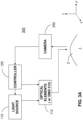
- FIG. 2A illustrates an example treatment system 200 with an active eye tracking system.
- the treatment system 200 includes an illumination system for directing photoactivating light to the cornea 2 of the eye 1.
- the illumination system includes the light source 110 and the optical elements 112 as described above.
- the light source 110 may include one or more LED's that emit UV light to photoactivate riboflavin that has been applied to the cornea 2.
- the treatment system 200 includes one or more controllers 120 to control aspects of the treatment system 200.
- the treatment system 200 includes a camera (image capture device) 252 that dynamically captures images of the eye 1 during a procedure.
- the one or more controllers 120 can process the images to detect a position of a fiducial point, such as the pupil, for the eye 1 relative to the treatment system 200. Using the position of the fiducial point as a reference, the one or more controllers 120 can determine the location of the specified areas of the cornea 2. Thus, the one or more controllers 120 can adjust the treatment system 200 to deliver the photoactivating light to the location of the specified areas.
- the camera 252 and the software e.g., computer-readable instructions stored on a non-transitory medium for processing the images and adjusting the treatment system 200 may collectively be known as a vision system.
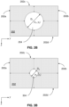
- the entire mirror array of the DMD 212 defines a maximum area 202 for delivering photoactivating light.
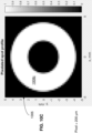
- the maximum area 202 includes boundaries 202a-d. Any part of the array of the DMD 212 can be activated to deliver photoactivating light from any portion of the maximum area 202. For instance, as shown in FIG. 2B , a part of the array of the DMD 212 can be activated to produce an illumination pattern 204 that is substantially circular and centered at a position (x c , y c ) with a diameter D 1 .
- the diameter D 1 of the illumination pattern 204 may be slightly smaller than the distance along the y-axis between the opposing boundaries 202a, b and the distance along the x-axis between the opposing boundaries 202c, d. As such, there may be space between the illumination pattern 204 and the boundaries 202a-d. This space allows the center of the illumination pattern 204 to be translated a small distance within the area 202 while maintaining the same shape with the diameter D 1 .
- another part of the array of the DMD 212 can be activated to produce the illumination pattern 204 centered at a different position ( x c + ⁇ x1 , y c + ⁇ y1 ), where ⁇ x1 represents possible translation along the x -axis and ⁇ y1 represents possible translation along the y-axis.
- the translation of the illumination pattern 204 within the area 202 changes the position of corresponding photoactivating light as delivered to the cornea 2.
- the one or more controllers 120 can control the DMD 212 to adjust the delivery of the photoactivating light so that it reaches specified areas of the cornea 2 to achieve desired results.
- the adjustments that the one or more controllers 120 can make with the DMD 212 are limited by the small amount of space between the illumination pattern 204 and the boundaries 202a-d. With the DMD 212 alone, the one or more controllers 120 might be unable to make sufficiently large adjustments to the position of the illumination pattern 204 within the area 202 to respond to larger eye movements. In other words, the illumination pattern 204 might reach one of the boundaries 202a-d before the illumination pattern 204 can be moved a desired distance.
- the treatment system 200 includes an electromechanical X-Y motion system 254 coupled to one or more of the optical elements 112.
- the one or more controllers 120 can control the X-Y motion system 254 to move one or more of the optical elements 112 into better mechanical alignment with the cornea 2 in response to larger eye movement.
- the X-Y motion system 254 may include electromechanical stages that can be operated to move one or more of the optical elements 112 and the corresponding photoactivating light along the x -axis and/or the y -axis.
- the treatment system 200 employs the DMD 212 for smaller adjustments and the X-Y motion system 254 for larger adjustments in response to varying amounts of eye movement.
- FIG. 3A illustrates an example treatment system 300 with an alternative active eye tracking system.
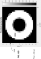
- the treatment system 300 does not employ the X-Y motion system 254. Rather, the treatment system 300 uses a DMD 312 to make substantially all desired adjustments digitally. Similar to the DMD 212 above, the entire mirror array in the DMD 312 defines the same maximum area 202 for delivering photoactivating light as shown in FIG. 3B .
- the maximum area 202 includes the same boundaries 202a-d. Any part of the array of the DMD 312 can be activated to deliver light from any portion of this maximum area 202.
- the DMD 312 delivers an illumination pattern 304 that is significantly smaller than the illumination pattern 204.
- FIGS. 2B, 3B A comparison of FIGS. 2B, 3B demonstrates the difference between the respective illumination patterns 204, 304 within the same maximum area 202.
- the smaller area illumination pattern 304 is generated by activating even less of the DMD array.
- the illumination pattern 304 is substantially circular and centered at a position ( x c , y c ) but has a diameter D 2 that is smaller than the diameter D 1 of the illumination pattern 204.
- another part of the array of the DMD 312 can be activated to produce the illumination pattern 304 centered at a different position ( x c + ⁇ x2 , y c + ⁇ y2 ) where ⁇ x2 is greater than ⁇ x1 , ⁇ y2 is greater than ⁇ y1 , and ⁇ x1 and ⁇ y1 represent possible translation along respective axes with the treatment system 200.
- the translation of the illumination pattern 304 within the area 202 changes the position of corresponding photoactivating light as applied to the cornea 2.
- Greater possible translation of the illumination pattern 304 with the DMD 312 allows greater range of adjustments for the delivery of the photoactivating light along the x-axis and/or y-axis.
- the one or more controllers 120 can employ the DMD 312 to make substantially all desired adjustments so that the photoactivating light reaches specified areas of the cornea 2 to achieve desired results.
- the treatment system 200 relies on the electromechanical X-Y motion system 254, which might employ slower motors.
- the DMD 312 can respond digitally to instructions at rates of approximately 60 Hz, so the treatment system 300 can make positional adjustments to the delivery of photoactivating light more quickly.
- FIG. 4A illustrates an initial illumination pattern 404a generated by activating a portion of the array of the DMD 312.
- the illumination pattern 404a has an initial rotational state.
- the treatment system 300 detects a rotational change in the position of the eye via the camera 252
- another portion of the array of the DMD 312 can be activated to generate an illumination pattern 404b shown in FIG. 4B .
- the illumination pattern 404b provides a geometric transformation of the initial illumination pattern 404a, with a different rotational state that responds to the rotational change in the position of the eye.
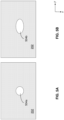
- FIG. 5A illustrates an initial illumination pattern 504a generated by activating a portion of the array of the DMD 312.
- the illumination pattern 504a is substantially circular.
- the photoactivating light from the treatment system 300 is projected as predicted onto a desired plane (e.g., x-y plane) in the cornea 2 with a corresponding substantially circular shape.
- a change in eye gaze angle and/or head position may change the angle of the desired plane in the cornea 2 and geometrically distort the projection of the photoactivating light into a shape that is different from the initial illumination pattern 504a.
- the change in eye gaze angle and/or head position may cause the illumination pattern 504a to be elongated, so that an elliptical shape is be projected onto the desired plane.
- the treatment system 300 detects a change in eye gaze angle and/or head position via the camera 252
- another portion of the array of the DMD 312 can be activated to generate an illumination pattern 504b as shown in FIG. 5B .
- the illumination pattern 504b provides a geometric transformation of the initial illumination pattern 504a, with a different shape that can compensate for the geometric distortion caused by the change in eye gaze angle and/or head position.
- the projection has precisely the desired shape.
- the projection has a substantially circular shape. In other applications, however, the projection may have other desired shapes (e.g., elliptical, etc.)
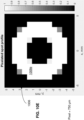
- a DMD provides an illumination pattern that is pixelated according to the array of mirrors. Because illumination patterns from the DMD are composed of a discrete number of pixels, smaller illumination patterns are composed of fewer pixels. As such, decreasing the size of an illumination pattern degrades the minimum resolvable spatial feature that can be projected onto the eye and can produce "pixelation" artifacts. As shown in FIG. 6A , the DMD 312 provides a maximum illumination area 602 defined by a plurality pixels 602a. The treatment system 300 can activate a subset of these pixels to produce a smaller illumination pattern that allows a greater range of positional adjustments. For instance, FIG.
- 602a illustrates the boundary (outline) of a desired illumination pattern 606. Due to the size of the desired illumination pattern 606, however, only pixels 604a fit substantially within the desired illumination pattern 606. If only the pixels 604a are activated, portions of the desired illumination pattern 606 remain unfilled. If pixels 604b are activated to fill the remaining portions of the desired illumination pattern 606, however, the resulting illumination pattern does not have the desired shape. In either case, the resulting illumination pattern does not have smoothed edges that correspond to the desired illumination pattern 606.
- the example of FIG. 6A demonstrates, for a given DMD array size, a tradeoff between the range of possible adjustments for active eye tracking with a DMD and resolution for achieving a desired illumination pattern.
- FIG. 6B illustrates an approach for resolving the pixilation artifact illustrated by FIG. 6A and producing an illumination pattern with smoother edges that correspond to the desired illumination pattern 606.
- the one or more controllers 120 can operate the DMD 312 to dither the pixels 604b at a rapid rate during the procedure.
- the pixels 604b can be alternately activated every second update cycle for the DMD 312.
- the total dose of photoactivating light delivered by the pixels 604b when dithered during a procedure is less than activating the pixels 604b for the entire duration of the procedure.
- dithering can be applied to provide a smoother illumination pattern that more closely approximates the desired illumination pattern 606 and the corresponding dose of photoactivating light.
- FIG. 6C illustrates another approach for smoothing out the pixilation artifact illustrated by FIG. 6A .
- dithering can be applied by alternately shifting a base shape defined by the pixels 604a shown in FIG. 6A by +/- 1 pixel along the x-axis or the y-axis at interleaved time points.
- the DMD 312 is operated to translate the base shape by one pixel in the positive-y direction (from the position shown in FIG. 6A ) to include boundaries defined partially by the pixels 608a.
- the DMD 312 is operated to translate the base shape by one pixel in the positive-x direction (from the position shown in FIG.
- the DMD 312 is operated to translate the base shape by one pixel in the negative-y direction (from the position shown in FIG. 6A ) to include boundaries defined partially by the pixels 608c.
- the DMD 312 is operated to translate the base shape by one pixel in the negative-x direction (from the position shown in FIG. 6A ) to include boundaries defined partially by the pixels 608d.
- the maximum acceptable pixel size for a DMD and optimal parameters for the embodiments above can be determined by biomechanical modeling of the response of the cornea to a cross-linking procedure.
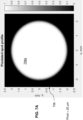
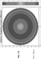
- FIGS. 7A-F illustrate the use of increasing pixel size for delivering a substantially circular UV illumination pattern 706 with a diameter of approximately 4 mm.
- the illumination pattern 706 may be employed, for instance, to generate a corresponding area of cross-linking activity in the cornea to treat myopia.
- the illumination pattern 706 is defined by pixels 708a, which are 25 ⁇ m ⁇ 25 ⁇ m in size.
- the illumination pattern 706 is defined by pixels 708b, which are 100 ⁇ m ⁇ 100 ⁇ m in size.
- the illumination pattern 706 is defined by pixels 708c, which are 200 ⁇ m ⁇ 200 ⁇ m in size.
- FIG. 7A the illumination pattern 706 is defined by pixels 708a, which are 25 ⁇ m ⁇ 25 ⁇ m in size.
- the illumination pattern 706 is defined by pixels 708b, which are 100 ⁇ m ⁇ 100 ⁇ m in size.
- the illumination pattern 706 is defined by pixels 708c, which are 200 ⁇ m ⁇ 200 ⁇ m in
- the illumination pattern 706 is defined by pixels 708d, which are 400 ⁇ m ⁇ 400 ⁇ m in size.
- the illumination pattern 706 is defined by pixels 708e, which are 750 ⁇ m ⁇ 750 ⁇ m in size.
- the illumination pattern 706 is defined by pixels 708f, which are 1000 ⁇ m ⁇ 1000 ⁇ m in size. The effects of eye motion on the illumination pattern 706 are modeled in FIGS. 7A-F with a 100 ⁇ m blurring function along the edge of the illumination pattern 706.
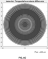
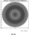
- FIGS. 8A-F illustrate modeled changes (from pre-treatment to post-treatment) in tangential curvature of the anterior cornea following cross-linking treatments using increasing pixel size for delivering the UV illumination pattern 706 as shown in FIGS. 7A-F , respectively.
- FIG. 8A illustrates the results when the illumination pattern 706 is defined by the pixels 708a (25 ⁇ m x 25 ⁇ m).
- FIG. 8B illustrates the results when the illumination pattern 706 is defined by the pixels 708b (100 ⁇ m x 100 ⁇ m).
- FIG. 8C illustrates the results when the illumination pattern 706 is defined by the pixels 708c (200 ⁇ m ⁇ 200 ⁇ m).
- FIG. 8A illustrates the results when the illumination pattern 706 is defined by the pixels 708a (25 ⁇ m x 25 ⁇ m).
- FIG. 8B illustrates the results when the illumination pattern 706 is defined by the pixels 708b (100 ⁇ m x 100 ⁇ m).
- FIG. 8C illustrates
- FIG. 8D illustrates the results when the illumination pattern 706 is defined by the pixels 708d (400 ⁇ m ⁇ 400 ⁇ m).
- FIG. 8E illustrates the results when the illumination pattern 706 is defined by the pixels 708e (750 ⁇ m ⁇ 750 ⁇ m).
- FIG. 8F illustrates the results when the illumination pattern 706 is defined by the pixels 708f (1000 ⁇ m ⁇ 1000 ⁇ m).
- TABLE 1 illustrates the change in keratometry (D) over the central 3 mm area for various pixel sizes. TABLE 1 Pixel size, ⁇ m Keratometry change, D 10 -1.62 25 -1.62 50 -1.62 250 -1.62 400 -1.61 500 -1.60 750 -1.61 1000 -1.56 1500 -1.47
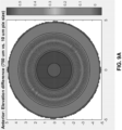
- FIGS. 9A-B illustrate a modeled difference between the results of two cross-linking treatments using a larger pixel and a smaller pixel, respectively, for delivering a substantially circular UV illumination pattern.
- the larger pixel is 750 ⁇ m ⁇ 750 ⁇ m in size
- the smaller pixel is 10 ⁇ m ⁇ 10 ⁇ m in size.
- FIG. 9A illustrates the resulting elevation ( ⁇ m) of the anterior cornea after using the larger pixel minus the resulting elevation ( ⁇ m) in the anterior cornea after using the smaller pixel.
- FIG. 9B illustrates the resulting tangential curvature (D) of the anterior cornea after using the larger pixel minus the tangential curvature (D) of the anterior cornea after using the smaller pixel.
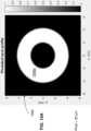
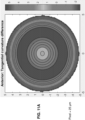
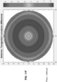
- FIGS. 10A-F illustrate the use of increasing pixel size for delivering a substantially annular UV illumination pattern 1006.
- the illumination pattern 1006 has an inner diameter of approximately 4 mm and an outer diameter of approximately 8.5 mm.
- the illumination pattern 1006 may be employed, for instance, to generate a corresponding area of cross-linking activity in the cornea to treat hyperopia or presbyopia.
- the illumination pattern 1006 is defined by pixels 1008a, which are 25 ⁇ m ⁇ 25 ⁇ m in size.
- the illumination pattern 1006 is defined by pixels 1008b, which are 100 ⁇ m ⁇ 100 ⁇ m in size.
- FIG. 10A the illumination pattern 1006 is defined by pixels 1008a, which are 25 ⁇ m ⁇ 25 ⁇ m in size.
- the illumination pattern 1006 is defined by pixels 1008b, which are 100 ⁇ m ⁇ 100 ⁇ m in size.
- the illumination pattern 1006 is defined by pixels 1008c, which are 200 ⁇ m ⁇ 200 ⁇ m in size.
- the illumination pattern 1006 is defined by pixels 1008d, which are 400 ⁇ m ⁇ 400 ⁇ m in size.
- the illumination pattern 1006 is defined by pixels 1008e, which are 750 ⁇ m ⁇ 750 ⁇ m in size.
- the illumination pattern 1006 is defined by pixels 1008f, which are 1000 ⁇ m ⁇ 1000 ⁇ m in size. The effects of eye motion on the illumination pattern 1006 are modeled in FIGS. 10A-F with a 100 ⁇ m blurring function along the edge of the illumination pattern 1006.
- FIGS. 11A-F illustrate modeled changes (from pre-treatment to post-treatment) in tangential curvature of the anterior cornea following cross-linking treatments using increasing pixel size for delivering the UV illumination pattern 1006 as shown in FIGS. 10A-F , respectively.
- FIG. 11A illustrates the results when the illumination pattern 1006 is defined by the pixels 1008a (25 ⁇ m ⁇ 25 ⁇ m).
- FIG. 11B illustrates the results when the illumination pattern 1006 is defined by the pixels 1008b (100 ⁇ m ⁇ 100 ⁇ m).
- FIG. 11C illustrates the results when the illumination pattern 1006 is defined by the pixels 1008c (200 ⁇ m ⁇ 200 ⁇ m).
- FIG. 11A illustrates the results when the illumination pattern 1006 is defined by the pixels 1008a (25 ⁇ m ⁇ 25 ⁇ m).
- FIG. 11B illustrates the results when the illumination pattern 1006 is defined by the pixels 1008b (100 ⁇ m ⁇ 100 ⁇ m).
- FIG. 11C illustrates
- FIG. 11D illustrates the results when the illumination pattern 1006 is defined by the pixels 1008d (400 ⁇ m ⁇ 400 ⁇ m).
- FIG. 11E illustrates the results when the illumination pattern 1006 is defined by the pixels 1008e (750 ⁇ m ⁇ 750 ⁇ m).
- FIG. 11F illustrates the results when the illumination pattern 1006 is defined by the pixels 1008f (1000 ⁇ m ⁇ 1000 ⁇ m).
- TABLE 2 illustrates the change in keratometry (D) over the central 3 mm area for various pixel sizes. TABLE 2 Pixel size, ⁇ m Keratometry change, D 10 1.09 200 1.09 400 1.07 750 1.03 1000 1.01 1500 0.87
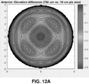
- FIGS. 12A-B illustrate a modeled difference between the results of two cross-linking treatments using a larger pixel and a smaller pixel, respectively, for delivering a substantially annular UV illumination pattern.
- the larger pixel is 750 ⁇ m ⁇ 750 ⁇ m in size
- the smaller pixel is 10 ⁇ m ⁇ 10 ⁇ m in size.
- FIG. 12A illustrates the resulting elevation ( ⁇ m) of the anterior cornea after using the larger pixel minus the resulting elevation ( ⁇ m) in the anterior cornea after using the smaller pixel.
- FIG. 12B illustrates the resulting tangential curvature (D) of the anterior cornea after using the larger pixel minus the tangential curvature (D) of the anterior cornea after using the smaller pixel.
- embodiments above may involve the use of a DMD device, other embodiments may employ any type of programmable spatial light modulator to achieve similar results.
- embodiments may employ a liquid crystal microdisplay, which is transmissive or reflective.
- Spatial light modulators that impart a polarization change can be used in conjunction with a fixed polarizer to achieve similar results.
- Transmissive implementations may also have additional advantages with respect to overall system size.
- embodiments employ a purely digital means for eye tracking that can be used with an illumination system to perform corneal cross-linking.
- the embodiments do not require electromechanical motion systems (e.g., for adjustments along an x-y plane) to keep the beam photoactivating light aligned with desired area of the subject's eye.
- electromechanical motion systems e.g., for adjustments along an x-y plane
- this allows the cost and complexity of treatment systems to be significantly reduced.
- the system allows for increased response time relative to other systems, adjustments to rotational movement of the eye, and compensation for geometric distortions caused by change in eye gaze angle and/or head movement.
- controllers may be implemented as a combination of hardware and software elements.
- the hardware aspects may include combinations of operatively coupled hardware components including microprocessors, logical circuitry, communication/networking ports, digital filters, memory, or logical circuitry.
- the controller may be adapted to perform operations specified by a computer-executable code, which may be stored on a computer readable medium.
- the controller may be a programmable processing device, such as an external conventional computer or an on-board field programmable gate array (FPGA) or digital signal processor (DSP), that executes software, or stored instructions.
- FPGA field programmable gate array
- DSP digital signal processor
- physical processors and/or machines employed by embodiments of the present disclosure for any processing or evaluation may include one or more networked or non-networked general purpose computer systems, microprocessors, field programmable gate arrays (FPGA's), digital signal processors (DSP's), micro-controllers, and the like, programmed according to the teachings of the example embodiments of the present disclosure, as is appreciated by those skilled in the computer and software arts.
- the physical processors and/or machines may be externally networked with image capture device(s) (e.g., the camera 252), or may be integrated to reside within the image capture device.
- image capture device(s) e.g., the camera 252
- Appropriate software can be readily prepared by programmers of ordinary skill based on the teachings of the example embodiments, as is appreciated by those skilled in the software art.
- the devices and subsystems of the example embodiments can be implemented by the preparation of application-specific integrated circuits or by interconnecting an appropriate network of conventional component circuits, as is appreciated by those skilled in the electrical art(s).
- the example embodiments are not limited to any specific combination of hardware circuitry and/or software.
- the example embodiments of the present disclosure may include software for controlling the devices and subsystems of the example embodiments, for driving the devices and subsystems of the example embodiments, for enabling the devices and subsystems of the example embodiments to interact with a human user, and the like.
- software can include, but is not limited to, device drivers, firmware, operating systems, development tools, applications software, and the like.
- Such computer readable media further can include the computer program product of an embodiment of the present disclosure for performing all or a portion (if processing is distributed) of the processing performed in implementations.
- Computer code devices of the example embodiments of the present disclosure can include any suitable interpretable or executable code mechanism, including but not limited to scripts, interpretable programs, dynamic link libraries (DLLs), Java classes and applets, complete executable programs, and the like. Moreover, parts of the processing of the example embodiments of the present disclosure can be distributed for better performance, reliability, cost, and the like.
- interpretable or executable code mechanism including but not limited to scripts, interpretable programs, dynamic link libraries (DLLs), Java classes and applets, complete executable programs, and the like.
- Computer-readable media may include, for example, a floppy disk, a flexible disk, hard disk, magnetic tape, any other suitable magnetic medium, a CD-ROM, CDRW, DVD, any other suitable optical medium, punch cards, paper tape, optical mark sheets, any other suitable physical medium with patterns of holes or other optically recognizable indicia, a RAM, a PROM, an EPROM, a FLASH-EPROM, any other suitable memory chip or cartridge, a carrier wave or any other suitable medium from which a computer can read.
- a floppy disk a flexible disk, hard disk, magnetic tape, any other suitable magnetic medium, a CD-ROM, CDRW, DVD, any other suitable optical medium, punch cards, paper tape, optical mark sheets, any other suitable physical medium with patterns of holes or other optically recognizable indicia, a RAM, a PROM, an EPROM, a FLASH-EPROM, any other suitable memory chip or cartridge, a carrier wave or any other suitable medium from which a computer can read.
Landscapes
- Health & Medical Sciences (AREA)
- Ophthalmology & Optometry (AREA)
- Veterinary Medicine (AREA)
- Heart & Thoracic Surgery (AREA)
- Vascular Medicine (AREA)
- Life Sciences & Earth Sciences (AREA)
- Animal Behavior & Ethology (AREA)
- General Health & Medical Sciences (AREA)
- Public Health (AREA)
- Engineering & Computer Science (AREA)
- Biomedical Technology (AREA)
- Nuclear Medicine, Radiotherapy & Molecular Imaging (AREA)
- Surgery (AREA)
- Physics & Mathematics (AREA)
- Optics & Photonics (AREA)
- Electromagnetism (AREA)
- Eye Examination Apparatus (AREA)
- Prostheses (AREA)
- Measurement Of The Respiration, Hearing Ability, Form, And Blood Characteristics Of Living Organisms (AREA)
- Radiation-Therapy Devices (AREA)
- Pharmaceuticals Containing Other Organic And Inorganic Compounds (AREA)
- Medicines That Contain Protein Lipid Enzymes And Other Medicines (AREA)
Claims (8)
- Système pour appliquer un traitement de réticulation à une cornée d'un œil, comprenant :une source de lumière configurée pour émettre une lumière de photoactivation ;un modulateur spatial de lumière configuré pour recevoir la lumière de photoactivation provenant de la source de lumière et pour fournir un éclairage pixélisé avec la lumière de photoactivation, le modulateur spatial de lumière définissant une aire maximale pour l'éclairage pixélisé ; etun dispositif de commande configuré pour amener le modulateur spatial de lumière à projeter un premier éclairage pixélisé sur la cornée pour générer une activité de réticulation dans une aire de traitement en photoactivant un agent de réticulation appliqué à une aire de traitement, le premier éclairage pixélisé présentant une aire qui est plus petite que l'aire maximale définie par le modulateur spatial de lumière,dans lequel le système est en outre configuré pour détecter un changement d'angle de regard et/ou de position de tête, et en réponse au changement d'angle de regard et/ou de position de tête, le dispositif de commande est configuré pour commander le modulateur spatial de lumière afin de projeter un second éclairage pixélisé qui est une transformation géométrique du premier éclairage pixélisé pour compenser une distorsion géométrique provoquée par le changement d'angle de regard et/ou de position de tête, et de projeter le second éclairage pixélisé vers l'aire de traitement pour continuer la photoactivation de l'agent de réticulation appliqué à l'aire de traitement.
- Système selon la revendication 1, dans lequel le modulateur spatial de lumière est un dispositif numérique à micro-miroirs (DMD), le DMD incluant une pluralité de miroirs agencés en un réseau, la pluralité de miroirs étant configurée pour réfléchir sélectivement la lumière de photoactivation provenant de la source de lumière afin de fournir l'éclairage pixélisé, la pluralité de miroirs définissant l'aire maximale pour l'éclairage pixélisé, le dispositif de commande déterminant un premier sous-ensemble des miroirs pour fournir le premier éclairage pixélisé et un second sous-ensemble des miroirs pour fournir le second éclairage pixélisé.
- Système selon la revendication 1, comprenant en outre un dispositif de capture d'image configuré pour capturer des images de la cornée, dans lequel le dispositif de commande est configuré pour : (i) recevoir des informations à partir du dispositif de capture d'image concernant les images de la cornée et (ii) détecter le changement d'angle de regard et/ou de position de la tête en fonction des informations en provenance du dispositif de capture d'image.
- Système selon la revendication 1, dans lequel le modulateur de lumière spatial inclut des limites définissant l'aire maximale pour l'éclairage pixélisé, le premier éclairage pixélisé est centré dans une première position à l'intérieur des limites, et le second éclairage pixélisé est centré dans une seconde position à l'intérieur des limites, la seconde position étant différente de la première position.
- Système selon la revendication 4, dans lequel le premier éclairage pixélisé et le second éclairage pixélisé présentent la même forme et la même taille.
- Système selon la revendication 1, dans lequel le premier éclairage pixélisé et le second éclairage pixélisé présentent une forme différente.
- Système selon la revendication 1, dans lequel la transformation géométrique fait tourner le premier éclairage pixélisé pour produire le second éclairage pixélisé.
- Système selon la revendication 1, dans lequel le dispositif de commande le modulateur spatial de lumière pour projeter le premier éclairage pixélisé sur un plan de la cornée selon la forme et la taille souhaitées, le changement de la position du regard et/ou de la tête implique un mouvement du plan de la cornée, et le dispositif de commande le modulateur spatial de lumière pour projeter le second éclairage pixélisé sur le plan de la cornée afin de produire la forme et la taille souhaitées.
Priority Applications (2)
| Application Number | Priority Date | Filing Date | Title |
|---|---|---|---|
| EP24177815.8A EP4397287A3 (fr) | 2018-03-05 | 2019-03-05 | Système de suivi oculaire pendant un traitement oculaire |
| EP23195723.4A EP4260834B1 (fr) | 2018-03-05 | 2019-03-05 | Système de suivi oculaire pendant un traitement oculaire |
Applications Claiming Priority (2)
| Application Number | Priority Date | Filing Date | Title |
|---|---|---|---|
| US201862638621P | 2018-03-05 | 2018-03-05 | |
| PCT/US2019/020839 WO2019173403A1 (fr) | 2018-03-05 | 2019-03-05 | Systèmes d'oculométrie pendant un traitement oculaire |
Related Child Applications (3)
| Application Number | Title | Priority Date | Filing Date |
|---|---|---|---|
| EP24177815.8A Division EP4397287A3 (fr) | 2018-03-05 | 2019-03-05 | Système de suivi oculaire pendant un traitement oculaire |
| EP23195723.4A Division EP4260834B1 (fr) | 2018-03-05 | 2019-03-05 | Système de suivi oculaire pendant un traitement oculaire |
| EP23195723.4A Division-Into EP4260834B1 (fr) | 2018-03-05 | 2019-03-05 | Système de suivi oculaire pendant un traitement oculaire |
Publications (2)
| Publication Number | Publication Date |
|---|---|
| EP3761927A1 EP3761927A1 (fr) | 2021-01-13 |
| EP3761927B1 true EP3761927B1 (fr) | 2024-01-31 |
Family
ID=65818645
Family Applications (3)
| Application Number | Title | Priority Date | Filing Date |
|---|---|---|---|
| EP23195723.4A Active EP4260834B1 (fr) | 2018-03-05 | 2019-03-05 | Système de suivi oculaire pendant un traitement oculaire |
| EP24177815.8A Pending EP4397287A3 (fr) | 2018-03-05 | 2019-03-05 | Système de suivi oculaire pendant un traitement oculaire |
| EP19712376.3A Active EP3761927B1 (fr) | 2018-03-05 | 2019-03-05 | Système d'oculométrie pendant un traitement oculaire |
Family Applications Before (2)
| Application Number | Title | Priority Date | Filing Date |
|---|---|---|---|
| EP23195723.4A Active EP4260834B1 (fr) | 2018-03-05 | 2019-03-05 | Système de suivi oculaire pendant un traitement oculaire |
| EP24177815.8A Pending EP4397287A3 (fr) | 2018-03-05 | 2019-03-05 | Système de suivi oculaire pendant un traitement oculaire |
Country Status (7)
| Country | Link |
|---|---|
| US (2) | US12042433B2 (fr) |
| EP (3) | EP4260834B1 (fr) |
| JP (3) | JP7379357B2 (fr) |
| CN (2) | CN117137718A (fr) |
| AU (2) | AU2019231257B2 (fr) |
| CA (1) | CA3093065A1 (fr) |
| WO (1) | WO2019173403A1 (fr) |
Families Citing this family (3)
| Publication number | Priority date | Publication date | Assignee | Title |
|---|---|---|---|---|
| EP4260834B1 (fr) * | 2018-03-05 | 2025-05-07 | Avedro, Inc. | Système de suivi oculaire pendant un traitement oculaire |
| CN116721153A (zh) * | 2022-07-04 | 2023-09-08 | 超目科技(北京)有限公司 | 角膜交联照射位置的确定方法、装置、设备及存储介质 |
| CN117695527B (zh) * | 2023-11-14 | 2024-07-02 | 超目科技(北京)有限公司 | 一种角膜交联系统 |
Family Cites Families (155)
| Publication number | Priority date | Publication date | Assignee | Title |
|---|---|---|---|---|
| US4034750A (en) | 1975-04-22 | 1977-07-12 | Maurice Seiderman | Electrochemically linking collagen fibrils to animal tissue |
| US4712543A (en) | 1982-01-20 | 1987-12-15 | Baron Neville A | Process for recurving the cornea of an eye |
| US4665913A (en) | 1983-11-17 | 1987-05-19 | Lri L.P. | Method for ophthalmological surgery |
| US4764007A (en) | 1986-02-24 | 1988-08-16 | The United States Of America As Represented By The Secretary Of The Air Force | Glare susceptibility tester |
| GB8606821D0 (en) | 1986-03-19 | 1986-04-23 | Pa Consulting Services | Corneal reprofiling |
| US5019074A (en) | 1987-03-09 | 1991-05-28 | Summit Technology, Inc. | Laser reprofiling system employing an erodable mask |
| US4891043A (en) | 1987-05-28 | 1990-01-02 | Board Of Trustees Of The University Of Illinois | System for selective release of liposome encapsulated material via laser radiation |
| US5171318A (en) | 1987-11-09 | 1992-12-15 | Chiron Ophthalmics, Inc. | Treated corneal prosthetic device |
| US4969912A (en) | 1988-02-18 | 1990-11-13 | Kelman Charles D | Human collagen processing and autoimplant use |
| US5152759A (en) | 1989-06-07 | 1992-10-06 | University Of Miami, School Of Medicine, Dept. Of Ophthalmology | Noncontact laser microsurgical apparatus |
| US5490849A (en) | 1990-07-13 | 1996-02-13 | Smith; Robert F. | Uniform-radiation caustic surface for photoablation |
| US5779696A (en) | 1990-07-23 | 1998-07-14 | Sunrise Technologies International, Inc. | Method and apparatus for performing corneal reshaping to correct ocular refractive errors |
| US6325792B1 (en) | 1991-11-06 | 2001-12-04 | Casimir A. Swinger | Ophthalmic surgical laser and method |
| RU2086215C1 (ru) | 1992-03-17 | 1997-08-10 | Александр Иосифович Симановский | Способ определения истинного внутриглазного давления, коэффициента легкости оттока и минутного объема продуцирования камерной влаги |
| US6450641B2 (en) | 1992-06-02 | 2002-09-17 | Lasersight Technologies, Inc. | Method of corneal analysis using a checkered placido apparatus |
| JP2965101B2 (ja) | 1992-07-31 | 1999-10-18 | 株式会社ニデック | 眼科装置 |
| US5891131A (en) | 1993-02-01 | 1999-04-06 | Arizona Board Of Regents | Method and apparatus for automated simulation and design of corneal refractive procedures |
| AU6559394A (en) | 1993-04-15 | 1994-11-08 | Board Of Regents, The University Of Texas System | Raman spectrometer |
| US5461212A (en) | 1993-06-04 | 1995-10-24 | Summit Technology, Inc. | Astigmatic laser ablation of surfaces |
| AU716040B2 (en) | 1993-06-24 | 2000-02-17 | Bausch & Lomb Incorporated | Ophthalmic pachymeter and method of making ophthalmic determinations |
| US5624437A (en) | 1995-03-28 | 1997-04-29 | Freeman; Jerre M. | High resolution, high speed, programmable laser beam modulating apparatus for microsurgery |
| HU213450B (en) | 1995-04-26 | 1997-06-30 | Ladanyi Jozsef | Gel contains gelatin and process for producing it |
| US5910110A (en) | 1995-06-07 | 1999-06-08 | Mentor Ophthalmics, Inc. | Controlling pressure in the eye during surgery |
| US6520956B1 (en) | 1995-11-06 | 2003-02-18 | David Huang | Apparatus and method for performing laser thermal keratoplasty with minimized regression |
| US6033396A (en) | 1995-11-06 | 2000-03-07 | Huang; David | Apparatus and method for performing laser thermal keratoplasty with minimized regression |
| US20060149343A1 (en) | 1996-12-02 | 2006-07-06 | Palomar Medical Technologies, Inc. | Cooling system for a photocosmetic device |
| US6302876B1 (en) | 1997-05-27 | 2001-10-16 | Visx Corporation | Systems and methods for imaging corneal profiles |
| RU2130762C1 (ru) | 1997-12-10 | 1999-05-27 | Федоров Святослав Николаевич | Устройство для офтальмохирургических операций |
| US6161544A (en) | 1998-01-28 | 2000-12-19 | Keratoform, Inc. | Methods for accelerated orthokeratology |
| US20020013577A1 (en) | 1998-03-06 | 2002-01-31 | Frey Rudolph W. | Laser beam delivery and eye tracking system |
| BR9908692A (pt) | 1998-03-09 | 2001-12-04 | Ista Pharmaceuticals Inc | Uso de agentes de enrijecimento corneal emortocerotologia enzimática |
| US6188500B1 (en) | 1998-04-03 | 2001-02-13 | Psc Scanning, Inc. | Method for generating multiple scan lines in a thin scanner |
| WO1999057529A1 (fr) | 1998-05-04 | 1999-11-11 | The Board Of Regents | Spectroscopie par fluorescence et reflectance combinees |
| BR9913130A (pt) | 1998-08-19 | 2001-05-08 | Autonomous Technologies Corp | Aparelho e método para medir defeitos de visão de um olho humano |
| US6218360B1 (en) | 1998-11-19 | 2001-04-17 | The Schepens Eye Research Institute | Collagen based biomaterials and methods of preparation and use |
| US6617963B1 (en) | 1999-02-26 | 2003-09-09 | Sri International | Event-recording devices with identification codes |
| WO2000074648A2 (fr) | 1999-06-04 | 2000-12-14 | Sunrise Technologies International, Inc. | Prevention de la regression dans la keratoplastie de refraction |
| US6280436B1 (en) | 1999-08-10 | 2001-08-28 | Memphis Eye & Cataract Associates Ambulatory Surgery Center | Eye tracking and positioning system for a refractive laser system |
| JP2002058695A (ja) | 1999-09-03 | 2002-02-26 | Carl Zeiss Jena Gmbh | 眼の照射方法及び装置 |
| US6946440B1 (en) | 1999-09-15 | 2005-09-20 | Dewoolfson Bruce H | Composition for stabilizing corneal tissue during or after orthokeratology lens wear |
| US6319273B1 (en) | 1999-12-16 | 2001-11-20 | Light Sciences Corporation | Illuminating device for treating eye disease |
| US8215314B2 (en) | 2000-02-11 | 2012-07-10 | The General Hospital Corporation | Photochemical tissue bonding |
| US7331350B2 (en) | 2000-02-11 | 2008-02-19 | The General Hospital Corporation | Photochemical tissue bonding |
| US7073510B2 (en) | 2000-02-11 | 2006-07-11 | The General Hospital Corporation | Photochemical tissue bonding |
| US6394999B1 (en) | 2000-03-13 | 2002-05-28 | Memphis Eye & Cataract Associates Ambulatory Surgery Center | Laser eye surgery system using wavefront sensor analysis to control digital micromirror device (DMD) mirror patterns |
| US6949093B1 (en) | 2000-03-21 | 2005-09-27 | Minu, L.L.C. | Adjustable universal implant blank for modifying corneal curvature and methods of modifying corneal curvature therewith |
| US6494878B1 (en) | 2000-05-12 | 2002-12-17 | Ceramoptec Industries, Inc. | System and method for accurate optical treatment of an eye's fundus |
| AU2001267851A1 (en) | 2000-06-29 | 2002-01-08 | Rohto Pharmaceutical Co., Ltd. | Oxygen-containing ophthalmic composition |
| US7753943B2 (en) | 2001-02-06 | 2010-07-13 | Qlt Inc. | Reduced fluence rate PDT |
| US7044945B2 (en) | 2001-03-30 | 2006-05-16 | Sand Bruce J | Prevention of regression in thermal ciliary muscle tendinoplasty |
| US6766042B2 (en) | 2001-04-26 | 2004-07-20 | Memphis Eye & Contact Associates | System to automatically detect eye corneal striae |
| US20050149006A1 (en) | 2001-11-07 | 2005-07-07 | Peyman Gholam A. | Device and method for reshaping the cornea |
| US9155652B2 (en) | 2001-11-07 | 2015-10-13 | Gholam A. Peyman | Method for laser correction of refractive errors of an eye with a thin cornea |
| US20070142828A1 (en) | 2001-11-07 | 2007-06-21 | Minu, Llc | Method and system for altering the refractive properties of the eye |
| US20070135805A1 (en) | 2001-11-07 | 2007-06-14 | Minu Telesystems Llc | Device and method for reshaping the cornea |
| US9681942B2 (en) | 2001-11-07 | 2017-06-20 | Gholam A. Peyman | Method for prevention of rejection and sever encapsulation of a supportive or functioning implant |
| WO2003085376A2 (fr) | 2002-04-03 | 2003-10-16 | The Regents Of The University Of California | Systeme et procede de mesure quantitative ou qualitative de substances exogenes dans un tissu et d'autres matieres par mise en oeuvre d'une spectroscopie par fluorescence induite par laser |
| EP1358839B1 (fr) | 2002-04-05 | 2005-02-23 | SIS AG Surgical Instrument Systems | Dispositif et procédé de determination des valeurs de mesure géométriques d'un oeil |
| US6758564B2 (en) | 2002-06-14 | 2004-07-06 | Physical Sciences, Inc. | Line-scan laser ophthalmoscope |
| US7004902B2 (en) | 2003-03-21 | 2006-02-28 | Reichert, Inc. | Method and apparatus for measuring biomechanical characteristics of corneal tissue |
| US20110098790A1 (en) | 2009-10-26 | 2011-04-28 | Albert Daxer | Methods for treating corneal disease |
| US20050096515A1 (en) | 2003-10-23 | 2005-05-05 | Geng Z. J. | Three-dimensional surface image guided adaptive therapy system |
| DE502004009305D1 (de) | 2004-02-03 | 2009-05-20 | Iroc Ag | Ophtalmologische Vorrichtung |
| WO2005110397A1 (fr) | 2004-05-07 | 2005-11-24 | The Regents Of The University Of California | Traitement de la myopie |
| ITMI20041625A1 (it) | 2004-08-06 | 2004-11-06 | Roberto Pinelli | Apparato per la correzione della presbiopia |
| US20060135957A1 (en) | 2004-12-21 | 2006-06-22 | Dorin Panescu | Method and apparatus to align a probe with a cornea |
| US8394084B2 (en) | 2005-01-10 | 2013-03-12 | Optimedica Corporation | Apparatus for patterned plasma-mediated laser trephination of the lens capsule and three dimensional phaco-segmentation |
| US20060276777A1 (en) | 2005-04-08 | 2006-12-07 | Coroneo Minas T | Corneal shaping |
| US20060287662A1 (en) | 2005-05-26 | 2006-12-21 | Ntk Enterprises, Inc. | Device, system, and method for epithelium protection during cornea reshaping |
| WO2007001926A2 (fr) | 2005-06-24 | 2007-01-04 | Hyperbranch Medical Technology, Inc. | Matériaux d'obturation par hydrogel à faible gonflement pour la réparation des blessures |
| DE102005035870A1 (de) | 2005-07-30 | 2007-02-01 | Carl Zeiss Meditec Ag | Optisches Scan-System |
| US7292347B2 (en) | 2005-08-01 | 2007-11-06 | Mitutoyo Corporation | Dual laser high precision interferometer |
| US20070048340A1 (en) | 2005-08-31 | 2007-03-01 | Searete Llc, A Limited Liability Corporation Of The State Of Delaware | Multi step patterning of a skin surface |
| EP1779891A1 (fr) | 2005-10-28 | 2007-05-02 | Abdula Kurkayev | Méthode d'activation d'un photosensibilisateur |
| CA2621719C (fr) | 2005-10-31 | 2014-05-20 | Crs & Associates | Procede et appareil pour mesurer les caracteristiques de deformation d'un objet |
| DE102005056958A1 (de) | 2005-11-29 | 2007-06-06 | Rowiak Gmbh | Verfahren und Vorrichtung zum Bearbeiten eines Werkstücks |
| WO2007082127A2 (fr) | 2006-01-05 | 2007-07-19 | El Hage Sami G | Thérapie de combinaison pour ckrtm durable |
| US8182471B2 (en) | 2006-03-17 | 2012-05-22 | Amo Manufacturing Usa, Llc. | Intrastromal refractive correction systems and methods |
| EP2004209B1 (fr) | 2006-04-13 | 2013-07-24 | Euclid Systems Corporation | Composition et procédé de stabilisation de tissu de la cornée après une chirurgie réfractive |
| WO2007122615A2 (fr) | 2006-04-20 | 2007-11-01 | Xceed Imaging Ltd. | Système entièrement optique et procédé destinés à produire des images présentant une profondeur de focalisation étendue |
| US20100028407A1 (en) | 2006-04-27 | 2010-02-04 | University Of Louisville Research Foundation, Inc. | Layered bio-adhesive compositions and uses thereof |
| CA2653309C (fr) | 2006-05-26 | 2013-11-19 | The Cleveland Clinic Foundation | Procede de mesure de proprietes biomecaniques dans un oeil |
| WO2007143111A2 (fr) | 2006-06-01 | 2007-12-13 | University Of Southern California | Procédé et appareil destinés à guider une chirurgie cornéenne au laser avec mesures optiques |
| DE102006030219A1 (de) | 2006-06-30 | 2008-01-03 | Iroc Ag | Bestrahlungssystem für medizinische Anwendungen |
| US20080015660A1 (en) | 2006-07-13 | 2008-01-17 | Priavision, Inc. | Method And Apparatus For Photo-Chemical Oculoplasty/Keratoplasty |
| US20080063627A1 (en) | 2006-09-12 | 2008-03-13 | Surmodics, Inc. | Tissue graft materials containing biocompatible agent and methods of making and using same |
| US8414911B2 (en) | 2006-10-24 | 2013-04-09 | The Regents Of The University Of California | Photochemical therapy to affect mechanical and/or chemical properties of body tissue |
| WO2008070185A2 (fr) | 2006-12-06 | 2008-06-12 | The Trustees Of Columbia University In The City Of New York | Procédé de stabilisation de tissu oculaire humain par réaction avec du nitrite et des agents associés tels que des composés nitro |
| US20080139671A1 (en) | 2006-12-07 | 2008-06-12 | Priavision, Inc. | Method and material for in situ corneal structural augmentation |
| US9566030B2 (en) | 2007-02-01 | 2017-02-14 | Ls Biopath, Inc. | Optical system for detection and characterization of abnormal tissue and cells |
| WO2008124009A2 (fr) | 2007-04-02 | 2008-10-16 | The Cleveland Clinic Foundation | Procédés de traitement du glaucome |
| WO2008137637A2 (fr) | 2007-05-04 | 2008-11-13 | The General Hospital Corporation | Procédés, agencements et systèmes pour obtenir des informations associées à un échantillon à l'aide d'une microscopie optique |
| EP2227197A4 (fr) | 2007-12-05 | 2011-06-22 | Avedro Inc | Système de thérapie oculaire |
| US20100057060A1 (en) | 2007-12-07 | 2010-03-04 | Seros Medical, Llc | In Situ UV/Riboflavin Ocular Treatment System |
| US20090149923A1 (en) | 2007-12-07 | 2009-06-11 | 21X Corporation Dba Priavision, Inc. | Method for equi-dosed time fractionated pulsed uva irradiation of collagen/riboflavin mixtures for ocular structural augmentation |
| WO2009114513A2 (fr) | 2008-03-14 | 2009-09-17 | Euclid Systems Corporation | Irradiation d'ultraviolet pour traiter des troubles de faiblesse cornéenne |
| WO2009146151A2 (fr) | 2008-04-04 | 2009-12-03 | Forsight Labs, Llc | Dispositifs de greffe de la cornée et procédés |
| US9125735B2 (en) | 2008-04-04 | 2015-09-08 | Forsight Labs, Llc | Method of correcting vision using corneal onlays |
| US20090275929A1 (en) | 2008-04-30 | 2009-11-05 | Amo Development, Llc | System and method for controlling measurement in an eye during ophthalmic procedure |
| US7898656B2 (en) | 2008-04-30 | 2011-03-01 | The General Hospital Corporation | Apparatus and method for cross axis parallel spectroscopy |
| WO2010011119A1 (fr) | 2008-07-22 | 2010-01-28 | Choza Remero Andres Abelino | Solution ophtalmique pour épaissir les cornées |
| WO2010015255A1 (fr) | 2008-08-08 | 2010-02-11 | Glostrup Hospital | Système et procédé pour traiter des troubles associés au cristallin |
| RU2391078C2 (ru) | 2008-08-14 | 2010-06-10 | Сергей Игоревич Анисимов | Способ лечения кератоконуса воздействием ультрафиолетового излучения и устройство для его осуществления (варианты) |
| IT1393402B1 (it) | 2008-08-28 | 2012-04-20 | Sooft Italia Spa | Uso di enhancer eventualmente con riboflavina, nonche' relative composizioni oftalmiche per cross-linking corneale del cheratocono o di altre patologie ectasiche corneali |
| DE102008046834A1 (de) | 2008-09-11 | 2010-03-18 | Iroc Ag | Steuerprogramm zum Steuern elektromagnetischer Strahlung für eine Quervernetzung von Augengewebe |
| US20100082018A1 (en) | 2008-09-26 | 2010-04-01 | Daryus Panthakey | Method and system for reshaping the cornea |
| US8366689B2 (en) | 2008-09-30 | 2013-02-05 | Avedro, Inc. | Method for making structural changes in corneal fibrils |
| US8226232B2 (en) | 2008-12-17 | 2012-07-24 | Technion Research And Development Foundation, Ltd. | System and method for fast retinal imaging |
| US20120059439A1 (en) | 2009-02-12 | 2012-03-08 | University Of Rochester | Aberration control by corneal collagen crosslinking combined with beam-shaping technique |
| WO2010093772A1 (fr) | 2009-02-12 | 2010-08-19 | Alcon Research, Ltd. | Procédé et appareil d'imagerie de la surface oculaire |
| US20100318017A1 (en) | 2009-06-11 | 2010-12-16 | Lewis Scott E | Method of improving vision using contact lenses and corneal collagen crosslinking |
| EP2464387A4 (fr) | 2009-08-12 | 2013-05-15 | Seros Medical Llc | Solution d'eau deutérée et de riboflavine pour des durées de vie prolongées d'oxygène singulet dans le traitement du tissu oculaire et procédé d'utilisation |
| US8518028B2 (en) | 2009-09-30 | 2013-08-27 | Abbott Medical Optics Inc. | Methods for enhancing accommodation of a natural lens of an eye |
| WO2011050164A1 (fr) * | 2009-10-21 | 2011-04-28 | Avedro, Inc. | Traitement oculaire |
| US20130245536A1 (en) | 2009-10-21 | 2013-09-19 | Avedro, Inc. | Systems and methods for corneal cross-linking with pulsed light |
| JP6377906B2 (ja) * | 2010-03-19 | 2018-08-22 | アヴェドロ・インコーポレーテッドAvedro,Inc. | 眼治療を適用およびモニターするためのシステム |
| US20120215155A1 (en) | 2010-03-19 | 2012-08-23 | Avedro Inc. | Controlled cross-linking initiation and corneal topography feedback systems for directing cross-linking |
| US20110288466A1 (en) | 2010-04-13 | 2011-11-24 | Avedro, Inc. | Systems and methods for activating cross-linking in an eye |
| EP2907490A1 (fr) | 2010-04-21 | 2015-08-19 | IROC Innocross AG | Dispositif de réticulation d'un tissu oculaire à l'aide d'un rayonnement électromagnétique |
| DE102010020194B4 (de) | 2010-05-07 | 2022-09-08 | Carl Zeiss Meditec Ag | Vorrichtung zur Stabilisierung der Augenhornhaut |
| KG1376C1 (en) | 2010-05-31 | 2011-08-30 | M A Medvedev | Method for keratoconus treatment |
| IT1400982B1 (it) | 2010-07-05 | 2013-07-05 | Pinelli | Collirio osmotico trans-epiteliale per la cura del cheratocono. |
| US20120083772A1 (en) | 2010-09-30 | 2012-04-05 | Curveright Llc | Corneal treatment system and method |
| US9622911B2 (en) | 2010-09-30 | 2017-04-18 | Cxl Ophthalmics, Llc | Ophthalmic treatment device, system, and method of use |
| US8111394B1 (en) | 2011-04-01 | 2012-02-07 | IsoSpec Technologies, LP | Raman spectrometer for monitoring traces of dissolved organic and inorganic substances |
| RU2456971C1 (ru) | 2011-04-19 | 2012-07-27 | Федеральное государственное учреждение "Межотраслевой научно-технический комплекс "Микрохирургия глаза" имени академика С.Н. Федорова Федерального агентства по высокотехнологичной медицинской помощи" | Способ лечения прогрессирующего кератоконуса |
| WO2012145159A1 (fr) * | 2011-04-20 | 2012-10-26 | Avedro, Inc. | Début de réticulation contrôlée et système de rétroaction topographique cornéenne |
| EP3838123A1 (fr) | 2011-04-29 | 2021-06-23 | The General Hospital Corporation | Procédés et agencements pour obtenir des informations et fournir une analyse de tissus biologiques |
| WO2012158991A2 (fr) | 2011-05-18 | 2012-11-22 | Avedro, Inc. | Application contrôlée d'un agent réticulant |
| WO2012162529A1 (fr) | 2011-05-24 | 2012-11-29 | Avedro, Inc. | Systèmes et procédés de remodelage d'un élément d'un œil |
| US10813791B2 (en) | 2011-06-02 | 2020-10-27 | University Of Rochester | Method for modifying the refractive index of ocular tissues and applications thereof |
| WO2012167260A2 (fr) * | 2011-06-02 | 2012-12-06 | Avedro, Inc. | Systèmes et procédés de surveillance de l'administration d'un agent photo-actif basé sur le temps ou de la présence d'un marqueur photo-actif |
| WO2012174453A2 (fr) | 2011-06-15 | 2012-12-20 | Sybotics, Llc | Systèmes et procédés pour imagerie d'iris binoculaire |
| CN202223422U (zh) * | 2011-08-25 | 2012-05-23 | 苏州新视野光电技术有限公司 | 一种激光治疗远视手术系统 |
| JP2013052988A (ja) | 2011-09-06 | 2013-03-21 | Canon Inc | 印刷装置、印刷装置の制御方法及びプログラム |
| EP2760397A4 (fr) | 2011-10-02 | 2015-06-24 | Avedro Inc | Systèmes et procédés pour l'application et la surveillance d'un traitement oculaire |
| US20150088231A1 (en) | 2012-03-28 | 2015-03-26 | Cxl Ophthalmics, Llc | Ocular treatment system and method using red and gold phototherapy |
| ES2986057T3 (es) | 2012-03-29 | 2024-11-08 | Epion Therapeutics Inc | Composiciones y métodos para tratar o prevenir enfermedades asociadas al estrés oxidativo |
| EP2830627B1 (fr) | 2012-03-29 | 2024-05-01 | Epion Therapeutics, Inc. | Solutions de traitement oculaire, dispositifs d'administration et procédés améliorant l'administration |
| WO2013148895A1 (fr) | 2012-03-29 | 2013-10-03 | Cxl Ophthalmics, Llc | Système de réticulation oculaire et procédé de scellement étanche de plaies cornéennes |
| EP2872081B2 (fr) | 2012-07-16 | 2025-07-16 | Avedro, Inc. | Systèmes pour une réticulation cornéenne avec une lumière pulsée |
| DE102013211854B4 (de) | 2013-06-21 | 2017-01-05 | Universität Rostock | Verfahren und Vorrichtung zur Bestimmung einer spektralen Änderung von gestreutem Licht |
| CN105682620B (zh) * | 2013-10-30 | 2019-02-22 | 视乐有限公司 | 交联控制 |
| KR102545628B1 (ko) * | 2014-10-27 | 2023-06-20 | 아베드로 인코퍼레이티드 | 눈의 교차-결합 처리를 위한 시스템 및 방법 |
| KR102149590B1 (ko) | 2015-12-03 | 2020-08-28 | 아베드로 인코퍼레이티드 | 마스크 장치로 눈을 치료하기 위한 시스템 및 방법 |
| US10222465B2 (en) * | 2015-12-29 | 2019-03-05 | Geophysical Survey Systems, Inc. | Magnetic field detector and ground-penetrating radar device with merged display |
| WO2017180851A1 (fr) | 2016-04-13 | 2017-10-19 | Avedro, Inc. | Systèmes et procédés d'administration de médicaments à un œil |
| WO2017184717A1 (fr) * | 2016-04-19 | 2017-10-26 | Avedro, Inc. | Systèmes et procédés de traitements d'un œil par réticulation |
| CN106264855B (zh) * | 2016-10-13 | 2018-11-06 | 清华大学深圳研究生院 | 一种用于治疗角膜组织疾病的装置 |
| CN106693205B (zh) * | 2016-12-23 | 2019-04-19 | 中国科学院苏州生物医学工程技术研究所 | 核黄素紫外胶联机构 |
| JP7035081B2 (ja) * | 2017-01-11 | 2022-03-14 | アヴェドロ・インコーポレーテッド | 角膜におけるクロスリンキング分布及び/又は角膜の構造的特徴を決定するためのシステム及び方法 |
| EP4260834B1 (fr) * | 2018-03-05 | 2025-05-07 | Avedro, Inc. | Système de suivi oculaire pendant un traitement oculaire |
| WO2019173762A1 (fr) * | 2018-03-08 | 2019-09-12 | Avedro, Inc. | Micro-dispositifs pour le traitement d'un œil |
| CA3113120A1 (fr) * | 2018-10-09 | 2020-04-16 | Avedro, Inc. | Systemes de photoactivation et methodes pour traitements de reticulation corneenne |
| US11642244B2 (en) * | 2019-08-06 | 2023-05-09 | Avedro, Inc. | Photoactivation systems and methods for corneal cross-linking treatments |
-
2019
- 2019-03-05 EP EP23195723.4A patent/EP4260834B1/fr active Active
- 2019-03-05 AU AU2019231257A patent/AU2019231257B2/en active Active
- 2019-03-05 CA CA3093065A patent/CA3093065A1/fr active Pending
- 2019-03-05 US US16/978,694 patent/US12042433B2/en active Active
- 2019-03-05 CN CN202311162411.6A patent/CN117137718A/zh active Pending
- 2019-03-05 JP JP2020546332A patent/JP7379357B2/ja active Active
- 2019-03-05 EP EP24177815.8A patent/EP4397287A3/fr active Pending
- 2019-03-05 EP EP19712376.3A patent/EP3761927B1/fr active Active
- 2019-03-05 WO PCT/US2019/020839 patent/WO2019173403A1/fr not_active Ceased
- 2019-03-05 CN CN201980030236.0A patent/CN112533564B/zh active Active
-
2023
- 2023-11-01 JP JP2023187802A patent/JP7630591B2/ja active Active
-
2024
- 2024-07-22 US US18/779,976 patent/US20260041586A1/en active Pending
-
2025
- 2025-01-29 AU AU2025200578A patent/AU2025200578A1/en active Pending
- 2025-02-04 JP JP2025016872A patent/JP2025069356A/ja active Pending
Also Published As
| Publication number | Publication date |
|---|---|
| US20260041586A1 (en) | 2026-02-12 |
| CN112533564B (zh) | 2023-10-03 |
| JP2024001316A (ja) | 2024-01-09 |
| EP4260834B1 (fr) | 2025-05-07 |
| JP7630591B2 (ja) | 2025-02-17 |
| EP4260834A3 (fr) | 2023-12-27 |
| AU2019231257A1 (en) | 2020-10-15 |
| US20200397613A1 (en) | 2020-12-24 |
| AU2019231257B2 (en) | 2024-10-31 |
| WO2019173403A1 (fr) | 2019-09-12 |
| JP2021514776A (ja) | 2021-06-17 |
| JP7379357B2 (ja) | 2023-11-14 |
| EP4397287A3 (fr) | 2024-09-11 |
| EP4397287A2 (fr) | 2024-07-10 |
| EP3761927A1 (fr) | 2021-01-13 |
| JP2025069356A (ja) | 2025-04-30 |
| CN112533564A (zh) | 2021-03-19 |
| CA3093065A1 (fr) | 2019-09-12 |
| CN117137718A (zh) | 2023-12-01 |
| EP4260834A2 (fr) | 2023-10-18 |
| US12042433B2 (en) | 2024-07-23 |
| AU2025200578A1 (en) | 2025-02-20 |
Similar Documents
| Publication | Publication Date | Title |
|---|---|---|
| US20190365564A1 (en) | Controlled cross-linking initiation and corneal topography feedback systems for directing cross-linking | |
| US20260041586A1 (en) | Systems and methods for eye tracking during eye treatment | |
| EP2712311B1 (fr) | Début de réticulation contrôlée et système de rétroaction topographique cornéenne | |
| US20240009031A1 (en) | Micro-devices for treatment of an eye | |
| US20250387260A1 (en) | Systems and methods treating for corneal ectatic disorders | |
| JP7624433B2 (ja) | 角膜の架橋治療のための光活性化システム及び方法 | |
| WO2017184717A1 (fr) | Systèmes et procédés de traitements d'un œil par réticulation | |
| US12293513B2 (en) | Systems and methods for generating patient-specific corneal cross-linking treatment patterns | |
| JPWO2020061278A5 (fr) |
Legal Events
| Date | Code | Title | Description |
|---|---|---|---|
| STAA | Information on the status of an ep patent application or granted ep patent |
Free format text: STATUS: UNKNOWN |
|
| STAA | Information on the status of an ep patent application or granted ep patent |
Free format text: STATUS: THE INTERNATIONAL PUBLICATION HAS BEEN MADE |
|
| PUAI | Public reference made under article 153(3) epc to a published international application that has entered the european phase |
Free format text: ORIGINAL CODE: 0009012 |
|
| STAA | Information on the status of an ep patent application or granted ep patent |
Free format text: STATUS: REQUEST FOR EXAMINATION WAS MADE |
|
| 17P | Request for examination filed |
Effective date: 20201002 |
|
| AK | Designated contracting states |
Kind code of ref document: A1 Designated state(s): AL AT BE BG CH CY CZ DE DK EE ES FI FR GB GR HR HU IE IS IT LI LT LU LV MC MK MT NL NO PL PT RO RS SE SI SK SM TR |
|
| AX | Request for extension of the european patent |
Extension state: BA ME |
|
| DAV | Request for validation of the european patent (deleted) | ||
| DAX | Request for extension of the european patent (deleted) | ||
| GRAP | Despatch of communication of intention to grant a patent |
Free format text: ORIGINAL CODE: EPIDOSNIGR1 |
|
| STAA | Information on the status of an ep patent application or granted ep patent |
Free format text: STATUS: GRANT OF PATENT IS INTENDED |
|
| INTG | Intention to grant announced |
Effective date: 20230419 |
|
| RIN1 | Information on inventor provided before grant (corrected) |
Inventor name: SMIRNOV, KIKHAIL, Z. Inventor name: USHER, DAVID Inventor name: ADLER, DESMOND, CHRISTOPHER |
|
| P01 | Opt-out of the competence of the unified patent court (upc) registered |
Effective date: 20230524 |
|
| GRAJ | Information related to disapproval of communication of intention to grant by the applicant or resumption of examination proceedings by the epo deleted |
Free format text: ORIGINAL CODE: EPIDOSDIGR1 |
|
| STAA | Information on the status of an ep patent application or granted ep patent |
Free format text: STATUS: REQUEST FOR EXAMINATION WAS MADE |
|
| GRAP | Despatch of communication of intention to grant a patent |
Free format text: ORIGINAL CODE: EPIDOSNIGR1 |
|
| STAA | Information on the status of an ep patent application or granted ep patent |
Free format text: STATUS: GRANT OF PATENT IS INTENDED |
|
| INTC | Intention to grant announced (deleted) | ||
| INTG | Intention to grant announced |
Effective date: 20230915 |
|
| GRAS | Grant fee paid |
Free format text: ORIGINAL CODE: EPIDOSNIGR3 |
|
| GRAA | (expected) grant |
Free format text: ORIGINAL CODE: 0009210 |
|
| STAA | Information on the status of an ep patent application or granted ep patent |
Free format text: STATUS: THE PATENT HAS BEEN GRANTED |
|
| AK | Designated contracting states |
Kind code of ref document: B1 Designated state(s): AL AT BE BG CH CY CZ DE DK EE ES FI FR GB GR HR HU IE IS IT LI LT LU LV MC MK MT NL NO PL PT RO RS SE SI SK SM TR |
|
| REG | Reference to a national code |
Ref country code: GB Ref legal event code: FG4D Ref country code: CH Ref legal event code: EP |
|
| REG | Reference to a national code |
Ref country code: DE Ref legal event code: R096 Ref document number: 602019045923 Country of ref document: DE |
|
| REG | Reference to a national code |
Ref country code: IE Ref legal event code: FG4D |
|
| REG | Reference to a national code |
Ref country code: LT Ref legal event code: MG9D |
|
| REG | Reference to a national code |
Ref country code: NL Ref legal event code: MP Effective date: 20240131 |
|
| PG25 | Lapsed in a contracting state [announced via postgrant information from national office to epo] |
Ref country code: IS Free format text: LAPSE BECAUSE OF FAILURE TO SUBMIT A TRANSLATION OF THE DESCRIPTION OR TO PAY THE FEE WITHIN THE PRESCRIBED TIME-LIMIT Effective date: 20240531 |
|
| PG25 | Lapsed in a contracting state [announced via postgrant information from national office to epo] |
Ref country code: LT Free format text: LAPSE BECAUSE OF FAILURE TO SUBMIT A TRANSLATION OF THE DESCRIPTION OR TO PAY THE FEE WITHIN THE PRESCRIBED TIME-LIMIT Effective date: 20240131 |
|
| PG25 | Lapsed in a contracting state [announced via postgrant information from national office to epo] |
Ref country code: GR Free format text: LAPSE BECAUSE OF FAILURE TO SUBMIT A TRANSLATION OF THE DESCRIPTION OR TO PAY THE FEE WITHIN THE PRESCRIBED TIME-LIMIT Effective date: 20240501 |
|
| REG | Reference to a national code |
Ref country code: AT Ref legal event code: MK05 Ref document number: 1653361 Country of ref document: AT Kind code of ref document: T Effective date: 20240131 |
|
| PG25 | Lapsed in a contracting state [announced via postgrant information from national office to epo] |
Ref country code: HR Free format text: LAPSE BECAUSE OF FAILURE TO SUBMIT A TRANSLATION OF THE DESCRIPTION OR TO PAY THE FEE WITHIN THE PRESCRIBED TIME-LIMIT Effective date: 20240131 Ref country code: NL Free format text: LAPSE BECAUSE OF FAILURE TO SUBMIT A TRANSLATION OF THE DESCRIPTION OR TO PAY THE FEE WITHIN THE PRESCRIBED TIME-LIMIT Effective date: 20240131 Ref country code: RS Free format text: LAPSE BECAUSE OF FAILURE TO SUBMIT A TRANSLATION OF THE DESCRIPTION OR TO PAY THE FEE WITHIN THE PRESCRIBED TIME-LIMIT Effective date: 20240430 |
|
| PG25 | Lapsed in a contracting state [announced via postgrant information from national office to epo] |
Ref country code: ES Free format text: LAPSE BECAUSE OF FAILURE TO SUBMIT A TRANSLATION OF THE DESCRIPTION OR TO PAY THE FEE WITHIN THE PRESCRIBED TIME-LIMIT Effective date: 20240131 |
|
| PG25 | Lapsed in a contracting state [announced via postgrant information from national office to epo] |
Ref country code: AT Free format text: LAPSE BECAUSE OF FAILURE TO SUBMIT A TRANSLATION OF THE DESCRIPTION OR TO PAY THE FEE WITHIN THE PRESCRIBED TIME-LIMIT Effective date: 20240131 |
|
| PG25 | Lapsed in a contracting state [announced via postgrant information from national office to epo] |
Ref country code: RS Free format text: LAPSE BECAUSE OF FAILURE TO SUBMIT A TRANSLATION OF THE DESCRIPTION OR TO PAY THE FEE WITHIN THE PRESCRIBED TIME-LIMIT Effective date: 20240430 Ref country code: NO Free format text: LAPSE BECAUSE OF FAILURE TO SUBMIT A TRANSLATION OF THE DESCRIPTION OR TO PAY THE FEE WITHIN THE PRESCRIBED TIME-LIMIT Effective date: 20240430 Ref country code: NL Free format text: LAPSE BECAUSE OF FAILURE TO SUBMIT A TRANSLATION OF THE DESCRIPTION OR TO PAY THE FEE WITHIN THE PRESCRIBED TIME-LIMIT Effective date: 20240131 Ref country code: LT Free format text: LAPSE BECAUSE OF FAILURE TO SUBMIT A TRANSLATION OF THE DESCRIPTION OR TO PAY THE FEE WITHIN THE PRESCRIBED TIME-LIMIT Effective date: 20240131 Ref country code: IS Free format text: LAPSE BECAUSE OF FAILURE TO SUBMIT A TRANSLATION OF THE DESCRIPTION OR TO PAY THE FEE WITHIN THE PRESCRIBED TIME-LIMIT Effective date: 20240531 Ref country code: HR Free format text: LAPSE BECAUSE OF FAILURE TO SUBMIT A TRANSLATION OF THE DESCRIPTION OR TO PAY THE FEE WITHIN THE PRESCRIBED TIME-LIMIT Effective date: 20240131 Ref country code: GR Free format text: LAPSE BECAUSE OF FAILURE TO SUBMIT A TRANSLATION OF THE DESCRIPTION OR TO PAY THE FEE WITHIN THE PRESCRIBED TIME-LIMIT Effective date: 20240501 Ref country code: FI Free format text: LAPSE BECAUSE OF FAILURE TO SUBMIT A TRANSLATION OF THE DESCRIPTION OR TO PAY THE FEE WITHIN THE PRESCRIBED TIME-LIMIT Effective date: 20240131 Ref country code: ES Free format text: LAPSE BECAUSE OF FAILURE TO SUBMIT A TRANSLATION OF THE DESCRIPTION OR TO PAY THE FEE WITHIN THE PRESCRIBED TIME-LIMIT Effective date: 20240131 Ref country code: BG Free format text: LAPSE BECAUSE OF FAILURE TO SUBMIT A TRANSLATION OF THE DESCRIPTION OR TO PAY THE FEE WITHIN THE PRESCRIBED TIME-LIMIT Effective date: 20240131 Ref country code: AT Free format text: LAPSE BECAUSE OF FAILURE TO SUBMIT A TRANSLATION OF THE DESCRIPTION OR TO PAY THE FEE WITHIN THE PRESCRIBED TIME-LIMIT Effective date: 20240131 |
|
| PG25 | Lapsed in a contracting state [announced via postgrant information from national office to epo] |
Ref country code: PT Free format text: LAPSE BECAUSE OF FAILURE TO SUBMIT A TRANSLATION OF THE DESCRIPTION OR TO PAY THE FEE WITHIN THE PRESCRIBED TIME-LIMIT Effective date: 20240531 Ref country code: PL Free format text: LAPSE BECAUSE OF FAILURE TO SUBMIT A TRANSLATION OF THE DESCRIPTION OR TO PAY THE FEE WITHIN THE PRESCRIBED TIME-LIMIT Effective date: 20240131 |
|
| PG25 | Lapsed in a contracting state [announced via postgrant information from national office to epo] |
Ref country code: SE Free format text: LAPSE BECAUSE OF FAILURE TO SUBMIT A TRANSLATION OF THE DESCRIPTION OR TO PAY THE FEE WITHIN THE PRESCRIBED TIME-LIMIT Effective date: 20240131 Ref country code: PT Free format text: LAPSE BECAUSE OF FAILURE TO SUBMIT A TRANSLATION OF THE DESCRIPTION OR TO PAY THE FEE WITHIN THE PRESCRIBED TIME-LIMIT Effective date: 20240531 Ref country code: PL Free format text: LAPSE BECAUSE OF FAILURE TO SUBMIT A TRANSLATION OF THE DESCRIPTION OR TO PAY THE FEE WITHIN THE PRESCRIBED TIME-LIMIT Effective date: 20240131 Ref country code: LV Free format text: LAPSE BECAUSE OF FAILURE TO SUBMIT A TRANSLATION OF THE DESCRIPTION OR TO PAY THE FEE WITHIN THE PRESCRIBED TIME-LIMIT Effective date: 20240131 |
|
| PG25 | Lapsed in a contracting state [announced via postgrant information from national office to epo] |
Ref country code: DK Free format text: LAPSE BECAUSE OF FAILURE TO SUBMIT A TRANSLATION OF THE DESCRIPTION OR TO PAY THE FEE WITHIN THE PRESCRIBED TIME-LIMIT Effective date: 20240131 |
|
| PG25 | Lapsed in a contracting state [announced via postgrant information from national office to epo] |
Ref country code: SM Free format text: LAPSE BECAUSE OF FAILURE TO SUBMIT A TRANSLATION OF THE DESCRIPTION OR TO PAY THE FEE WITHIN THE PRESCRIBED TIME-LIMIT Effective date: 20240131 |
|
| PG25 | Lapsed in a contracting state [announced via postgrant information from national office to epo] |
Ref country code: CZ Free format text: LAPSE BECAUSE OF FAILURE TO SUBMIT A TRANSLATION OF THE DESCRIPTION OR TO PAY THE FEE WITHIN THE PRESCRIBED TIME-LIMIT Effective date: 20240131 Ref country code: EE Free format text: LAPSE BECAUSE OF FAILURE TO SUBMIT A TRANSLATION OF THE DESCRIPTION OR TO PAY THE FEE WITHIN THE PRESCRIBED TIME-LIMIT Effective date: 20240131 |
|
| PG25 | Lapsed in a contracting state [announced via postgrant information from national office to epo] |
Ref country code: SK Free format text: LAPSE BECAUSE OF FAILURE TO SUBMIT A TRANSLATION OF THE DESCRIPTION OR TO PAY THE FEE WITHIN THE PRESCRIBED TIME-LIMIT Effective date: 20240131 |
|
| PG25 | Lapsed in a contracting state [announced via postgrant information from national office to epo] |
Ref country code: SM Free format text: LAPSE BECAUSE OF FAILURE TO SUBMIT A TRANSLATION OF THE DESCRIPTION OR TO PAY THE FEE WITHIN THE PRESCRIBED TIME-LIMIT Effective date: 20240131 Ref country code: SK Free format text: LAPSE BECAUSE OF FAILURE TO SUBMIT A TRANSLATION OF THE DESCRIPTION OR TO PAY THE FEE WITHIN THE PRESCRIBED TIME-LIMIT Effective date: 20240131 Ref country code: RO Free format text: LAPSE BECAUSE OF FAILURE TO SUBMIT A TRANSLATION OF THE DESCRIPTION OR TO PAY THE FEE WITHIN THE PRESCRIBED TIME-LIMIT Effective date: 20240131 Ref country code: EE Free format text: LAPSE BECAUSE OF FAILURE TO SUBMIT A TRANSLATION OF THE DESCRIPTION OR TO PAY THE FEE WITHIN THE PRESCRIBED TIME-LIMIT Effective date: 20240131 Ref country code: DK Free format text: LAPSE BECAUSE OF FAILURE TO SUBMIT A TRANSLATION OF THE DESCRIPTION OR TO PAY THE FEE WITHIN THE PRESCRIBED TIME-LIMIT Effective date: 20240131 Ref country code: CZ Free format text: LAPSE BECAUSE OF FAILURE TO SUBMIT A TRANSLATION OF THE DESCRIPTION OR TO PAY THE FEE WITHIN THE PRESCRIBED TIME-LIMIT Effective date: 20240131 |
|
| REG | Reference to a national code |
Ref country code: DE Ref legal event code: R097 Ref document number: 602019045923 Country of ref document: DE |
|
| PG25 | Lapsed in a contracting state [announced via postgrant information from national office to epo] |
Ref country code: LU Free format text: LAPSE BECAUSE OF NON-PAYMENT OF DUE FEES Effective date: 20240305 |
|
| PG25 | Lapsed in a contracting state [announced via postgrant information from national office to epo] |
Ref country code: MC Free format text: LAPSE BECAUSE OF FAILURE TO SUBMIT A TRANSLATION OF THE DESCRIPTION OR TO PAY THE FEE WITHIN THE PRESCRIBED TIME-LIMIT Effective date: 20240131 |
|
| PG25 | Lapsed in a contracting state [announced via postgrant information from national office to epo] |
Ref country code: MC Free format text: LAPSE BECAUSE OF FAILURE TO SUBMIT A TRANSLATION OF THE DESCRIPTION OR TO PAY THE FEE WITHIN THE PRESCRIBED TIME-LIMIT Effective date: 20240131 Ref country code: LU Free format text: LAPSE BECAUSE OF NON-PAYMENT OF DUE FEES Effective date: 20240305 |
|
| PG25 | Lapsed in a contracting state [announced via postgrant information from national office to epo] |
Ref country code: IT Free format text: LAPSE BECAUSE OF FAILURE TO SUBMIT A TRANSLATION OF THE DESCRIPTION OR TO PAY THE FEE WITHIN THE PRESCRIBED TIME-LIMIT Effective date: 20240131 |
|
| PLBE | No opposition filed within time limit |
Free format text: ORIGINAL CODE: 0009261 |
|
| STAA | Information on the status of an ep patent application or granted ep patent |
Free format text: STATUS: NO OPPOSITION FILED WITHIN TIME LIMIT |
|
| REG | Reference to a national code |
Ref country code: BE Ref legal event code: MM Effective date: 20240331 |
|
| PG25 | Lapsed in a contracting state [announced via postgrant information from national office to epo] |
Ref country code: IT Free format text: LAPSE BECAUSE OF FAILURE TO SUBMIT A TRANSLATION OF THE DESCRIPTION OR TO PAY THE FEE WITHIN THE PRESCRIBED TIME-LIMIT Effective date: 20240131 |
|
| 26N | No opposition filed |
Effective date: 20241101 |
|
| PG25 | Lapsed in a contracting state [announced via postgrant information from national office to epo] |
Ref country code: BE Free format text: LAPSE BECAUSE OF NON-PAYMENT OF DUE FEES Effective date: 20240331 |
|
| PG25 | Lapsed in a contracting state [announced via postgrant information from national office to epo] |
Ref country code: IE Free format text: LAPSE BECAUSE OF NON-PAYMENT OF DUE FEES Effective date: 20240305 |
|
| PG25 | Lapsed in a contracting state [announced via postgrant information from national office to epo] |
Ref country code: IE Free format text: LAPSE BECAUSE OF NON-PAYMENT OF DUE FEES Effective date: 20240305 Ref country code: BE Free format text: LAPSE BECAUSE OF NON-PAYMENT OF DUE FEES Effective date: 20240331 |
|
| PG25 | Lapsed in a contracting state [announced via postgrant information from national office to epo] |
Ref country code: SI Free format text: LAPSE BECAUSE OF FAILURE TO SUBMIT A TRANSLATION OF THE DESCRIPTION OR TO PAY THE FEE WITHIN THE PRESCRIBED TIME-LIMIT Effective date: 20240131 |
|
| PGFP | Annual fee paid to national office [announced via postgrant information from national office to epo] |
Ref country code: DE Payment date: 20250331 Year of fee payment: 7 |
|
| PGFP | Annual fee paid to national office [announced via postgrant information from national office to epo] |
Ref country code: CH Payment date: 20250401 Year of fee payment: 7 |
|
| PG25 | Lapsed in a contracting state [announced via postgrant information from national office to epo] |
Ref country code: CY Free format text: LAPSE BECAUSE OF FAILURE TO SUBMIT A TRANSLATION OF THE DESCRIPTION OR TO PAY THE FEE WITHIN THE PRESCRIBED TIME-LIMIT; INVALID AB INITIO Effective date: 20190305 |
|
| PG25 | Lapsed in a contracting state [announced via postgrant information from national office to epo] |
Ref country code: HU Free format text: LAPSE BECAUSE OF FAILURE TO SUBMIT A TRANSLATION OF THE DESCRIPTION OR TO PAY THE FEE WITHIN THE PRESCRIBED TIME-LIMIT; INVALID AB INITIO Effective date: 20190305 |
|
| PG25 | Lapsed in a contracting state [announced via postgrant information from national office to epo] |
Ref country code: TR Free format text: LAPSE BECAUSE OF FAILURE TO SUBMIT A TRANSLATION OF THE DESCRIPTION OR TO PAY THE FEE WITHIN THE PRESCRIBED TIME-LIMIT Effective date: 20240131 |
|
| REG | Reference to a national code |
Ref country code: CH Ref legal event code: U11 Free format text: ST27 STATUS EVENT CODE: U-0-0-U10-U11 (AS PROVIDED BY THE NATIONAL OFFICE) Effective date: 20260401 |
|
| PGFP | Annual fee paid to national office [announced via postgrant information from national office to epo] |
Ref country code: GB Payment date: 20260330 Year of fee payment: 8 |
|
| PGFP | Annual fee paid to national office [announced via postgrant information from national office to epo] |
Ref country code: FR Payment date: 20260327 Year of fee payment: 8 |