EP3762281B1 - Umwandelbare aktentasche und kleidungshülle mit einstellbarer satteltaschenbefestigung - Google Patents
Umwandelbare aktentasche und kleidungshülle mit einstellbarer satteltaschenbefestigung Download PDFInfo
- Publication number
- EP3762281B1 EP3762281B1 EP19763221.9A EP19763221A EP3762281B1 EP 3762281 B1 EP3762281 B1 EP 3762281B1 EP 19763221 A EP19763221 A EP 19763221A EP 3762281 B1 EP3762281 B1 EP 3762281B1
- Authority
- EP
- European Patent Office
- Prior art keywords
- strap
- bag
- briefcase
- container portion
- back side
- Prior art date
- Legal status (The legal status is an assumption and is not a legal conclusion. Google has not performed a legal analysis and makes no representation as to the accuracy of the status listed.)
- Active
Links
Images






Classifications
-
- A—HUMAN NECESSITIES
- A45—HAND OR TRAVELLING ARTICLES
- A45C—PURSES; LUGGAGE; HAND CARRIED BAGS
- A45C7/00—Collapsible or extensible purses, luggage, bags or the like
- A45C7/0059—Flexible luggage; Hand bags
- A45C7/0086—Flexible luggage; Hand bags comprising a plurality of separable elements which can be used independently of one another
-
- A—HUMAN NECESSITIES
- A45—HAND OR TRAVELLING ARTICLES
- A45C—PURSES; LUGGAGE; HAND CARRIED BAGS
- A45C13/00—Details; Accessories
- A45C13/02—Interior fittings; Means, e.g. inserts, for holding and packing articles
-
- A—HUMAN NECESSITIES
- A45—HAND OR TRAVELLING ARTICLES
- A45C—PURSES; LUGGAGE; HAND CARRIED BAGS
- A45C13/00—Details; Accessories
- A45C13/30—Straps; Bands
-
- A—HUMAN NECESSITIES
- A45—HAND OR TRAVELLING ARTICLES
- A45C—PURSES; LUGGAGE; HAND CARRIED BAGS
- A45C3/00—Flexible luggage; Handbags
- A45C3/02—Briefcases or the like
-
- A—HUMAN NECESSITIES
- A45—HAND OR TRAVELLING ARTICLES
- A45C—PURSES; LUGGAGE; HAND CARRIED BAGS
- A45C7/00—Collapsible or extensible purses, luggage, bags or the like
- A45C7/0059—Flexible luggage; Hand bags
- A45C7/0063—Flexible luggage; Hand bags comprising an integrated expansion device
-
- A—HUMAN NECESSITIES
- A45—HAND OR TRAVELLING ARTICLES
- A45F—TRAVELLING OR CAMP EQUIPMENT: SACKS OR PACKS CARRIED ON THE BODY
- A45F4/00—Travelling or camp articles which may be converted into other articles or into objects for other use; Sacks or packs carried on the body and convertible into other articles or into objects for other use
- A45F4/02—Sacks or packs convertible into other articles or into objects for other use
-
- B—PERFORMING OPERATIONS; TRANSPORTING
- B62—LAND VEHICLES FOR TRAVELLING OTHERWISE THAN ON RAILS
- B62J—CYCLE SADDLES OR SEATS; AUXILIARY DEVICES OR ACCESSORIES SPECIALLY ADAPTED TO CYCLES AND NOT OTHERWISE PROVIDED FOR, e.g. ARTICLE CARRIERS OR CYCLE PROTECTORS
- B62J9/00—Containers specially adapted for cycles, e.g. panniers or saddle bags
- B62J9/20—Containers specially adapted for cycles, e.g. panniers or saddle bags attached to the cycle as accessories
- B62J9/26—Containers specially adapted for cycles, e.g. panniers or saddle bags attached to the cycle as accessories to the saddle, e.g. saddle bags
-
- B—PERFORMING OPERATIONS; TRANSPORTING
- B62—LAND VEHICLES FOR TRAVELLING OTHERWISE THAN ON RAILS
- B62J—CYCLE SADDLES OR SEATS; AUXILIARY DEVICES OR ACCESSORIES SPECIALLY ADAPTED TO CYCLES AND NOT OTHERWISE PROVIDED FOR, e.g. ARTICLE CARRIERS OR CYCLE PROTECTORS
- B62J9/00—Containers specially adapted for cycles, e.g. panniers or saddle bags
- B62J9/20—Containers specially adapted for cycles, e.g. panniers or saddle bags attached to the cycle as accessories
- B62J9/27—Containers specially adapted for cycles, e.g. panniers or saddle bags attached to the cycle as accessories characterised by mounting arrangements, e.g. quick release arrangements
-
- A—HUMAN NECESSITIES
- A45—HAND OR TRAVELLING ARTICLES
- A45C—PURSES; LUGGAGE; HAND CARRIED BAGS
- A45C3/00—Flexible luggage; Handbags
- A45C2003/005—Bags having two volumes connected at upper ends, e.g. saddle bags
-
- A—HUMAN NECESSITIES
- A45—HAND OR TRAVELLING ARTICLES
- A45F—TRAVELLING OR CAMP EQUIPMENT: SACKS OR PACKS CARRIED ON THE BODY
- A45F4/00—Travelling or camp articles which may be converted into other articles or into objects for other use; Sacks or packs carried on the body and convertible into other articles or into objects for other use
- A45F4/02—Sacks or packs convertible into other articles or into objects for other use
- A45F2004/023—Sacks or packs convertible into other articles or into objects for other use into articles covered by groups A45F3/00 - A45F3/15
Definitions
- garment bags and saddlebags are known in the art, as are backpacks and bags utilizing a single shoulder strap. While such apparatus can independently provide effective storage for different types of items (i.e., briefcases for office supplies, garment bags for clothing, etc.), they are generally incapable of holding multiple different types of items in the same apparatus, and are not well suited for a variety of carrying techniques. For example, saddlebags are not well suited for carrying on a user's back, and briefcases are not well suited for carrying or mounting in the manner saddlebags mount to motorcycles or similar transport.
- US0501821A1 relates to a medicine case that may be used as either a saddle bag or a hand bag.
- CH237539A relates to a device to be strapped to the luggage rack of a bicycle for carrying items such as provisions, items of clothing, etc., with two pockets on either side of the rear wheel.
- US4081061A relates to a plurality of independent luggage pieces capable of functioning independently of one another and each having fastening means independent of their closures for securing the separate pieces together as a unitary structure as desired while being stored or in use.
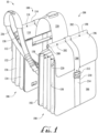
- a convertible briefcase and garment case with adjustable saddlebag attachment apparatus (“apparatus") 10 is shown.
- the apparatus 10 is generally configured such that a first container portion 100 is configured as a briefcase and can function as one saddlebag, while a second container portion 184 is configured as a garment bag and can function as a complimentary saddlebag.
- the first container portion 100 and the second container portion 184 are connected by a shoulder harness 228 allowing them to be suspended on either side of a user's shoulder (not shown), or over the seat of a motorcycle (not shown) or similar carrying mode.
- first container portion 100 and the second container portion 184 can be attached directly to each other (i.e., omitting first rear cover 108, second rear cover 192), and alternatively can be used independently of each other, and when used independently, either may be worn in the manner of an over-the-shoulder bag or as a conventional backpack by virtue of a shoulder strap 236 that can be connected to the first container portion 100 and the second container portion 184 in a variety of configurations.
- the first container portion 100 Configured as an expandable briefcase, the first container portion 100 includes a first front side 102 and a first back side 104 ( FIG. 4 ) separated by an expandable first pleated section 106, and a first bottom side (not shown).
- the first front side 102 and first pleated section 106 are connected by a zipper closure (see FIG. 8 ) that allows the first front side 102 to be opened or partially opened, making it easier to access the interior.
- a first rear cover 108 FIGS. 5A, 5B
- the first rear cover 108 is used when the first container 100 is carried either by itself, or when the apparatus 10 is configured as saddlebags, or at any time when the first back side 104 would otherwise be visible or exposed.
- the first container portion 100 includes a first overlapping portion 110 comprising a first flap 112.
- the first overlapping portion 110 is configured for securing items stored inside the first container portion 100.
- the first overlapping portion 110 also comprises a first handle support 114 preferably disposed lengthwise along its apex.
- the first handle support 114 encloses a preferably substantially rigid first dowel 116 that imparts strength and resiliency to the first overlapping portion 110.
- Two first handle anchor holes 118 are formed below the first handle support 114 and accommodate a pair of first removable o-rings 120 that engage a removable first handle 122, which is preferably padded for user comfort.
- a first decorative strap 124 extends over the first overlapping portion 110, including the first flap 112, from the first back side 104 to the first front side 102, and is preferably centered on the first container portion 100.
- the first decorative strap 124 includes a first tongue 126 that overhangs the first flap 112, and engages a first lock 128 located on the first front side 102.
- Below the first lock 128, an extension of the first decorative strap 124 includes a first pocket 130 for accommodating excess of the first tongue 126 when it engages the first lock 128.
- the first decorative strap 124 also serves to secure the first overlapping portion 110 to the first front side 102.
- the first lock 128 may be a traditional buckle, keyed lock, combination lock, or any other locking feature suitable for securing the first decorative strap 124.
- the first pocket 130 helps prevent the first tongue 126 of the first decorative strap 124 from curling away from the first front side 102 when locked in position.
- the first pleated section 106 includes a rear pleat 132 adjacent the first back side 104, a front pleat 134 adjacent the first front side 102, with a center pleat 136 between them.
- a male portion guillotine connector 138 is preferably affixed near the top of the center pleat 136.
- the male portion guillotine connector 138 pairs with a female portion guillotine connecter 140 on a shoulder strap 236 ( FIG. 11 ) when the first container portion 100 is to be carried over a user's shoulder using another male portion guillotine connector 138 on the opposing side of the first pleated section 106.
- a guillotine-type connector is specified in the illustrated embodiment due to its ability to rotate, any connector allowing the first container portion 100 to rotate relative to the shoulder strap 236, while remaining securely affixed thereto is contemplated.
- the first container portion 100 is shown with the first overlapping portion 110 opened, to reveal various internal components.
- the first container portion100 includes briefcase features and includes a keychain holder 142, a wallet section 144 for credit or similar card storage, and a pen storage 146 for holding pens, stylus, or other similar implements. These features are preferably located in a first compartment 148 corresponding with the front pleat 134.
- the first container portion 100 also comprises one or more electronics pockets 150 for storing cell phones and similar personal electronics.
- the first container portion 100 also includes a dual pocket 152 that includes a first pocket for holding an electronic item, and a second pocket for holding an electronic item battery to wirelessly charge the electronic item.
- the electronics pockets 150 and the dual pocket 152 are preferably located in a third compartment 154.
- the third compartment 154 is sized to accommodate preferable miscellaneous items such as a phone, charger, etc.
- a second compartment 156 between the first compartment 148 and the third compartment 154 is sized to accommodate a laptop computer, similar electronics device, or documents.
- the first compartment 148, second compartment 156 and third compartment 154 , or any combination thereof may have foam backing or be otherwise padded to ensure the safety of electronics and other items in the first container portion 100.
- additional features of the first overlapping portion 110 include embedded magnetic closures 158 on the first flap 112 corresponding to complimentary embedded magnetic closures 158 on the first front side 102.
- the embedded magnetic closures 158 help to ensure the first flap 112 does not curl up at the edges when the first overlapping portion is secured using the first lock 128.
- a pair of umbrella straps 160 may be included for securing an umbrella or newspaper (not shown).
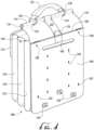
- FIG. 4 a rear view of the first container portion 100 is shown, including the first back side 104 with the first rear cover 108 ( FIGS. 5A, 5B ) removed or prior to installation.
- the first back side 104 includes two top female portion guillotine fasteners 140 for accommodating the first rear cover 108, with releases accessible atop the first back side104.
- Two rear panel keyhole portions 162 of pin and keyhole or similar fasteners are included below the female portion guillotine connectors 140 for securing the first rear cover 108 over the first back side 104.
- the first back side 104 also includes a series of harness keyhole portions 164 of pin and keyhole or similar fasteners arranged in parallel rows, thus enabling the shoulder harness 228 ( FIGS. 10A and 10B ) to be installed at a variety of heights on the first back side 104 according to preference.
- a series of three additional male portion guillotine connectors 138 are located near the bottom of the first back side 104 to accommodate complimentary female portion guillotine fasteners 140 on a shoulder strap 236 ( FIG. 11 ).
- the male portion guillotine connectors 138 on the first back side 104 are preferably raised to account for the thickness of the first rear cover 108.
- two male portion guillotine connectors 138 are located on the first bottom side (not shown) adjacent the first back side 104, and one male portion guillotine connector 138 is present adjacent the bottom of the first back side 104 either in the middle, or to the right or the left of the first back side 104.
- a first upper slot 166 is disposed above a preferably larger first lower slot 168.
- the first upper slot 166 and first lower slot 168 are preferably substantially the same width, corresponding to the width of the shoulder harness 228, allowing the shoulder harness 228 to slide into the first upper slot 166, and out through the first lower slot 168 where it engages the harness keyhole portions 164 of the pin and keyhole fasteners prior to installation of the first rear cover 108.
- a strap loop 170 designed to accommodate the shoulder strap 236 for configuring the first container portion 100 as a backpack or shoulder bag according to preference.
- FIGS. 5A and 5B the front and rear, respectively, of the preferred embodiment of the first rear cover 108 is shown.
- the front ( FIG. 5A ) of the first rear cover 108 includes a portion of the first decorative strap 124 that conveys the appearance of it extending completely over the first container portion 100.
- three first sliding doors 178 are provided for opening three first shoulder strap ports 180 ( FIG. 5B ) in order to access the male portion guillotine connectors 138 on the first back side 104 of the first container portion 100 when the first rear cover 108 is affixed thereto.
- only one first shoulder strap port 180 is present, and in a position to access the one male portion guillotine connector 138 on the first back side 104 of the alternate embodiment of the first container 100.
- At the top of the first rear cover 108 other male portion guillotine connectors 138 corresponding to the female portion guillotine connectors 140 of the first rear cover 108 are provided.
- rear panel pin portions 176 corresponding to the rear panel keyhole portions 162 ( FIG.
- a harness cutout 182 is provided for accommodating the shoulder harness 228.
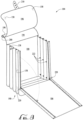
- the second container portion 184 is shown.
- the second container portion 184 is designed to match the first container portion 100, providing a matching appearance when the first container portion 100 and the second container portion 184 are connected together or joined by the shoulder harness 228.
- the second container portion 184 includes a second front side 186, a second back side 188, with a second pleated section 190 between them, and a second bottom side (not shown).
- the second container portion 184 has a second rear cover 192, substantially similar to the first rear cover 108, removably covering the second back side 188.
- a second overlapping portion 194 with a second flap 196 covers the second container portion 184.
- the second overlapping portion 194 includes a second handle support 198 preferably enclosing a second dowel 200.
- Second handle anchor holes 202 accommodate second removable o-rings 204 that attach a removable second handle 206 to the second container portion 184.
- the second container portion 184 includes a second decorative strap 208 that extends over the second overlapping portion 194, including the second flap 196, from the second back side 188 to the second front side 186, and is preferably centered on the second container portion 184.
- the second decorative strap 208 includes a second tongue 210 that overhangs the second flap 196, and engages a second lock 212 located on the second front side 186.
- an extension of the second decorative strap 208 includes a second pocket 214 for accommodating excess of the second tongue 210 when it engages the second lock 212.
- the second decorative strap 208 also serves to secure the second overlapping portion 194 to the second front side 186.
- the second lock 212 may be a traditional buckle, keyed lock, combination lock, or any other locking feature suitable for securing the second decorative strap 208.
- the second pocket 214 helps prevent the second tongue 210 from curling away from the second front side 186 when locked in position.
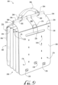
- the second container portion 184 also preferably includes a strap loop 170 ( FIG. 9 ) similar in size and placement to the strap loop 170 of the first container portion 100.
- the second pleated section 190 of the second container portion 184 is preferably slightly larger than the first pleated section 106 due, in part, to the configuration of the second container 184 as an overnight bag or similar overnight case.
- the first pleated section 106 has only three gussets corresponding, to the first compartment 148, second compartment 156 and third compartment 154.
- the second pleated section 190 has four gussets.
- the second pleated section 190 includes one or more magnetic closures 158 to close one of the gussets.
- the gussets of the second pleated section 190 are preferably all of equal size.
- the second container portion preferably has male portion guillotine connectors 138 on either side of the second pleated section 190.
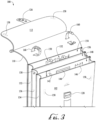
- the second container 184 is shown with the second decorative strap 208 unlocked and the second overlapping portion 194 lifted up.
- Extending between each of the gussets of the second pleated section 190 is a removable divider 218, one or more of which may be removed depending on the space needs of a user when packing. For example, a user traveling with very few clothes may close the magnetic closures 158 of the second pleated section 190 to reduce the size of the second container portion 184. Alternatively, a user traveling with many different clothing items, or bulky items, may remove one or more of the removable dividers 218 (and, according to preference, leave the magnetic closures 158 open) to accommodate the larger items.
- the second container 184 also preferably includes a zipper closure 220 which allows the second front side 186 to be opened or partially opened, making it easier to access the interior.
- the second front side 186 and the second flap 196 of the second overlapping portion 194 of the second container portion 184 preferably include magnetic closures 158 for securing the second flap 196 when the second overlapping portion 194 is closed and the second decorative strap 208 is fastened using the second lock 212.
- the second container 184 is shown in an open configuration with the second overlapping portion 194 opened, all removable dividers 218 ( FIG. 7 ) removed, and with the zipper closures 220 opened and second front side 186 folded down to allow easy access to the interior of the second container portion 188 for packing.
- the removable dividers 218 and the second front side 186 are substantially resilient, stiff panels, allowing them to resist pressure from clothing or other items (not shown) contained in the second container portion 184.
- each of the gussets of the second pleated section 190 may comprise clasps 222 that serve as guides for the removable dividers 218 ensuring their proper fit in the second container portion 184.
- the second back side 188 is shown.
- the second back side 188 is somewhat similar to the first back side 104, although it includes male portion guillotine connectors 138 (instead of female portion guillotine connectors 140) near the top, and pin portions 176 (as opposed to rear panel keyhole portions 162) near the bottom, which allows the second back side 188 to be affixed to the first back side 104, and thus, allows the second container portion 184 to be affixed directly to the first container portion 100.
- the second back side 188 includes a second upper slot 224 and a preferably larger second lower slot 226, in the same position as the first upper slot 166 and first lower slot 168.
- harness keyhole portions 164 formed in substantially the same position so as to mirror the harness keyhole portions 164 of the first back side 104, enabling users to install the shoulder harness 228 in substantially the same position on the first container portion 100 relative to the second container portion 184 for symmetry.
- the second back side 188 of the preferred embodiment of the second container 184 also includes three male portion guillotine connectors 138, proximate to the male portion guillotine connectors 138 of the first back side 104 ( FIG. 4 ).
- two male portion guillotine connectors 138 are located on the second bottom side (not shown) adjacent the second back side 188, and one male portion guillotine connector 138 is present adjacent the bottom of the second back side 188 either in the middle, or to the right or the left of the second back side 188 .
- the placement of the male portion guillotine connectors 138 of the preferred embodiments enables the second container portion 184 to be worn over the shoulder, and the placement of the male portion guillotine connectors 138 enables the second container 184 to be worn as a backpack in a manner similar to the first container portion 100 (see FIG. 13 ). Also shown in this view is the strap loop 170 located on the second decorative strap 208, used when the second container 184 is worn as a backpack.
- the preferred and alternate embodiment of the second rear cover (not shown) is provided for covering the second back side 188 and is virtually identical in appearance to the first rear cover 108, and includes all of the features of the first rear cover 108 (except it has female portion guillotine connectors 140 and rear panel keyhole portions 162 of the pin and keyhole connectors).
- the shoulder harness 228 is shown by itself and in the process of installation, respectively.
- the shoulder harness 228 is preferably an elongated rectangular piece, with a shoulder harness handle 230 preferably located at its midsection.
- the shoulder harness 228 is also preferably backed with foam or a similar cushioning material allowing a user to comfortably wear the shoulder harness 228 with the first container portion 100 and the second container portion 184 attached thereto.
- the shoulder harness handle 230 is preferably defined by two cutout portions 232 on either side, and is preferably curved upward to foster a firm grip by the user.
- the pin portions 176 of the pin and keyhole fasteners are located at either end of the shoulder harness 228, the pin portions 176 of the pin and keyhole fasteners are located.
- two pair of pin portions 176 are provided for affixing to a row of harness keyhole portions 164 on the first back side 104 and a row of harness keyhole portions 164 on the second back side 188.
- Extending from either end of the shoulder harness 228 are flat loops 234 that allow the shoulder harness 228 to be anchored to other structures, for example when attached to a motorcycle as a saddlebag.
- the shoulder harness 228 is shown being installed on the first container portion 100.
- the shoulder harness 228 is inserted into the first upper slot 166 so that it comes out of the first lower slot 168.
- the shoulder harness 228 can be pulled out of the first lower slot 168 sufficiently to anchor the pin portions 176 in the harness keyhole portions 164 at a preferred height on the first back side 104.
- the shoulder harness 228 is installed on the second container portion 184 in the same manner, and preferably on corresponding harness keyhole portions 164 for a balanced appearance, although other configurations are possible according to preference. With the shoulder harness 228 attached to the first container portion 100 and the second container portion 184, both can be carried with ease using the shoulder harness 228 over a user's shoulder, and can be picked up from a standing location using the shoulder harness handle 230.
- a shoulder strap 236 may be employed.
- the shoulder strap 236 is preferably comprised of a first main strap portion 238 and a second main strap portion 240, connected by a removable o-ring 242.
- the first main strap portion 238 and the second main strap portion 240 are comprised of shoulder strap holes 174 in varying positions along the length of each portion.
- a first strap extension 244 extends from the first main strap portion 238 and a second strap extension 246 extends from the second main strap portion 240.
- the first strap extension 244 and second strap extension 246 are preferably fitted with shoulder strap adjustment hardware 172 comprised of shoulder strap extension pins 216.
- the shoulder strap extension pins 216 have a preferable flat end, and connect with the first main strap portion 238 and second main strap portion 240 by inserting the shoulder strap extension pins 216 into the shoulder strap holes 174 to allow the shoulder strap 236 to be easily shortened or lengthened while still connected to either the first container portion 100 or the second container portion 184.
- the first strap extension 244 and the second strap extension 246 are preferably fitted with female portion guillotine connectors 140 and are thus connectable to the male portion guillotine connectors 138 on the first pleated side 106, second pleated side 190, first back side 104 and second back side 188.
- an accompanying part of the shoulder strap 236 is a shoulder strap sleeve 248, comprising a first sleeve portion 250 and a second sleeve portion 252 connected by a shoulder sleeve fastener 254.
- the first sleeve portion 250 and the second sleeve portion 252 preferably cover the removable o-ring 242, thus shielding a user's shoulder from contact with it.
- the shoulder sleeve fastener 254 allows the first sleeve portion 250 and the second sleeve portion 252 to be separated, thus allowing the removable strap o-ring 242 to connect to the strap loop 170 on either the first container portion 100 or the second container portion 184.
- the shoulder strap sleeve 248 is sufficiently padded, such that it is comfortable when worn, even supporting the weight of the first container portion 100 or the second container portion 184.
- a handle extension 256 may be provided for carrying the first container portion 100 and the second container portion 184, in either a connected or disconnected arrangement, without using the shoulder harness 228, or the shoulder strap 236.
- the handle extension 256 includes a handle portion 258 connected to a first connecting portion 260 and a second connecting portion 262.
- the first connecting portion 260 and the second connecting portion 262 span the distance between the first handle 122 and the second handle 206, connecting thereto by means of a first forward connecting loop 264 and a first rear connecting loop 266, each affixed the first handle 122 on the first container 100, and a second forward connecting loop 268 and a second rear connecting loop 270, each affixed to the second handle 206.
- first forward connecting loop 264, first rear connecting loop 266, second forward connecting loop 268, and second rear connecting loop 270 are affixed using a connecting loop strap 272 and stud 274 arrangement whereby each connecting loop strap 272 is looped around the first handle 122 (or, alternatively, the second handle 206), and is passed through a retaining loop 276 which helps confine the connecting loop strap 272 on each stud 274.
- the male guillotine connectors 138 of the first back side 104 are staggered in relation to the male guillotine connectors 138 of the second back side 188 ( FIG. 9 ), thereby preventing contact and enabling the first container 100 and second container 184 to remain in close proximity when in a connected arrangement.
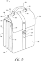
- the first container 100 is shown in a backpack configuration.
- the first rear cover 108 is attached to the first back side 104 and the shoulder strap 236 is connected to the first container 100, looping the removable o-ring 242 into the strap loop 170.
- the first strap extension 244 is connected to the first back side 104 by opening the first sliding door 178 of the first rear cover 108 and inserting the male portion guillotine connector 138 of the first back side 104 into the female portion guillotine connector 140 of the first strap extension 244.
- the apparatus 10 can be assembled in a variety of orientations, depending on the user preference. For purposes of discussion each assembly is described as though the apparatus 10 is assembled from a fully disassembled configuration.
- the primary configuration of the apparatus 10 is for use as a saddlebag or over-the-shoulder bag, in which both the first container portion 100 and the second container portion 184 are in use.
- a user obtains the first container portion 100, disengages the first lock 128, and opens the first flap 112 to expose the first compartment 148, second compartment 156, and third compartment 154.
- the user may connect the user's keys (not shown) to the keychain holder 142, insert one or more credit cards or credit card-shaped cards into the wallet section 144, and insert one or more pens, pencils or stylus in the pen storage 146.
- the user may place a cell phone (not shown) into the electronics pocket 150, and optionally may place an extra cell phone battery (not shown) in the dual pocket 152.
- Papers and other documents may be inserted in the third compartment 156, and optionally, in the first compartment 148 and second compartment 154 to the extent there is room to accommodate them.
- the rear pleat 132, front pleat 134 and center pleat 136 may expand as necessary depending on the volume of objects stored in the first container portion 100.
- a user may insert a folded umbrella or newspaper (not shown) through the umbrella straps 160 to be held securely therein.
- the first flap 112 is closed over the top of the first container portion and the first decorative strap 124 anchored to the first lock 128, the magnetic closures 158 on the first flap 112 will hold it against the first front side 102 to prevent the sides of the first flap 112 from curling up.
- the user then installs clothing or similar items into the second container portion 184.
- the second container portion 184 opens in a manner similar to the first container portion 100, except that once the second decorative strap 208 has been released from the second lock 212, and the second flap 196 folded back, the zipper closure 220 may be opened, allowing the second front side 186 to fold down and permit easier access to the interior of the second container portion 184. With the second container portion 184 opened, a user may install or remove one or more of the removable dividers 218 for effectively separating different types of clothing items (not shown). If a large quantity of clothing items are stored in the second container portion 184, the second pleated section will expand to accommodate them.
- the second pleated section 190 can be reduced in size by bringing the magnetic closures 158 in the pleated section 190 together.
- the zipper closure 220 can be closed, and the second flap 196 folded back over the top of the second container portion 184. Similar to the first container portion 100, the second tongue 210 is secured using the second lock, and the magnetic closures 158 on the second flap 196 and the second front side 186 couple together.
- the apparatus 10 can be assembled for transport.
- the shoulder harness 228 is attached to the first back side 104 and the second back side 188 by inserting the pin portions of the shoulder harness 228 into the harness keyhole portions 164 of the first back side 104 and the second back side 188.
- Preferably placement of the pin portions 176 will be on the same row of harness keyhole portions 164 for even distribution of the weight of the apparatus 10.
- the shoulder harness 228 extends through the first upper slot 166 and first lower slot 168 on the first container portion 100 and extends through the second upper slot 224 and the second lower slot 226 on the second container portion 184.
- the upper slots 166/224 and the lower slots 168/226 help anchor the shoulder harness 228 near the top of the first container 100 and the second container 184, respectively.
- the first rear cover 108 is installed over the first back side 104 and the second rear cover 192 is installed over the second back side 188. This is accomplished by inserting the pin portions 176 located on the first rear cover 192 into the rear panel keyhole portions 162 located on the first back side 104 and anchoring the male portion guillotine connectors on the first back side 104 into the female portion guillotine connectors 140 of the first rear cover 108.
- the apparatus can be worn on a user's shoulder or installed similar to a set of saddlebags on a motorcycle or other similar location.
- the shoulder strap 236 is preferably also employed to prevent the apparatus 10 from slipping.
- the shoulder strap 236 preferably anchors to the center male portion guillotine connector 138 on the first back side 104 and the second back side 188, and are accessed through the middle sliding doors 178 of the first rear cover 108 and the second rear cover 192.
- the apparatus 10 may also be reconfigured in several different ways for alternative uses. As discussed by omitting the first rear cover 108 and the second rear cover 192, the first container portion 100 can be connected directly to the second container portion 184 to function as one large apparatus 10. Alternatively, the first container portion 100 or the second container portion 184 may be worn either over the shoulder or as a backpack.
- the shoulder strap 236 is attached to a male portion guillotine connector on either the first pleated section 106 or the second pleated section 190, and also attached to one of the side male portion guillotine connectors 138 on the first back side 104 or second back side 188, as discussed above, through the sliding doors 178 of the first rear cover 108 or second rear cover 192.
- the second strap extension 246 is connected to the first back side 104 by opening the opposite first sliding door 178 of the first rear cover 108 and inserting the male portion guillotine connector 138 of the first back side 104 into the female portion guillotine connector 140 of the second strap extension 246.
- the first strap extension 244 is connected to the first back side 104 by inserting the male portion guillotine connector 138 of the first bottom side (not shown) adjacent the first back side 104 into the female portion guillotine connector 140 of the first strap extension 244.
- the second strap extension 246 is connected to the first bottom side (not shown) inserting the male portion guillotine connector 138 of the first bottom side (not shown) adjacent the first back side 104 into the female portion guillotine connector 140 of the second strap extension 246.
- the shoulder strap 236 adjusts to a user's desired length by inserting the shoulder strap extension pins 216 into the selected shoulder strap holes 174.
- the shoulder strap sleeve 248 may be disconnected into the first sleeve portion 250 and the second sleeve portion 252 to provide padding for a user's shoulders.
- the second container portion 184 and second back side 188 are substantially similar to the first container portion 100 and first back side 104, and likewise converts into a backpack configuration by attaching the second rear cover 192 to the second back side 188, connecting the removable o-ring 242 of the shoulder strap 236 to the strap loop 170, and connecting the first strap extension 244 and second strap extension 246 to male portion guillotine connectors 138.
- first container portion 100 and the second container portion 184 may also be used separately without either the shoulder harness 228 or the shoulder strap 236, in which case they may be simply carried by the first handle 122 or the second handle 206 according to preference.
- the embodiments disclosed may be made in various shapes, sizes, and materials.
- the soft-shell design shown and described could be constructed in hard-shell form made from various other materials including metals, and either design may have features such as being puncture or bullet proof, magnetically-attachable parts, a weapons compartment, leak proof and able to float, etc. Further, either design could include electronics such as satellite communications and GPS capability, built-in computer or other wireless devices, batteries, inductive or solar charging, and the like.
Landscapes
- Engineering & Computer Science (AREA)
- Mechanical Engineering (AREA)
- Portable Outdoor Equipment (AREA)
- Purses, Travelling Bags, Baskets, Or Suitcases (AREA)
Claims (5)
- Gepäcksystem zum Tragen von Gegenständen, wobei das Gepäcksystem Folgendes umfasst:eine Aktentasche (100), eine Kleidertasche (184), einen Satteltaschenriemen (228) und einen Einzeltaschentragriemen (236), wobei die Aktentasche (100) und die Kleidertasche (184) jeweils eine Bodenseite und eine Rückseite (104, 188) aufweisen, wobei die Rückseiten mehrere Satteltaschenbefestigungen entlang der Rückseiten aufweisen, die am Satteltaschenriemen (228) angebracht werden können, wobei die Rückseiten ferner mindestens eine erste Tragriemenbefestigung (138, 140) und mindestens eine zweite Tragriemenbefestigung (138) aufweisen, die ebenfalls an den Rückseiten oder an den Bodenseiten vorgesehen sind und am Einzeltaschentragriemen (236) angebracht werden können;wobei die Rückseiten ferner eine längliche Öffnung (168, 226) neben einem oberen Ende der Rückseiten aufweisen, die maßlich mit dem Satteltaschenriemen kompatibel ist, wobei der Satteltaschenriemen durch die Öffnungen passieren kann und sich zwischen der Aktentasche und der Kleidertasche erstreckt;wobei die Aktentasche und die Kleidertasche ferner parallele Seiten (106, 190) aufweisen, die eine Breite definieren, und wobei der Einzeltaschentragriemen an den parallelen Seiten angebracht werden kann, so dass die Aktentasche und die Kleidertasche getrennt getragen werden können; undwobei der Einzeltaschentragriemen ein erstes Ende (244, 238), ein zweites Ende (246, 240) und einen mittleren Abschnitt (242) aufweist, wobei der mittlere Abschnitt ein Beschlagteil (242) umfasst, das an der Aktentasche und der Kleidertasche angebracht werden kann, und wobei das erste Ende und das zweite Ende an den Tragriemenbefestigungen der Aktentasche und der Kleidertasche angebracht werden können, so dass die Aktentasche und die Kleidertasche getrennt als Rucksack getragen werden können.
- Gepäcksystem nach Anspruch 1, wobei das Anbringen des Satteltaschenriemens an den Satteltaschenbefestigungen entlang einer Länge der Rückseiten einstellbar ist, um einen Abstand zwischen der Aktentasche und der Kleidertasche einzustellen, wenn die Aktentasche und die Kleidertasche am Satteltaschenriemen angebracht sind.
- Gepäcksystem nach Anspruch 1, wobei die Aktentasche und die Kleidertasche ferner eine Bodenseite mit einer oder mehreren Tragriemenbefestigungen aufweisen.
- Gepäcksystem nach Anspruch 3, wobei das erste Ende und das zweite Ende des Einzeltaschentragriemens an den Tragriemenbefestigungen an der Bodenseite der Aktentasche und der Kleidertasche angebracht werden können, so dass die Aktentasche und die Kleidertasche getrennt als Rucksack getragen werden können.
- Gepäcksystem nach Anspruch 1, wobei die Rückseiten ferner ein Paar Abdeckungsbefestigungen aufweisen, die an einer Abdeckung angebracht werden können, wobei die Abdeckung die Satteltaschenbefestigungen, die Tragriemenbefestigungen und die Abdeckungsbefestigungen verdeckt.
Applications Claiming Priority (2)
| Application Number | Priority Date | Filing Date | Title |
|---|---|---|---|
| US201862638812P | 2018-03-05 | 2018-03-05 | |
| PCT/US2019/020835 WO2019173400A1 (en) | 2018-03-05 | 2019-03-05 | Convertible briefcase and garment case with adjustable saddlebag attachment |
Publications (4)
| Publication Number | Publication Date |
|---|---|
| EP3762281A1 EP3762281A1 (de) | 2021-01-13 |
| EP3762281A4 EP3762281A4 (de) | 2021-12-08 |
| EP3762281B1 true EP3762281B1 (de) | 2023-10-25 |
| EP3762281C0 EP3762281C0 (de) | 2023-10-25 |
Family
ID=67768288
Family Applications (1)
| Application Number | Title | Priority Date | Filing Date |
|---|---|---|---|
| EP19763221.9A Active EP3762281B1 (de) | 2018-03-05 | 2019-03-05 | Umwandelbare aktentasche und kleidungshülle mit einstellbarer satteltaschenbefestigung |
Country Status (3)
| Country | Link |
|---|---|
| US (1) | US10602833B2 (de) |
| EP (1) | EP3762281B1 (de) |
| WO (1) | WO2019173400A1 (de) |
Families Citing this family (11)
| Publication number | Priority date | Publication date | Assignee | Title |
|---|---|---|---|---|
| DE102016206842A1 (de) * | 2016-04-22 | 2017-10-26 | Bayerische Motoren Werke Aktiengesellschaft | Karosserieverkleidung für ein Kraftfahrzeug sowie Kraftfahrzeug mit Karosserieverkleidung |
| DK3592173T3 (da) | 2017-03-08 | 2024-09-23 | Yeti Coolers Llc | Beholder med magnetisk lukning |
| US10954055B2 (en) | 2017-03-08 | 2021-03-23 | Yeti Coolers, Llc | Container with magnetic closure |
| US11191346B2 (en) * | 2019-12-02 | 2021-12-07 | Paul Batushansky | Method and apparatus for deterring unauthorized mounting of a motorcycle |
| US11649089B2 (en) * | 2020-07-01 | 2023-05-16 | Sondra Calhoun | Collapsible snack caddy |
| US12035790B2 (en) * | 2021-07-07 | 2024-07-16 | Wilma Speelman | Travel accessory |
| US11992104B2 (en) | 2022-02-16 | 2024-05-28 | Yeti Coolers, Llc | Container with resealable closure |
| US12396545B2 (en) * | 2022-04-08 | 2025-08-26 | Tune Belt, Inc. | Running belt |
| US20230363517A1 (en) * | 2022-05-10 | 2023-11-16 | Ariane Pick | Twinpick Shoulder Bag |
| DE102022128436A1 (de) | 2022-10-27 | 2024-05-02 | ADVENATE GmbH | Satteltasche |
| TWI863402B (zh) * | 2023-07-03 | 2024-11-21 | 極點股份有限公司 | 具有固定繩之行李架 |
Family Cites Families (38)
| Publication number | Priority date | Publication date | Assignee | Title |
|---|---|---|---|---|
| US501821A (en) * | 1893-07-18 | Saddle-bags | ||
| CH237539A (de) | 1943-12-21 | 1945-04-30 | L Thaler | Am Gepäckträger von Fahrrädern anzuschnallende Einrichtung zum Mitführen von Gegenständen. |
| US3786972A (en) * | 1971-12-27 | 1974-01-22 | H Alley | Combination pannier bag, valise and back pack |
| US3830348A (en) * | 1972-10-13 | 1974-08-20 | M Ohyama | Collapsible luggage |
| US3937374A (en) * | 1974-10-21 | 1976-02-10 | Hine-Snowbridge, Inc. | Pannier bag construction and method of attachment |
| JPS51116210U (de) * | 1975-03-12 | 1976-09-21 | ||
| US4580706A (en) * | 1977-02-14 | 1986-04-08 | Jackson W S | Saddlebag and associated mounting arrangement for cycles |
| US4662548A (en) * | 1977-02-14 | 1987-05-05 | Eclipse, Inc. | Pannier and mounting arrangement for cycles |
| US4081061A (en) * | 1977-02-22 | 1978-03-28 | Harrison Leather Goods Corporation | Modular luggage |
| US4390088A (en) * | 1979-03-05 | 1983-06-28 | Brenner Richard K | Container bag system for bicycles |
| US4258869A (en) * | 1979-04-30 | 1981-03-31 | Hilgendorff Wayne P | Saddle pack |
| US4442960A (en) | 1981-10-22 | 1984-04-17 | Bagman, Inc. | Saddlebags |
| US4420068A (en) * | 1981-12-07 | 1983-12-13 | Kingport, Ltd. | Combination carrying case and detachable garment carrier |
| US4402439A (en) * | 1981-12-23 | 1983-09-06 | Brown Glen J | Bicycle saddle bags |
| US4491258A (en) * | 1982-05-03 | 1985-01-01 | Jones Richard R | Convertible backpack |
| US4609084A (en) * | 1982-09-29 | 1986-09-02 | Thomas Frank O | Travel pack |
| JPS60249906A (ja) * | 1984-05-25 | 1985-12-10 | 本田技研工業株式会社 | バツグ |
| US4577786A (en) * | 1984-07-13 | 1986-03-25 | Hine-Snowbridge, Inc. | Pannier bag having a clamping device with locking member |
| IT215593Z2 (it) * | 1989-02-13 | 1990-10-12 | Lee Expeditions Limited | Bisaccia da viaggio. |
| US5129560A (en) * | 1989-09-15 | 1992-07-14 | Stephanie Herman | Utility bag system |
| US5062717A (en) * | 1990-10-31 | 1991-11-05 | Dru Shockley | Shopping bag with handle |
| US5186290A (en) * | 1992-01-30 | 1993-02-16 | Hiromitsu Takayama | Combination trunk |
| US5544792A (en) * | 1994-09-06 | 1996-08-13 | Arnwine; Billy C. | Convertible student book bag |
| US5603441A (en) * | 1994-10-24 | 1997-02-18 | Easter; Michael D. | Multi-purpose front/back pack apparatus |
| US5586703A (en) * | 1995-05-26 | 1996-12-24 | Radar; Elizabeth | Dual field pack |
| US5630536A (en) * | 1995-08-25 | 1997-05-20 | Bugnaski; Mark S. | Adjustable body pack |
| US5947241A (en) * | 1997-05-27 | 1999-09-07 | Rubbermaid Incorporated | Joinable, soft-sided containers |
| US5890639A (en) * | 1998-02-13 | 1999-04-06 | Hancock; Dennis | Multi-purpose bag system |
| US6523653B2 (en) | 2001-01-19 | 2003-02-25 | Roegner Deanna | Portable removable carrying case organizer |
| US7757911B2 (en) * | 2004-03-01 | 2010-07-20 | Robert Marshall Barker | Convertible pack |
| US7568600B2 (en) * | 2006-01-19 | 2009-08-04 | Travel Caddy, Inc. | Tank bag with integral cord adjustment system |
| US7600620B2 (en) * | 2006-07-14 | 2009-10-13 | Hammond Richard P | Apparatus and method for enabling a briefcase to carry a supplemental bag |
| US8152037B2 (en) * | 2008-05-07 | 2012-04-10 | The Stanley Works Israel Ltd. | Tool carrier |
| US20100147918A1 (en) | 2008-12-12 | 2010-06-17 | Hensley Patrick L | Bag |
| US20140048575A1 (en) | 2012-08-14 | 2014-02-20 | Shelley Doris Kennedy-Sharpe | Split compartment system |
| US8844717B1 (en) * | 2012-10-24 | 2014-09-30 | Stacy R. Ross | Collapsible upright tool caddy system |
| US10029842B2 (en) * | 2014-02-07 | 2018-07-24 | Yeti Coolers, Llc | Insulating device |
| US9440696B2 (en) * | 2014-02-12 | 2016-09-13 | Portage World-Wide, Inc. | Adjustabable bag harness for a bicycle |
-
2019
- 2019-03-05 EP EP19763221.9A patent/EP3762281B1/de active Active
- 2019-03-05 WO PCT/US2019/020835 patent/WO2019173400A1/en not_active Ceased
- 2019-03-05 US US16/293,579 patent/US10602833B2/en active Active
Also Published As
| Publication number | Publication date |
|---|---|
| EP3762281A1 (de) | 2021-01-13 |
| US10602833B2 (en) | 2020-03-31 |
| US20190269230A1 (en) | 2019-09-05 |
| EP3762281C0 (de) | 2023-10-25 |
| EP3762281A4 (de) | 2021-12-08 |
| WO2019173400A1 (en) | 2019-09-12 |
Similar Documents
| Publication | Publication Date | Title |
|---|---|---|
| EP3762281B1 (de) | Umwandelbare aktentasche und kleidungshülle mit einstellbarer satteltaschenbefestigung | |
| US5318084A (en) | Shoulder strap with integral pockets | |
| US9320341B2 (en) | Interior cradle for a portable electronic device | |
| US6305587B1 (en) | Expandable computer tote | |
| US11607029B2 (en) | Luggage systems | |
| US6681936B2 (en) | Cosmetic and utility kit | |
| US7040486B2 (en) | Cosmetic and utility kit | |
| US8157140B2 (en) | Wearable zip wallet | |
| US9480315B2 (en) | Convertible purse with interchangeable covers | |
| US5887770A (en) | Convertible waist pack, day backpack and shoulder bag | |
| EP3740097B1 (de) | Reisezubehör und verfahren | |
| US9943149B2 (en) | Carrying cases | |
| US20240074556A1 (en) | Luggage systems | |
| US11202490B1 (en) | Smart bag | |
| US20190387866A1 (en) | Backpack | |
| US7370781B2 (en) | Versatile cellular telephone holder | |
| US20240426570A1 (en) | Utility Fanny Pack System | |
| US20190307215A1 (en) | Rolling convertible luggage | |
| US12150539B1 (en) | Single-bag pack for everyday carry and for travel | |
| US20130186924A1 (en) | Passenger-Accessible, Flexible Portable Motorcycle Organizer Pouch | |
| US20250098842A1 (en) | Professional briefcase / tote bag with hidable handles and backpack straps | |
| US20080264986A1 (en) | Modular article carrying system | |
| JP3057143U (ja) | 背負いバッグ | |
| JP3057142U (ja) | 背負いバッグ付随用小物収納体 |
Legal Events
| Date | Code | Title | Description |
|---|---|---|---|
| STAA | Information on the status of an ep patent application or granted ep patent |
Free format text: STATUS: THE INTERNATIONAL PUBLICATION HAS BEEN MADE |
|
| PUAI | Public reference made under article 153(3) epc to a published international application that has entered the european phase |
Free format text: ORIGINAL CODE: 0009012 |
|
| STAA | Information on the status of an ep patent application or granted ep patent |
Free format text: STATUS: REQUEST FOR EXAMINATION WAS MADE |
|
| 17P | Request for examination filed |
Effective date: 20200903 |
|
| AK | Designated contracting states |
Kind code of ref document: A1 Designated state(s): AL AT BE BG CH CY CZ DE DK EE ES FI FR GB GR HR HU IE IS IT LI LT LU LV MC MK MT NL NO PL PT RO RS SE SI SK SM TR |
|
| AX | Request for extension of the european patent |
Extension state: BA ME |
|
| DAV | Request for validation of the european patent (deleted) | ||
| DAX | Request for extension of the european patent (deleted) | ||
| A4 | Supplementary search report drawn up and despatched |
Effective date: 20211105 |
|
| RIC1 | Information provided on ipc code assigned before grant |
Ipc: A45F 3/04 20060101ALI20211101BHEP Ipc: A45F 3/02 20060101ALI20211101BHEP Ipc: A45C 3/00 20060101ALI20211101BHEP Ipc: A45C 13/30 20060101ALI20211101BHEP Ipc: B62J 9/00 20200101AFI20211101BHEP |
|
| RIC1 | Information provided on ipc code assigned before grant |
Ipc: B62J 9/27 20200101ALI20230222BHEP Ipc: B62J 9/26 20200101ALI20230222BHEP Ipc: A45F 4/02 20060101ALI20230222BHEP Ipc: A45F 3/04 20060101ALI20230222BHEP Ipc: A45F 3/02 20060101ALI20230222BHEP Ipc: A45C 3/00 20060101ALI20230222BHEP Ipc: A45C 13/30 20060101ALI20230222BHEP Ipc: A45C 13/02 20060101ALI20230222BHEP Ipc: A45C 7/00 20060101ALI20230222BHEP Ipc: A45C 3/02 20060101ALI20230222BHEP Ipc: B62J 9/00 20060101AFI20230222BHEP |
|
| GRAP | Despatch of communication of intention to grant a patent |
Free format text: ORIGINAL CODE: EPIDOSNIGR1 |
|
| STAA | Information on the status of an ep patent application or granted ep patent |
Free format text: STATUS: GRANT OF PATENT IS INTENDED |
|
| INTG | Intention to grant announced |
Effective date: 20230510 |
|
| GRAS | Grant fee paid |
Free format text: ORIGINAL CODE: EPIDOSNIGR3 |
|
| GRAA | (expected) grant |
Free format text: ORIGINAL CODE: 0009210 |
|
| STAA | Information on the status of an ep patent application or granted ep patent |
Free format text: STATUS: THE PATENT HAS BEEN GRANTED |
|
| AK | Designated contracting states |
Kind code of ref document: B1 Designated state(s): AL AT BE BG CH CY CZ DE DK EE ES FI FR GB GR HR HU IE IS IT LI LT LU LV MC MK MT NL NO PL PT RO RS SE SI SK SM TR |
|
| REG | Reference to a national code |
Ref country code: GB Ref legal event code: FG4D |
|
| REG | Reference to a national code |
Ref country code: CH Ref legal event code: EP |
|
| REG | Reference to a national code |
Ref country code: DE Ref legal event code: R096 Ref document number: 602019040109 Country of ref document: DE |
|
| REG | Reference to a national code |
Ref country code: IE Ref legal event code: FG4D |
|
| U01 | Request for unitary effect filed |
Effective date: 20231123 |
|
| U07 | Unitary effect registered |
Designated state(s): AT BE BG DE DK EE FI FR IT LT LU LV MT NL PT SE SI Effective date: 20231130 |
|
| U20 | Renewal fee for the european patent with unitary effect paid |
Year of fee payment: 6 Effective date: 20240207 |
|
| PG25 | Lapsed in a contracting state [announced via postgrant information from national office to epo] |
Ref country code: GR Free format text: LAPSE BECAUSE OF FAILURE TO SUBMIT A TRANSLATION OF THE DESCRIPTION OR TO PAY THE FEE WITHIN THE PRESCRIBED TIME-LIMIT Effective date: 20240126 |
|
| PG25 | Lapsed in a contracting state [announced via postgrant information from national office to epo] |
Ref country code: IS Free format text: LAPSE BECAUSE OF FAILURE TO SUBMIT A TRANSLATION OF THE DESCRIPTION OR TO PAY THE FEE WITHIN THE PRESCRIBED TIME-LIMIT Effective date: 20240225 |
|
| PG25 | Lapsed in a contracting state [announced via postgrant information from national office to epo] |
Ref country code: ES Free format text: LAPSE BECAUSE OF FAILURE TO SUBMIT A TRANSLATION OF THE DESCRIPTION OR TO PAY THE FEE WITHIN THE PRESCRIBED TIME-LIMIT Effective date: 20231025 |
|
| PG25 | Lapsed in a contracting state [announced via postgrant information from national office to epo] |
Ref country code: IS Free format text: LAPSE BECAUSE OF FAILURE TO SUBMIT A TRANSLATION OF THE DESCRIPTION OR TO PAY THE FEE WITHIN THE PRESCRIBED TIME-LIMIT Effective date: 20240225 Ref country code: GR Free format text: LAPSE BECAUSE OF FAILURE TO SUBMIT A TRANSLATION OF THE DESCRIPTION OR TO PAY THE FEE WITHIN THE PRESCRIBED TIME-LIMIT Effective date: 20240126 Ref country code: ES Free format text: LAPSE BECAUSE OF FAILURE TO SUBMIT A TRANSLATION OF THE DESCRIPTION OR TO PAY THE FEE WITHIN THE PRESCRIBED TIME-LIMIT Effective date: 20231025 |
|
| PG25 | Lapsed in a contracting state [announced via postgrant information from national office to epo] |
Ref country code: RS Free format text: LAPSE BECAUSE OF FAILURE TO SUBMIT A TRANSLATION OF THE DESCRIPTION OR TO PAY THE FEE WITHIN THE PRESCRIBED TIME-LIMIT Effective date: 20231025 Ref country code: PL Free format text: LAPSE BECAUSE OF FAILURE TO SUBMIT A TRANSLATION OF THE DESCRIPTION OR TO PAY THE FEE WITHIN THE PRESCRIBED TIME-LIMIT Effective date: 20231025 Ref country code: NO Free format text: LAPSE BECAUSE OF FAILURE TO SUBMIT A TRANSLATION OF THE DESCRIPTION OR TO PAY THE FEE WITHIN THE PRESCRIBED TIME-LIMIT Effective date: 20240125 Ref country code: HR Free format text: LAPSE BECAUSE OF FAILURE TO SUBMIT A TRANSLATION OF THE DESCRIPTION OR TO PAY THE FEE WITHIN THE PRESCRIBED TIME-LIMIT Effective date: 20231025 |
|
| PG25 | Lapsed in a contracting state [announced via postgrant information from national office to epo] |
Ref country code: CZ Free format text: LAPSE BECAUSE OF FAILURE TO SUBMIT A TRANSLATION OF THE DESCRIPTION OR TO PAY THE FEE WITHIN THE PRESCRIBED TIME-LIMIT Effective date: 20231025 |
|
| REG | Reference to a national code |
Ref country code: DE Ref legal event code: R097 Ref document number: 602019040109 Country of ref document: DE |
|
| PG25 | Lapsed in a contracting state [announced via postgrant information from national office to epo] |
Ref country code: SK Free format text: LAPSE BECAUSE OF FAILURE TO SUBMIT A TRANSLATION OF THE DESCRIPTION OR TO PAY THE FEE WITHIN THE PRESCRIBED TIME-LIMIT Effective date: 20231025 |
|
| PG25 | Lapsed in a contracting state [announced via postgrant information from national office to epo] |
Ref country code: SM Free format text: LAPSE BECAUSE OF FAILURE TO SUBMIT A TRANSLATION OF THE DESCRIPTION OR TO PAY THE FEE WITHIN THE PRESCRIBED TIME-LIMIT Effective date: 20231025 Ref country code: SK Free format text: LAPSE BECAUSE OF FAILURE TO SUBMIT A TRANSLATION OF THE DESCRIPTION OR TO PAY THE FEE WITHIN THE PRESCRIBED TIME-LIMIT Effective date: 20231025 Ref country code: RO Free format text: LAPSE BECAUSE OF FAILURE TO SUBMIT A TRANSLATION OF THE DESCRIPTION OR TO PAY THE FEE WITHIN THE PRESCRIBED TIME-LIMIT Effective date: 20231025 Ref country code: CZ Free format text: LAPSE BECAUSE OF FAILURE TO SUBMIT A TRANSLATION OF THE DESCRIPTION OR TO PAY THE FEE WITHIN THE PRESCRIBED TIME-LIMIT Effective date: 20231025 |
|
| PLBE | No opposition filed within time limit |
Free format text: ORIGINAL CODE: 0009261 |
|
| STAA | Information on the status of an ep patent application or granted ep patent |
Free format text: STATUS: NO OPPOSITION FILED WITHIN TIME LIMIT |
|
| 26N | No opposition filed |
Effective date: 20240726 |
|
| REG | Reference to a national code |
Ref country code: CH Ref legal event code: PL |
|
| PG25 | Lapsed in a contracting state [announced via postgrant information from national office to epo] |
Ref country code: MC Free format text: LAPSE BECAUSE OF FAILURE TO SUBMIT A TRANSLATION OF THE DESCRIPTION OR TO PAY THE FEE WITHIN THE PRESCRIBED TIME-LIMIT Effective date: 20231025 |
|
| GBPC | Gb: european patent ceased through non-payment of renewal fee |
Effective date: 20240305 |
|
| PG25 | Lapsed in a contracting state [announced via postgrant information from national office to epo] |
Ref country code: MC Free format text: LAPSE BECAUSE OF FAILURE TO SUBMIT A TRANSLATION OF THE DESCRIPTION OR TO PAY THE FEE WITHIN THE PRESCRIBED TIME-LIMIT Effective date: 20231025 |
|
| PG25 | Lapsed in a contracting state [announced via postgrant information from national office to epo] |
Ref country code: GB Free format text: LAPSE BECAUSE OF NON-PAYMENT OF DUE FEES Effective date: 20240305 |
|
| PG25 | Lapsed in a contracting state [announced via postgrant information from national office to epo] |
Ref country code: IE Free format text: LAPSE BECAUSE OF NON-PAYMENT OF DUE FEES Effective date: 20240305 |
|
| PG25 | Lapsed in a contracting state [announced via postgrant information from national office to epo] |
Ref country code: IE Free format text: LAPSE BECAUSE OF NON-PAYMENT OF DUE FEES Effective date: 20240305 Ref country code: GB Free format text: LAPSE BECAUSE OF NON-PAYMENT OF DUE FEES Effective date: 20240305 Ref country code: CH Free format text: LAPSE BECAUSE OF NON-PAYMENT OF DUE FEES Effective date: 20240331 |
|
| U20 | Renewal fee for the european patent with unitary effect paid |
Year of fee payment: 7 Effective date: 20250205 |
|
| PG25 | Lapsed in a contracting state [announced via postgrant information from national office to epo] |
Ref country code: CY Free format text: LAPSE BECAUSE OF FAILURE TO SUBMIT A TRANSLATION OF THE DESCRIPTION OR TO PAY THE FEE WITHIN THE PRESCRIBED TIME-LIMIT; INVALID AB INITIO Effective date: 20190305 |
|
| PG25 | Lapsed in a contracting state [announced via postgrant information from national office to epo] |
Ref country code: HU Free format text: LAPSE BECAUSE OF FAILURE TO SUBMIT A TRANSLATION OF THE DESCRIPTION OR TO PAY THE FEE WITHIN THE PRESCRIBED TIME-LIMIT; INVALID AB INITIO Effective date: 20190305 |
|
| PG25 | Lapsed in a contracting state [announced via postgrant information from national office to epo] |
Ref country code: TR Free format text: LAPSE BECAUSE OF FAILURE TO SUBMIT A TRANSLATION OF THE DESCRIPTION OR TO PAY THE FEE WITHIN THE PRESCRIBED TIME-LIMIT Effective date: 20231025 |