EP3762693B1 - Système d'alignement destiné à un capteur infrarouge - Google Patents
Système d'alignement destiné à un capteur infrarouge Download PDFInfo
- Publication number
- EP3762693B1 EP3762693B1 EP19711677.5A EP19711677A EP3762693B1 EP 3762693 B1 EP3762693 B1 EP 3762693B1 EP 19711677 A EP19711677 A EP 19711677A EP 3762693 B1 EP3762693 B1 EP 3762693B1
- Authority
- EP
- European Patent Office
- Prior art keywords
- infra
- red
- sensor
- red sensor
- positions
- Prior art date
- Legal status (The legal status is an assumption and is not a legal conclusion. Google has not performed a legal analysis and makes no representation as to the accuracy of the status listed.)
- Active
Links
Images



Classifications
-
- G—PHYSICS
- G01—MEASURING; TESTING
- G01J—MEASUREMENT OF INTENSITY, VELOCITY, SPECTRAL CONTENT, POLARISATION, PHASE OR PULSE CHARACTERISTICS OF INFRARED, VISIBLE OR ULTRAVIOLET LIGHT; COLORIMETRY; RADIATION PYROMETRY
- G01J5/00—Radiation pyrometry, e.g. infrared or optical thermometry
- G01J5/0022—Radiation pyrometry, e.g. infrared or optical thermometry for sensing the radiation of moving bodies
-
- G—PHYSICS
- G01—MEASURING; TESTING
- G01J—MEASUREMENT OF INTENSITY, VELOCITY, SPECTRAL CONTENT, POLARISATION, PHASE OR PULSE CHARACTERISTICS OF INFRARED, VISIBLE OR ULTRAVIOLET LIGHT; COLORIMETRY; RADIATION PYROMETRY
- G01J5/00—Radiation pyrometry, e.g. infrared or optical thermometry
- G01J5/02—Constructional details
- G01J5/07—Arrangements for adjusting the solid angle of collected radiation, e.g. adjusting or orienting field of view, tracking position or encoding angular position
-
- B—PERFORMING OPERATIONS; TRANSPORTING
- B21—MECHANICAL METAL-WORKING WITHOUT ESSENTIALLY REMOVING MATERIAL; PUNCHING METAL
- B21C—MANUFACTURE OF METAL SHEETS, WIRE, RODS, TUBES, PROFILES OR LIKE SEMI-MANUFACTURED PRODUCTS OTHERWISE THAN BY ROLLING; AUXILIARY OPERATIONS USED IN CONNECTION WITH METAL-WORKING WITHOUT ESSENTIALLY REMOVING MATERIAL
- B21C31/00—Control devices for metal extruding, e.g. for regulating the pressing speed or temperature of metal; Measuring devices, e.g. for temperature of metal, combined with or specially adapted for use in connection with extrusion presses
-
- G—PHYSICS
- G01—MEASURING; TESTING
- G01J—MEASUREMENT OF INTENSITY, VELOCITY, SPECTRAL CONTENT, POLARISATION, PHASE OR PULSE CHARACTERISTICS OF INFRARED, VISIBLE OR ULTRAVIOLET LIGHT; COLORIMETRY; RADIATION PYROMETRY
- G01J5/00—Radiation pyrometry, e.g. infrared or optical thermometry
- G01J5/0003—Radiation pyrometry, e.g. infrared or optical thermometry for sensing the radiant heat transfer of samples, e.g. emittance meter
-
- G—PHYSICS
- G01—MEASURING; TESTING
- G01J—MEASUREMENT OF INTENSITY, VELOCITY, SPECTRAL CONTENT, POLARISATION, PHASE OR PULSE CHARACTERISTICS OF INFRARED, VISIBLE OR ULTRAVIOLET LIGHT; COLORIMETRY; RADIATION PYROMETRY
- G01J5/00—Radiation pyrometry, e.g. infrared or optical thermometry
- G01J5/0037—Radiation pyrometry, e.g. infrared or optical thermometry for sensing the heat emitted by liquids
- G01J5/004—Radiation pyrometry, e.g. infrared or optical thermometry for sensing the heat emitted by liquids by molten metals
-
- G—PHYSICS
- G01—MEASURING; TESTING
- G01J—MEASUREMENT OF INTENSITY, VELOCITY, SPECTRAL CONTENT, POLARISATION, PHASE OR PULSE CHARACTERISTICS OF INFRARED, VISIBLE OR ULTRAVIOLET LIGHT; COLORIMETRY; RADIATION PYROMETRY
- G01J5/00—Radiation pyrometry, e.g. infrared or optical thermometry
- G01J5/02—Constructional details
- G01J5/04—Casings
- G01J5/047—Mobile mounting; Scanning arrangements
-
- G—PHYSICS
- G01—MEASURING; TESTING
- G01J—MEASUREMENT OF INTENSITY, VELOCITY, SPECTRAL CONTENT, POLARISATION, PHASE OR PULSE CHARACTERISTICS OF INFRARED, VISIBLE OR ULTRAVIOLET LIGHT; COLORIMETRY; RADIATION PYROMETRY
- G01J5/00—Radiation pyrometry, e.g. infrared or optical thermometry
- G01J5/48—Thermography; Techniques using wholly visual means
-
- G—PHYSICS
- G01—MEASURING; TESTING
- G01J—MEASUREMENT OF INTENSITY, VELOCITY, SPECTRAL CONTENT, POLARISATION, PHASE OR PULSE CHARACTERISTICS OF INFRARED, VISIBLE OR ULTRAVIOLET LIGHT; COLORIMETRY; RADIATION PYROMETRY
- G01J5/00—Radiation pyrometry, e.g. infrared or optical thermometry
- G01J5/48—Thermography; Techniques using wholly visual means
- G01J5/485—Temperature profile
-
- G—PHYSICS
- G01—MEASURING; TESTING
- G01J—MEASUREMENT OF INTENSITY, VELOCITY, SPECTRAL CONTENT, POLARISATION, PHASE OR PULSE CHARACTERISTICS OF INFRARED, VISIBLE OR ULTRAVIOLET LIGHT; COLORIMETRY; RADIATION PYROMETRY
- G01J5/00—Radiation pyrometry, e.g. infrared or optical thermometry
- G01J5/60—Radiation pyrometry, e.g. infrared or optical thermometry using determination of colour temperature
-
- B—PERFORMING OPERATIONS; TRANSPORTING
- B29—WORKING OF PLASTICS; WORKING OF SUBSTANCES IN A PLASTIC STATE IN GENERAL
- B29C—SHAPING OR JOINING OF PLASTICS; SHAPING OF MATERIAL IN A PLASTIC STATE, NOT OTHERWISE PROVIDED FOR; AFTER-TREATMENT OF THE SHAPED PRODUCTS, e.g. REPAIRING
- B29C2948/00—Indexing scheme relating to extrusion moulding
- B29C2948/92—Measuring, controlling or regulating
- B29C2948/92009—Measured parameter
- B29C2948/92209—Temperature
-
- B—PERFORMING OPERATIONS; TRANSPORTING
- B29—WORKING OF PLASTICS; WORKING OF SUBSTANCES IN A PLASTIC STATE IN GENERAL
- B29C—SHAPING OR JOINING OF PLASTICS; SHAPING OF MATERIAL IN A PLASTIC STATE, NOT OTHERWISE PROVIDED FOR; AFTER-TREATMENT OF THE SHAPED PRODUCTS, e.g. REPAIRING
- B29C2948/00—Indexing scheme relating to extrusion moulding
- B29C2948/92—Measuring, controlling or regulating
- B29C2948/92323—Location or phase of measurement
- B29C2948/92447—Moulded article
-
- B—PERFORMING OPERATIONS; TRANSPORTING
- B29—WORKING OF PLASTICS; WORKING OF SUBSTANCES IN A PLASTIC STATE IN GENERAL
- B29C—SHAPING OR JOINING OF PLASTICS; SHAPING OF MATERIAL IN A PLASTIC STATE, NOT OTHERWISE PROVIDED FOR; AFTER-TREATMENT OF THE SHAPED PRODUCTS, e.g. REPAIRING
- B29C2948/00—Indexing scheme relating to extrusion moulding
- B29C2948/92—Measuring, controlling or regulating
- B29C2948/92323—Location or phase of measurement
- B29C2948/92485—Start-up, shut-down or parameter setting phase; Emergency shut-down; Material change; Test or laboratory equipment or studies
-
- B—PERFORMING OPERATIONS; TRANSPORTING
- B29—WORKING OF PLASTICS; WORKING OF SUBSTANCES IN A PLASTIC STATE IN GENERAL
- B29C—SHAPING OR JOINING OF PLASTICS; SHAPING OF MATERIAL IN A PLASTIC STATE, NOT OTHERWISE PROVIDED FOR; AFTER-TREATMENT OF THE SHAPED PRODUCTS, e.g. REPAIRING
- B29C48/00—Extrusion moulding, i.e. expressing the moulding material through a die or nozzle which imparts the desired form; Apparatus therefor
- B29C48/25—Component parts, details or accessories; Auxiliary operations
- B29C48/92—Measuring, controlling or regulating
Definitions
- the present invention relates to a system and method for aligning an infra-red sensor with a hot extruded body such as an aluminium extrusion.
- Temperature monitoring and control is required for many industrial processes, to ensure product quality and optimise process efficiency.
- Infra-red spot thermometers or pyrometers are frequently employed when a non-contact method of measurement is required.
- Spot thermometers measure temperature over a small area on a target surface and are relatively inexpensive compared to wide-field thermal imagers. In many processes the temperature variation across the product is slight, so measurement at a single spot can provide sufficient accuracy.
- Accurate temperature control is essential in metal extrusion in order to provide a final product with the desired properties. If the temperature is too hot then the surface finish can be spoiled. Conversely, if the temperature is too low then product hardness may be compromised.
- Modern press control systems dynamically adjust press settings such as ram speed during the extrusion of each billet in an attempt to maintain a constant extrusion temperature at a press exit.
- the quench rate for some extruded materials must also be controlled carefully. In the example of extruded aluminium the desirable quench rate is at least 2 degrees per second. It is desirable to monitor the cooling rate of a quenched aluminium extrusion so that process settings can be dynamically adjusted to maintain product hardness.
- a spot thermometer is mounted above the output end of an extrusion press.
- the spot thermometer is provided with an optical pointer, such as an LED or laser, that can project a guide spot onto an extruded body.
- an optical pointer such as an LED or laser
- the extrusion can 'wander' laterally during a production run which may cause a misalignment with the extruded body. This is particularly problematic for post-quench positions that are distant from the die. It can be difficult to correct for this kind of lateral movement when the position of the thermometer is controlled manually.
- US5144122 A discloses a scanning radiation sensor which is used to scan a temperature profile of a target such as a piece of extruded material.
- thermometers are provided with a motor and a remote control for adjusting orientation. This can address some safety concerns, but alignment is still a slow process that is prone to error because it is still based on visual alignment by an operator using a laser guide spot.
- An extrusion is produced by pressing a heated billet against a die, and dies can be provided with a number of cavities, each producing an extrusion. Die cavities may be provided in different positions which means that an operator typically needs to realign an infra-red spot thermometer whenever a die is changed. This introduces a delay to the process whenever a die is changed, and this can affect production efficiency.
- An object of the present invention is to address some of these issues and to provide a system and method for aligning an infra-red sensor for the next generation of hot body extruders.
- an apparatus for automatically aligning an infra-red sensor with a hot extruded body comprising: an infra-red sensor having an axis along which radiation is received; a scanner configured to move the infra-red sensor between a plurality of positions so that the axis of the infra-red sensor is pointed in a plurality of directions; and a processor configured to: analyse the amount of infra-red radiation received in the plurality of positions to determine an infra-red profile; identify a first position in which the axis of the infra-red sensor points at a first extruded body based on the infra-red profile; instruct the scanner to move the infra-red sensor to the first position so that the temperature of the first extruded body can be measured; instruct the scanner to move the infra-red sensor between a plurality of positions to either side of the first position; construct a second infra-red profile based on
- the apparatus can perform a scan and can be pointed automatically at the first extruded body.
- This enables rapid positioning of the infra-red sensor so that it can monitor the temperature of the extruded body.
- This offers a significant improvement over existing methods because it is faster and more accurate.
- This may be used for measuring the temperature of extruded metals including aluminium. It may also be suitable for measuring the temperatures of wires produced by wire drawing equipment.
- the processor is preferably configured to determine temperature values based on the amount of infra-red radiation received in the plurality of positions.
- the first position of the infra-red sensor may be identified based on the temperature value in the first position and in a plurality of positions around the first position.
- Temperature is a function of the amount of infra-red radiation received (i.e. the radiative flux) and often an infra-red sensor will give an output as a temperature value.
- This temperature value is typically derived from underlying raw radiance data which is not always available as a direct output from infra-red sensors.
- the scanner may be arranged to rotate the infra-red sensor so that it is pointed in different directions.
- the scanner may be arranged to translate the infra-red sensor so that it points in different directions. These directions may be parallel but different because they are displaced from one another laterally.
- the scanner may be mounted at the extrusion press exit, so that it can view and measure the temperature of the profiles immediately or within a few seconds after extrusion.
- Other scanners may be mounted further down the production line, to view and measure temperature of profiles at later stages of processing, for example following a quenching section.
- a first extruded body can be identified by measuring both the amount of radiation received and the area (or one-dimensional extent) over which the radiation is received.
- an infra-red profile can be determined across the range of movement of the scanner. Broad peaks in the infra-red profile may be identified as extruded bodies, and these may be distinguished from more narrow peaks which may be created by spurious noise or reflected signals.
- extruded bodies emanating from respective cavities in a single die. It may or may not be possible to identify all of these extrusions separately, depending on the relative positions of the infra-red sensor and the extrusions. This is because one extrusion may obscure, or partially obscure, another extrusion from the perspective of the infra-red sensor.
- the system may be able to determine the temperature variations between extrusions from multiple cavities of a single die which may be indicative of cavity restriction or uneven quenching.
- the relative temperature of different extruded bodies within the temperature profile measured at an extrusion press exit may be used to monitor the correct function of separate cavities within a multi-cavity die. Cavities which become restricted require more energy to extrude, leading to an increased temperature in the extrusion emanating from the partially blocked die cavity profiles, and a hotter peak in the temperature profile.
- the relative temperature of different extruded bodies within the temperature profile measured at a post-quench location may be used to monitor the spatial linearity and extents of the quenching system. Differences in temperature at this stage can be indicative of uneven air or water cooling which may produce undesirable differences in product properties between the different extrusions.
- the scanner may be triggered to operate when it is determined that an extrusion die has changed.
- a change in extrusion die is sometimes associated with a change in the position of the extruded body or extruded bodies from the perspective of the infra-red sensor.
- a scan can be performed whenever the die is changed to ensure that the infra-red sensor is always pointing at an extruded body.
- the control system of the extrusion press will be configured to automatically trigger one or more scans following die change.
- scans may be triggered manually by press control operators.
- a sensor may be provided that can detect when a first die is removed and a second die is provided in its place. This may be achieved using a switch, a light sensor or a Hall Effect sensor in just a few examples.
- Scans may be triggered immediately after die change; at predetermined time intervals following die change; or on particular billets following die change to correct for small changes in alignment, for example the first and second billets then every fifth billet.
- the scanner may be triggered to operate if the amount of infra-red radiation received or temperature measured with the infra-red sensor in the first position changes by a predetermined amount.
- a change in the amount of infra-red radiation received or measured temperature may be indicative of incorrect alignment between the sensor and the extrusion. The detection of such a change can trigger a new scan to ensure that the sensor is pointing correctly at the extrusion.
- the processor may be configured to identify a plurality of regions in which the amount of infra-red radiation received is elevated, and the processor may be configured to identify the first position based on a function of the total amount of infra-red radiation received in the respective regions.
- the processor may be configured to select the region with the highest product of maximum temperature and full width at half maximum.
- a number of other mathematical functions could be used based on the height and width of the elevated regions (when considered in an embodiment where width is provided in the x-axis of a graph and the temperature or the amount of infra-red radiation received is provided in the y-axis).
- this technique can successfully align the sensor with the hot extruded profile that a manual operator would instinctively choose; the hottest extrusion that offers the widest view to the sensor. It can also filter out potential false positives; some false positives may be created by reflections or spurious noise which tend to create regions that are narrow in width.
- the processor is configured to determine if the extruded body has moved laterally, and, if lateral movement is identified, to instruct the infra-red sensor to move to a new position so that it can continue to point at the extruded body.
- this can allow the infra-red sensor to continue to point at the extruded body when it 'wanders' laterally.
- This kind of lateral movement is common for hot extruded bodies, and the amount of movement experienced depends on the structure of the extrusion and the positional restraints used on the production line. For example, very thin extrusions tend to wander more than thick extrusions having complex structures.
- the scanner is configured to move the infra-red sensor between a plurality of positions to either side of the first position
- the processor is configured to construct a profile of the amount of infra-red radiation received, and to determine if the extruded body has moved laterally based on differences of signal strength in the profile.
- a mini-scan can be performed to maintain alignment between the infra-red sensor and the extruded body. This can take account of lateral movement of the extruded body so that the infra-red sensor can be repositioned, if desired.
- the mini-scan is preferably performed over a much narrower range than the initial scan. For example, the initial scan may be performed over ⁇ 10°, whereas the mini-scan may be performed over ⁇ 1° or ⁇ 0.1°.
- a method of automatically aligning an infra-red sensor with a hot extruded body comprising: moving an infra-red sensor between a plurality of positions so that an axis of the infra-red sensor is pointed in a plurality of directions and the infra-red sensor receives infra-red radiation in the plurality of positions; analysing the amount of infra-red radiation received in the plurality of positions to determine an infra-red profile; identifying a first position in which the axis of the infra-red sensor points at a first extruded body based on the infra-red profile; moving the infra-red sensor to the first position so that the temperature of the first extruded body can be measured; instructing the scanner to move the infra-red sensor between a plurality of positions to either side of the first position; constructing a second infra-red profile based on the radiation received in the positions
- a non-transient computer program product comprising executable instructions for automatically aligning an infra-red sensor with a hot extruded body which, when executed on a computer, when connected to an infra-red sensor having an axis along which radiation is received and a scanner configured to move the infra-red sensor between a plurality of positions so that the axis of the infra-red sensor is pointed in a plurality of directions, cause the computer to perform method steps including: moving the infra-red sensor between a plurality of positions so that an axis of the infra-red sensor is pointed in a plurality of directions and the infra-red sensor receives infra-red radiation in the plurality of positions; analysing the amount of infra-red radiation received in the plurality of positions to determine an infra-red profile; identifying a first position in which the axis of the infra-red sensor points at a first extrude
- the computer program product may be provided as part of a central control unit associated with the infra-red sensor.
- the computer program product may also be provided at a download server, to be downloaded to the central control unit as part of a software update.
- Figure 1 shows an infra-red spot sensor 2 mounted on an L-shaped bracket 6.
- the infra-red spot sensor 2 has a tubular shape with a central axis.
- the sensor 2 is arranged to receive infra-red radiation at its lower end 18 which must be pointed precisely at the target surface that is to be monitored.
- the orientation of the central axis corresponds to the direction in which the sensor 2 is pointing. Therefore, any object that intersects with the central axis will be 'visible' to the sensor 2.
- the sensor 2 is configured to receive infra-red radiation in at least two wavelength bands, centred on wavelengths ⁇ 1 and ⁇ 2 .
- the system can be used in any orientation. In this embodiment it is shown with movement in a vertical plane.
- the bracket 6 includes a horizontal section to which the sensor 2 is mounted and a vertical section that is mounted on a motor 16, which is provided internally within an outer housing.
- the motor is arranged to rotate a metal plate 8 which is attached to the bracket 6 relative to the outer housing of the body.
- the sensor 2 can be rotated by the motor 16 between two extreme positions.
- the motor 16 may be a stepper motor or a servo motor or any other motor that provides smooth rotation, allowing the sensor 2 to be scanned across a scene.
- a manual controller 4 may be provided for an operator in an optional configuration.
- the controller 4 includes buttons for controlling the motor 16 and for operating the sensor 2.
- a central control unit 14 is connected to the motor 16 and the sensor 2 with electrical cables.
- the central control unit 14, which includes a processor, is configured to provide instructing signals to the motor 16 and to receive signals from the sensor 2 including information regarding the amount of thermal radiation received and the temperature of extruded material.
- the central control unit 14 can analyse the information received from the sensor 2 in conjunction with the position of the motor 16 to determine a temperature profile.
- the sensor 2 is generally oriented such that it receives radiation from a target surface on a hot extrusion. In fact, the sensor 2 will receive radiation directly emitted by the target according to its temperature and Planck's law combined with radiation from other hot objects in the vicinity that are reflected by the target surface. The proportion of emitted and reflected components depends on the emissivity of that surface for the wavelength band being measured and temperature of the material.
- the emissivity of the surface and the temperature of any hot objects in the background must be known in order for the temperature of the surface to be calculated. If the sensor 2 detects radiation in at least two wavebands, the emissivity of the surface can be calculated from the relative strengths of the signals in the at least two wavebands.
- R 1 and R 2 represent the total received radiative flux in two wavelength bands of the sensor 2
- T t represents the surface temperature of the target
- T b represents the background temperature
- p is the proportion of the receiver area of the sensor 2 that is aligned with the hot surface of the target (i.e. the signal strength value)
- R 1 p . ⁇ 1 t . f 1 T t + 1 ⁇ ⁇ 1 t . f 1 T b
- R 2 p . ⁇ 2 t . f 2 T t + 1 ⁇ ⁇ 2 t . f 2 T b
- ⁇ 1t and ⁇ 2t represent the emissivity of the target surface at the two different wavelengths or wavebands
- the functions f 1 (T) and f 2 ( T ) are based on the application of Planck's law to model the radiation from a surface at temperature T t at those wavebands, but also include instrument specific parameters which limit the amount of that radiation which is collected by that infrared sensor 2 for that band of wavelengths. These functions are generally applied as look-up tables within the central control unit 14 rather than an equation.
- ng represents the ratio of emissivity values in the two wavelength bands (the non-greyness) and f 12 is the ratio of functions f 1 and f 2 or their look-up tables.
- the function g is typically established as a best fit to experimental data for a particular surface material. It may be applied as an equation or a lookup table in the sensor 2.
- equations (1) and (7) can be solved as simultaneous equations for ⁇ 1 t and T t .
- the solution may be implemented as an iterative process in which different values of emissivity are used in both equation (1) and equation (7), and the values of T t that are calculated by the two different equations are compared. The correct value for ⁇ 1 t will give the best match between the two calculations.
- the values of ⁇ 1 t , ⁇ 2 t , and T t can be calculated.
- the measured signal strength value p will decrease. If the sensor 2 detects radiation at three or more discrete wavebands, the exact value of p can be calculated. If the sensor 2 detects radiation in only two wavebands, the effect appears as a reduction in the emissivity values ⁇ 1 t and ⁇ 2 t , the change in the value of p or the apparent decrease in the surface emissivity can be used to identify the edge of the extrusion and can assist with re-pointing the sensor 2.
- Figure 2 is a schematic view of a metal extrusion production line showing the infra-red sensor 2 in use.
- hot billets 20 are provided with an extrusion die 22 at one end.
- the extrusion die 22 includes a plurality of cavities 24, 26, respectively arranged to produce extruded bodies 28, 30.
- the extruded bodies 28, 30 are made of an aluminium alloy, which has a melting point of over 600°C. Solid aluminium alloy extrusions can be extruded at temperatures of around 500-600°C to produce a wide variety of different shapes for use in automotive and other industrial applications.
- a press is provided at one end of the hot billet 20 to urge it towards the die 22 and to produce the extrusions 28, 30.
- a first die cavity 24 has an annular shape to produce an extrusion that is a hollow cylinder.
- the second die cavity 26 has a more complex sinuous shape to produce an extrusion that may be used as a panel.
- An extrusion die 22 may be provided with three or more cavities that are at different positions with respect to the hot billets 20. Normally cavities in a single die will have the same shape, but it is also possible that they may have different shapes, as shown in Figure 2 .
- the extrusions output from the die 22 are received on a bed of rollers that can convey them onwards.
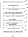
- Figure 3 is a flow diagram showing a series of steps that can be undertaken in an embodiment of the invention.
- the motor 16 is configured to scan the sensor 2 across the full range of movement required to survey the scene. In this example the motor 16 can rotate the sensor 2 smoothly from ⁇ min to ⁇ max . Readings are captured from each waveband in the sensor 2 at intervals of 0.1°.
- the central control unit 14 is configured to construct an infra-red profile which would normally be a plot of the temperature at each position between ⁇ min and ⁇ max .
- Figure 4 is an example of such a profile.
- other profiles based on the amount of radiation received by the sensor 2 as a function of position, such as signal strength or radiance may be plotted.
- the central control unit 14 is configured to identify regions in the profile where the temperature or the amount of infra-red radiation is greater than a first threshold value.
- the threshold value may be a proportion of the maximum value seen within the profile, or it may be a preset value based on the known temperature range of the extruded material, or it may be related to the previous temperature seen in the previous scan. In the example of Figure 4 , five such regions are identified with angular values of ⁇ 1 , ⁇ 2 , ⁇ 3 , ⁇ 4 and ⁇ 5 .
- a minimum width value may be used to eliminate noise or reflections, which in this case would eliminate ⁇ 2 , ⁇ 3 and ⁇ 4 .
- the regions at ⁇ 1 , ⁇ 5 are identified as hot extruded bodies because they have high signal strength values and are relatively broad.
- the central control unit 14 is configured to determine the optimum hot region for measurement. This may include selecting the hot region with the highest maximum temperature. Alternatively, the central control unit 14 could be configured to favour a wider but slightly cooler region by calculating the product of maximum temperature and the angular width of the region at the threshold value. In this example the extruded body at ⁇ 1 yields a higher value than the extruded body at ⁇ 5 for the product of maximum amount of infra-red radiation received and the width of the region.
- the temperature of a plurality of extruded bodies can be monitored in this way and, if necessary, compared. Any difference between the temperatures of these bodies may be indicative of a fault or an alarm condition. In one example, a difference in temperature may be indicative of a die cavity 24, 26 that is starting to become blocked. Such a condition can lead to thinner extrusions that are produced with increased temperature, and this can be detected using the present technique. Additionally, a plurality of extruded bodies can be monitored during quenching or at the quench exit. Differences in temperature at this stage can be indicative of uneven air or water cooling which may produce undesirable differences in product properties between the different extrusions.
- regions that correspond to hot extruded bodies in a temperature profile have a 'top hat' shape: they have a broad peak that is relatively flat and sides with steep edges. If a single wavelength thermometer is used or if the profile is plotted as radiance or signal strength against position, the peaks would have more gradually sloping edges.
- the top hat peak profile is generated by the ratio or algorithm method compensating for the signal loss when the sensor 2 starts to become misaligned with the extruded body so that less than 100% of the receiver area of the sensor 2 is aligned with the hot surface of the target. This is desirable so that the correct temperature can be measured in positions of partial misalignment. However, it is preferable to measure within the middle of an extrusion so that small movements are less likely to move the extrusion completely beyond the view of the sensor 2, and so that the signal strength is optimum leading to a more accurate less noisy temperature measurement.
- the central control unit 14 instructs the motor 16 to move the sensor 2 to ⁇ 1 so that it points at the first extruded body.
- the sensor 2 can therefore monitor the temperature of the extruded body in a continuous way and the central control unit 14 can provide feedback signals to adjust system parameters in order to maintain a constant temperature in the extruded bodies.
- the signal strength is also monitored, either as the signal strength value p, the raw radiance value of the infrared signal, or as an apparent change in the emissivity of the material.
- Steps 110 and 112 demonstrate a tracking mode for locations where the extrusion position is not well defined such as post-quench locations.
- a mini-scan is performed in order to maintain alignment between the sensor 2 and the selected extrusion.
- the motor 16 rotates the sensor 2 slightly to one side of the extrusion and then to the other.
- the angular range of the mini-scan is much smaller than the full scan at step 100, perhaps around 0.1° in either direction.
- the purpose of the mini-scan is to identify and correct for slight lateral movement of the extruded body as will occur naturally with increasing distance from the press exit if the profiles are not restrained.
- a mini infra-red profile is constructed by the central control unit 14 for the range of movement covered in the mini-scan.
- the profile will normally be plotted as signal strength, radiance, or apparent emissivity.
- the maximum value in the mini-scan will be identified as the position of this maximum value.
- the sensor 2 can then be moved by the motor 16 so that it is re-pointed at the centre of the extruded body, if any lateral movement is identified.
- one or more conditions can be detected by the central control unit 14 that would prompt the system to perform a new scan.
- One example condition is replacement of the extrusion die 22.
- a new extrusion die 22 with new cavities will require re-alignment of the sensor 2.
- the control system of the extrusion press will be configured to automatically trigger one or more scans following die change. In other embodiments scans may be triggered manually by press control operators.
- replacement of an extrusion die can be detected by a sensor such as an optical sensor or a mechanical switch, or by the cessation of infra-red measurements from a sensor 2 mounted close to the press exit
- a scan may also be triggered at step 114 if any of the measured temperature, the signal strength value, the raw radiation received or the apparent emissivity fall below a predetermined threshold level.
- Scans may be triggered immediately after die change; at predetermined time intervals following die change; or on particular billets following die change to correct for small changes in alignment, for example the first and second billets then every fifth billet.
- the central control unit 14 or the manual controller 4 could be used to point the sensor 2 at other identified extrusions in the scene.
- the sensor 2 can be pointed at the second extrusion produced by the die 22 at angle ⁇ 5 .
Landscapes
- Physics & Mathematics (AREA)
- General Physics & Mathematics (AREA)
- Spectroscopy & Molecular Physics (AREA)
- Engineering & Computer Science (AREA)
- Mechanical Engineering (AREA)
- Radiation Pyrometers (AREA)
Claims (10)
- Appareil pour aligner automatiquement un capteur infrarouge (2) sur un corps extrudé chaud (28, 30), comprenant :un capteur infrarouge (2) présentant un axe le long duquel un rayonnement est reçu ;un dispositif de balayage configuré pour déplacer (100) le capteur infrarouge (2) entre une pluralité de positions de telle sorte que l'axe du capteur infrarouge (2) soit pointé dans une pluralité de directions ; et un processeur configuré pour :analyser (102) la quantité de rayonnement infrarouge reçue dans la pluralité de positions pour déterminer un profil infrarouge ;identifier (104) une première position dans laquelle l'axe du capteur infrarouge (2) pointe au niveau d'un premier corps extrudé (28, 30) sur la base du profil infrarouge ;donner comme instruction (108) au dispositif de balayage de déplacer le capteur infrarouge (2) vers la première position de telle sorte que la température du premier corps extrudé (28, 30) puisse être mesurée ;donner comme instruction (110) au dispositif de balayage de déplacer le capteur infrarouge (2) entre une pluralité de positions de chaque côté de la première position ;construire (112) un second profil infrarouge sur la base du rayonnement reçu aux positions de chaque côté de la première position ; etdéterminer si le corps extrudé (28, 30) s'est déplacé latéralement sur la base du second profil infrarouge et, si un déplacement latéral est identifié, le processeur est en outre configuré pour donner comme instruction au capteur infrarouge (2) de se déplacer vers une nouvelle position de telle sorte qu'il puisse continuer à pointer au niveau du corps extrudé (28, 30).
- Appareil selon la revendication 1, dans lequel le dispositif de balayage est déclenché pour fonctionner lorsqu'il est déterminé qu'une filière d'extrusion (22) a changé.
- Appareil selon la revendication 1 ou la revendication 2, dans lequel le dispositif de balayage est déclenché pour fonctionner si la quantité de rayonnement infrarouge reçue avec le capteur infrarouge (2) dans la première position change d'une quantité prédéterminée.
- Appareil selon une quelconque revendication précédente, dans lequel le processeur est configuré pour identifier une pluralité de régions dans lesquelles la quantité de rayonnement infrarouge reçue est élevée et dans lequel le processeur est configuré pour identifier la première position sur la base d'une fonction de la largeur et de la quantité de rayonnement infrarouge reçue dans les régions respectives.
- Appareil selon une quelconque précédente, dans lequel le dispositif de balayage est agencé pour faire tourner le capteur infrarouge (2) de telle sorte qu'il soit pointé dans des directions différentes.
- Appareil selon une quelconque des revendications 1 à 4, dans lequel le dispositif de balayage est agencé pour déplacer le capteur infrarouge (2) en translation de telle sorte qu'il soit pointé le long d'axes parallèles différents.
- Appareil selon une quelconque revendication précédente, dans lequel le processeur est configuré pour identifier une seconde position dans laquelle l'axe du capteur infrarouge (2) pointe au niveau d'un second corps extrudé (28, 30) en mesurant la quantité de rayonnement reçue dans la seconde position et dans une pluralité de positions autour de la seconde position et dans lequel le processeur est configuré pour donner comme instruction au dispositif de balayage de déplacer le capteur infrarouge (2) vers la seconde position de telle sorte que la température du second corps extrudé (28, 30) puisse être mesurée.
- Appareil selon une quelconque revendication précédente, dans lequel le processeur est configuré pour déterminer des valeurs de température sur la base de la quantité de rayonnement infrarouge reçue dans la pluralité de positions et dans lequel la première position du capteur infrarouge (2) est identifiée sur la base de la valeur de température dans la première position et dans une pluralité de positions autour de la première position.
- Procédé d'alignement automatique d'un capteur infrarouge (2) sur un corps extrudé chaud (28, 30), comprenant :le déplacement (100) d'un capteur infrarouge (2) entre une pluralité de positions de telle sorte qu'un axe du capteur infrarouge (2) soit pointé dans une pluralité de directions et que le capteur infrarouge (2) reçoive un rayonnement infrarouge dans la pluralité de positions ;l'analyse (102) de la quantité de rayonnement infrarouge reçue dans la pluralité de positions pour déterminer un profil infrarouge ;l'identification (104) d'une première position dans laquelle l'axe du capteur infrarouge (2) pointe vers un premier corps extrudé (28, 30) sur la base du profil infrarouge ;le déplacement (108) du capteur infrarouge (2) vers la première position de telle sorte que la température du premier corps extrudé (28, 30) puisse être mesurée ;l'instruction (110) donnée au dispositif de balayage de déplacer le capteur infrarouge (2) entre une pluralité de positions de chaque côté de la première position ;la construction (112) d'un second profil infrarouge sur la base du rayonnement reçu dans les positions de chaque côté de la première position ; etla détermination pour savoir si le corps extrudé (28, 30) s'est déplacé latéralement sur la base du second profil infrarouge et, si un déplacement latéral est identifié, le procédé comprend en outre l'instruction donnée au capteur infrarouge (2) de se déplacer vers une nouvelle position de telle sorte qu'il puisse continuer à pointer vers le corps extrudé (28, 30).
- Produit programme informatique comprenant des instructions exécutables pour aligner automatiquement un capteur infrarouge (2) sur un corps extrudé chaud (28, 30) qui, lorsqu'elles sont exécutées sur un ordinateur, lorsqu'il est connecté à un capteur infrarouge (2) présentant un axe le long duquel le rayonnement est reçu et un dispositif de balayage configuré pour déplacer le capteur infrarouge (2) entre une pluralité de positions de telle sorte que l'axe du capteur infrarouge (2) soit pointé dans une pluralité de directions, amènent l'ordinateur à effectuer des étapes comprenant :le déplacement (100) du capteur infrarouge (2) entre une pluralité de positions de telle sorte qu'un axe du capteur infrarouge (2) soit pointé dans une pluralité de directions et que le capteur infrarouge (2) reçoive un rayonnement infrarouge dans la pluralité de positions ;l'analyse (102) de la quantité de rayonnement infrarouge reçue dans la pluralité de positions pour déterminer un profil infrarouge ;l'identification (104) d'une première position dans laquelle l'axe du capteur infrarouge (2) pointe vers un premier corps extrudé (28, 30) sur la base du profil infrarouge ;le déplacement (108) du capteur infrarouge (2) vers la première position de telle sorte que la température du premier corps extrudé (28, 30) puisse être mesurée ;l'instruction (110) donnée au dispositif de balayage de déplacer le capteur infrarouge (2) entre une pluralité de positions de chaque côté de la première position ;la construction (112) d'un second profil infrarouge sur la base du rayonnement reçu dans les positions de chaque côté de la première position ; etla détermination pour savoir si le corps extrudé (28, 30) s'est déplacé latéralement sur la base du second profil infrarouge et, si un déplacement latéral est identifié, les étapes comprennent en outre l'instruction donnée au capteur infrarouge (2) de se déplacer vers une nouvelle position de telle sorte qu'il puisse continuer à pointer vers le corps extrudé (28, 30).
Applications Claiming Priority (2)
| Application Number | Priority Date | Filing Date | Title |
|---|---|---|---|
| GB1803772.1A GB2574571A (en) | 2018-03-09 | 2018-03-09 | Alignment system for an infra-red sensor |
| PCT/GB2019/050641 WO2019171065A1 (fr) | 2018-03-09 | 2019-03-07 | Système d'alignement destiné à un capteur infrarouge |
Publications (3)
| Publication Number | Publication Date |
|---|---|
| EP3762693A1 EP3762693A1 (fr) | 2021-01-13 |
| EP3762693B1 true EP3762693B1 (fr) | 2023-12-20 |
| EP3762693C0 EP3762693C0 (fr) | 2023-12-20 |
Family
ID=61972747
Family Applications (1)
| Application Number | Title | Priority Date | Filing Date |
|---|---|---|---|
| EP19711677.5A Active EP3762693B1 (fr) | 2018-03-09 | 2019-03-07 | Système d'alignement destiné à un capteur infrarouge |
Country Status (4)
| Country | Link |
|---|---|
| EP (1) | EP3762693B1 (fr) |
| ES (1) | ES2968650T3 (fr) |
| GB (1) | GB2574571A (fr) |
| WO (1) | WO2019171065A1 (fr) |
Families Citing this family (1)
| Publication number | Priority date | Publication date | Assignee | Title |
|---|---|---|---|---|
| CN111343209B (zh) * | 2020-05-21 | 2020-08-25 | 浙江双视红外科技股份有限公司 | 一种具有温度信息的图片处理方法 |
Family Cites Families (6)
| Publication number | Priority date | Publication date | Assignee | Title |
|---|---|---|---|---|
| US3101618A (en) * | 1960-11-15 | 1963-08-27 | Leeds & Northrup Co | Rotary kiln shell temperature scanning system |
| JPS6051654A (ja) * | 1983-08-29 | 1985-03-23 | 鈴木 篁 | 窯業原料の脱鉄精製法 |
| US5144122A (en) * | 1990-10-19 | 1992-09-01 | Square D Company | Scanning radiation sensor with automatic focus control for optimal focus and method |
| JPH11179426A (ja) * | 1997-12-18 | 1999-07-06 | Toshiba Corp | 線材温度測定装置およびそれを用いた伸線機 |
| US7498576B2 (en) * | 2005-12-12 | 2009-03-03 | Suren Systems, Ltd. | Temperature detecting system and method |
| TW201042580A (en) * | 2009-05-25 | 2010-12-01 | Lung-Tsai Li | Temperature monitoring system for the entire region of environment |
-
2018
- 2018-03-09 GB GB1803772.1A patent/GB2574571A/en not_active Withdrawn
-
2019
- 2019-03-07 EP EP19711677.5A patent/EP3762693B1/fr active Active
- 2019-03-07 WO PCT/GB2019/050641 patent/WO2019171065A1/fr not_active Ceased
- 2019-03-07 ES ES19711677T patent/ES2968650T3/es active Active
Also Published As
| Publication number | Publication date |
|---|---|
| ES2968650T3 (es) | 2024-05-13 |
| GB201803772D0 (en) | 2018-04-25 |
| GB2574571A (en) | 2019-12-18 |
| EP3762693A1 (fr) | 2021-01-13 |
| WO2019171065A1 (fr) | 2019-09-12 |
| EP3762693C0 (fr) | 2023-12-20 |
Similar Documents
| Publication | Publication Date | Title |
|---|---|---|
| JP7126012B2 (ja) | 校正デバイスを備えた製品の付加製造のための装置及びこの装置の校正方法 | |
| EP2243012B1 (fr) | Procédé et appareil pour mesurer la température d'un matériau en feuille | |
| EP3168613B1 (fr) | Dispositif de détection de défauts par ultrasons et procédé de détection de défauts par ultrasons | |
| EP3065909B1 (fr) | Détection et analyse d'énergie thermique pour procédés de soudage | |
| US20150258626A1 (en) | Height Control and Deposition Measurement for the Electron Beam Free Form Fabrication (EBF3) Process | |
| US20200023575A1 (en) | System for Additive Manufacturing Processes and Related Control Method | |
| US20100236310A1 (en) | Edge flatness monitoring | |
| EP3762693B1 (fr) | Système d'alignement destiné à un capteur infrarouge | |
| WO2012171627A1 (fr) | Procédé et dispositif pour déterminer une caractéristique de suivi et/ou une largeur de bande d'une bande mobile | |
| Usamentiaga et al. | High-speed temperature monitoring for steel strips using infrared line scanners | |
| KR101770232B1 (ko) | 미지의 정도의 방출을 가지는 이동 오브젝트의 온도를 무접촉으로 결정하는 방법 및 디바이스 | |
| US5237844A (en) | Device to control the temperature of extruded metallic sections during the extrusion step | |
| EP3729026A1 (fr) | Système de mesure pour ligne de production de bande métallique | |
| CN113588091A (zh) | 一种利用高光谱实时测量激光选区金属熔池温度的系统和方法 | |
| US20220205842A1 (en) | A non-contact temperature sensor | |
| EP0314276B1 (fr) | Appareil et procédé de mesure sans contact | |
| JP6015084B2 (ja) | 長尺体の長さ測定方法及び装置 | |
| CN115112249B (zh) | 一种基于熔池温度梯度特性的液相金属发射率标定方法 | |
| JP5768477B2 (ja) | 被加工材の温度測定方法、加工品の製造方法、及び被加工材の加熱装置 | |
| JP2576298B2 (ja) | 管の測長方法及び装置 | |
| GB2582787A (en) | Temperature mapping apparatus and method | |
| US4290182A (en) | Methods and apparatus for measuring the temperature of a continuously moving strand of material | |
| Turner | Smart aluminium temperature sensors for Industry 4.0 | |
| US8536514B2 (en) | Method and apparatus for measuring the temperature of a sheet material | |
| Gagg | Aluminium temperature measurement developments |
Legal Events
| Date | Code | Title | Description |
|---|---|---|---|
| STAA | Information on the status of an ep patent application or granted ep patent |
Free format text: STATUS: UNKNOWN |
|
| STAA | Information on the status of an ep patent application or granted ep patent |
Free format text: STATUS: THE INTERNATIONAL PUBLICATION HAS BEEN MADE |
|
| PUAI | Public reference made under article 153(3) epc to a published international application that has entered the european phase |
Free format text: ORIGINAL CODE: 0009012 |
|
| STAA | Information on the status of an ep patent application or granted ep patent |
Free format text: STATUS: REQUEST FOR EXAMINATION WAS MADE |
|
| 17P | Request for examination filed |
Effective date: 20200903 |
|
| AK | Designated contracting states |
Kind code of ref document: A1 Designated state(s): AL AT BE BG CH CY CZ DE DK EE ES FI FR GB GR HR HU IE IS IT LI LT LU LV MC MK MT NL NO PL PT RO RS SE SI SK SM TR |
|
| AX | Request for extension of the european patent |
Extension state: BA ME |
|
| DAV | Request for validation of the european patent (deleted) | ||
| DAX | Request for extension of the european patent (deleted) | ||
| STAA | Information on the status of an ep patent application or granted ep patent |
Free format text: STATUS: EXAMINATION IS IN PROGRESS |
|
| 17Q | First examination report despatched |
Effective date: 20230519 |
|
| GRAP | Despatch of communication of intention to grant a patent |
Free format text: ORIGINAL CODE: EPIDOSNIGR1 |
|
| STAA | Information on the status of an ep patent application or granted ep patent |
Free format text: STATUS: GRANT OF PATENT IS INTENDED |
|
| INTG | Intention to grant announced |
Effective date: 20230712 |
|
| RIN1 | Information on inventor provided before grant (corrected) |
Inventor name: TURNER, SUSAN FIONA |
|
| GRAS | Grant fee paid |
Free format text: ORIGINAL CODE: EPIDOSNIGR3 |
|
| GRAA | (expected) grant |
Free format text: ORIGINAL CODE: 0009210 |
|
| STAA | Information on the status of an ep patent application or granted ep patent |
Free format text: STATUS: THE PATENT HAS BEEN GRANTED |
|
| AK | Designated contracting states |
Kind code of ref document: B1 Designated state(s): AL AT BE BG CH CY CZ DE DK EE ES FI FR GB GR HR HU IE IS IT LI LT LU LV MC MK MT NL NO PL PT RO RS SE SI SK SM TR |
|
| REG | Reference to a national code |
Ref country code: GB Ref legal event code: FG4D |
|
| REG | Reference to a national code |
Ref country code: CH Ref legal event code: EP |
|
| REG | Reference to a national code |
Ref country code: DE Ref legal event code: R096 Ref document number: 602019043559 Country of ref document: DE |
|
| REG | Reference to a national code |
Ref country code: IE Ref legal event code: FG4D |
|
| U01 | Request for unitary effect filed |
Effective date: 20240105 |
|
| U07 | Unitary effect registered |
Designated state(s): AT BE BG DE DK EE FI FR IT LT LU LV MT NL PT SE SI Effective date: 20240117 |
|
| U20 | Renewal fee for the european patent with unitary effect paid |
Year of fee payment: 6 Effective date: 20240207 |
|
| PG25 | Lapsed in a contracting state [announced via postgrant information from national office to epo] |
Ref country code: GR Free format text: LAPSE BECAUSE OF FAILURE TO SUBMIT A TRANSLATION OF THE DESCRIPTION OR TO PAY THE FEE WITHIN THE PRESCRIBED TIME-LIMIT Effective date: 20240321 |
|
| PG25 | Lapsed in a contracting state [announced via postgrant information from national office to epo] |
Ref country code: GR Free format text: LAPSE BECAUSE OF FAILURE TO SUBMIT A TRANSLATION OF THE DESCRIPTION OR TO PAY THE FEE WITHIN THE PRESCRIBED TIME-LIMIT Effective date: 20240321 |
|
| REG | Reference to a national code |
Ref country code: ES Ref legal event code: FG2A Ref document number: 2968650 Country of ref document: ES Kind code of ref document: T3 Effective date: 20240513 |
|
| PG25 | Lapsed in a contracting state [announced via postgrant information from national office to epo] |
Ref country code: RS Free format text: LAPSE BECAUSE OF FAILURE TO SUBMIT A TRANSLATION OF THE DESCRIPTION OR TO PAY THE FEE WITHIN THE PRESCRIBED TIME-LIMIT Effective date: 20231220 Ref country code: NO Free format text: LAPSE BECAUSE OF FAILURE TO SUBMIT A TRANSLATION OF THE DESCRIPTION OR TO PAY THE FEE WITHIN THE PRESCRIBED TIME-LIMIT Effective date: 20240320 Ref country code: HR Free format text: LAPSE BECAUSE OF FAILURE TO SUBMIT A TRANSLATION OF THE DESCRIPTION OR TO PAY THE FEE WITHIN THE PRESCRIBED TIME-LIMIT Effective date: 20231220 |
|
| PG25 | Lapsed in a contracting state [announced via postgrant information from national office to epo] |
Ref country code: IS Free format text: LAPSE BECAUSE OF FAILURE TO SUBMIT A TRANSLATION OF THE DESCRIPTION OR TO PAY THE FEE WITHIN THE PRESCRIBED TIME-LIMIT Effective date: 20240420 |
|
| PG25 | Lapsed in a contracting state [announced via postgrant information from national office to epo] |
Ref country code: CZ Free format text: LAPSE BECAUSE OF FAILURE TO SUBMIT A TRANSLATION OF THE DESCRIPTION OR TO PAY THE FEE WITHIN THE PRESCRIBED TIME-LIMIT Effective date: 20231220 |
|
| PG25 | Lapsed in a contracting state [announced via postgrant information from national office to epo] |
Ref country code: SK Free format text: LAPSE BECAUSE OF FAILURE TO SUBMIT A TRANSLATION OF THE DESCRIPTION OR TO PAY THE FEE WITHIN THE PRESCRIBED TIME-LIMIT Effective date: 20231220 |
|
| PG25 | Lapsed in a contracting state [announced via postgrant information from national office to epo] |
Ref country code: SM Free format text: LAPSE BECAUSE OF FAILURE TO SUBMIT A TRANSLATION OF THE DESCRIPTION OR TO PAY THE FEE WITHIN THE PRESCRIBED TIME-LIMIT Effective date: 20231220 Ref country code: SK Free format text: LAPSE BECAUSE OF FAILURE TO SUBMIT A TRANSLATION OF THE DESCRIPTION OR TO PAY THE FEE WITHIN THE PRESCRIBED TIME-LIMIT Effective date: 20231220 Ref country code: RO Free format text: LAPSE BECAUSE OF FAILURE TO SUBMIT A TRANSLATION OF THE DESCRIPTION OR TO PAY THE FEE WITHIN THE PRESCRIBED TIME-LIMIT Effective date: 20231220 Ref country code: IS Free format text: LAPSE BECAUSE OF FAILURE TO SUBMIT A TRANSLATION OF THE DESCRIPTION OR TO PAY THE FEE WITHIN THE PRESCRIBED TIME-LIMIT Effective date: 20240420 Ref country code: CZ Free format text: LAPSE BECAUSE OF FAILURE TO SUBMIT A TRANSLATION OF THE DESCRIPTION OR TO PAY THE FEE WITHIN THE PRESCRIBED TIME-LIMIT Effective date: 20231220 |
|
| PG25 | Lapsed in a contracting state [announced via postgrant information from national office to epo] |
Ref country code: PL Free format text: LAPSE BECAUSE OF FAILURE TO SUBMIT A TRANSLATION OF THE DESCRIPTION OR TO PAY THE FEE WITHIN THE PRESCRIBED TIME-LIMIT Effective date: 20231220 |
|
| PG25 | Lapsed in a contracting state [announced via postgrant information from national office to epo] |
Ref country code: PL Free format text: LAPSE BECAUSE OF FAILURE TO SUBMIT A TRANSLATION OF THE DESCRIPTION OR TO PAY THE FEE WITHIN THE PRESCRIBED TIME-LIMIT Effective date: 20231220 |
|
| REG | Reference to a national code |
Ref country code: DE Ref legal event code: R097 Ref document number: 602019043559 Country of ref document: DE |
|
| PLBE | No opposition filed within time limit |
Free format text: ORIGINAL CODE: 0009261 |
|
| STAA | Information on the status of an ep patent application or granted ep patent |
Free format text: STATUS: NO OPPOSITION FILED WITHIN TIME LIMIT |
|
| REG | Reference to a national code |
Ref country code: CH Ref legal event code: PL |
|
| PG25 | Lapsed in a contracting state [announced via postgrant information from national office to epo] |
Ref country code: MC Free format text: LAPSE BECAUSE OF FAILURE TO SUBMIT A TRANSLATION OF THE DESCRIPTION OR TO PAY THE FEE WITHIN THE PRESCRIBED TIME-LIMIT Effective date: 20231220 |
|
| 26N | No opposition filed |
Effective date: 20240923 |
|
| PG25 | Lapsed in a contracting state [announced via postgrant information from national office to epo] |
Ref country code: MC Free format text: LAPSE BECAUSE OF FAILURE TO SUBMIT A TRANSLATION OF THE DESCRIPTION OR TO PAY THE FEE WITHIN THE PRESCRIBED TIME-LIMIT Effective date: 20231220 |
|
| PG25 | Lapsed in a contracting state [announced via postgrant information from national office to epo] |
Ref country code: IE Free format text: LAPSE BECAUSE OF NON-PAYMENT OF DUE FEES Effective date: 20240307 |
|
| PG25 | Lapsed in a contracting state [announced via postgrant information from national office to epo] |
Ref country code: IE Free format text: LAPSE BECAUSE OF NON-PAYMENT OF DUE FEES Effective date: 20240307 Ref country code: CH Free format text: LAPSE BECAUSE OF NON-PAYMENT OF DUE FEES Effective date: 20240331 |
|
| U20 | Renewal fee for the european patent with unitary effect paid |
Year of fee payment: 7 Effective date: 20250205 |
|
| PGFP | Annual fee paid to national office [announced via postgrant information from national office to epo] |
Ref country code: ES Payment date: 20250411 Year of fee payment: 7 |
|
| PG25 | Lapsed in a contracting state [announced via postgrant information from national office to epo] |
Ref country code: CY Free format text: LAPSE BECAUSE OF FAILURE TO SUBMIT A TRANSLATION OF THE DESCRIPTION OR TO PAY THE FEE WITHIN THE PRESCRIBED TIME-LIMIT; INVALID AB INITIO Effective date: 20190307 |
|
| PG25 | Lapsed in a contracting state [announced via postgrant information from national office to epo] |
Ref country code: HU Free format text: LAPSE BECAUSE OF FAILURE TO SUBMIT A TRANSLATION OF THE DESCRIPTION OR TO PAY THE FEE WITHIN THE PRESCRIBED TIME-LIMIT; INVALID AB INITIO Effective date: 20190307 |
|
| PG25 | Lapsed in a contracting state [announced via postgrant information from national office to epo] |
Ref country code: TR Free format text: LAPSE BECAUSE OF FAILURE TO SUBMIT A TRANSLATION OF THE DESCRIPTION OR TO PAY THE FEE WITHIN THE PRESCRIBED TIME-LIMIT Effective date: 20231220 |
|
| U20 | Renewal fee for the european patent with unitary effect paid |
Year of fee payment: 8 Effective date: 20260209 |
|
| PGFP | Annual fee paid to national office [announced via postgrant information from national office to epo] |
Ref country code: GB Payment date: 20260106 Year of fee payment: 8 |