EP3763265B1 - Aspirateur portatif - Google Patents
Aspirateur portatif Download PDFInfo
- Publication number
- EP3763265B1 EP3763265B1 EP19186088.1A EP19186088A EP3763265B1 EP 3763265 B1 EP3763265 B1 EP 3763265B1 EP 19186088 A EP19186088 A EP 19186088A EP 3763265 B1 EP3763265 B1 EP 3763265B1
- Authority
- EP
- European Patent Office
- Prior art keywords
- intermediate element
- suction
- vacuum apparatus
- portable vacuum
- electric motor
- Prior art date
- Legal status (The legal status is an assumption and is not a legal conclusion. Google has not performed a legal analysis and makes no representation as to the accuracy of the status listed.)
- Active
Links
Images



Classifications
-
- A—HUMAN NECESSITIES
- A47—FURNITURE; DOMESTIC ARTICLES OR APPLIANCES; COFFEE MILLS; SPICE MILLS; SUCTION CLEANERS IN GENERAL
- A47L—DOMESTIC WASHING OR CLEANING; SUCTION CLEANERS IN GENERAL
- A47L9/00—Details or accessories of suction cleaners, e.g. mechanical means for controlling the suction or for effecting pulsating action; Storing devices specially adapted to suction cleaners or parts thereof; Carrying-vehicles specially adapted for suction cleaners
- A47L9/22—Mountings for motor fan assemblies
-
- A—HUMAN NECESSITIES
- A47—FURNITURE; DOMESTIC ARTICLES OR APPLIANCES; COFFEE MILLS; SPICE MILLS; SUCTION CLEANERS IN GENERAL
- A47L—DOMESTIC WASHING OR CLEANING; SUCTION CLEANERS IN GENERAL
- A47L1/00—Cleaning windows
- A47L1/02—Power-driven machines or devices
- A47L1/05—Hand apparatus with built-in electric motors
-
- A—HUMAN NECESSITIES
- A47—FURNITURE; DOMESTIC ARTICLES OR APPLIANCES; COFFEE MILLS; SPICE MILLS; SUCTION CLEANERS IN GENERAL
- A47L—DOMESTIC WASHING OR CLEANING; SUCTION CLEANERS IN GENERAL
- A47L7/00—Suction cleaners adapted for additional purposes; Tables with suction openings for cleaning purposes; Containers for cleaning articles by suction; Suction cleaners adapted to cleaning of brushes; Suction cleaners adapted to taking-up liquids
- A47L7/0004—Suction cleaners adapted to take up liquids, e.g. wet or dry vacuum cleaners
- A47L7/0023—Recovery tanks
-
- A—HUMAN NECESSITIES
- A47—FURNITURE; DOMESTIC ARTICLES OR APPLIANCES; COFFEE MILLS; SPICE MILLS; SUCTION CLEANERS IN GENERAL
- A47L—DOMESTIC WASHING OR CLEANING; SUCTION CLEANERS IN GENERAL
- A47L7/00—Suction cleaners adapted for additional purposes; Tables with suction openings for cleaning purposes; Containers for cleaning articles by suction; Suction cleaners adapted to cleaning of brushes; Suction cleaners adapted to taking-up liquids
- A47L7/0004—Suction cleaners adapted to take up liquids, e.g. wet or dry vacuum cleaners
- A47L7/0042—Gaskets; Sealing means
-
- A—HUMAN NECESSITIES
- A47—FURNITURE; DOMESTIC ARTICLES OR APPLIANCES; COFFEE MILLS; SPICE MILLS; SUCTION CLEANERS IN GENERAL
- A47L—DOMESTIC WASHING OR CLEANING; SUCTION CLEANERS IN GENERAL
- A47L9/00—Details or accessories of suction cleaners, e.g. mechanical means for controlling the suction or for effecting pulsating action; Storing devices specially adapted to suction cleaners or parts thereof; Carrying-vehicles specially adapted for suction cleaners
- A47L9/0081—Means for exhaust-air diffusion; Means for sound or vibration damping
Definitions
- the invention relates to a portable suction device according to the preamble of claim 1.
- the invention relates to a portable suction device with a suction channel opening into a suction nozzle and with a housing, a suction material container and a suction unit having at least one electric motor, an accumulator and a fan wheel for generating a suction flow, which provides a negative suction pressure applied to the suction nozzle, and with a separating device, which is able to divide the suction flow sucked in via the suction nozzle into an exhaust air flow flowing out of the suction device and into suction material in the form of particles and/or fluid components, the separated particles or Fluid components are collected in the suction material container.
- these devices also have a pull-off lip for removing liquids, with the pull-off lip being arranged on the suction nozzle.
- these devices are usually battery operated and are held in a user's hand while the user guides the squeegee along the surface to be vacuumed.
- Portable devices of this type are among others from the EP 2 845 530 B1 and EP 0 170 720 A2 known.
- the known suction devices are used to suck up a liquid/air mixture. As in the case of the device mentioned, this can be done for sucking up liquid, for example from a flat surface such as a table top, window panes or tiles.
- a squeegee lip arranged on the suction nozzle is provided in the devices of the generic type.
- EP 3 021 723 A1 describes a portable suction device that provides a separate waterproof unit that includes the electric motor, the accumulator and the component electronics.
- the separate unit is installed in the housing of the suction device.
- the encapsulation due to the separate unit within the housing of the electric motor, battery and electronics leads to increased heating of the components, in particular the electric motor, but also the temperature-sensitive battery. This results from the multi-layer structure, which accordingly causes undesirable insulation with poor heat dissipation.
- the service life of the components can be reduced due to the increased heating.
- the usage time can also be reduced if the device has to be switched off due to overheating.
- the object of the invention is therefore to provide a portable suction device which allows the electronic components to be sealed against the ingress of suction material while at the same time providing good heat dissipation and cost-effective production.
- the portable suction device provides that part of the suction container boundary has a receiving area for receiving electronic components of the suction device, the receiving area being formed in the form of at least one cavity that is watertight except for the opening and is designed to be watertightly closable by a separate intermediate element.
- the electronic components include at least the electric motor and the accumulator, but can also include other electronic components, such as monitoring and/or control elements arranged on a printed circuit board.
- the cavity can consist of one or more pockets, with the individual electronic components being arranged in the pockets.
- the electronic components are protected against the ingress of dust and water by the watertight sealed cavity in the suction container. Furthermore, the arrangement does not have any heat-insulating encapsulation of the components, so that the heat loss occurring during operation of the device can be dissipated easily. This can be done directly via the housing to the environment and also in the vacuumed suction.
- the intermediate element preferably forms a component carrier, by which at least the electric motor and the accumulator are held.
- the fan wheel is advantageously arranged and rotatably mounted on the side of the intermediate element facing away from the receiving area.
- the construction according to the invention is advantageous in terms of production and thus in terms of costs, since the intermediate element is used to form a preassembled assembly that can be used as a whole in one assembly step.
- the intermediate element can preferably be designed geometrically in the form of component receiving elements in such a way that at least the electric motor and/or the accumulator can be received in a defined manner.
- Individual pockets or receptacles or also ribs can be provided in the intermediate element.
- the electronic components are inserted and held in these. It is advantageous if, for example, the electric motor and the accumulator as well as any printed circuit board with measuring and control elements are arranged in separate pockets.
- the walls of the pockets at least partially insulate the electronic components from one another, so that the waste heat from the electric motor does not additionally heat up the accumulator or the circuit board.
- the pockets are preferably designed in such a way that, on the one hand, good heat dissipation of the components and thermal insulation between the electronic components is achieved. On the other hand, in such a way that the electronic components are held securely in the pockets. This can be realized, for example, by pockets with walls of different heights and/or recesses within the pockets.
- soft elements can be arranged on the intermediate element and/or in the receiving area, with the electronic components, in particular the electric motor and/or the accumulator, softly mounted, are arranged in the intermediate element. This is advantageous when the intermediate element is constructed with a plurality of pockets in which the individual electronic components are accommodated.
- the soft elements are arranged and designed in such a way that the electronic components are held by the intermediate element without play.
- the soft tissue support also acts advantageously as a damper for the electronic components if the device is put down roughly or accidentally falls down.
- means are provided which are set up to improve the heat dissipation of the electronic components.
- the means can be formed by heat-conducting areas in the area of the intermediate element and/or in the area of the receiving area.
- the heat-conducting areas can be structurally formed by ribs or similar designs and/or can be achieved by a heat-conducting material combination.
- the thermally conductive areas can be formed by overmolded metal.
- the intermediate element and the component receiving elements of the intermediate element that accommodate the electronic components are preferably made of plastic.
- thermally conductive particles for example copper particles, can be added to the plastic.
- the geometry of the suction device is designed in such a way that the heat dissipation in the direction of the suction material container or suction material is higher than in the other directions.
- This can be realized, for example, in that at least part of the receiving area in the suction material container boundary is part of the suction device housing and/or is arranged close to the suction device housing.
- the intermediate element advantageously has a circumferential sealing contour as a sealing element.
- the cavity formed by the suction material container limitation The receiving area can have a one-sided and planar opening.
- the circumferential sealing contour of the intermediate element can be flat.
- Corresponding geometric configurations are provided on the housing and/or on the receiving area and on the intermediate element for the sealing closure of the receiving area. These are designed in such a way that the intermediate element is held in at least one direction and can close the receiving area.
- the intermediate element is preferably made as a two-component part from a hard plastic and a soft plastic that forms the soft elements.
- the seal of the intermediate element can also be injection molded.
- the fan wheel is arranged on the side of the intermediate element facing away from the receiving area and is driven by the electric motor.
- the intermediate element has a passage opening for the motor shaft.
- a motor shaft seal is provided to seal the motor shaft.
- the motor shaft seal can be molded on and/or mounted as a separate part on the intermediate element.
- a switching element for switching on the suction device can be provided as an electronic component, which is preferably arranged on a measuring and/or control circuit board.
- an elastic housing area can be provided above the switch, via which the switch can be actuated.
- the housing is preferably designed to be translucent in one area.
- An LED can be provided below the translucent area, which indicates operation of the suction device. This has the advantage that there is no need to provide a separate recess for the LED in the housing.
- the refinement enables a particularly attractive design.
- the LED can be arranged on the circuit board, for example.
- the shape of the suction device is such that the suction device extends into a handle of the suction device on the end section opposite the suction nozzle.
- the suction device 2 is shown in a side view.
- the suction device 2 is designed as a hand-operated window vacuum.
- the suction device 2 comprises a suction nozzle 4 designed as a flat nozzle with pull-off lips 5 arranged above and below the flat nozzle opening, which are detachably arranged on a beak-shaped receptacle 62 formed from two parallel planes via a clamp connection.
- the suction device 2 Pointing in the direction of flow, the suction device 2 has a suction and separating area adjoining the suction nozzle 4 , a suction unit 10 , a suction material container 8 and a closure 42 .
- the aforementioned components are accommodated in a housing 6 of the suction device 2 .
- the suction device 2 is initially bulbous in the area of the separation area and the suction unit 10 and then extends into a rear area, which forms a handle 48.
- the handle 48 terminates in the closure 42 at the distal end.
- the suction material container 8 is largely located in the handle 48 and extends to the end of the handle 48.
- An opening 40 is provided in the suction material container 8 at the distal end of the handle 48, which is sealed by the closure 42 to prevent suction material, in particular water, from escaping is.
- the housing 6 of the suction device 2 is designed in several parts. It includes an upper shell 64 which has ventilation slots 66 for the flow of exhaust air and a recess for a Operating button 68 for switching the device 2 on and off.
- the upper shell 64 of the housing 6 is fitted on a lower part of the housing.
- the lower part of the housing forms a part of the handle 48 as a handle shell 70, the handle 48 being made in several parts.
- the grip shell 70 in turn simultaneously forms a lower boundary of the suction material container 8.
- the suction and separation areas are each accommodated by a front part of the housing 6, which also forms the receptacle for the suction nozzle 62.
- the shape of the suction device 2 is designed in such a way that the device 2 is accommodated in two parking areas when it is parked on a level parking surface 72 .
- the two storage elements 74 are arranged at a distance from a longitudinal axis of the suction device 2 on both sides.
- a part of the closure 42 forms the second storage area.
- the two storage elements 74 allow the suction device 2 to be placed on the level storage surface 72 so that it is stable against tipping.
- the storage areas are arranged on the suction device 2 in such a way that the suction nozzle 4 and in particular the wiping lip 5 are at a distance from the level storage surface 72 .
- Both the outer area of the closure 42 and the shelf elements 74 designed as feet are made of a soft material, in particular a rubber-like material. In addition to a stable and surface-protecting stand of the device 2 when the device 2 is parked, this also avoids damage when the device 2 is used, if the device 2 does not come into contact with the surface to be cleaned or the surfaces around it as intended.
- FIG 2 shows a perspective view of the suction device 2 figure 1 .
- the upper part of the receptacle for the suction nozzle 62 can be seen, in which the suction nozzle 4 designed as a flat nozzle is releasably inserted via the clamp connection. Due to the detachable connection, other suction nozzles can also be used in the holder of the suction nozzle, depending on the area of application.
- the closure 42 continuing the outer contour of the device 2 is shown in the dismantled state at a distance from the suction device 2 .
- the closure 42 has a gripping area at the end, which is formed by a raised edge in the form of a retaining bead 76 in the rear area.
- FIG 3 shows a further view of the suction device 2 according to the invention from the previous figures.
- the suction device 2 is shown with the separation area cut free and without an upper housing shell 64 and without a closure 42 .
- the suction material sucked in by the suction nozzle 4 (not shown) is transferred to the separation area via a suction channel 3 arranged in the receptacle for the suction nozzle 62, and separated from the exhaust air flow by the separation device 12 and transferred into an inlet opening 36 arranged in the lower part of the suction device 2.
- the inlet opening 36 leads into the suction material guide 30 , via which the suction material is in turn guided into the suction material container 8 .
- the individual components of the separating device 12 can be seen in the cut-out area, which comprises a ramp-shaped vacuum material guide element 14 and a rotary separator 16 .
- the rotary separator 16 is connected in one piece to the fan wheel 11 of the suction unit 10 .
- the separation area is designed as a separation chamber 18 .
- the boundary forming the separation chamber 18 is designed in two parts.
- the first part is formed by a cup-shaped first delimiting element 92, in the bottom area of which the beak-shaped receptacle for the suction nozzle 62 is also formed.
- the cup-shaped delimiting element 92 is also part of the suction device housing 6 at the same time.
- the cover element 94 has two openings.
- the rotary separator 16 integrally connected to the fan wheel 11 is arranged in the first opening, which is arranged centrally in the cover element and is an exhaust air opening.
- the exhaust air flow freed from suction material is conveyed through the exhaust air opening from the separation chamber 18 via the fan wheel 11 through the ventilation slots 66 in the suction device housing 6 to the outside.
- the second opening is an outlet opening of the separation chamber 18 and is at the same time the inlet opening 36 into the suction material guide 30.
- a cover element 27 of the suction material container 8 with the suction unit 10 installed is shown in a side view.
- the cover element 27 is releasably connected to the handle shell 70 by a clamp connection.
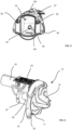
- a receiving area 22 for receiving the electronic components of the suction unit 10, in particular an electric motor 24, a circuit board 25 and an accumulator 26, is provided in the cover element 27, the receiving area 22 being formed in the form of a pocket-shaped cavity.
- the receiving area 22 designed as a cavity open on one side is designed in one piece in the housing cover 27 .
- the accumulator 26 and an underlying geometrically shorter pocket of the electric motor 24 was added.
- the receiving area 22 is designed in a stepped manner corresponding to the shape of the electronic components.
- the receiving area 22 is sealed by a separate intermediate element 23 to prevent suction material from escaping, the intermediate element 23 simultaneously acting as a component carrier for the electric motor 24 , the circuit board 25 and the accumulator 26 .
- Component receiving elements 28 for the electrical components are provided in the intermediate element 23 .
- the component receiving elements 28 are designed as holders in the form of hollow beams.
- the intermediate element 23 is carried both by the grip shell 70 and by the cover element 27 .
- centering openings 29 are distributed around the circumference in the radially outer region of the intermediate element 23 .
- the cover element 27 with the receiving area 22 is seen in an oblique view from the front in figure 5 shown.
- the receiving area 22 embodied as a hollow body has a rectangular cross-section with a rounded top and bottom on the side of the receiving area 22 facing the suction nozzle 4 .
- the rectangular cross-section is intended to accommodate the electric motor 24, the accumulator 26 and the circuit board 25 together with their respective supports.
- the geometrically longer pocket for the accumulator 26 is provided in the part of the receiving area 22 directed towards the upper side of the suction device 2 .
- a receptacle for a motor shaft bearing 87 of the electric motor 24 is provided in the part of the receiving area 22 that receives the electric motor 24 .
- This receptacle for the motor shaft bearing 87 is arranged concentrically with the electric motor 24 and with the fan wheel 11 driven by it.
- a bulge 89 is provided immediately next to the mount for the motor shaft bearing 87 . This acts as clearance for a soldering lug and a motor cable of the electric motor.
- a recess is also provided in the shell component in a shell component 32 which is arranged under the receiving area 22 and forms part of the vacuum material guide 30 .
- the recess and bulge 89 are structurally matched to one another in such a way that the receiving area 22 and the shell component 32 do not touch at this point.
- a cable opening 88 is provided in the lower wall of the receiving area 22 in the direction of the suction material guide 30 , through which the cables for a charging connection on the underside of the suction device 2 are fed through when the suction device 2 is in the installed state.
- a sealing element is provided on the underside of the receiving area 22, which seals the cable opening 88 in the receiving area 22 against the ingress of suction material. The sealing element is designed as a peripheral seal and interacts with a corresponding sealing groove on the shell component 32 .
- a part of the cover element 27, which is arranged above the actuating button 68 on the circuit board 25 when the suction device 2 is installed, is formed as an elastic housing area.
- the actuating button 68 can be actuated by a pressure load through the elastic housing area in order to switch the suction device 2 on and off.
- the elastic housing area is formed from a soft material, in particular a rubber-like material.
- a part of the elastic housing area is designed to be translucent. Furthermore, an LED is provided below the translucent area of the housing, which indicates an operating state of the suction device 2 .
- the handle shell 70 forms the bulbous part of the suction device 2 up to the end of the receiving area 22 pointing towards the closure 42 and from there merges into the handle 48 . In this way, a particularly advantageous use of space is achieved.
- FIG figures 6 and 7 A perspective front and rear view of the intermediate element 23 designed as a component carrier is shown in FIG figures 6 and 7 .
- the intermediate element 23 has four centering openings 29 which are distributed symmetrically over the intermediate element 23 .
- the upper part of the intermediate element 23 has a half-shell reinforced by ribs, which extends in the direction of the rotary separator 16 .
- the height of the half-shell is such that it is above the height of the radially outer area of the fan blades of the fan wheel 11 .
- In the illustrated embodiment extends the half-shell between two centering openings, the upper two. In this way, better support between the centering or positioning elements 90 of the cover element 27 and the centering openings 29 of the intermediate element 23 is achieved.
- the provision of the half-shell serves to discharge the flow of exhaust air out of the suction device 2 in a directed manner, in particular via the sides of the suction device 2 .
- a cover element designed as a plate-shaped delimiting element of the separation area is placed on the intermediate element 23 in the direction of the rotary separator and closes the area of the half-shell.
- the two lower centering openings 29 of the intermediate element 23 are positioned in the suction material guide 30 on both sides of the semicircular inlet opening 36 when the device is in the assembled state.
- the cover element 94 is placed on the inlet opening 36 in the suction material guide 30 in a sealing manner. Due to the laterally open areas formed between the intermediate element 23 and the cover element 94 , the exhaust air flow is guided out of the suction device 2 through the ventilation slots 66 in the upper housing cover 64 .
- a sealing element 58 designed as a circumferential seal, with the sealing element 58 being rectangular, corresponding to the rectangular opening of the receiving area 22, such that the intermediate element 23 seals the receiving area 22 against the ingress of suction material can.
- the seal is molded onto the intermediate element 23 and forms a flat sealing contour.
- the component receiving elements 28 in which the electric motor 24, the accumulator 26 and the circuit board 25 are held are provided spatially within the peripheral seal on the intermediate element 23 .
- the component receiving elements 28 are connected to the intermediate element 23 in one piece.
- the component receiving elements 28 do not completely enclose the electronic components in order to enable good heat dissipation but also good support for the components.
- a housing of the electric motor 24 has a rectangular cross section.
- the component receiving element 28 holding the electric motor 24 holds the electric motor 24 only on the housing covers, the part of the housing of the electric motor 24 facing away from the intermediate element 23 being less covered by the component receiving element 28 than the part facing the intermediate element 23 .
- the temperature-sensitive accumulator 26 in particular is at least partially shielded from the waste heat of the electric motor 24 .
- Inserted soft elements are provided in the component receiving elements 28 and in the receiving area 22 and are set up in such a way that the electronic components, in particular the electric motor 24 and the accumulator 26, are seated securely. Furthermore, soft elements are also provided on the outside of the component receiving elements 28 in order to also hold the component receiving elements 28 securely in the receiving area 22 .
Landscapes
- Engineering & Computer Science (AREA)
- Mechanical Engineering (AREA)
- Manipulator (AREA)
Claims (15)
- Aspirateur portatif (2) avec un canal d'aspiration (3) débouchant dans une buse d'aspiration (4) et avec un boîtier (6), un réservoir de produit à aspirer (8) et un agrégat d'aspiration (10) comprenant au moins un moteur électrique (24), un accumulateur (26) et une roue de ventilateur (11) pour générer un courant d'aspiration, qui fournit une dépression d'aspiration appliquée à la buse d'aspiration (4), et avec un dispositif de séparation (12) qui permet de diviser le flux d'aspiration aspiré par la buse d'aspiration (4) en un flux d'air d'évacuation s'écoulant hors de l'aspirateur portatif (2) et en matière aspirée sous forme de particules et/ou de parties de résidus de fluide, les particules ou les composants de fluide séparés étant collectés dans le récipient de produit aspiré (8), caractérisé en ce qu'une partie de la paroi du récipient de produit aspiré (8) comprend une partie de réception (22) pour recevoir au moins le moteur électrique (24) et l'accumulateur (26), la partie de réception (22) étant formée sous la forme d'au moins une cavité réalisée de manière étanche à l'eau à l'exception d'une ouverture et pouvant être fermée de manière étanche à l'eau par un élément intermédiaire séparé (23).
- Aspirateur portatif (2) selon la revendication 1, caractérisé en ce que l'élément intermédiaire (23) forme un support de composants par lequel sont maintenus au moins le moteur électrique (24) et l'accumulateur (26), la roue de ventilateur (11) étant disposée sur l'élément intermédiaire (23) sur la face de l'élément intermédiaire (23) opposée à la partie de réception (22) et étant logée de manière rotative.
- Aspirateur portatif (2) selon la revendication précédente, caractérisé en ce que des éléments souples sont disposés sur l'élément intermédiaire (23) et/ou dans la partie de réception (22), le moteur électrique (24) et/ou l'accumulateur (26) étant montés souples dans l'élément intermédiaire (23).
- Aspirateur portatif (2) selon la revendication précédente, caractérisé en ce que l'élément intermédiaire (23) est formé sous forme de pièce à deux composants en une matière plastique dure et une matière plastique souple formant les éléments souples.
- Aspirateur portatif (2) selon l'une des revendications précédentes, caractérisé en ce que l'élément intermédiaire (23) comprend un contour d'étanchéité périphérique, le contour d'étanchéité étant notamment plan.
- Aspirateur portatif (2) selon l'une des revendications précédentes, caractérisé en ce que l'élément intermédiaire (23) est configuré géométriquement de manière à recevoir de manière définie au moins le moteur électrique (24) et/ou l'accumulateur (26), notamment en prévoyant des géométries telles que des poches et des nervures.
- Aspirateur portatif (2) selon l'une des revendications précédentes, caractérisé en ce qu'il est prévu des éléments d'aiguillage supplémentaires qui sont agencés de manière à obtenir une assise sûre des composants électroniques, en particulier du moteur électrique (24) et de l'accumulateur (26).
- Aspirateur portatif (2) selon l'une des revendications précédentes, caractérisé en ce qu'il est prévu des moyens agencés pour améliorer la dissipation de chaleur des composants électroniques.
- Aspirateur portatif (2) selon la revendication précédente, caractérisé en ce que les moyens sont formés par des zones thermoconductrices au niveau de l'élément intermédiaire (23) et/ou au niveau de la partie de réception (22), les zones de thermocon-ductivité étant notamment formées par du métal surmoulé.
- Aspirateur portatif (2) selon l'une quelconque des revendications précédentes, caractérisé en ce qu'au moins des parties de l'élément intermédiaire (23) et/ou de la zone de réception (22) comprennent des matériaux thermoconducteurs, notamment du métal.
- Aspirateur portatif (2) selon l'une quelconque des revendications précédentes en combinaison avec la revendication 8, caractérisé en ce que l'élément intermédiaire (23) et les éléments de réception de composants de l'élément intermédiaire (23) recevant les composants électroniques sont formés en matière plastique, et en ce que les moyens sont formés par l'ajout de particules thermoconductrices dans la matière plastique, notamment du cuivre.
- Aspirateur portatif (2) selon l'une des revendications précédentes, caractérisé en ce que la géométrie de l'aspirateur portatif (2) est telle que la dissipation de chaleur est plus importante dans la direction du récipient (8) ou de la matière à aspirer que dans les autres directions.
- Aspirateur portatif (2) selon l'une des revendications précédentes, caractérisé en ce que l'élément intermédiaire (23) comprend une ouverture de passage pour l'arbre moteur (84) et en ce que l'élément intermédiaire (23) prévoit un joint d'étanchéité pour l'arbre moteur, le joint d'étanchéité pour l'arbre moteur étant notamment moulé par injection ou monté sur l'élément intermédiaire (23) en tant que pièce séparée.
- Aspirateur portatif (2) selon l'une des revendications précédentes, caractérisé en ce que des configurations géométriques correspondant les unes aux autres sont prévues sur le boîtier et/ou sur la partie de réception (22) ainsi que sur l'élément intermédiaire (23), de telle sorte que l'élément intermédiaire (23), maintenu dans au moins une direction, peut fermer la partie de réception (22).
- Aspirateur portatif (2) selon l'une quelconque des revendications précédentes, caractérisé en ce que l'élément intermédiaire (23) et au moins le moteur électrique (24) et l'accumulateur (26) forment un ensemble pré-assemblé.
Priority Applications (1)
| Application Number | Priority Date | Filing Date | Title |
|---|---|---|---|
| EP19186088.1A EP3763265B1 (fr) | 2019-07-12 | 2019-07-12 | Aspirateur portatif |
Applications Claiming Priority (1)
| Application Number | Priority Date | Filing Date | Title |
|---|---|---|---|
| EP19186088.1A EP3763265B1 (fr) | 2019-07-12 | 2019-07-12 | Aspirateur portatif |
Publications (3)
| Publication Number | Publication Date |
|---|---|
| EP3763265A1 EP3763265A1 (fr) | 2021-01-13 |
| EP3763265B1 true EP3763265B1 (fr) | 2023-06-07 |
| EP3763265C0 EP3763265C0 (fr) | 2023-06-07 |
Family
ID=67262196
Family Applications (1)
| Application Number | Title | Priority Date | Filing Date |
|---|---|---|---|
| EP19186088.1A Active EP3763265B1 (fr) | 2019-07-12 | 2019-07-12 | Aspirateur portatif |
Country Status (1)
| Country | Link |
|---|---|
| EP (1) | EP3763265B1 (fr) |
Cited By (1)
| Publication number | Priority date | Publication date | Assignee | Title |
|---|---|---|---|---|
| US12465183B2 (en) | 2024-03-04 | 2025-11-11 | Sharkninja Operating Llc | Handheld surface cleaner |
Families Citing this family (2)
| Publication number | Priority date | Publication date | Assignee | Title |
|---|---|---|---|---|
| DE102024202005A1 (de) * | 2024-03-04 | 2025-09-04 | BSH Hausgeräte GmbH | Saugeinheit mit Frischluftkühlung |
| USD1100392S1 (en) * | 2024-06-28 | 2025-10-28 | Hongliang Wu | Cordless vacuum cleaner |
Family Cites Families (3)
| Publication number | Priority date | Publication date | Assignee | Title |
|---|---|---|---|---|
| DE3429565A1 (de) * | 1984-08-10 | 1986-02-20 | H & H Industriebedarfs- und Handels GmbH, 5000 Köln | Kleinstaubsauger |
| WO2015007325A1 (fr) | 2013-07-18 | 2015-01-22 | Alfred Kärcher Gmbh & Co. Kg | Appareil de nettoyage de surfaces dures portable |
| DE202013104011U1 (de) | 2013-09-05 | 2013-09-18 | Leifheit Ag | Tragbares Sauggerät für Flüssigkeiten oder Flüssigkeits-/Luftgemische |
-
2019
- 2019-07-12 EP EP19186088.1A patent/EP3763265B1/fr active Active
Cited By (1)
| Publication number | Priority date | Publication date | Assignee | Title |
|---|---|---|---|---|
| US12465183B2 (en) | 2024-03-04 | 2025-11-11 | Sharkninja Operating Llc | Handheld surface cleaner |
Also Published As
| Publication number | Publication date |
|---|---|
| EP3763265A1 (fr) | 2021-01-13 |
| EP3763265C0 (fr) | 2023-06-07 |
Similar Documents
| Publication | Publication Date | Title |
|---|---|---|
| EP3763265B1 (fr) | Aspirateur portatif | |
| EP2431134B1 (fr) | Appareil manuel doté d'un moteur d'entraînement électrique | |
| EP1802524B1 (fr) | Bateau a moteur electrique a refroidissement par l'eau environnante | |
| DE19538252C2 (de) | Struktur eines Griffes für motorgetriebene Werkzeuge | |
| EP3393319B1 (fr) | Buse d'aspiration pour un appareil de nettoyage de surface dures et appareil de nettoyage de surfaces dures comportant une telle buse d'aspiration | |
| EP1505891B1 (fr) | Dispositif de nettoyage pour la tete de coupe d'un appareil de rasage a sec | |
| DE3220644A1 (de) | Absaugeinrichtung | |
| EP3021723B2 (fr) | Appareil de nettoyage de surfaces dures portable | |
| EP2476520A2 (fr) | Machine-outil électrique, notamment une machine de ponçage ou de polissage | |
| EP0797859B1 (fr) | Plaque porte-balai | |
| CH685327A5 (de) | Anschlussvorrichtung zum Anschliessen eines Gebläses an ein Schutzmaskenfilter. | |
| EP3763267B1 (fr) | Aspirateur portatif | |
| WO1996003960A1 (fr) | Systeme d'hydromassage a utiliser dans une baignoire | |
| EP3416736B1 (fr) | Dispositif pour agencer une ou plusieurs électrodes d'un filtre à plasma dans le boîtier d'une hotte aspirante | |
| EP3763264B1 (fr) | Aspirateur portatif | |
| DE3802638C2 (de) | Elektrisch betriebener Handhaartrockner | |
| DE102012103935B4 (de) | Gehäuse mit Schalterabdeckung | |
| EP2992799B1 (fr) | Appareil d'aspiration portatif doté d'une buse d'aspiration interchangeable | |
| EP3058893B1 (fr) | Dispositif d'aspiration | |
| DE9010254U1 (de) | Geschirrspülmaschine mit einer Motorpumpe | |
| EP3763263B1 (fr) | Aspirateur portatif | |
| DE19709193B4 (de) | Radialventilator | |
| DE3743085C2 (de) | Elektrischer Staubsauger, insbesondere Handstaubsauger | |
| DE202019103861U1 (de) | Tragbares Sauggerät | |
| EP1138238B1 (fr) | Dispositif de rangement du câble d'un appareil domestique |
Legal Events
| Date | Code | Title | Description |
|---|---|---|---|
| PUAI | Public reference made under article 153(3) epc to a published international application that has entered the european phase |
Free format text: ORIGINAL CODE: 0009012 |
|
| STAA | Information on the status of an ep patent application or granted ep patent |
Free format text: STATUS: REQUEST FOR EXAMINATION WAS MADE |
|
| 17P | Request for examination filed |
Effective date: 20200221 |
|
| AK | Designated contracting states |
Kind code of ref document: A1 Designated state(s): AL AT BE BG CH CY CZ DE DK EE ES FI FR GB GR HR HU IE IS IT LI LT LU LV MC MK MT NL NO PL PT RO RS SE SI SK SM TR |
|
| AX | Request for extension of the european patent |
Extension state: BA ME |
|
| GRAP | Despatch of communication of intention to grant a patent |
Free format text: ORIGINAL CODE: EPIDOSNIGR1 |
|
| STAA | Information on the status of an ep patent application or granted ep patent |
Free format text: STATUS: GRANT OF PATENT IS INTENDED |
|
| INTG | Intention to grant announced |
Effective date: 20220908 |
|
| GRAS | Grant fee paid |
Free format text: ORIGINAL CODE: EPIDOSNIGR3 |
|
| GRAA | (expected) grant |
Free format text: ORIGINAL CODE: 0009210 |
|
| STAA | Information on the status of an ep patent application or granted ep patent |
Free format text: STATUS: THE PATENT HAS BEEN GRANTED |
|
| AK | Designated contracting states |
Kind code of ref document: B1 Designated state(s): AL AT BE BG CH CY CZ DE DK EE ES FI FR GB GR HR HU IE IS IT LI LT LU LV MC MK MT NL NO PL PT RO RS SE SI SK SM TR |
|
| REG | Reference to a national code |
Ref country code: GB Ref legal event code: FG4D Free format text: NOT ENGLISH |
|
| REG | Reference to a national code |
Ref country code: CH Ref legal event code: EP Ref country code: AT Ref legal event code: REF Ref document number: 1572236 Country of ref document: AT Kind code of ref document: T Effective date: 20230615 |
|
| REG | Reference to a national code |
Ref country code: DE Ref legal event code: R096 Ref document number: 502019007890 Country of ref document: DE |
|
| U01 | Request for unitary effect filed |
Effective date: 20230615 |
|
| U07 | Unitary effect registered |
Designated state(s): AT BE BG DE DK EE FI FR IT LT LU LV MT NL PT SE SI Effective date: 20230621 |
|
| U20 | Renewal fee for the european patent with unitary effect paid |
Year of fee payment: 5 Effective date: 20230718 |
|
| REG | Reference to a national code |
Ref country code: LT Ref legal event code: MG9D |
|
| PG25 | Lapsed in a contracting state [announced via postgrant information from national office to epo] |
Ref country code: NO Free format text: LAPSE BECAUSE OF FAILURE TO SUBMIT A TRANSLATION OF THE DESCRIPTION OR TO PAY THE FEE WITHIN THE PRESCRIBED TIME-LIMIT Effective date: 20230907 Ref country code: ES Free format text: LAPSE BECAUSE OF FAILURE TO SUBMIT A TRANSLATION OF THE DESCRIPTION OR TO PAY THE FEE WITHIN THE PRESCRIBED TIME-LIMIT Effective date: 20230607 |
|
| PG25 | Lapsed in a contracting state [announced via postgrant information from national office to epo] |
Ref country code: RS Free format text: LAPSE BECAUSE OF FAILURE TO SUBMIT A TRANSLATION OF THE DESCRIPTION OR TO PAY THE FEE WITHIN THE PRESCRIBED TIME-LIMIT Effective date: 20230607 Ref country code: HR Free format text: LAPSE BECAUSE OF FAILURE TO SUBMIT A TRANSLATION OF THE DESCRIPTION OR TO PAY THE FEE WITHIN THE PRESCRIBED TIME-LIMIT Effective date: 20230607 Ref country code: GR Free format text: LAPSE BECAUSE OF FAILURE TO SUBMIT A TRANSLATION OF THE DESCRIPTION OR TO PAY THE FEE WITHIN THE PRESCRIBED TIME-LIMIT Effective date: 20230908 |
|
| PG25 | Lapsed in a contracting state [announced via postgrant information from national office to epo] |
Ref country code: SK Free format text: LAPSE BECAUSE OF FAILURE TO SUBMIT A TRANSLATION OF THE DESCRIPTION OR TO PAY THE FEE WITHIN THE PRESCRIBED TIME-LIMIT Effective date: 20230607 |
|
| PG25 | Lapsed in a contracting state [announced via postgrant information from national office to epo] |
Ref country code: IS Free format text: LAPSE BECAUSE OF FAILURE TO SUBMIT A TRANSLATION OF THE DESCRIPTION OR TO PAY THE FEE WITHIN THE PRESCRIBED TIME-LIMIT Effective date: 20231007 |
|
| PG25 | Lapsed in a contracting state [announced via postgrant information from national office to epo] |
Ref country code: SM Free format text: LAPSE BECAUSE OF FAILURE TO SUBMIT A TRANSLATION OF THE DESCRIPTION OR TO PAY THE FEE WITHIN THE PRESCRIBED TIME-LIMIT Effective date: 20230607 Ref country code: SK Free format text: LAPSE BECAUSE OF FAILURE TO SUBMIT A TRANSLATION OF THE DESCRIPTION OR TO PAY THE FEE WITHIN THE PRESCRIBED TIME-LIMIT Effective date: 20230607 Ref country code: RO Free format text: LAPSE BECAUSE OF FAILURE TO SUBMIT A TRANSLATION OF THE DESCRIPTION OR TO PAY THE FEE WITHIN THE PRESCRIBED TIME-LIMIT Effective date: 20230607 Ref country code: IS Free format text: LAPSE BECAUSE OF FAILURE TO SUBMIT A TRANSLATION OF THE DESCRIPTION OR TO PAY THE FEE WITHIN THE PRESCRIBED TIME-LIMIT Effective date: 20231007 |
|
| PG25 | Lapsed in a contracting state [announced via postgrant information from national office to epo] |
Ref country code: PL Free format text: LAPSE BECAUSE OF FAILURE TO SUBMIT A TRANSLATION OF THE DESCRIPTION OR TO PAY THE FEE WITHIN THE PRESCRIBED TIME-LIMIT Effective date: 20230607 |
|
| REG | Reference to a national code |
Ref country code: CH Ref legal event code: PL |
|
| REG | Reference to a national code |
Ref country code: DE Ref legal event code: R097 Ref document number: 502019007890 Country of ref document: DE |
|
| PG25 | Lapsed in a contracting state [announced via postgrant information from national office to epo] |
Ref country code: MC Free format text: LAPSE BECAUSE OF FAILURE TO SUBMIT A TRANSLATION OF THE DESCRIPTION OR TO PAY THE FEE WITHIN THE PRESCRIBED TIME-LIMIT Effective date: 20230607 |
|
| PG25 | Lapsed in a contracting state [announced via postgrant information from national office to epo] |
Ref country code: MC Free format text: LAPSE BECAUSE OF FAILURE TO SUBMIT A TRANSLATION OF THE DESCRIPTION OR TO PAY THE FEE WITHIN THE PRESCRIBED TIME-LIMIT Effective date: 20230607 |
|
| PLBE | No opposition filed within time limit |
Free format text: ORIGINAL CODE: 0009261 |
|
| STAA | Information on the status of an ep patent application or granted ep patent |
Free format text: STATUS: NO OPPOSITION FILED WITHIN TIME LIMIT |
|
| REG | Reference to a national code |
Ref country code: IE Ref legal event code: MM4A |
|
| PG25 | Lapsed in a contracting state [announced via postgrant information from national office to epo] |
Ref country code: CH Free format text: LAPSE BECAUSE OF NON-PAYMENT OF DUE FEES Effective date: 20230731 |
|
| 26N | No opposition filed |
Effective date: 20240308 |
|
| GBPC | Gb: european patent ceased through non-payment of renewal fee |
Effective date: 20230907 |
|
| PG25 | Lapsed in a contracting state [announced via postgrant information from national office to epo] |
Ref country code: IE Free format text: LAPSE BECAUSE OF NON-PAYMENT OF DUE FEES Effective date: 20230712 |
|
| PG25 | Lapsed in a contracting state [announced via postgrant information from national office to epo] |
Ref country code: GB Free format text: LAPSE BECAUSE OF NON-PAYMENT OF DUE FEES Effective date: 20230907 |
|
| PG25 | Lapsed in a contracting state [announced via postgrant information from national office to epo] |
Ref country code: IE Free format text: LAPSE BECAUSE OF NON-PAYMENT OF DUE FEES Effective date: 20230712 Ref country code: GB Free format text: LAPSE BECAUSE OF NON-PAYMENT OF DUE FEES Effective date: 20230907 |
|
| U20 | Renewal fee for the european patent with unitary effect paid |
Year of fee payment: 6 Effective date: 20240710 |
|
| U1N | Appointed representative for the unitary patent procedure changed after the registration of the unitary effect |
Representative=s name: KBN IP PATENTANWAELTE PARTNERSCHAFT MBB; DE |
|
| PG25 | Lapsed in a contracting state [announced via postgrant information from national office to epo] |
Ref country code: CY Free format text: LAPSE BECAUSE OF FAILURE TO SUBMIT A TRANSLATION OF THE DESCRIPTION OR TO PAY THE FEE WITHIN THE PRESCRIBED TIME-LIMIT; INVALID AB INITIO Effective date: 20190712 |
|
| PGFP | Annual fee paid to national office [announced via postgrant information from national office to epo] |
Ref country code: CZ Payment date: 20250619 Year of fee payment: 7 |
|
| U20 | Renewal fee for the european patent with unitary effect paid |
Year of fee payment: 7 Effective date: 20250708 |
|
| PG25 | Lapsed in a contracting state [announced via postgrant information from national office to epo] |
Ref country code: HU Free format text: LAPSE BECAUSE OF FAILURE TO SUBMIT A TRANSLATION OF THE DESCRIPTION OR TO PAY THE FEE WITHIN THE PRESCRIBED TIME-LIMIT; INVALID AB INITIO Effective date: 20190712 |
|
| PG25 | Lapsed in a contracting state [announced via postgrant information from national office to epo] |
Ref country code: TR Free format text: LAPSE BECAUSE OF FAILURE TO SUBMIT A TRANSLATION OF THE DESCRIPTION OR TO PAY THE FEE WITHIN THE PRESCRIBED TIME-LIMIT Effective date: 20230607 |