EP3763267B1 - Aspirateur portatif - Google Patents
Aspirateur portatif Download PDFInfo
- Publication number
- EP3763267B1 EP3763267B1 EP19186102.0A EP19186102A EP3763267B1 EP 3763267 B1 EP3763267 B1 EP 3763267B1 EP 19186102 A EP19186102 A EP 19186102A EP 3763267 B1 EP3763267 B1 EP 3763267B1
- Authority
- EP
- European Patent Office
- Prior art keywords
- suction
- housing part
- vacuum cleaner
- housing
- suction material
- Prior art date
- Legal status (The legal status is an assumption and is not a legal conclusion. Google has not performed a legal analysis and makes no representation as to the accuracy of the status listed.)
- Active
Links
Images



Classifications
-
- A—HUMAN NECESSITIES
- A47—FURNITURE; DOMESTIC ARTICLES OR APPLIANCES; COFFEE MILLS; SPICE MILLS; SUCTION CLEANERS IN GENERAL
- A47L—DOMESTIC WASHING OR CLEANING; SUCTION CLEANERS IN GENERAL
- A47L1/00—Cleaning windows
- A47L1/02—Power-driven machines or devices
- A47L1/05—Hand apparatus with built-in electric motors
-
- A—HUMAN NECESSITIES
- A47—FURNITURE; DOMESTIC ARTICLES OR APPLIANCES; COFFEE MILLS; SPICE MILLS; SUCTION CLEANERS IN GENERAL
- A47L—DOMESTIC WASHING OR CLEANING; SUCTION CLEANERS IN GENERAL
- A47L5/00—Structural features of suction cleaners
- A47L5/12—Structural features of suction cleaners with power-driven air-pumps or air-compressors, e.g. driven by motor vehicle engine vacuum
- A47L5/22—Structural features of suction cleaners with power-driven air-pumps or air-compressors, e.g. driven by motor vehicle engine vacuum with rotary fans
- A47L5/24—Hand-supported suction cleaners
-
- A—HUMAN NECESSITIES
- A47—FURNITURE; DOMESTIC ARTICLES OR APPLIANCES; COFFEE MILLS; SPICE MILLS; SUCTION CLEANERS IN GENERAL
- A47L—DOMESTIC WASHING OR CLEANING; SUCTION CLEANERS IN GENERAL
- A47L7/00—Suction cleaners adapted for additional purposes; Tables with suction openings for cleaning purposes; Containers for cleaning articles by suction; Suction cleaners adapted to cleaning of brushes; Suction cleaners adapted to taking-up liquids
- A47L7/0004—Suction cleaners adapted to take up liquids, e.g. wet or dry vacuum cleaners
- A47L7/0019—Details of the casing
-
- A—HUMAN NECESSITIES
- A47—FURNITURE; DOMESTIC ARTICLES OR APPLIANCES; COFFEE MILLS; SPICE MILLS; SUCTION CLEANERS IN GENERAL
- A47L—DOMESTIC WASHING OR CLEANING; SUCTION CLEANERS IN GENERAL
- A47L9/00—Details or accessories of suction cleaners, e.g. mechanical means for controlling the suction or for effecting pulsating action; Storing devices specially adapted to suction cleaners or parts thereof; Carrying-vehicles specially adapted for suction cleaners
- A47L9/0009—Storing devices ; Supports, stands or holders
- A47L9/0054—Stands or the like for temporary interruption of work
-
- A—HUMAN NECESSITIES
- A47—FURNITURE; DOMESTIC ARTICLES OR APPLIANCES; COFFEE MILLS; SPICE MILLS; SUCTION CLEANERS IN GENERAL
- A47L—DOMESTIC WASHING OR CLEANING; SUCTION CLEANERS IN GENERAL
- A47L9/00—Details or accessories of suction cleaners, e.g. mechanical means for controlling the suction or for effecting pulsating action; Storing devices specially adapted to suction cleaners or parts thereof; Carrying-vehicles specially adapted for suction cleaners
- A47L9/22—Mountings for motor fan assemblies
-
- A—HUMAN NECESSITIES
- A47—FURNITURE; DOMESTIC ARTICLES OR APPLIANCES; COFFEE MILLS; SPICE MILLS; SUCTION CLEANERS IN GENERAL
- A47L—DOMESTIC WASHING OR CLEANING; SUCTION CLEANERS IN GENERAL
- A47L9/00—Details or accessories of suction cleaners, e.g. mechanical means for controlling the suction or for effecting pulsating action; Storing devices specially adapted to suction cleaners or parts thereof; Carrying-vehicles specially adapted for suction cleaners
- A47L9/28—Installation of the electric equipment, e.g. adaptation or attachment to the suction cleaner; Controlling suction cleaners by electric means
-
- A—HUMAN NECESSITIES
- A47—FURNITURE; DOMESTIC ARTICLES OR APPLIANCES; COFFEE MILLS; SPICE MILLS; SUCTION CLEANERS IN GENERAL
- A47L—DOMESTIC WASHING OR CLEANING; SUCTION CLEANERS IN GENERAL
- A47L9/00—Details or accessories of suction cleaners, e.g. mechanical means for controlling the suction or for effecting pulsating action; Storing devices specially adapted to suction cleaners or parts thereof; Carrying-vehicles specially adapted for suction cleaners
- A47L9/28—Installation of the electric equipment, e.g. adaptation or attachment to the suction cleaner; Controlling suction cleaners by electric means
- A47L9/2857—User input or output elements for control, e.g. buttons, switches or displays
Definitions
- the invention relates to a portable suction device according to the preamble of claim 1.
- the invention relates to a portable suction device with a suction channel opening into a suction nozzle and with a housing, a handle, a suction material container with an opening, a closure closing the opening, and a suction unit for generating a suction flow, which provides a suction vacuum applied to the suction nozzle, with a separation device which is able to split the suction flow sucked in via the suction nozzle into an exhaust air flow flowing out of the suction device and into suction material in the form of particles and / or fluid components, the separated particles or fluid components are collected in the suction material container and the suction material container can be emptied by opening the closure.
- these devices also have a pull-off lip for pulling off liquids, the pull-off lip being arranged on the suction nozzle.
- these devices are usually battery-operated and are held in the hand of a user while the user guides the pull-off lip along the surface to be vacuumed.
- Portable devices of this type are among others from the EP 2 845 530 B1 known.
- the known suction devices are used to suck up a liquid / air mixture. As in the case of the device mentioned, this can be done for sucking up liquid, for example from a flat surface such as a table top, window panes or tiles.
- a pull-off lip arranged on the suction nozzle is provided in the generic devices for residue-free cleaning of the surfaces.
- the suction material is stored in a suction material container and must therefore be separated from the suction flow from the air flow.
- the known separation devices of the portable suction devices use baffle plates and air deflectors to separate the suction material from the suction flow.
- Suction devices designed in this way have disadvantages. Sharp air deflections and baffle plates cause pressure losses that have a negative impact on the efficiency of the suction device. For the user, this manifests itself in a shorter device running time for a given usable capacity of the accumulator. In addition, such devices are correspondingly larger.
- suction material Another requirement of the generic suction devices is to prevent the suction material from flowing back into the separation area.
- the suction material is first deposited in a separation area. The suction material is then transferred into the suction material container via a suction material guide.
- the outlet of the suction material guide is regularly positioned in the center of the suction material container. In this way, an evasive volume is created around the outlet of the suction material guide, in which the suction material already stored in the suction material container is temporarily stored when the device is pivoted.
- the suction devices In order to drain the suction material from the suction material container, the suction devices often have a closure designed as a small stopper on the suction material container. Furthermore, the suction material container is usually designed to be separately removable and also has a larger opening for better cleaning. The larger opening is also provided for reasons of assemblability, in order to enable the assembly of internal parts such as the suction material guide.
- the housing is constructed in several parts.
- the housing has a first housing part, of which the suction and separation area in which the separation device is arranged, is received and / or formed. Furthermore, a second housing part is connected to a third housing part and the suction material container is arranged between the second and third housing parts. Connection areas of the first housing part with the other housing parts and connection areas of the connection between the second and third housing parts are covered by a cover housing part. In particular, a connection area is provided in which the first, second and third housing parts are connected to one another.
- connection areas of the first housing part with an adjacent component and / or of the second housing part with the third housing part are completely covered by the cover housing part.
- the cover housing part preferably at least partially encloses the housing parts in the form of a sleeve.
- the shape of the suction device is designed in such a way that the suction device extends into the handle on the end section opposite the suction nozzle.
- the cover housing part is pushed over the housing parts from the side of the suction nozzle.
- the first housing part arranged on the side of the suction nozzle particularly preferably tapers conically in the direction of the suction channel.
- the cover housing part can be fastened by means of a clamp, snap-in and / or screw connection.
- a contact area is provided on at least one of the housing parts, preferably on the second or third housing part, against which the cover housing part can be pushed and fastened via a clamp and / or screw connection.
- the closure preferably forms the distal end of the handle, wherein the closure can be designed by means of a double-walled construction so that the shape of the suction device is continued over an outer contour of the closure.
- the closure is formed from at least a first closure element and a second closure element in such a way that the first closure element is designed to seal the opening of the suction material container against leakage of suction material and the second closure element is arranged outside the first closure element.
- the closure that is to say the first and second closure elements, is preferably designed in one piece.
- the second closure element is spaced apart from the first closure element.
- the second closure element can be arranged around the first closure element in the manner of a bell.
- the suction material container is advantageously permanently integrated in the suction device.
- the suction material container can also be formed by the housing of the suction device, particularly preferably by the second and third housing parts.
- the suction material container can be arranged at least partially in the handle of the suction device.
- the handle is designed in several parts and the second housing part and the third housing part form the handle.
- a suction material guide can be provided between the suction channel and the suction material container, through which the suction material enters the suction material container when the suction device is used as intended, the geometric delimitation of the suction material guide being formed in several parts and at least through a separate shell component is formed. In this way, a backflow of suction material back into the separation area or into a separation chamber is avoided when the device is pivoted.
- such a configuration has the advantage that by connecting two half-shells, a complicated, winding and angled construction of the suction material guide is possible, so that a desired suction device design can be formed and, in particular, the available installation space can also be fully utilized.
- the geometric delimitation of the suction material guide can be formed in part by a wall area of the suction material container.
- the wall area can also form part of the housing of the suction device, in particular of the third housing part.
- the suction material container and the suction material guide are at least partially arranged in the handle.
- An advantageous embodiment of the suction device according to the invention provides that the suction material guide is arranged at least partially, in particular completely, in the suction material container.
- the geometric delimitation of the suction material guide is particularly preferably partially formed by an area of the third housing part forming part of the handle. It has been found to be particularly advantageous for the assembly that the at least one separate shell component is detachably fastened, in particular clamped and / or screwed, within the housing, preferably fastened to the third housing part.
- a releasable connection for holding the shell component for example, clamping lugs and / or snap hooks can be provided on the housing and / or the shell component.
- the suction unit comprises at least one electric motor and an accumulator and a fan wheel which is driven by the electric motor.
- the electric motor and accumulator can be arranged between the second and third housing parts.
- the electric motor and the accumulator can be arranged inside the suction material container, the second housing part preferably providing a receiving area for the electric motor and accumulator and the receiving area forming part of the suction material container boundary.
- the fan wheel of the suction unit is arranged between the first housing part, which receives the suction and separation area, and the housing parts, which receive the suction material container.
- an intermediate element can preferably be provided between the first housing part with a rear housing area formed by the second housing part and the third housing part, to which on the one hand the first housing part and on the other hand the rear housing area is attached.
- a rotary separator which is part of the separating device and protrudes into the separating area, is preferably also provided on the fan wheel.
- a cover element is provided between the separation area and the fan wheel, through which the rotary separator protrudes into the separation area in the direction of the suction nozzle.
- a separation chamber can preferably be provided as the separation area. This is advantageously between the suction channel and suction material container arranged, wherein the separation chamber is delimited by the first housing part of the suction device and the cover element.
- the separation chamber at least one inlet opening for the suction flow through the suction channel and an exhaust air opening for the exhaust air flow and an outlet opening for the suction material are provided in the cover element.
- the exhaust air opening is preferably the opening in the cover element through which the rotary separator protrudes.
- a suction material guide element forms a first stage of separation for a compact design. In an advantageous embodiment, this can be aligned directly in the direction of the suction material container. A second stage of separation is formed by the rotary separator.
- the suction material container has an inlet opening indirectly via a suction material guide or directly.
- the cover element has a further opening corresponding to the inlet opening of the suction material container, the inlet opening being formed in particular indirectly via an inlet of a suction material guide.
- the further opening can be the aforementioned drainage opening from the separation chamber.
- a preferred embodiment of the invention of the portable suction device provides that part of the suction material container delimitation, preferably the second housing part, has a receiving area for receiving electronic components of the suction device, the receiving area being in the form of at least one cavity that is watertight except for the opening and is designed to be watertight closable by the separate intermediate element.
- the electronic components include at least the electric motor and the accumulator, but can also include further electronic components, such as monitoring and / or control elements arranged on a circuit board.
- the cavity can consist of one or more pockets, the individual electronic components being arranged in the pockets.
- the electronic components are protected against the ingress of dust and water through the watertight, sealed cavity in the suction cup delimitation protected. Furthermore, the arrangement does not have any heat-insulating encapsulation of the components, so that the heat loss that occurs during operation of the device can be dissipated well. This can be done directly via the housing to the environment and also into the suctioned material.
- the separate intermediate element preferably forms a component carrier by which at least the electric motor and the accumulator are held.
- the fan wheel is advantageously arranged on the intermediate element on the side of the intermediate element facing away from the receiving area, and is rotatably mounted.
- the intermediate element is arranged between the first housing part on the one hand and the second and third housing part on the other, the intermediate element being part of the connection area covered by the cover housing part.
- the suction device has two parking areas.
- the parking areas are arranged and set up in such a way that the suction nozzle is spaced apart from the flat parking surface when the suction device is placed on a flat parking surface as intended.
- the storage areas can advantageously be formed from a soft material. This prevents scratches when the device is placed on the surface.
- the suction device preferably extends into the handle on the side facing away from the suction nozzle.
- the lock can form the distal end of the handle and function as one of the aforementioned storage areas.
- Another storage area can be provided in the part of the suction device facing the suction nozzle. This can in particular be formed by two supports or feet. These can be arranged symmetrically spaced from a longitudinal axis of the device for improved stability.
- the third housing part can preferably form an underside of the housing and a soft material can be provided at least partially on the surface of the third housing part.
- the soft material is preferably selected in terms of thickness and material such that the suction device is protected against impacts when it comes into contact with a surface.
- the soft material can also be placed on the surface of the suction device appropriate to avoid damage to surfaces with which the suction device comes into contact.
- the supports functioning as a storage area can also be formed from the soft material that is partially provided on the third housing part and, in particular, can emerge from this.
- the housing of the suction device is preferably formed from a hard plastic to which the soft material is applied. In terms of manufacturing technology, this can advantageously be implemented using a 2-component injection molding technique.
- the hard plastic is preferably transparent. In this way, the user can see the filling level of the suction material container.
- a circuit board with an actuating button or actuating element is arranged within the housing.
- the actuation button is set up to switch the device on and off.
- the board is preferably arranged in a receiving area of the second housing part forming part of the suction material container delimitation.
- An elastic housing area can be provided above the actuation button, via which the actuation button can be actuated.
- the elastic housing area is preferably provided in the second housing part.
- the cover housing part which is preferably arranged above the second housing part, can have a recess through which the elastic housing part can be actuated to actuate the actuating button.
- the elastic housing area is preferably sprayed onto a harder plastic as a soft material.
- the harder plastic has a recess at the point above the actuating button, which is covered by the molded soft material. In terms of manufacturing technology, this can advantageously be done in 2-component injection molding.
- the injection-molded soft material preferably forms a wall such that the wall extends through the recess in the cover housing part and the cover housing part is thus additionally aligned and / or held.
- a lighting means for displaying the operation of the suction device can be arranged on the circuit board.
- the elastic housing area can be partially transparent for this purpose be designed in such a way that the lighting means shines through the transparent area.
- An LED can preferably be used as the light source.
- the suction device 2 is shown in a side view.
- the suction device 2 is designed as a hand-operated window vacuum.
- the suction device 2 comprises in the front area a suction nozzle 4 designed as a flat nozzle with pulling lips 5 arranged above and below the flat nozzle opening, which is detachably arranged via a clamp connection on a beak-shaped receptacle 62 formed from two parallel planes.
- the suction device 2 has a suction and separation area adjoining the suction nozzle 4, a suction unit 10, a suction material container 8 and a closure 42 on.
- the aforementioned components are accommodated in a housing 6 of the suction device 2.
- the suction device 2 is initially bulbous in the area of the separation area and the suction unit 10 and then extends into a rear area which forms a handle 48.
- the handle 48 closes with the lock 42 at the distal end.
- the suction material container 8 is largely located in the handle 48 and extends to the end of the handle 48.
- an opening 40 is provided in the suction material container 8, which is sealed against the escape of suction material, in particular water, by the closure 42 is.
- the housing 6 of the suction device 2 is constructed in several parts. It comprises a first housing part, a second housing part, a third housing part and a cover housing part.
- the cover housing part is designed as an upper housing shell 64 which has ventilation slots 66 for the flow of exhaust air and a recess for an actuating button 68 for switching the device 2 on and off.
- the upper housing shell 64 is placed on the third housing part, which forms a lower part of the housing.
- the third housing part designed as the lower part of the housing, also forms part of the handle 48 as a handle shell 70, the handle 48 being made in several parts.
- the grip shell 70 in turn simultaneously forms a lower boundary of the suction material container 8.
- the suction and separation areas are each received by a front part of the housing 6 which is formed by a first housing part and which also forms the receptacle for the suction nozzle 62.
- the first housing part tapers conically in the direction of the suction nozzle 4.
- a second housing part is placed on the grip shell 70.
- the upper housing shell 64 is pushed from the side of the suction nozzle 4 over the first housing part, the grip shell 70 and the second housing part in the form of a sleeve.
- the shape of the suction device 2 is designed in such a way that the device 2, when it is placed on a flat storage surface 72, is received by two storage areas.
- the first storage area is formed by the lower part of the handle shell 70, on which two feet are provided as storage elements 74.
- the two storage elements 74 are arranged on both sides at a distance from a longitudinal axis of the suction device 2.
- the The second storage area forms part of the lock 42.
- the two storage elements 74 allow the suction device 2 to be placed on the flat storage surface 72 in a stable manner.
- the parking areas are arranged on the suction device 2 in such a way that the suction nozzle 4 and in particular the pull-off lip 5 are spaced apart from the flat parking surface 72.
- Both the outer area of the closure 42 and the storage elements 74 designed as feet are made from a soft material, in particular from a rubber-like material.
- FIG. 11 shows a perspective view of the suction device 2 from FIG Figure 1 .
- the upper part of the receptacle of the suction nozzle 62 can be seen, in which the suction nozzle 4, which is designed as a flat nozzle, is detachably inserted via the clamp connection. Due to the detachable connection, other suction nozzles can also be used in the intake of the suction nozzle, depending on the area of application.
- the closure 42 continuing the outer contour of the device 2 is shown spaced apart from the suction device 2 in the dismantled state.
- the closure 42 has at the end a gripping area which is formed by a raised edge in the form of a retaining bead 76 in the rear area.
- FIG. 3 shows a further view of the suction device 2 according to the invention from the previous figures.
- the suction device 2 is shown with a cut-free separation area and without an upper housing shell 64 and without a closure 42.
- the suction material sucked in by the suction nozzle 4, not shown, is transferred into the separation area via a suction channel 3 arranged in the receptacle for the suction nozzle 62, separated from the exhaust air flow by the separation device 12 and transferred into an inlet opening 36 arranged in the lower part of the suction device 2.
- the inlet opening 36 leads into a suction material guide 30, via which the suction material is in turn directed into the suction material container 8.
- the individual components of the separation device 12 can be seen, which comprises a ramp-shaped suction material guide element 14 and a rotary separator 16.
- the rotary separator 16 is shown in FIG Embodiment connected in one piece to the fan wheel 11 of the suction unit 10.
- the separation area is designed as a separation chamber 18.
- the delimitation forming the separation chamber 18 is made in two parts.
- the first part is formed by a cup-shaped first delimiting element 92, in the bottom area of which the beak-shaped receptacle for the suction nozzle 62 is also formed.
- the cup-shaped delimiting element 92 is formed by the first housing part and is thus also part of the suction device housing 6.
- the cover element 94 has two openings.
- the rotary separator 16 which is integrally connected to the fan wheel 11, is arranged in the first opening, which is arranged centrally in the cover element 94 and is an exhaust air opening.
- the exhaust air flow from which the suction material has been removed is conveyed to the outside through the exhaust air opening from the separation chamber 18 via the fan wheel 11 through the ventilation slots 66 in the suction device housing 6.
- the second opening is an outlet opening of the separation chamber 18 for the separated suction material and is at the same time the inlet opening 36 into the suction material guide 30.
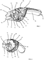
- the Figure 4 shows the suction device 2 according to the invention again Figure 3 with separation chamber 18, but in the present case with uncut cover element 94.
- Screw openings 96 can be seen via which the cup-shaped delimiting element 92 is connected to an intermediate element 23 for the suction unit 10 designed as a component carrier.
- the cup-shaped delimiting element 92 of the separation area has openings corresponding to the screw openings 96, via which the cup-shaped delimiting element 92 is connected to the cover element 94, the intermediate element 23, the second housing part designed as a cover element 27 and the grip shell 70.
- a sealing element 58 in the form of a sealing ring is injection molded onto the cover element 94, which in the assembled state interacts with a sealing groove 59 provided on the cup-shaped delimiting element 92 and seals the two components against the escape of liquid.
- the side view of the suction device 2 from the previous figures with a sectioned suction and separation area shows Figure 5 .
- the upper housing shell 64, the closure 42 and the suction nozzle 4 which can be plugged into the beak-shaped receptacle 62 are not shown.
- the suction channel 3 extends into the separation chamber 18.
- the separation chamber 18 is formed by the cup-shaped delimiting element 92 and the cover element 94, the cup-shaped delimiting element 92 as the first housing part of the multi-part housing forming part of the housing of the suction device 6.
- the suction channel 3 extends at least partially into the separation chamber 18.
- the suction channel 3 has two clamping lugs which extend into the separation chamber 18.
- a suction material guide element 14 is clamped onto the suction duct 3 as a separate part via the clamping lugs of the suction duct 3 and initially has an opening area which forms an extension of the suction duct 3.
- the suction material guide element 14 has a ramp-shaped shape and bends after the mouth area in the direction of the inlet opening 36 of the suction material guide. Due to the design, the suction material is guided in a direction that deviates from the suction material flow because of its inertia and the force of gravity acting on the suction material.
- a reaching-in guard 21 is arranged within the suction material guide element 14.
- the plate-shaped cover element 94 has a conical inlet connection 20 on the side facing the suction nozzle 4.
- FIG. 6 A perspective view of parts of the suction device 2 from the previous figures shows Figure 6 .
- the suction material container 8 is largely arranged in the handle 48.
- One wall of the suction material container 8 forms the grip shell 70, which forms the lower part of the housing 6, and towards the top the cover element (not shown), which is connected to the grip shell 70 in a sealing manner against the escape of suction material.
- a further wall of the suction material container 8 forms a shell component 32 inserted into the handle shell 70.
- the shell component 32 is a separate component and is connected to the handle shell 70 via a clamp connection.
- retaining lugs 38 are provided in the region of an inlet opening 36, symmetrically spaced from the longitudinal axis of the suction device 2, on the shell component 32, which lugs have correspondingly designed retaining projections 39 interact in a clamping manner on the grip shell 70.
- a retaining projection 39 is provided which, for the clamping connection, interacts with a corresponding retaining lug 38 which is integrally connected to the grip shell 70.
- the inlet opening 36 is provided in the suction material guide 30.
- the suction material separated in the separating device is passed through the inlet opening 36 into the suction material guide 30 and from there into the suction material container 8.
- the suction material container 8 can then be emptied by opening the closure 42.
- the suction material guide 30 is constructed in several parts.
- the geometrical delimitation of the suction material guide 30 is effected by the shell component 32 and, on the other hand, by areas of the grip shell 70.
- the third housing part not only forms part of the suction material container 8, but also forms part of the geometrical delimitation of the suction material guide 30.
- Shell component 32 is a separate component which is connected to the handle shell 70. Sealing means or sealing elements 58 are provided between the area of the shell component 32 and the area of the handle 70, which each form the geometric delimitation of the suction material guide 30, which prevent suction material from escaping from the suction material guide outside the inlets and outlets 36, 34.
- the sealing elements 58 are designed as a circumferential seal which is molded onto the shell component. Corresponding to the molded seal on the shell component 32, a corresponding sealing groove is provided in the handle shell 70. Alternatively, a second shell component can also be used in order to form the suction material guide together with the shell component 32.
- the advantage of this construction is that complex geometries can also be mapped, since in particular the handle shell 70 and the shell component 32 can be manufactured as a half-shell and in particular cavities and undercuts in the suction material guide 30 can be implemented in terms of production and assembly due to the multi-part construction of the suction material guide 30 . Furthermore, it is also easily possible to provide cutouts 82 in the shell component 30.
- an opening is formed in the handle shell 70 through which cabling for a charging connection of a das Suction unit comprehensive accumulator is carried out.
- the charging connection cannot be arranged directly visible to the user on the underside of the device 2 in the handle shell 70.
- the shell component 32 can be arranged through a recess 82 surrounding the opening in the handle shell 70.
- a positioning receptacle 80 in which a part of the upper cover element, not shown, can be arranged in a supporting and / or centering manner.
- Figure 7 shows the second housing part designed as a cover element 27 with a receiving area 22 in a view obliquely from the front.
- the receiving area 22, which is designed as a hollow body, has a rectangular cross section with a rounded top and bottom on the side of the receiving area 22 facing the suction nozzle 4.
- the rectangular cross section is provided to accommodate the electric motor 24, the accumulator 26 and the circuit board 25 together with their respective holders.
- the geometrically longer pocket for the accumulator 26 is provided in the part of the receiving area 22 directed towards the upper side of the suction device 2, whereby this is essentially round in cross section, corresponding to the cross section of the accumulator 26.
- a seat for a motor shaft bearing 87 of the electric motor 24 is provided in the part of the receiving area 22 that receives the electric motor 24, a seat for a motor shaft bearing 87 of the electric motor 24 is provided.
- This receptacle for the motor shaft bearing 87 is arranged concentrically with the electric motor 24 and with the fan wheel 11 driven by the latter.
- a positioning recess 89 is provided immediately next to the receptacle for the motor shaft bearing 87. This engages in a positioning receptacle 80 in a shell component 32, which is arranged below the receiving area 22 and forms part of the suction material guide 30, and ensures correct positioning of the shell component 32.
- a cable opening 88 is provided in the direction of the suction material guide 30, through which the cables for a charging connection on the underside of the suction device 2 when the suction device 2 is installed.
- a sealing element is located on the underside of the receiving area 22 provided, which seals the cable opening 88 in the receiving area 22 against entry of suction material.
- the sealing element is designed as a circumferential seal and interacts with a corresponding sealing groove on the shell component 32.
- the cover element 27 On the top of the cover element 27, in the part of the receiving area 22 facing the suction nozzle 4, a part of the cover element 27, which is arranged above the actuating button 68 on the circuit board 25 when the suction device 2 is installed, is formed as an elastic housing area 69.
- the actuating button 68 can be actuated in the assembled state through the elastic housing area 69 to switch the suction device 2 on and off.
- the elastic housing area 69 is formed from a soft material, in particular a rubber-like material.
- a recess is provided in the cover element 27, which is overmolded with a soft plastic forming the soft material.
- the overmolded area can extend beyond the elastic housing area 69 and forms an elevation 67 on the cover element 27.
- the upper housing shell 64 has, as in FIG Figure 2 shown, a recess corresponding to the overmolded area.
- the recess interacts with the elevation through the overmolded area 67 and thus facilitates the assembly of the upper housing shell 64, the overmolded area 67 preferably flush with the outer surface of the upper housing shell 64, possibly leaving a gap.
- part of the elastic housing area 69 is designed to be translucent. Furthermore, an LED is provided below the translucent area of the housing, preferably on the circuit board, which indicates an operating state of the suction device 2.
- the grip shell 70 forms the bulbous part of the suction device 2 up to the end of the receiving area 22 pointing towards the closure 42, and from there it merges into the handle 48. In this way, a particularly advantageous use of the installation space is achieved.
- FIG Figure 8 A perspective front and rear view of the intermediate element 23 designed as a component carrier is shown in FIG Figure 8 .
- the intermediate element 23 has four centering openings 29 which are arranged symmetrically distributed over the intermediate element 23.
- the upper part of the intermediate element 23 has a half-shell reinforced by ribs, which extends in the direction of the rotary separator 16.
- the height of the half-shell is designed in such a way that it lies above the height of the radially outer region of the fan blades of the fan wheel 11. In the embodiment shown, the half-shell extends between two centering openings, the upper two. In this way, better support between the centering or positioning elements 90 of the cover element 27 and the centering openings 29 of the intermediate element 23 is achieved.
- the provision of the half-shell serves to discharge the exhaust air flow in a directed manner out of the suction device 2, in particular via the sides of the suction device 2.
- a cover element designed as a plate-shaped delimitation element of the separation area is placed on the intermediate element 23 in the direction of the rotary separator and closes the area of the half-shell.
- the lower two centering openings 29 of the intermediate element 23 are positioned in the assembled state of the device on both sides of the semicircular inlet opening 36 in the suction material guide 30.
- the cover element 94 is sealingly placed on the inlet opening 36 in the suction material guide 30. Due to the laterally open areas formed between the intermediate element 23 and the cover element 94, the exhaust air flow is guided out of the suction device 2 through the ventilation slots 66 in the upper housing cover 64.
- a sealing element 58 designed as a circumferential seal is provided, the sealing element 58 being rectangular, corresponding to the rectangular opening of the receiving area 22, such that the intermediate element 23 seals the receiving area 22 against the ingress of suction material able.
- the seal is molded onto the intermediate element 23 and forms a flat sealing contour.
- the component receiving elements 28, in which the electric motor 24, the accumulator 26 and the circuit board 25 are held, are provided spatially within the circumferential seal on the intermediate element 23.
- the component receiving elements 28 are integrally connected to the intermediate element 23.
- the component receiving elements 28 do not completely enclose the electronic components in order to enable good heat dissipation, but also good support for the components.
- the circuit board comprises the actuation button 68 for switching the suction device 2 on and off as well as the LED, which indicates the operation of the suction device 2.
- a housing of the electric motor 24 has a rectangular cross section.
- the component receiving element 28 holding the electric motor 24 holds the electric motor 24 only on the housing covers, the part of the housing of the electric motor 24 facing away from the intermediate element 23 being covered less by the component receiving element 28 than the part facing the intermediate element 23.
- the temperature-sensitive accumulator 26 in particular is at least partially shielded from the waste heat from the electric motor 24.
- a complete, more solid enclosure of the electric motor 24 by the component receiving element 28 can be dispensed with, since the electric motor 24 is mounted for low-vibration operation of the fan wheel 11 via the motor shaft bearing 86, which is received in the receptacle for the motor shaft bearing 87 in the receiving area 22.
- inserted soft elements are provided which are set up in such a way that a secure fit of the electronic components, in particular of the electric motor 24 and the accumulator 26, is achieved. Furthermore, soft elements are also provided on the outside of the component receiving elements 28 in order to also hold the component receiving elements 28 securely in the receiving area 22.
- FIG. 9 A more detailed section of the suction and separation area is shown in Figure 9 in a sectional view.
- the recording of the suction material guide element 14 in the suction channel 3 is shown, which is inserted into the first housing part.
- the cup-shaped delimiting element 92 and the cover element 94 placed on the fan wheel 11 are shown assembled and form the separation chamber 18. Furthermore, the intermediate element 23 is also connected to the cup-shaped delimiting element 92 and the cover element 94 in the illustration.
- the second housing part designed as a cover element 27 is connected to the third housing part designed as a grip shell 70 via a clamp and screw connection.
- the intermediate element 23 and the cover element 94 are the intermediate element 23 and the cover element 94, as in FIG Figure 3 shown, postponed.
- the first housing part is placed on the cover element 94 and screwed to it, the centering and positioning elements of the cover element 27 and the grip shell 70 having threads.
- the upper housing shell 64 is pushed from the side of the suction nozzle 4 over the remaining housing parts and covers the connection area of the first housing part with the cover element 94, the intermediate element 23, and the cover element 27 and the handle shell 70 Increase in the overmolded area 67 be kept.
- the upper housing shell is braced and fastened by abutment against the lower handle shell 70 and the soft material applied to it and a screw connection on the side of the opening of the suction material container 8 below the closure 42. In this way, no connection point on the device is visible to the outside.
- the assembled suction device 2 without suction nozzle shows in a perspective view Figure 10 .
Landscapes
- Engineering & Computer Science (AREA)
- Mechanical Engineering (AREA)
- External Artificial Organs (AREA)
- Hooks, Suction Cups, And Attachment By Adhesive Means (AREA)
Claims (15)
- Aspirateur portatif (2) avec un canal d'aspiration (3) débouchant dans une buse d'aspiration (4) et avec un boîtier (6), une poignée, un récipient de matériau d'aspiration (8), avec une ouverture et une unité d'aspiration (10) pour générer un flux d'aspiration qui fournit une dépression appliquée à la buse d'aspiration (4), avec un dispositif de séparation (12), qui est capable de séparer le flux d'aspiration aspiré par l'intermédiaire de la buse d'aspiration (4) en un flux d'air d'échappement s'écoulant hors du dispositif d'aspiration (2) et en un matériau d'aspiration sous la forme de particules et/ou de constituants de fluide, les particules ou les constituants de fluide séparés étant collectés dans le récipient de matériau d'aspiration (2) et le récipient de matériau d'aspiration (8) pouvant être vidé par ouverture, caractérisé en ce que
le boîtier (6) est formé en plusieurs parties avec une première partie de boîtier, une deuxième partie de boîtier et une troisième partie de boîtier, une zone d'aspiration et de séparation recevant le dispositif de séparation (12) étant reçue et/ou formée par la première partie de boîtier et la deuxième partie de boîtier est reliée à la troisième partie de boîtier et le récipient de matériau d'aspiration (8) est disposé entre la deuxième partie de boîtier et la troisième partie de boîtier et/ou est formé par la deuxième partie de boîtier et la troisième partie de boîtier, et dans lequel les zones de connexion de la première partie de boîtier, de la deuxième partie de boîtier et de la troisième partie de boîtier sont recou-vertes par une partie de boîtier de couverture. - Aspirateur portatif (2) selon la revendication 1, caractérisé en ce que la partie de boîtier de recouvrement entoure les parties de boîtier au moins par sections à la manière d'un manchon enfiché.
- Aspirateur portatif (2) selon l'une des revendications précédentes, caractérisé en ce que le récipient de matériau d'aspiration (8) est solidement intégré dans l'aspirateur (2), en particulier est formé par le boîtier (6) de l'aspirateur (2), de préférence par la deuxième partie de boîtier et la troisième partie de boîtier.
- Aspirateur portatif (2) selon l'une des revendications précédentes, caractérisé en ce qu'une partie d'extrémité du dispositif d'aspiration (2) opposée à la buse d'aspiration (4) est formée par la poignée.
- Aspirateur portatif (2) selon l'une des revendications précédentes, caractérisé en ce que le récipient de matériau d'aspiration (8) est disposé au moins partiellement dans la poignée du dispositif d'aspiration (2).
- Aspirateur portatif (2) selon l'une des revendications précédentes, caractérisé en ce que la poignée est formée en plusieurs parties, des sections de la deuxième partie de boîtier et de la troisième partie de boîtier formant au moins une zone partielle de la poignée.
- Aspirateur portatif (2) selon l'une des revendications précédentes, caractérisée en ce que l'unité d'aspiration comprend au moins un moteur électrique et un accumulateur, et le moteur électrique et l'accumulateur sont disposés entre la deuxième partie de boîtier et la troisième partie de boîtier.
- Aspirateur portatif (2) selon l'une des revendications précédentes, caractérisé en ce que le moteur électrique et l'accumulateur sont disposés à l'intérieur d'un espace fermé qui est au moins partiellement entouré par le récipient de matériau d'aspiration (8) et qui forme un espace de réception, la deuxième partie du boîtier constituant en particulier la zone de réception et la zone de réception faisant en particulier partie de la limite du récipient de matière d'aspiration.
- Aspirateur portatif (2) selon l'une des revendications précédentes, caractérisé en ce qu'une roue de ventilateur de l'unité d'aspiration est disposée entre la première partie de boîtier, qui reçoit la zone d'aspiration et de séparation, et les parties de boîtier, qui reçoivent le récipient de matériau d'aspiration.
- Aspirateur portatif (2) selon l'une des revendications précédentes, caractérisé en ce qu'une fermeture (42) est prévue pour fermer l'ouverture du récipient d'aspiration (8), la fermeture (42) formant l'extrémité distale de la poignée et notamment une zone de stationnement.
- Aspirateur portatif (2) selon l'une des revendications précédentes, caractérisé en ce que le dispositif d'aspiration comprend deux zones de dépôt qui sont disposées et réglées de telle sorte que la buse d'aspiration (4) est espacée de la surface de dépôt plane (72) lorsque le dispositif d'aspiration (2) est déposé de manière conforme sur une surface de dépôt plane (72), les zones de dépôt étant formées en particulier d'un matériau mou.
- Aspirateur portatif (2) selon l'une des revendications précédentes, caractérisé en ce que dans la partie du dispositif d'aspiration (2) tournée vers la buse d'aspiration (4), sont prévus deux supports qui forment la deuxième zone de dépôt, les supports étant formés notamment d'un caoutchouc souple.
- Aspirateur portatif (2) selon l'une des revendications précédentes, caractérisé en ce que la troisième partie de boîtier forme une face inférieure de boîtier et un matériau souple est prévu au moins partiellement sur la surface de la troisième partie de boîtier, lequel matériau souple est choisi en épaisseur et en matière de telle sorte que le dispositif d'aspiration (2) et les surfaces environnantes sont protégés contre les chocs lorsqu'ils sont en contact avec le dispositif d'aspiration (2).
- Aspirateur portatif (2) selon l'une des revendications précédentes, caractérisé en ce qu'une carte de circuit imprimé avec un bouton d'actionnement est disposée à l'intérieur du boîtier et une zone de boîtier élastique est disposée au-dessus du bouton d'actionnement, au moyen de laquelle le bouton d'actionnement peut être actionné, la zone de boîtier élastique étant de préférence appliquée sur le boîtier par moulage par injection à 2 composants.
- Aspirateur portatif (2) selon la revendication précédente, caractérisé en ce qu'un moyen d'éclairage pour indiquer le fonctionnement du dispositif d'aspiration, en particulier une DEL, est disposé sur la carte de circuit imprimé et une zone transparente est formée dans la zone de logement élastique, qui est disposée pour indiquer un fonctionnement du dispositif d'aspiration par le moyen d'éclairage.
Priority Applications (1)
| Application Number | Priority Date | Filing Date | Title |
|---|---|---|---|
| EP19186102.0A EP3763267B1 (fr) | 2019-07-12 | 2019-07-12 | Aspirateur portatif |
Applications Claiming Priority (1)
| Application Number | Priority Date | Filing Date | Title |
|---|---|---|---|
| EP19186102.0A EP3763267B1 (fr) | 2019-07-12 | 2019-07-12 | Aspirateur portatif |
Publications (2)
| Publication Number | Publication Date |
|---|---|
| EP3763267A1 EP3763267A1 (fr) | 2021-01-13 |
| EP3763267B1 true EP3763267B1 (fr) | 2021-09-01 |
Family
ID=67262203
Family Applications (1)
| Application Number | Title | Priority Date | Filing Date |
|---|---|---|---|
| EP19186102.0A Active EP3763267B1 (fr) | 2019-07-12 | 2019-07-12 | Aspirateur portatif |
Country Status (1)
| Country | Link |
|---|---|
| EP (1) | EP3763267B1 (fr) |
Families Citing this family (1)
| Publication number | Priority date | Publication date | Assignee | Title |
|---|---|---|---|---|
| WO2025140061A1 (fr) * | 2023-12-30 | 2025-07-03 | 苏州简单有为科技有限公司 | Dispositif de nettoyage de surface et système de nettoyage |
Family Cites Families (7)
| Publication number | Priority date | Publication date | Assignee | Title |
|---|---|---|---|---|
| US4542557A (en) * | 1984-03-07 | 1985-09-24 | Cic Int'l. Corp. | Wet-dry vacuum cleaner |
| US6968593B1 (en) * | 2001-08-14 | 2005-11-29 | Bissell Homecare, Inc. | Hand-held deep cleaner |
| WO2014182201A1 (fr) * | 2013-05-07 | 2014-11-13 | Aktiebolaget Electrolux | Aspirateur |
| WO2015007325A1 (fr) | 2013-07-18 | 2015-01-22 | Alfred Kärcher Gmbh & Co. Kg | Appareil de nettoyage de surfaces dures portable |
| DE202013104011U1 (de) | 2013-09-05 | 2013-09-18 | Leifheit Ag | Tragbares Sauggerät für Flüssigkeiten oder Flüssigkeits-/Luftgemische |
| EP3323332B1 (fr) * | 2016-11-16 | 2019-06-26 | Black & Decker Inc. | Dispositif de nettoyage |
| CN108634866B (zh) * | 2018-06-04 | 2024-12-20 | 苏州欧圣电气股份有限公司 | 手持便携式吸尘器 |
-
2019
- 2019-07-12 EP EP19186102.0A patent/EP3763267B1/fr active Active
Also Published As
| Publication number | Publication date |
|---|---|
| EP3763267A1 (fr) | 2021-01-13 |
Similar Documents
| Publication | Publication Date | Title |
|---|---|---|
| EP3393319B1 (fr) | Buse d'aspiration pour un appareil de nettoyage de surface dures et appareil de nettoyage de surfaces dures comportant une telle buse d'aspiration | |
| EP2230980B1 (fr) | Dispositif d'aspiration de surfaces dures | |
| EP3021727B1 (fr) | Appareil de nettoyage de surfaces dures portable | |
| DE3220644A1 (de) | Absaugeinrichtung | |
| DE202012012814U1 (de) | Flüssigkeitssaugvorrichtung zum Abziehen und Aufsaugen von Flüssigkeiten | |
| EP3021723B2 (fr) | Appareil de nettoyage de surfaces dures portable | |
| EP3081130A1 (fr) | Appareil d'aspiration pour surfaces dures | |
| EP3681360B1 (fr) | Appareil de nettoyage des surfaces | |
| WO2000076386A1 (fr) | Aspirateur | |
| EP3393320B1 (fr) | Buse d'aspiration pour appareil de nettoyage de surface dure et appareil de nettoyage de surface dure équipé d'une telle buse | |
| EP3763265B1 (fr) | Aspirateur portatif | |
| CH685327A5 (de) | Anschlussvorrichtung zum Anschliessen eines Gebläses an ein Schutzmaskenfilter. | |
| EP3763267B1 (fr) | Aspirateur portatif | |
| EP3681361B1 (fr) | Appareil de nettoyage de surfaces | |
| EP3393322B1 (fr) | Appareil portable de nettoyage de surfaces dures | |
| DE202019103861U1 (de) | Tragbares Sauggerät | |
| EP3058893B1 (fr) | Dispositif d'aspiration | |
| EP3763264B1 (fr) | Aspirateur portatif | |
| EP3763263B1 (fr) | Aspirateur portatif | |
| DE202019103942U1 (de) | Staubsauger | |
| EP2992799B1 (fr) | Appareil d'aspiration portatif doté d'une buse d'aspiration interchangeable | |
| EP3763266B1 (fr) | Aspirateur portatif | |
| DE19736596A1 (de) | Kleinstaubsauger mit Zusatzrohr | |
| DE102015102239B4 (de) | Dentallaborabsaugvorrichtung | |
| DE8902928U1 (de) | Stichsäge mit Absaugkanal |
Legal Events
| Date | Code | Title | Description |
|---|---|---|---|
| PUAI | Public reference made under article 153(3) epc to a published international application that has entered the european phase |
Free format text: ORIGINAL CODE: 0009012 |
|
| STAA | Information on the status of an ep patent application or granted ep patent |
Free format text: STATUS: REQUEST FOR EXAMINATION WAS MADE |
|
| 17P | Request for examination filed |
Effective date: 20200221 |
|
| AK | Designated contracting states |
Kind code of ref document: A1 Designated state(s): AL AT BE BG CH CY CZ DE DK EE ES FI FR GB GR HR HU IE IS IT LI LT LU LV MC MK MT NL NO PL PT RO RS SE SI SK SM TR |
|
| AX | Request for extension of the european patent |
Extension state: BA ME |
|
| GRAP | Despatch of communication of intention to grant a patent |
Free format text: ORIGINAL CODE: EPIDOSNIGR1 |
|
| STAA | Information on the status of an ep patent application or granted ep patent |
Free format text: STATUS: GRANT OF PATENT IS INTENDED |
|
| RIC1 | Information provided on ipc code assigned before grant |
Ipc: A47L 5/24 20060101ALI20210429BHEP Ipc: A47L 9/22 20060101ALI20210429BHEP Ipc: A47L 9/28 20060101ALI20210429BHEP Ipc: A47L 9/00 20060101ALI20210429BHEP Ipc: A47L 7/00 20060101ALI20210429BHEP Ipc: A47L 1/05 20060101AFI20210429BHEP |
|
| INTG | Intention to grant announced |
Effective date: 20210519 |
|
| GRAS | Grant fee paid |
Free format text: ORIGINAL CODE: EPIDOSNIGR3 |
|
| GRAA | (expected) grant |
Free format text: ORIGINAL CODE: 0009210 |
|
| STAA | Information on the status of an ep patent application or granted ep patent |
Free format text: STATUS: THE PATENT HAS BEEN GRANTED |
|
| AK | Designated contracting states |
Kind code of ref document: B1 Designated state(s): AL AT BE BG CH CY CZ DE DK EE ES FI FR GB GR HR HU IE IS IT LI LT LU LV MC MK MT NL NO PL PT RO RS SE SI SK SM TR |
|
| REG | Reference to a national code |
Ref country code: GB Ref legal event code: FG4D Free format text: NOT ENGLISH |
|
| REG | Reference to a national code |
Ref country code: CH Ref legal event code: EP Ref country code: AT Ref legal event code: REF Ref document number: 1425305 Country of ref document: AT Kind code of ref document: T Effective date: 20210915 |
|
| REG | Reference to a national code |
Ref country code: DE Ref legal event code: R096 Ref document number: 502019002185 Country of ref document: DE |
|
| REG | Reference to a national code |
Ref country code: IE Ref legal event code: FG4D Free format text: LANGUAGE OF EP DOCUMENT: GERMAN |
|
| REG | Reference to a national code |
Ref country code: LT Ref legal event code: MG9D |
|
| REG | Reference to a national code |
Ref country code: NL Ref legal event code: MP Effective date: 20210901 |
|
| PG25 | Lapsed in a contracting state [announced via postgrant information from national office to epo] |
Ref country code: LT Free format text: LAPSE BECAUSE OF FAILURE TO SUBMIT A TRANSLATION OF THE DESCRIPTION OR TO PAY THE FEE WITHIN THE PRESCRIBED TIME-LIMIT Effective date: 20210901 Ref country code: BG Free format text: LAPSE BECAUSE OF FAILURE TO SUBMIT A TRANSLATION OF THE DESCRIPTION OR TO PAY THE FEE WITHIN THE PRESCRIBED TIME-LIMIT Effective date: 20211201 Ref country code: HR Free format text: LAPSE BECAUSE OF FAILURE TO SUBMIT A TRANSLATION OF THE DESCRIPTION OR TO PAY THE FEE WITHIN THE PRESCRIBED TIME-LIMIT Effective date: 20210901 Ref country code: NO Free format text: LAPSE BECAUSE OF FAILURE TO SUBMIT A TRANSLATION OF THE DESCRIPTION OR TO PAY THE FEE WITHIN THE PRESCRIBED TIME-LIMIT Effective date: 20211201 Ref country code: ES Free format text: LAPSE BECAUSE OF FAILURE TO SUBMIT A TRANSLATION OF THE DESCRIPTION OR TO PAY THE FEE WITHIN THE PRESCRIBED TIME-LIMIT Effective date: 20210901 Ref country code: FI Free format text: LAPSE BECAUSE OF FAILURE TO SUBMIT A TRANSLATION OF THE DESCRIPTION OR TO PAY THE FEE WITHIN THE PRESCRIBED TIME-LIMIT Effective date: 20210901 Ref country code: SE Free format text: LAPSE BECAUSE OF FAILURE TO SUBMIT A TRANSLATION OF THE DESCRIPTION OR TO PAY THE FEE WITHIN THE PRESCRIBED TIME-LIMIT Effective date: 20210901 Ref country code: RS Free format text: LAPSE BECAUSE OF FAILURE TO SUBMIT A TRANSLATION OF THE DESCRIPTION OR TO PAY THE FEE WITHIN THE PRESCRIBED TIME-LIMIT Effective date: 20210901 |
|
| PG25 | Lapsed in a contracting state [announced via postgrant information from national office to epo] |
Ref country code: PL Free format text: LAPSE BECAUSE OF FAILURE TO SUBMIT A TRANSLATION OF THE DESCRIPTION OR TO PAY THE FEE WITHIN THE PRESCRIBED TIME-LIMIT Effective date: 20210901 Ref country code: LV Free format text: LAPSE BECAUSE OF FAILURE TO SUBMIT A TRANSLATION OF THE DESCRIPTION OR TO PAY THE FEE WITHIN THE PRESCRIBED TIME-LIMIT Effective date: 20210901 Ref country code: GR Free format text: LAPSE BECAUSE OF FAILURE TO SUBMIT A TRANSLATION OF THE DESCRIPTION OR TO PAY THE FEE WITHIN THE PRESCRIBED TIME-LIMIT Effective date: 20211202 |
|
| PG25 | Lapsed in a contracting state [announced via postgrant information from national office to epo] |
Ref country code: IS Free format text: LAPSE BECAUSE OF FAILURE TO SUBMIT A TRANSLATION OF THE DESCRIPTION OR TO PAY THE FEE WITHIN THE PRESCRIBED TIME-LIMIT Effective date: 20220101 Ref country code: SM Free format text: LAPSE BECAUSE OF FAILURE TO SUBMIT A TRANSLATION OF THE DESCRIPTION OR TO PAY THE FEE WITHIN THE PRESCRIBED TIME-LIMIT Effective date: 20210901 Ref country code: SK Free format text: LAPSE BECAUSE OF FAILURE TO SUBMIT A TRANSLATION OF THE DESCRIPTION OR TO PAY THE FEE WITHIN THE PRESCRIBED TIME-LIMIT Effective date: 20210901 Ref country code: RO Free format text: LAPSE BECAUSE OF FAILURE TO SUBMIT A TRANSLATION OF THE DESCRIPTION OR TO PAY THE FEE WITHIN THE PRESCRIBED TIME-LIMIT Effective date: 20210901 Ref country code: PT Free format text: LAPSE BECAUSE OF FAILURE TO SUBMIT A TRANSLATION OF THE DESCRIPTION OR TO PAY THE FEE WITHIN THE PRESCRIBED TIME-LIMIT Effective date: 20220103 Ref country code: NL Free format text: LAPSE BECAUSE OF FAILURE TO SUBMIT A TRANSLATION OF THE DESCRIPTION OR TO PAY THE FEE WITHIN THE PRESCRIBED TIME-LIMIT Effective date: 20210901 Ref country code: EE Free format text: LAPSE BECAUSE OF FAILURE TO SUBMIT A TRANSLATION OF THE DESCRIPTION OR TO PAY THE FEE WITHIN THE PRESCRIBED TIME-LIMIT Effective date: 20210901 Ref country code: AL Free format text: LAPSE BECAUSE OF FAILURE TO SUBMIT A TRANSLATION OF THE DESCRIPTION OR TO PAY THE FEE WITHIN THE PRESCRIBED TIME-LIMIT Effective date: 20210901 |
|
| REG | Reference to a national code |
Ref country code: DE Ref legal event code: R097 Ref document number: 502019002185 Country of ref document: DE |
|
| PLBE | No opposition filed within time limit |
Free format text: ORIGINAL CODE: 0009261 |
|
| STAA | Information on the status of an ep patent application or granted ep patent |
Free format text: STATUS: NO OPPOSITION FILED WITHIN TIME LIMIT |
|
| PG25 | Lapsed in a contracting state [announced via postgrant information from national office to epo] |
Ref country code: IT Free format text: LAPSE BECAUSE OF FAILURE TO SUBMIT A TRANSLATION OF THE DESCRIPTION OR TO PAY THE FEE WITHIN THE PRESCRIBED TIME-LIMIT Effective date: 20210901 Ref country code: DK Free format text: LAPSE BECAUSE OF FAILURE TO SUBMIT A TRANSLATION OF THE DESCRIPTION OR TO PAY THE FEE WITHIN THE PRESCRIBED TIME-LIMIT Effective date: 20210901 |
|
| 26N | No opposition filed |
Effective date: 20220602 |
|
| PG25 | Lapsed in a contracting state [announced via postgrant information from national office to epo] |
Ref country code: MC Free format text: LAPSE BECAUSE OF FAILURE TO SUBMIT A TRANSLATION OF THE DESCRIPTION OR TO PAY THE FEE WITHIN THE PRESCRIBED TIME-LIMIT Effective date: 20210901 |
|
| REG | Reference to a national code |
Ref country code: CH Ref legal event code: PL |
|
| REG | Reference to a national code |
Ref country code: BE Ref legal event code: MM Effective date: 20220731 |
|
| PG25 | Lapsed in a contracting state [announced via postgrant information from national office to epo] |
Ref country code: LU Free format text: LAPSE BECAUSE OF NON-PAYMENT OF DUE FEES Effective date: 20220712 Ref country code: LI Free format text: LAPSE BECAUSE OF NON-PAYMENT OF DUE FEES Effective date: 20220731 Ref country code: FR Free format text: LAPSE BECAUSE OF NON-PAYMENT OF DUE FEES Effective date: 20220731 Ref country code: CH Free format text: LAPSE BECAUSE OF NON-PAYMENT OF DUE FEES Effective date: 20220731 |
|
| PG25 | Lapsed in a contracting state [announced via postgrant information from national office to epo] |
Ref country code: BE Free format text: LAPSE BECAUSE OF NON-PAYMENT OF DUE FEES Effective date: 20220731 |
|
| PG25 | Lapsed in a contracting state [announced via postgrant information from national office to epo] |
Ref country code: IE Free format text: LAPSE BECAUSE OF NON-PAYMENT OF DUE FEES Effective date: 20220712 |
|
| GBPC | Gb: european patent ceased through non-payment of renewal fee |
Effective date: 20230712 |
|
| PG25 | Lapsed in a contracting state [announced via postgrant information from national office to epo] |
Ref country code: MK Free format text: LAPSE BECAUSE OF FAILURE TO SUBMIT A TRANSLATION OF THE DESCRIPTION OR TO PAY THE FEE WITHIN THE PRESCRIBED TIME-LIMIT Effective date: 20210901 Ref country code: CY Free format text: LAPSE BECAUSE OF FAILURE TO SUBMIT A TRANSLATION OF THE DESCRIPTION OR TO PAY THE FEE WITHIN THE PRESCRIBED TIME-LIMIT Effective date: 20210901 Ref country code: GB Free format text: LAPSE BECAUSE OF NON-PAYMENT OF DUE FEES Effective date: 20230712 |
|
| PG25 | Lapsed in a contracting state [announced via postgrant information from national office to epo] |
Ref country code: HU Free format text: LAPSE BECAUSE OF FAILURE TO SUBMIT A TRANSLATION OF THE DESCRIPTION OR TO PAY THE FEE WITHIN THE PRESCRIBED TIME-LIMIT; INVALID AB INITIO Effective date: 20190712 |
|
| PG25 | Lapsed in a contracting state [announced via postgrant information from national office to epo] |
Ref country code: TR Free format text: LAPSE BECAUSE OF FAILURE TO SUBMIT A TRANSLATION OF THE DESCRIPTION OR TO PAY THE FEE WITHIN THE PRESCRIBED TIME-LIMIT Effective date: 20210901 |
|
| PG25 | Lapsed in a contracting state [announced via postgrant information from national office to epo] |
Ref country code: MT Free format text: LAPSE BECAUSE OF FAILURE TO SUBMIT A TRANSLATION OF THE DESCRIPTION OR TO PAY THE FEE WITHIN THE PRESCRIBED TIME-LIMIT Effective date: 20210901 |
|
| REG | Reference to a national code |
Ref country code: DE Ref legal event code: R082 Ref document number: 502019002185 Country of ref document: DE Representative=s name: KBN IP PATENTANWAELTE PARTNERSCHAFT MBB, DE |
|
| PGFP | Annual fee paid to national office [announced via postgrant information from national office to epo] |
Ref country code: CZ Payment date: 20250619 Year of fee payment: 7 |
|
| REG | Reference to a national code |
Ref country code: AT Ref legal event code: MM01 Ref document number: 1425305 Country of ref document: AT Kind code of ref document: T Effective date: 20240712 |
|
| PGFP | Annual fee paid to national office [announced via postgrant information from national office to epo] |
Ref country code: DE Payment date: 20250723 Year of fee payment: 7 |
|
| PG25 | Lapsed in a contracting state [announced via postgrant information from national office to epo] |
Ref country code: AT Free format text: LAPSE BECAUSE OF NON-PAYMENT OF DUE FEES Effective date: 20240712 |
|
| PG25 | Lapsed in a contracting state [announced via postgrant information from national office to epo] |
Ref country code: SI Free format text: LAPSE BECAUSE OF FAILURE TO SUBMIT A TRANSLATION OF THE DESCRIPTION OR TO PAY THE FEE WITHIN THE PRESCRIBED TIME-LIMIT Effective date: 20210901 |
|
| PGFP | Annual fee paid to national office [announced via postgrant information from national office to epo] |
Ref country code: AT Payment date: 20260410 Year of fee payment: 5 |