EP3763267B1 - Tragbares sauggerät - Google Patents
Tragbares sauggerät Download PDFInfo
- Publication number
- EP3763267B1 EP3763267B1 EP19186102.0A EP19186102A EP3763267B1 EP 3763267 B1 EP3763267 B1 EP 3763267B1 EP 19186102 A EP19186102 A EP 19186102A EP 3763267 B1 EP3763267 B1 EP 3763267B1
- Authority
- EP
- European Patent Office
- Prior art keywords
- suction
- housing part
- vacuum cleaner
- housing
- suction material
- Prior art date
- Legal status (The legal status is an assumption and is not a legal conclusion. Google has not performed a legal analysis and makes no representation as to the accuracy of the status listed.)
- Active
Links
Images


Classifications
-
- A—HUMAN NECESSITIES
- A47—FURNITURE; DOMESTIC ARTICLES OR APPLIANCES; COFFEE MILLS; SPICE MILLS; SUCTION CLEANERS IN GENERAL
- A47L—DOMESTIC WASHING OR CLEANING; SUCTION CLEANERS IN GENERAL
- A47L1/00—Cleaning windows
- A47L1/02—Power-driven machines or devices
- A47L1/05—Hand apparatus with built-in electric motors
-
- A—HUMAN NECESSITIES
- A47—FURNITURE; DOMESTIC ARTICLES OR APPLIANCES; COFFEE MILLS; SPICE MILLS; SUCTION CLEANERS IN GENERAL
- A47L—DOMESTIC WASHING OR CLEANING; SUCTION CLEANERS IN GENERAL
- A47L5/00—Structural features of suction cleaners
- A47L5/12—Structural features of suction cleaners with power-driven air-pumps or air-compressors, e.g. driven by motor vehicle engine vacuum
- A47L5/22—Structural features of suction cleaners with power-driven air-pumps or air-compressors, e.g. driven by motor vehicle engine vacuum with rotary fans
- A47L5/24—Hand-supported suction cleaners
-
- A—HUMAN NECESSITIES
- A47—FURNITURE; DOMESTIC ARTICLES OR APPLIANCES; COFFEE MILLS; SPICE MILLS; SUCTION CLEANERS IN GENERAL
- A47L—DOMESTIC WASHING OR CLEANING; SUCTION CLEANERS IN GENERAL
- A47L7/00—Suction cleaners adapted for additional purposes; Tables with suction openings for cleaning purposes; Containers for cleaning articles by suction; Suction cleaners adapted to cleaning of brushes; Suction cleaners adapted to taking-up liquids
- A47L7/0004—Suction cleaners adapted to take up liquids, e.g. wet or dry vacuum cleaners
- A47L7/0019—Details of the casing
-
- A—HUMAN NECESSITIES
- A47—FURNITURE; DOMESTIC ARTICLES OR APPLIANCES; COFFEE MILLS; SPICE MILLS; SUCTION CLEANERS IN GENERAL
- A47L—DOMESTIC WASHING OR CLEANING; SUCTION CLEANERS IN GENERAL
- A47L9/00—Details or accessories of suction cleaners, e.g. mechanical means for controlling the suction or for effecting pulsating action; Storing devices specially adapted to suction cleaners or parts thereof; Carrying-vehicles specially adapted for suction cleaners
- A47L9/0009—Storing devices ; Supports, stands or holders
- A47L9/0054—Stands or the like for temporary interruption of work
-
- A—HUMAN NECESSITIES
- A47—FURNITURE; DOMESTIC ARTICLES OR APPLIANCES; COFFEE MILLS; SPICE MILLS; SUCTION CLEANERS IN GENERAL
- A47L—DOMESTIC WASHING OR CLEANING; SUCTION CLEANERS IN GENERAL
- A47L9/00—Details or accessories of suction cleaners, e.g. mechanical means for controlling the suction or for effecting pulsating action; Storing devices specially adapted to suction cleaners or parts thereof; Carrying-vehicles specially adapted for suction cleaners
- A47L9/22—Mountings for motor fan assemblies
-
- A—HUMAN NECESSITIES
- A47—FURNITURE; DOMESTIC ARTICLES OR APPLIANCES; COFFEE MILLS; SPICE MILLS; SUCTION CLEANERS IN GENERAL
- A47L—DOMESTIC WASHING OR CLEANING; SUCTION CLEANERS IN GENERAL
- A47L9/00—Details or accessories of suction cleaners, e.g. mechanical means for controlling the suction or for effecting pulsating action; Storing devices specially adapted to suction cleaners or parts thereof; Carrying-vehicles specially adapted for suction cleaners
- A47L9/28—Installation of the electric equipment, e.g. adaptation or attachment to the suction cleaner; Controlling suction cleaners by electric means
- A47L9/2857—User input or output elements for control, e.g. buttons, switches or displays
Definitions
- the invention relates to a portable suction device according to the preamble of claim 1.
- the invention relates to a portable suction device with a suction channel opening into a suction nozzle and with a housing, a handle, a suction material container with an opening, a closure closing the opening, and a suction unit for generating a suction flow, which provides a suction vacuum applied to the suction nozzle, with a separation device which is able to split the suction flow sucked in via the suction nozzle into an exhaust air flow flowing out of the suction device and into suction material in the form of particles and / or fluid components, the separated particles or fluid components are collected in the suction material container and the suction material container can be emptied by opening the closure.
- these devices also have a pull-off lip for pulling off liquids, the pull-off lip being arranged on the suction nozzle.
- these devices are usually battery-operated and are held in the hand of a user while the user guides the pull-off lip along the surface to be vacuumed.
- Portable devices of this type are among others from the EP 2 845 530 B1 known.
- the known suction devices are used to suck up a liquid / air mixture. As in the case of the device mentioned, this can be done for sucking up liquid, for example from a flat surface such as a table top, window panes or tiles.
- a pull-off lip arranged on the suction nozzle is provided in the generic devices for residue-free cleaning of the surfaces.
- the suction material is stored in a suction material container and must therefore be separated from the suction flow from the air flow.
- the known separation devices of the portable suction devices use baffle plates and air deflectors to separate the suction material from the suction flow.
- Suction devices designed in this way have disadvantages. Sharp air deflections and baffle plates cause pressure losses that have a negative impact on the efficiency of the suction device. For the user, this manifests itself in a shorter device running time for a given usable capacity of the accumulator. In addition, such devices are correspondingly larger.
- suction material Another requirement of the generic suction devices is to prevent the suction material from flowing back into the separation area.
- the suction material is first deposited in a separation area. The suction material is then transferred into the suction material container via a suction material guide.
- the outlet of the suction material guide is regularly positioned in the center of the suction material container. In this way, an evasive volume is created around the outlet of the suction material guide, in which the suction material already stored in the suction material container is temporarily stored when the device is pivoted.
- the suction devices In order to drain the suction material from the suction material container, the suction devices often have a closure designed as a small stopper on the suction material container. Furthermore, the suction material container is usually designed to be separately removable and also has a larger opening for better cleaning. The larger opening is also provided for reasons of assemblability, in order to enable the assembly of internal parts such as the suction material guide.
- the housing is constructed in several parts.
- the housing has a first housing part, of which the suction and separation area in which the separation device is arranged, is received and / or formed. Furthermore, a second housing part is connected to a third housing part and the suction material container is arranged between the second and third housing parts. Connection areas of the first housing part with the other housing parts and connection areas of the connection between the second and third housing parts are covered by a cover housing part. In particular, a connection area is provided in which the first, second and third housing parts are connected to one another.
- connection areas of the first housing part with an adjacent component and / or of the second housing part with the third housing part are completely covered by the cover housing part.
- the cover housing part preferably at least partially encloses the housing parts in the form of a sleeve.
- the shape of the suction device is designed in such a way that the suction device extends into the handle on the end section opposite the suction nozzle.
- the cover housing part is pushed over the housing parts from the side of the suction nozzle.
- the first housing part arranged on the side of the suction nozzle particularly preferably tapers conically in the direction of the suction channel.
- the cover housing part can be fastened by means of a clamp, snap-in and / or screw connection.
- a contact area is provided on at least one of the housing parts, preferably on the second or third housing part, against which the cover housing part can be pushed and fastened via a clamp and / or screw connection.
- the closure preferably forms the distal end of the handle, wherein the closure can be designed by means of a double-walled construction so that the shape of the suction device is continued over an outer contour of the closure.
- the closure is formed from at least a first closure element and a second closure element in such a way that the first closure element is designed to seal the opening of the suction material container against leakage of suction material and the second closure element is arranged outside the first closure element.
- the closure that is to say the first and second closure elements, is preferably designed in one piece.
- the second closure element is spaced apart from the first closure element.
- the second closure element can be arranged around the first closure element in the manner of a bell.
- the suction material container is advantageously permanently integrated in the suction device.
- the suction material container can also be formed by the housing of the suction device, particularly preferably by the second and third housing parts.
- the suction material container can be arranged at least partially in the handle of the suction device.
- the handle is designed in several parts and the second housing part and the third housing part form the handle.
- a suction material guide can be provided between the suction channel and the suction material container, through which the suction material enters the suction material container when the suction device is used as intended, the geometric delimitation of the suction material guide being formed in several parts and at least through a separate shell component is formed. In this way, a backflow of suction material back into the separation area or into a separation chamber is avoided when the device is pivoted.
- such a configuration has the advantage that by connecting two half-shells, a complicated, winding and angled construction of the suction material guide is possible, so that a desired suction device design can be formed and, in particular, the available installation space can also be fully utilized.
- the geometric delimitation of the suction material guide can be formed in part by a wall area of the suction material container.
- the wall area can also form part of the housing of the suction device, in particular of the third housing part.
- the suction material container and the suction material guide are at least partially arranged in the handle.
- An advantageous embodiment of the suction device according to the invention provides that the suction material guide is arranged at least partially, in particular completely, in the suction material container.
- the geometric delimitation of the suction material guide is particularly preferably partially formed by an area of the third housing part forming part of the handle. It has been found to be particularly advantageous for the assembly that the at least one separate shell component is detachably fastened, in particular clamped and / or screwed, within the housing, preferably fastened to the third housing part.
- a releasable connection for holding the shell component for example, clamping lugs and / or snap hooks can be provided on the housing and / or the shell component.
- the suction unit comprises at least one electric motor and an accumulator and a fan wheel which is driven by the electric motor.
- the electric motor and accumulator can be arranged between the second and third housing parts.
- the electric motor and the accumulator can be arranged inside the suction material container, the second housing part preferably providing a receiving area for the electric motor and accumulator and the receiving area forming part of the suction material container boundary.
- the fan wheel of the suction unit is arranged between the first housing part, which receives the suction and separation area, and the housing parts, which receive the suction material container.
- an intermediate element can preferably be provided between the first housing part with a rear housing area formed by the second housing part and the third housing part, to which on the one hand the first housing part and on the other hand the rear housing area is attached.
- a rotary separator which is part of the separating device and protrudes into the separating area, is preferably also provided on the fan wheel.
- a cover element is provided between the separation area and the fan wheel, through which the rotary separator protrudes into the separation area in the direction of the suction nozzle.
- a separation chamber can preferably be provided as the separation area. This is advantageously between the suction channel and suction material container arranged, wherein the separation chamber is delimited by the first housing part of the suction device and the cover element.
- the separation chamber at least one inlet opening for the suction flow through the suction channel and an exhaust air opening for the exhaust air flow and an outlet opening for the suction material are provided in the cover element.
- the exhaust air opening is preferably the opening in the cover element through which the rotary separator protrudes.
- a suction material guide element forms a first stage of separation for a compact design. In an advantageous embodiment, this can be aligned directly in the direction of the suction material container. A second stage of separation is formed by the rotary separator.
- the suction material container has an inlet opening indirectly via a suction material guide or directly.
- the cover element has a further opening corresponding to the inlet opening of the suction material container, the inlet opening being formed in particular indirectly via an inlet of a suction material guide.
- the further opening can be the aforementioned drainage opening from the separation chamber.
- a preferred embodiment of the invention of the portable suction device provides that part of the suction material container delimitation, preferably the second housing part, has a receiving area for receiving electronic components of the suction device, the receiving area being in the form of at least one cavity that is watertight except for the opening and is designed to be watertight closable by the separate intermediate element.
- the electronic components include at least the electric motor and the accumulator, but can also include further electronic components, such as monitoring and / or control elements arranged on a circuit board.
- the cavity can consist of one or more pockets, the individual electronic components being arranged in the pockets.
- the electronic components are protected against the ingress of dust and water through the watertight, sealed cavity in the suction cup delimitation protected. Furthermore, the arrangement does not have any heat-insulating encapsulation of the components, so that the heat loss that occurs during operation of the device can be dissipated well. This can be done directly via the housing to the environment and also into the suctioned material.
- the separate intermediate element preferably forms a component carrier by which at least the electric motor and the accumulator are held.
- the fan wheel is advantageously arranged on the intermediate element on the side of the intermediate element facing away from the receiving area, and is rotatably mounted.
- the intermediate element is arranged between the first housing part on the one hand and the second and third housing part on the other, the intermediate element being part of the connection area covered by the cover housing part.
- the suction device has two parking areas.
- the parking areas are arranged and set up in such a way that the suction nozzle is spaced apart from the flat parking surface when the suction device is placed on a flat parking surface as intended.
- the storage areas can advantageously be formed from a soft material. This prevents scratches when the device is placed on the surface.
- the suction device preferably extends into the handle on the side facing away from the suction nozzle.
- the lock can form the distal end of the handle and function as one of the aforementioned storage areas.
- Another storage area can be provided in the part of the suction device facing the suction nozzle. This can in particular be formed by two supports or feet. These can be arranged symmetrically spaced from a longitudinal axis of the device for improved stability.
- the third housing part can preferably form an underside of the housing and a soft material can be provided at least partially on the surface of the third housing part.
- the soft material is preferably selected in terms of thickness and material such that the suction device is protected against impacts when it comes into contact with a surface.
- the soft material can also be placed on the surface of the suction device appropriate to avoid damage to surfaces with which the suction device comes into contact.
- the supports functioning as a storage area can also be formed from the soft material that is partially provided on the third housing part and, in particular, can emerge from this.
- the housing of the suction device is preferably formed from a hard plastic to which the soft material is applied. In terms of manufacturing technology, this can advantageously be implemented using a 2-component injection molding technique.
- the hard plastic is preferably transparent. In this way, the user can see the filling level of the suction material container.
- a circuit board with an actuating button or actuating element is arranged within the housing.
- the actuation button is set up to switch the device on and off.
- the board is preferably arranged in a receiving area of the second housing part forming part of the suction material container delimitation.
- An elastic housing area can be provided above the actuation button, via which the actuation button can be actuated.
- the elastic housing area is preferably provided in the second housing part.
- the cover housing part which is preferably arranged above the second housing part, can have a recess through which the elastic housing part can be actuated to actuate the actuating button.
- the elastic housing area is preferably sprayed onto a harder plastic as a soft material.
- the harder plastic has a recess at the point above the actuating button, which is covered by the molded soft material. In terms of manufacturing technology, this can advantageously be done in 2-component injection molding.
- the injection-molded soft material preferably forms a wall such that the wall extends through the recess in the cover housing part and the cover housing part is thus additionally aligned and / or held.
- a lighting means for displaying the operation of the suction device can be arranged on the circuit board.
- the elastic housing area can be partially transparent for this purpose be designed in such a way that the lighting means shines through the transparent area.
- An LED can preferably be used as the light source.
- the suction device 2 is shown in a side view.
- the suction device 2 is designed as a hand-operated window vacuum.
- the suction device 2 comprises in the front area a suction nozzle 4 designed as a flat nozzle with pulling lips 5 arranged above and below the flat nozzle opening, which is detachably arranged via a clamp connection on a beak-shaped receptacle 62 formed from two parallel planes.
- the suction device 2 has a suction and separation area adjoining the suction nozzle 4, a suction unit 10, a suction material container 8 and a closure 42 on.
- the aforementioned components are accommodated in a housing 6 of the suction device 2.
- the suction device 2 is initially bulbous in the area of the separation area and the suction unit 10 and then extends into a rear area which forms a handle 48.
- the handle 48 closes with the lock 42 at the distal end.
- the suction material container 8 is largely located in the handle 48 and extends to the end of the handle 48.
- an opening 40 is provided in the suction material container 8, which is sealed against the escape of suction material, in particular water, by the closure 42 is.
- the housing 6 of the suction device 2 is constructed in several parts. It comprises a first housing part, a second housing part, a third housing part and a cover housing part.
- the cover housing part is designed as an upper housing shell 64 which has ventilation slots 66 for the flow of exhaust air and a recess for an actuating button 68 for switching the device 2 on and off.
- the upper housing shell 64 is placed on the third housing part, which forms a lower part of the housing.
- the third housing part designed as the lower part of the housing, also forms part of the handle 48 as a handle shell 70, the handle 48 being made in several parts.
- the grip shell 70 in turn simultaneously forms a lower boundary of the suction material container 8.
- the suction and separation areas are each received by a front part of the housing 6 which is formed by a first housing part and which also forms the receptacle for the suction nozzle 62.
- the first housing part tapers conically in the direction of the suction nozzle 4.
- a second housing part is placed on the grip shell 70.
- the upper housing shell 64 is pushed from the side of the suction nozzle 4 over the first housing part, the grip shell 70 and the second housing part in the form of a sleeve.
- the shape of the suction device 2 is designed in such a way that the device 2, when it is placed on a flat storage surface 72, is received by two storage areas.
- the first storage area is formed by the lower part of the handle shell 70, on which two feet are provided as storage elements 74.
- the two storage elements 74 are arranged on both sides at a distance from a longitudinal axis of the suction device 2.
- the The second storage area forms part of the lock 42.
- the two storage elements 74 allow the suction device 2 to be placed on the flat storage surface 72 in a stable manner.
- the parking areas are arranged on the suction device 2 in such a way that the suction nozzle 4 and in particular the pull-off lip 5 are spaced apart from the flat parking surface 72.
- Both the outer area of the closure 42 and the storage elements 74 designed as feet are made from a soft material, in particular from a rubber-like material.
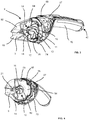
- FIG. 11 shows a perspective view of the suction device 2 from FIG Figure 1 .
- the upper part of the receptacle of the suction nozzle 62 can be seen, in which the suction nozzle 4, which is designed as a flat nozzle, is detachably inserted via the clamp connection. Due to the detachable connection, other suction nozzles can also be used in the intake of the suction nozzle, depending on the area of application.
- the closure 42 continuing the outer contour of the device 2 is shown spaced apart from the suction device 2 in the dismantled state.
- the closure 42 has at the end a gripping area which is formed by a raised edge in the form of a retaining bead 76 in the rear area.
- FIG. 3 shows a further view of the suction device 2 according to the invention from the previous figures.
- the suction device 2 is shown with a cut-free separation area and without an upper housing shell 64 and without a closure 42.
- the suction material sucked in by the suction nozzle 4, not shown, is transferred into the separation area via a suction channel 3 arranged in the receptacle for the suction nozzle 62, separated from the exhaust air flow by the separation device 12 and transferred into an inlet opening 36 arranged in the lower part of the suction device 2.
- the inlet opening 36 leads into a suction material guide 30, via which the suction material is in turn directed into the suction material container 8.
- the individual components of the separation device 12 can be seen, which comprises a ramp-shaped suction material guide element 14 and a rotary separator 16.
- the rotary separator 16 is shown in FIG Embodiment connected in one piece to the fan wheel 11 of the suction unit 10.
- the separation area is designed as a separation chamber 18.
- the delimitation forming the separation chamber 18 is made in two parts.
- the first part is formed by a cup-shaped first delimiting element 92, in the bottom area of which the beak-shaped receptacle for the suction nozzle 62 is also formed.
- the cup-shaped delimiting element 92 is formed by the first housing part and is thus also part of the suction device housing 6.
- the cover element 94 has two openings.
- the rotary separator 16 which is integrally connected to the fan wheel 11, is arranged in the first opening, which is arranged centrally in the cover element 94 and is an exhaust air opening.
- the exhaust air flow from which the suction material has been removed is conveyed to the outside through the exhaust air opening from the separation chamber 18 via the fan wheel 11 through the ventilation slots 66 in the suction device housing 6.
- the second opening is an outlet opening of the separation chamber 18 for the separated suction material and is at the same time the inlet opening 36 into the suction material guide 30.
- the Figure 4 shows the suction device 2 according to the invention again Figure 3 with separation chamber 18, but in the present case with uncut cover element 94.
- Screw openings 96 can be seen via which the cup-shaped delimiting element 92 is connected to an intermediate element 23 for the suction unit 10 designed as a component carrier.
- the cup-shaped delimiting element 92 of the separation area has openings corresponding to the screw openings 96, via which the cup-shaped delimiting element 92 is connected to the cover element 94, the intermediate element 23, the second housing part designed as a cover element 27 and the grip shell 70.
- a sealing element 58 in the form of a sealing ring is injection molded onto the cover element 94, which in the assembled state interacts with a sealing groove 59 provided on the cup-shaped delimiting element 92 and seals the two components against the escape of liquid.
- the side view of the suction device 2 from the previous figures with a sectioned suction and separation area shows Figure 5 .
- the upper housing shell 64, the closure 42 and the suction nozzle 4 which can be plugged into the beak-shaped receptacle 62 are not shown.
- the suction channel 3 extends into the separation chamber 18.
- the separation chamber 18 is formed by the cup-shaped delimiting element 92 and the cover element 94, the cup-shaped delimiting element 92 as the first housing part of the multi-part housing forming part of the housing of the suction device 6.
- the suction channel 3 extends at least partially into the separation chamber 18.
- the suction channel 3 has two clamping lugs which extend into the separation chamber 18.
- a suction material guide element 14 is clamped onto the suction duct 3 as a separate part via the clamping lugs of the suction duct 3 and initially has an opening area which forms an extension of the suction duct 3.
- the suction material guide element 14 has a ramp-shaped shape and bends after the mouth area in the direction of the inlet opening 36 of the suction material guide. Due to the design, the suction material is guided in a direction that deviates from the suction material flow because of its inertia and the force of gravity acting on the suction material.
- a reaching-in guard 21 is arranged within the suction material guide element 14.
- the plate-shaped cover element 94 has a conical inlet connection 20 on the side facing the suction nozzle 4.
- FIG. 6 A perspective view of parts of the suction device 2 from the previous figures shows Figure 6 .
- the suction material container 8 is largely arranged in the handle 48.
- One wall of the suction material container 8 forms the grip shell 70, which forms the lower part of the housing 6, and towards the top the cover element (not shown), which is connected to the grip shell 70 in a sealing manner against the escape of suction material.
- a further wall of the suction material container 8 forms a shell component 32 inserted into the handle shell 70.
- the shell component 32 is a separate component and is connected to the handle shell 70 via a clamp connection.
- retaining lugs 38 are provided in the region of an inlet opening 36, symmetrically spaced from the longitudinal axis of the suction device 2, on the shell component 32, which lugs have correspondingly designed retaining projections 39 interact in a clamping manner on the grip shell 70.
- a retaining projection 39 is provided which, for the clamping connection, interacts with a corresponding retaining lug 38 which is integrally connected to the grip shell 70.
- the inlet opening 36 is provided in the suction material guide 30.
- the suction material separated in the separating device is passed through the inlet opening 36 into the suction material guide 30 and from there into the suction material container 8.
- the suction material container 8 can then be emptied by opening the closure 42.
- the suction material guide 30 is constructed in several parts.
- the geometrical delimitation of the suction material guide 30 is effected by the shell component 32 and, on the other hand, by areas of the grip shell 70.
- the third housing part not only forms part of the suction material container 8, but also forms part of the geometrical delimitation of the suction material guide 30.
- Shell component 32 is a separate component which is connected to the handle shell 70. Sealing means or sealing elements 58 are provided between the area of the shell component 32 and the area of the handle 70, which each form the geometric delimitation of the suction material guide 30, which prevent suction material from escaping from the suction material guide outside the inlets and outlets 36, 34.
- the sealing elements 58 are designed as a circumferential seal which is molded onto the shell component. Corresponding to the molded seal on the shell component 32, a corresponding sealing groove is provided in the handle shell 70. Alternatively, a second shell component can also be used in order to form the suction material guide together with the shell component 32.
- the advantage of this construction is that complex geometries can also be mapped, since in particular the handle shell 70 and the shell component 32 can be manufactured as a half-shell and in particular cavities and undercuts in the suction material guide 30 can be implemented in terms of production and assembly due to the multi-part construction of the suction material guide 30 . Furthermore, it is also easily possible to provide cutouts 82 in the shell component 30.
- an opening is formed in the handle shell 70 through which cabling for a charging connection of a das Suction unit comprehensive accumulator is carried out.
- the charging connection cannot be arranged directly visible to the user on the underside of the device 2 in the handle shell 70.
- the shell component 32 can be arranged through a recess 82 surrounding the opening in the handle shell 70.
- a positioning receptacle 80 in which a part of the upper cover element, not shown, can be arranged in a supporting and / or centering manner.
- Figure 7 shows the second housing part designed as a cover element 27 with a receiving area 22 in a view obliquely from the front.
- the receiving area 22, which is designed as a hollow body, has a rectangular cross section with a rounded top and bottom on the side of the receiving area 22 facing the suction nozzle 4.
- the rectangular cross section is provided to accommodate the electric motor 24, the accumulator 26 and the circuit board 25 together with their respective holders.
- the geometrically longer pocket for the accumulator 26 is provided in the part of the receiving area 22 directed towards the upper side of the suction device 2, whereby this is essentially round in cross section, corresponding to the cross section of the accumulator 26.
- a seat for a motor shaft bearing 87 of the electric motor 24 is provided in the part of the receiving area 22 that receives the electric motor 24, a seat for a motor shaft bearing 87 of the electric motor 24 is provided.
- This receptacle for the motor shaft bearing 87 is arranged concentrically with the electric motor 24 and with the fan wheel 11 driven by the latter.
- a positioning recess 89 is provided immediately next to the receptacle for the motor shaft bearing 87. This engages in a positioning receptacle 80 in a shell component 32, which is arranged below the receiving area 22 and forms part of the suction material guide 30, and ensures correct positioning of the shell component 32.
- a cable opening 88 is provided in the direction of the suction material guide 30, through which the cables for a charging connection on the underside of the suction device 2 when the suction device 2 is installed.
- a sealing element is located on the underside of the receiving area 22 provided, which seals the cable opening 88 in the receiving area 22 against entry of suction material.
- the sealing element is designed as a circumferential seal and interacts with a corresponding sealing groove on the shell component 32.
- the cover element 27 On the top of the cover element 27, in the part of the receiving area 22 facing the suction nozzle 4, a part of the cover element 27, which is arranged above the actuating button 68 on the circuit board 25 when the suction device 2 is installed, is formed as an elastic housing area 69.
- the actuating button 68 can be actuated in the assembled state through the elastic housing area 69 to switch the suction device 2 on and off.
- the elastic housing area 69 is formed from a soft material, in particular a rubber-like material.
- a recess is provided in the cover element 27, which is overmolded with a soft plastic forming the soft material.
- the overmolded area can extend beyond the elastic housing area 69 and forms an elevation 67 on the cover element 27.
- the upper housing shell 64 has, as in FIG Figure 2 shown, a recess corresponding to the overmolded area.
- the recess interacts with the elevation through the overmolded area 67 and thus facilitates the assembly of the upper housing shell 64, the overmolded area 67 preferably flush with the outer surface of the upper housing shell 64, possibly leaving a gap.
- part of the elastic housing area 69 is designed to be translucent. Furthermore, an LED is provided below the translucent area of the housing, preferably on the circuit board, which indicates an operating state of the suction device 2.
- the grip shell 70 forms the bulbous part of the suction device 2 up to the end of the receiving area 22 pointing towards the closure 42, and from there it merges into the handle 48. In this way, a particularly advantageous use of the installation space is achieved.
- FIG Figure 8 A perspective front and rear view of the intermediate element 23 designed as a component carrier is shown in FIG Figure 8 .
- the intermediate element 23 has four centering openings 29 which are arranged symmetrically distributed over the intermediate element 23.
- the upper part of the intermediate element 23 has a half-shell reinforced by ribs, which extends in the direction of the rotary separator 16.
- the height of the half-shell is designed in such a way that it lies above the height of the radially outer region of the fan blades of the fan wheel 11. In the embodiment shown, the half-shell extends between two centering openings, the upper two. In this way, better support between the centering or positioning elements 90 of the cover element 27 and the centering openings 29 of the intermediate element 23 is achieved.
- the provision of the half-shell serves to discharge the exhaust air flow in a directed manner out of the suction device 2, in particular via the sides of the suction device 2.
- a cover element designed as a plate-shaped delimitation element of the separation area is placed on the intermediate element 23 in the direction of the rotary separator and closes the area of the half-shell.
- the lower two centering openings 29 of the intermediate element 23 are positioned in the assembled state of the device on both sides of the semicircular inlet opening 36 in the suction material guide 30.
- the cover element 94 is sealingly placed on the inlet opening 36 in the suction material guide 30. Due to the laterally open areas formed between the intermediate element 23 and the cover element 94, the exhaust air flow is guided out of the suction device 2 through the ventilation slots 66 in the upper housing cover 64.
- a sealing element 58 designed as a circumferential seal is provided, the sealing element 58 being rectangular, corresponding to the rectangular opening of the receiving area 22, such that the intermediate element 23 seals the receiving area 22 against the ingress of suction material able.
- the seal is molded onto the intermediate element 23 and forms a flat sealing contour.
- the component receiving elements 28, in which the electric motor 24, the accumulator 26 and the circuit board 25 are held, are provided spatially within the circumferential seal on the intermediate element 23.
- the component receiving elements 28 are integrally connected to the intermediate element 23.
- the component receiving elements 28 do not completely enclose the electronic components in order to enable good heat dissipation, but also good support for the components.
- the circuit board comprises the actuation button 68 for switching the suction device 2 on and off as well as the LED, which indicates the operation of the suction device 2.
- a housing of the electric motor 24 has a rectangular cross section.
- the component receiving element 28 holding the electric motor 24 holds the electric motor 24 only on the housing covers, the part of the housing of the electric motor 24 facing away from the intermediate element 23 being covered less by the component receiving element 28 than the part facing the intermediate element 23.
- the temperature-sensitive accumulator 26 in particular is at least partially shielded from the waste heat from the electric motor 24.
- a complete, more solid enclosure of the electric motor 24 by the component receiving element 28 can be dispensed with, since the electric motor 24 is mounted for low-vibration operation of the fan wheel 11 via the motor shaft bearing 86, which is received in the receptacle for the motor shaft bearing 87 in the receiving area 22.
- inserted soft elements are provided which are set up in such a way that a secure fit of the electronic components, in particular of the electric motor 24 and the accumulator 26, is achieved. Furthermore, soft elements are also provided on the outside of the component receiving elements 28 in order to also hold the component receiving elements 28 securely in the receiving area 22.
- FIG. 9 A more detailed section of the suction and separation area is shown in Figure 9 in a sectional view.
- the recording of the suction material guide element 14 in the suction channel 3 is shown, which is inserted into the first housing part.
- the cup-shaped delimiting element 92 and the cover element 94 placed on the fan wheel 11 are shown assembled and form the separation chamber 18. Furthermore, the intermediate element 23 is also connected to the cup-shaped delimiting element 92 and the cover element 94 in the illustration.
- the second housing part designed as a cover element 27 is connected to the third housing part designed as a grip shell 70 via a clamp and screw connection.
- the intermediate element 23 and the cover element 94 are the intermediate element 23 and the cover element 94, as in FIG Figure 3 shown, postponed.
- the first housing part is placed on the cover element 94 and screwed to it, the centering and positioning elements of the cover element 27 and the grip shell 70 having threads.
- the upper housing shell 64 is pushed from the side of the suction nozzle 4 over the remaining housing parts and covers the connection area of the first housing part with the cover element 94, the intermediate element 23, and the cover element 27 and the handle shell 70 Increase in the overmolded area 67 be kept.
- the upper housing shell is braced and fastened by abutment against the lower handle shell 70 and the soft material applied to it and a screw connection on the side of the opening of the suction material container 8 below the closure 42. In this way, no connection point on the device is visible to the outside.
- the assembled suction device 2 without suction nozzle shows in a perspective view Figure 10 .
Landscapes
- Engineering & Computer Science (AREA)
- Mechanical Engineering (AREA)
- External Artificial Organs (AREA)
- Hooks, Suction Cups, And Attachment By Adhesive Means (AREA)
Description
- Die Erfindung betrifft ein tragbares Sauggerät nach dem Oberbegriff des Anspruchs 1. Insbesondere betrifft die Erfindung ein tragbares Sauggerät mit einem in eine Saugdüse mündenden Saugkanal und mit einem Gehäuse, einem Griff, einem Sauggutbehälter mit einer Öffnung, einem die Öffnung verschließenden Verschluss, und einem Saugaggregat zur Erzeugung einer Saugströmung, die einen an der Saugdüse anliegenden Saugunterdruck bereitstellt, mit einer Abscheideeinrichtung, die die über die Saugdüse angesaugte Saugströmung in eine aus dem Sauggerät strömende Abluftströmung und in Sauggut in Form von Partikeln und/oder Fluidbestandteilen aufzuteilen vermag, wobei die abgeschiedenen Partikel oder Fluidbestandteile in dem Sauggutbehälter gesammelt sind und durch Öffnen des Verschlusses der Sauggutbehälter entleert werden kann. Insbesondere weisen diese Geräte auch eine Abziehlippe zum Abziehen von Flüssigkeiten auf, wobei die Abziehlippe an der Saugdüse angeordnet ist. Zudem sind diese Geräte üblicherweise batteriebetrieben und werden in der Hand eines Benutzers gehalten, während dieser die Abziehlippe entlang der abzusaugenden Fläche führt.
- Tragbare Geräte dieser Art sind unter anderem aus der
EP 2 845 530 B1 bekannt. Die bekannten Sauggeräte werden verwendet, um ein Flüssigkeit-/Luftgemisch aufzusaugen. Dies kann, wie im Fall der genannten Vorrichtung, zum Aufsaugen von Flüssigkeit, zum Beispiel von einer ebenen Oberfläche wie einer Tischplatte, von Fensterscheiben oder Fliesen erfolgen. Zum rückständefreien Reinigen der Oberflächen ist bei den gattungsgemäßen Geräten eine an der Saugdüse angeordnete Abziehlippe vorgesehen. - Das Sauggut wird bei den Sauggeräten in einem Sauggutbehälter gespeichert und muss daher aus der Saugströmung vom Luftstrom separiert werden. Die bekannten Abscheideeinrichtungen der tragbaren Saugeräte, nutzen um das Sauggut von der Saugströmung zu trennen, Prallplatten und Luftumlenkungen.
- Derart gestaltete Sauggeräte weisen Nachteile auf. So verursachen scharfe Luftumlenkungen und Prallplatten Druckverluste, die den Wirkungsgrad des Sauggeräts negativ beeinflussen. Dies äußert sich für den Nutzer in einer kürzeren Gerätelaufzeit bei gegebener nutzbarer Kapazität des Akkumulators. Zudem bauen derartige Geräte entsprechend größer.
- Eine weitere Anforderung an die gattungsgemäßen Sauggeräte ist es, das Rückströmen des Saugguts zurück in den Abscheidebereich zu vermeiden. Bei den bekannten Sauggeräten wird das Sauggut zunächst in einem Abscheidebereich abgeschieden. Das Sauggut wird anschließend über eine Sauggutführung in den Sauggutbehälter überführt. Um ein Rückströmen des Saugguts zurück in den Abscheidebereich zu verhindern, wird der Auslass der Sauggutführung regelmäßig mittig in dem Sauggutbehälter positioniert. Auf diese Weise wird um den Auslass der Sauggutführung ein Ausweichvolumen geschaffen, in das das bereits im Sauggutbehälter gespeicherte Sauggut beim Verschwenken des Geräts zwischengespeichert wird.
- Bei den Sauggutführungen der gattungsgemäßen Saugeräte sind herstellungsbedingt nur einfache Geometrien möglich, die einen erhöhten Bauraumbedarf bedingen.
- Um das Sauggut aus dem Sauggutbehälter abzulassen haben die Sauggeräte oftmals am Sauggutbehälter einen als kleinen Stopfen ausgeführten Verschluss. Ferner ist der Sauggutbehälter meist separat herausnehmbar ausgestaltet und hat zusätzlich eine größere Öffnung für eine bessere Reinigung. Auch ist die größere Öffnung aus Gründen der Montierbarkeit vorgesehen, um die Montage von innen liegenden Teilen wie beispielsweise der Sauggutführung zu ermöglichen.
- Bei den gattungsgemäßen Geräten ist das Entleeren des Sauggutbehälters aufwendig und langwierig und damit nicht anwendungsfreundlich. Oftmals müssen einige Bauteile des Sauggeräts zunächst demontiert werden und je nach Sauggerät auch Verbindungselemente gelöst werden, um den Sauggutbehälter zu entleeren und zu reinigen. Bei der Entleerung über einen als Stopfen ausgeführten Verschluss ist ein restloses Entleeren häufig nicht möglich, da oftmals geringe Sauggutmengen in durch die Sauggutbehältergeometrie gebildeten Saugguttaschen überbleiben. Um die Dichtigkeit des Verschlusses sicherzustellen, ist es üblicherweise erforderlich die Verschlüsse der gattungsgemäßen Sauggeräte mit einer runden Geometrie und Dichtkontur auszugestalten. Hieraus resultieren gestalterische Einschränkungen in Bezug auf die Lage und Ausgestaltung des Verschlusses und damit auf das Design des Sauggeräts. Darüber hinaus haben die Geräte durch die mehreren Öffnungen und entsprechenden Verschlüsse, insbesondere bei einem separat herausnehmbaren Sauggutbehälter, eine größere Bauform.
- Ferner muss bei den gattungsgemäßen Sauggeräten ein Schutz der elektronischen Bauteile vorgesehen sein, insbesondere wegen ihrer vielfältigen Einsatzbereiche. Diese reichen von einem normalen Verschwenken des Geräts um 180° bis hin zu einem Überkopfbetrieb bei der Reinigung von beispielsweise Wintergärten. Zum Schutz der elektronischen Bauteile des Geräts muss für einen sicheren und zuverlässigen Betrieb verhindert werden, dass die elektronischen Bauteile mit dem eingesaugtem Sauggut, insbesondere Flüssigkeit und Staub, in Kontakt kommen. So ist beispielsweise in dem Dokument
EP 3 021 723 A1 ein tragbares Sauggerät beschrieben, welches eine separate wasserdichte Einheit, die den Elektromotor, den Akkumulator und die Bauteilelektronik umfasst, vorsieht. Die separate Einheit ist in dem Gehäuse des Sauggeräts verbaut. - Die Integration einer separaten gekapselten Einheit in das Gehäuse des Saugeräts erfordert, um Toleranzen für den Zusammenbau der Bauteile einzuhalten, eine passgenaue Ausführung der Einheit und des Gehäuses. Dies bedingt in nachteiliger Weise mit höheren Kosten verbundene höhere Anforderungen an die Fertigung der Bauteile. Zudem führt die Kapselung durch die separate Einheit innerhalb des Gehäuses von Elektromotor, Akkumulator und Elektronik zu einer erhöhten Erwärmung der Komponenten.
- Es ist daher Aufgabe Erfindung zumindest einen der zuvor genannten Nachteile zu überwinden. Insbesondere ist es Aufgabe der Erfindung ein tragbares Sauggerät bereitzustellen, welches eine kompakte Bauform bei guter Wärmeableitfähigkeit, bei kostengünstiger Herstellung und leichter Montage ermöglicht.
- Die Lösung der Aufgabe erfolgt erfindungsgemäß durch ein tragbares Sauggerät mit den Merkmalen des Anspruchs 1. Bevorzugte Ausgestaltungen der Erfindung sind in den Unteransprüchen und der nachfolgenden Beschreibung angegeben, die jeweils einzeln oder in Kombination einen Aspekt Erfindung darstellen können.
- Erfindungsgemäß ist vorgesehen, dass das Gehäuse mehrteilig ausgebildet ist. Das Gehäuse weist einen ersten Gehäuseteil auf, von dem der Ansaug- und Abscheidebereich in dem die Abscheideeinrichtung angeordnet ist, aufgenommen und/oder ausgebildet ist. Weiter ist ein zweiter Gehäuseteil mit einem dritten Gehäuseteil verbunden und der Sauggutbehälter ist zwischen dem zweiten und dritten Gehäuseteil angeordnet. Verbindungsbereiche des ersten Gehäuseteils mit den anderen Gehäuseteilen sowie Verbindungsbereiche der Verbindung des zweiten und dritten Gehäuseteils sind durch ein Abdeckgehäuseteil abgedeckt. Dabei ist insbesondere ein Verbindungsbereich vorgesehen, in dem das erste, zweite und dritte Gehäuseteil miteinander verbunden sind.
- Bei einer bevorzugten Ausgestaltung sind die Verbindungsbereiche des ersten Gehäuseteils mit einem angrenzenden Bauteil und/oder des zweiten Gehäuseteils mit dem dritten Gehäuseteil vollständig durch das Abdeckgehäuseteil abgedeckt. Bevorzugt umschließt das Abdeckgehäuseteil zumindest teilweise die Gehäuseteile in Form einer Hülse. Die Form des Sauggeräts ist in einer besonders vorteilhaften Ausgestaltung der Erfindung so ausgebildet, dass sich das Sauggerät auf dem der Saugdüse gegenüberliegenden Endabschnitt in den Griff erstreckt.
- Es ist in Bezug auf die Montage von Vorteil, wenn das Abdeckgehäuseteil von der Seite der Saugdüse über die Gehäuseteile geschoben ist. Besonders bevorzugt verjüngt sich hierfür das auf Seiten der Saugdüse angeordnete erste Gehäuseteil konusförmig in Richtung Saugkanal.
- Die Befestigung des Abdeckgehäuseteils kann durch eine Klemm-, Rast- und/oder Schraubverbindung erfolgen. In vorteilhafter Weise ist zumindest an einem der Gehäuseteile, bevorzugt am zweiten oder dritten Gehäuseteil, ein Anlagebereich vorgesehen, gegen den das Abdeckgehäuseteil geschoben und über eine Klemmund/oder Schraubverbindung befestigt werden kann.
- Bei der Ausgestaltung des Sauggeräts mit einseitigem Griff bildet der Verschluss bevorzugt das distale Ende des Griffs, wobei der Verschluss mittels einer doppelwandigen Konstruktion so ausgeführt sein kann, dass die Formgebung des Sauggeräts über eine Außenkontur des Verschlusses fortgeführt ist. Hierfür ist der Verschluss aus zumindest einem ersten Verschlusselement und einem zweiten Verschlusselement gebildet, derart, dass das erste Verschlusselement dazu eingerichtet ist, die Öffnung des Sauggutbehälters gegen Austritt von Sauggut abzudichten und das zweite Verschlusselement außerhalb des ersten Verschlusselements angeordnet ist. Bevorzugt ist der Verschluss, also das erste und zweite Verschlusselement, einstückig ausgebildet. Insbesondere ist das zweite Verschlusselement von dem ersten Verschlusselement beabstandet. Dabei kann das zweite Verschlusselement glockenartig um das erste Verschlusselement angeordnet sein.
- Um eine besonders kompakte Bauweise des Sauggeräts zu realisieren, ist der Sauggutbehälter in vorteilhafterweise fest im Sauggerät integriert. Auch kann der Sauggutbehälter durch das Gehäuse des Sauggeräts, besonders bevorzugt durch das zweite und dritte Gehäuseteil, gebildet sein. Ferner kann der Sauggutbehälter zumindest teilweise im Griff des Sauggeräts angeordnet sein. Zudem kann vorgesehen sein, dass der Griff mehrteilig ausgebildet ist und das zweite Gehäuseteil und das dritte Gehäuseteil den Griff bilden.
- Als weitere Maßnahme für ein kompaktes Gerät mit kompaktem Gehäuse kann vorgesehen sein, dass zwischen Saugkanal und Sauggutbehälter eine Sauggutführung vorgesehen ist, durch die das Sauggut bei bestimmungsgemäßer Verwendung des Sauggeräts in den Sauggutbehälter gelangt, wobei die geometrische Begrenzung der Sauggutführung mehrteilig ausgebildet ist und zumindest durch ein separates Schalenbauteil gebildet ist. Auf diese Weise wird eine Sauggutrückströmung zurück in den Abscheidebereich bzw. in eine Abscheidekammer beim Verschwenken des Geräts vermieden. Zudem hat eine solche Ausgestaltung den Vorteil, dass durch das Verbinden von zwei Halbschalen eine komplizierte, gewundene und gewinkelte Konstruktion der Sauggutführung möglich ist, sodass ein gewünschtes Sauggerätedesign ausgebildet werden kann und insbesondere auch der zur Verfügung stehender Bauraum vollständig ausgenutzt werden kann.
- Ferner bietet die Lösung eine einfache Herstellerbarkeit, da lediglich einfache Schalenbauteile hergestellt werden müssen. Die geometrische Begrenzung der Sauggutführung kann zum Teil durch einen Wandbereich des Sauggutbehälters gebildet sein. Besonders bevorzugt kann der Wandbereich auch einen Teil des Gehäuses des Sauggeräts, insbesondere des dritten Gehäuseteils, bilden.
- Um eine besonders kompakte Bauform zu erreichen, ist bevorzugt vorgesehen, dass der Sauggutbehälter und die Sauggutführung zumindest teilweise im Griff angeordnet sind. Eine vorteilhafte Ausgestaltung des erfindungsgemäßen Sauggeräts sieht vor, dass die Sauggutführung zumindest teilweise, insbesondere vollständig im Sauggutbehälter angeordnet ist. Die geometrische Begrenzung der Sauggutführung ist besonders bevorzugt zum Teil durch einen Bereich des einen Teil des Griffs bildenden dritten Gehäuseteils gebildet. Als besonders vorteilhaft für die Montage hat sich herausgestellt, dass das zumindest eine separate Schalenbauteil lösbar befestigt, insbesondere verklemmt und/oder verschraubt, innerhalb des Gehäuses, bevorzugt befestigt am dritten Gehäuseteil, angeordnet ist. Als lösbare Verbindung zum Halten des Schalenbauteils können beispielsweise Klemmnasen und/oder Schnapphaken am Gehäuse und/oder Schalenbauteil vorgesehen sein.
- Das Saugaggregat umfasst zumindest einen Elektromotor und einen Akkumulator und ein Lüfterrad, welches vom Elektromotor angetrieben ist. Elektromotor und Ackumulator können zwischen dem zweiten und dritten Gehäuseteil angeordnet sein. Als weitere Maßnahme für ein kompaktes Sauggerät können der Elektromotor und der Akkumulator dabei innerhalb des Sauggutbehälters angeordnet sein, wobei das zweite Gehäuseteil bevorzugt einen Aufnahmebereich für den Elektromotor und Akkumulator vorsieht und der Aufnahmebereich einen Teil der Sauggutbehälterbegrenzung bildet.
- In einer weiteren bevorzugten Ausgestaltung des Sauggeräts ist zwischen dem ersten Gehäuseteil, der den Ansaug- und Abscheidebereich aufnimmt und den Gehäuseteilen, die den Sauggutbehälter aufnehmen, das Lüfterrad des Saugaggregats angeordnet. Weiterhin kann bevorzugt zwischen dem ersten Gehäuseteil mit einem von dem zweiten Gehäuseteil und den dritten Gehäuseteil gebildeten hinteren Gehäusebereich ein Zwischenelement vorgesehen sein, an dem zum einen das erste Gehäuseteil und zum anderen der hinteren Gehäusebereich befestigt ist. Bevorzugt ist am Lüfterrad ferner ein Rotationsabscheider vorgesehen, der Teil der Abscheideeinrichtung ist und in den Abscheidebereich hineinragt. Zwischen Abscheidebereich und Lüfterrad ist dabei ein Abdeckelement vorgesehen, durch den der Rotationsabscheider in Richtung Saugdüse in den Abscheidebereich hineinragt.
- Bevorzugt kann bei dem erfindungsgemäßen Sauggerät als Abscheidebereich eine Abscheidekammer vorgesehen sein. Diese ist in vorteilhafterweise zwischen Saugkanal und Sauggutbehälter angeordnet, wobei die Abscheidekammer durch das erste Gehäuseteil des Sauggeräts und das Abdeckelement begrenzt ist. In der Abscheidekammer sind dabei zumindest eine Zulauföffnung für die Saugströmung durch den Saugkanal und eine Abluftöffnung für die Abluftströmung und eine Ablauföffnung für das Sauggut in dem Abdeckelement vorgesehen. Die Abluftöffnung ist dabei bevorzugt die Öffnung im Abdeckelement, durch die der Rotationsabscheider ragt.
- Dabei bildet ein Sauggutleitelement in einer bevorzugten Ausführungsform für ein kompakte Bauweise eine erste Stufe der Abscheidung. Dieses kann in einer vorteilhaften Ausführungsform unmittelbar in Richtung Sauggutbehälter ausgerichtet sein. Eine zweite Stufe der Abscheidung ist durch den Rotationsabscheider gebildet.
- Bevorzugt ist ferner vorgesehen, dass der Sauggutbehälter mittelbar über eine Sauggutführung oder unmittelbar eine Einlassöffnung aufweist. Das Abdeckelement weist dabei eine zur Einlassöffnung des Sauggutbehälters korrespondierende weitere Öffnung auf, wobei die Einlassöffnung insbesondere mittelbar über einen Einlass einer Sauggutführung gebildet ist. Bei Geräten mit Abscheidekammer kann die weitere Öffnung die zuvor erwähnte Ablauföffnung aus der Abscheidekammer sein.
- Eine bevorzugte Ausgestaltung der Erfindung des tragbaren Sauggeräts sieht vor, dass ein Teil der Sauggutbehälterbegrenzung, bevorzugt das zweite Gehäuseteil, einen Aufnahmebereich zur Aufnahme von elektronischen Komponenten des Sauggeräts aufweist, wobei der Aufnahmebereich in Form zumindest eines bis auf die Öffnung wasserdicht ausgebildeten Hohlraums gebildet ist und durch das separate Zwischenelement wasserdicht verschließbar ausgebildet ist.
- Die elektronischen Komponenten umfassen zumindest den Elektromotor und den Akkumulator, können aber auch weitere elektronische Bauteile, wie beispielsweise auf einer Platine angeordnete Überwachungs- und/oder Steuerelemente umfassen.
- Der Hohlraum kann aus einer oder mehreren Taschen bestehen, wobei die einzelnen elektronischen Komponenten in den Taschen angeordnet sind.
- Durch den wasserdicht verschlossenen Hohlraum in der Saugbehälterbegrenzung werden die elektronischen Komponenten gegen Eindringen von Staub und Wasser geschützt. Weiterhin weist die Anordnung keine wärmeisolierende Verkapselung der Bauteile auf, so dass die beim Betrieb des Geräts entstehende Verlustwärme gut abgeführt werden kann. Dies kann direkt über das Gehäuse an die Umgebung und zudem noch in das aufgesaugte Sauggut erfolgen.
- Bevorzugt bildet das separate Zwischenelement einen Bauteilträger, von dem zumindest der Elektromotor und der Akkumulator gehalten sind. Das Lüfterrad ist dabei in vorteilhafterweise auf der dem Aufnahmebereich abgewandten Seite des Zwischenelements am Zwischenelement angeordnet, drehbar gelagert.
- Das Zwischenelement ist in einer besonders vorteilhaften Ausgestaltung der Erfindung zwischen dem ersten Gehäuseteil einerseits und dem zweiten und dritten Gehäuseteil anderseits angeordnet, wobei das Zwischenelement Teil des durch das Abdeckgehäuseteil abgedeckten Verbindungsbereichs ist.
- Um das Gerät nach der Benutzung abstellen zu können weist das Sauggerät zwei Abstellbereiche auf. Die Abstellbereiche sind derart angeordnet und eingerichtet, dass die Saugdüse beim bestimmungsgemäßen abstellen des Sauggeräts auf einer ebenen Abstellfläche von der ebenen Abstellfläche beabstandet ist. In vorteilhafterweise können die Abstellbereiche aus einem Weichmaterial gebildet sein. Dies verhindert Kratzer beim Abstellen des Geräts auf der Abstellfläche.
- Das Sauggerät erstreckt sich bevorzugt auf der von der Saugdüse abgewandten Seite in den Griff. Der Verschluss kann dabei das distale Ende des Griffs bilden und als einer der zuvor genannten Abstellbereiche fungieren.
- Ein weiterer Abstellbereich kann in dem der Saugdüse zugewandten Teil des Sauggeräts vorgesehen sein. Dieser kann insbesondere durch zwei Auflager bzw. Füße gebildet sein. Diese können für eine verbesserte Stabilität symmetrisch beabstandet von einer Längsachse des Gerätes angeordnet sein.
- Bevorzugt kann das dritte Gehäuseteil eine Gehäuseunterseite bilden und an der Oberfläche des dritten Gehäuseteils zumindest teilweise ein Weichmaterial vorgesehen sein. Das Weichmaterial ist bevorzugt in Dicke und Material derart ausgewählt, dass das Sauggerät bei Berührung mit einer Oberfläche gegen Stöße geschützt ist. Auch kann das Weichmaterial zudem so auf der Oberfläche des Sauggeräts angebracht sein, dass eine Beschädigung von Oberflächen, mit der das Sauggerät in Berührung kommt, vermieden ist. Die als Abstellbereich fungierenden Auflager können dabei ebenfalls aus dem teilweise auf dem dritten Gehäuseteil vorgesehenen Weichmaterial gebildet sein und insbesondere aus diesem hervorgehen.
- Das Gehäuse des Sauggeräts ist bevorzugt aus einem harten Kunststoff gebildet, auf den das Weichmaterial aufgebracht ist. Fertigungstechnisch kann dies in vorteilhafterweise durch eine 2-Komponenten Spritzgusstechnik realisiert sein. Der harte Kunststoff ist bevorzugt transparent ausgebildet. Auf diese Weise kann der Benutzer den Füllstand des Sauggutbehälters sehen.
- In einer weiteren bevorzugten Ausführungsform ist innerhalb des Gehäuses eine Platine mit einem Betätigungsknopf bzw. Betätigungselement angeordnet. Der Betätigungsknopf ist dabei eingerichtet das Gerät an- und auszuschalten. Die Platine ist bevorzugt in einem Aufnahmebereich des einen Teil der Sauggutbehälterbegrenzung bildenden zweiten Gehäuseteils angeordnet. Oberhalb des Betätigungsknopfes kann ein elastischer Gehäusebereich vorgesehen sein, über den der Betätigungsknopf betätigt werden kann. Der elastische Gehäusebereich ist vorzugsweise im zweiten Gehäuseteil vorgesehen. Der bevorzugt über dem zweiten Gehäuseteil angeordnete Abdeckgehäuseteil kann dabei eine Aussparung aufweisen, durch die der elastische Gehäuseteil zum betätigen des Betätigungsknopfes betätigt werden kann.
- Bevorzugt ist der elastische Gehäusebereich als ein Weichmaterial auf einen härteren Kunststoff aufgespritzt. Der härtere Kunststoff weist an der Stelle oberhalb des Betätigungsknopf eine Aussparung auf, welche von dem angespritzten Weichmaterial abgedeckt ist. Fertigungstechnisch kann dies vorteilhafterweise im 2 Komponentenspritzguss erfolgen. Vorzugsweise bildet das angespritzte Weichmaterial eine derartige Wandung, dass sich die Wandung durch die Aussparung im Abdeckgehäuseteil erstreckt und so das Abdeckgehäuseteil zusätzlich ausgerichtet und/oder gehalten ist.
- Um einen Betrieb des Sauggeräts für den Benutzer optisch kenntlich zu machen, kann auf der Platine ein Leuchtmittel zum Anzeigen des Betriebs des Sauggeräts angeordnet sein. Der elastische Gehäusebereich kann hierfür teilweise transparent ausgebildet sein, derart, dass das Leuchtmittel durch den transparenten Bereich scheint. Als Leuchtmittel kann bevorzugt eine LED verwendet werden.
- Weitere Merkmale und Vorteile der Erfindung ergeben sich der nachfolgenden Beschreibung bevorzugter Ausführungsbeispiele anhand der Zeichnungen.
- In den Zeichnungen zeigt:
- Fig. 1
- eine Seitenansicht des erfindungsgemäßen Sauggeräts in einer ersten Ausführungsform,
- Fig. 2
- eine perspektivische Ansicht des erfindungsgemäßen Sauggeräts aus
Fig. 1 mit abgezogenem Verschluss, - Fig. 3
- eine perspektivische Ansicht des erfindungsgemäßen Sauggeräts mit freigeschnittenem Abscheidebereich,
- Fig. 4
- eine perspektivische Ansicht der Ausführungsform aus
Fig. 3 mit nicht geschnittenem Abdeckelement, - Fig. 5
- eine Seitenansicht des Sauggeräts aus den vorherigen Figuren mit geschnittenem Ansaug- und Abscheidebereich,
- Fig. 6
- eine perspektivische Ansicht einer Griffschale des Sauggeräts mit eingesetztem Schalenbauteil,
- Fig. 7
- eine perspektivische Ansicht des zweiten Gehäuseteils mit Aufnahmebereich,
- Fig. 8
- eine perspektivische Ansicht einer Ausführungsform des als Bauteilträger ausgeführten Zwischenelements,
- Fig. 9
- einen Ausschnitt des Ansaug- und Abscheidebereichs von schräg hinten, und
- Fig. 10
- das montierte Sauggerät ohne Saugdüse.
- In
Figur 1 ist das Sauggerät 2 in einer Seitenansicht dargestellt. Das Sauggerät 2 ist als ein handbetätigter Fenstersauger ausgebildet. Das Sauggerät 2 umfasst im vorderen Bereich eine als Flachdüse ausgeführte Saugdüse 4 mit oberhalb und unterhalb der Flachdüsenöffnung angeordneten Abziehlippen 5, die an einer sich aus zwei parallelen Ebenen bildenden schnabelförmigen Aufnahme 62 über eine Klemmverbindung lösbar angeordnet ist. In Strömungsrichtung weisend weist das Sauggerät 2 einen sich an die Saugdüse 4 anschließenden Ansaug- und Abscheidebereich, ein Saugaggregat 10, einen Sauggutbehälter 8 und einen Verschluss 42 auf. Die zuvor genannten Komponenten sind von einem Gehäuse 6 des Sauggeräts 2 aufgenommen. - Hinter der schnabelförmigen Aufnahme 62 ist das Sauggeräts 2 zunächst im Bereich des Abscheidebereichs und des Saugaggregats 10 bauchig geformt und erstreckt sich anschließend in einen hinteren Bereich, der einen Handgriff 48 bildet. Der Handgriff 48 schließt am distalen Ende mit dem Verschluss 42 ab. Der Sauggutbehälter 8 befindet sich größtenteils in dem Handgriff 48 und erstreckt sich bis zum Ende des Handgriffs 48. Am distalen Ende des Handgriffs 48 ist eine Öffnung 40 im Sauggutbehälter 8 vorgesehen, die durch den Verschluss 42 gegen Austritt von Sauggut, insbesondere Wasser, dichtend verschlossen ist.
- Das Gehäuse 6 des Sauggeräts 2 ist mehrteilig ausgebildet. Es umfasst ein erstes Gehäuseteil, ein zweites Gehäuseteil, ein drittes Gehäuseteil und ein Abdeckgehäuseteil. Das Abdeckgehäuseteil ist als obere Gehäuseschale 64 ausgeführt, welche Lüftungsschlitze 66 für die Abluftströmung und eine Aussparung für einen Betätigungsknopf 68 zum An- und Ausschalten des Geräts 2 aufweist.
- Die obere Gehäuseschale 64 ist auf das dritte Gehäuseteil, das einen unteren Teil des Gehäuses bildet, aufgesetzt. Der als unterer Teil des Gehäuses ausgeführte dritte Gehäuseteil bildet zudem als eine Griffschale 70 einen Teil des Handgriffs 48, wobei der Handgriff 48 mehrteilig ausgeführt ist. Die Griffschale 70 wiederum bildet gleichzeitig eine untere Begrenzung des Sauggutbehälters 8. Ansaug- und Abscheidebereich sind jeweils von einem durch einen ersten Gehäuseteil gebildeten vorderen Teil des Gehäuses 6, der zudem die Aufnahme für die Saugdüse 62 ausbildet, aufgenommen. Der erste Gehäuseteil läuft dabei konusförmig sich verjüngend in Richtung Saugdüse 4 zu. Auf die Griffschale 70 ist ein zweites Gehäuseteil aufgesetzt. Die obere Gehäuseschale 64 ist von der Seite der Saugdüse 4 über das erste Gehäuseteil, die Griffschale 70 sowie das zweite Gehäuseteil in Form einer Hülse geschoben.
- Die Form des Sauggeräts 2 ist derart ausgebildet, dass sich das Gerät 2 bei dessen Abstellen auf eine ebene Abstellfläche 72 von zwei Abstellbereichen aufgenommen ist. Den ersten Abstellbereich bildet der untere Teil der Griffschale 70, an dem zwei Füße als Abstellelemente 74 vorgesehen sind. Die zwei Abstellelemente 74 sind beidseitig von einer Längsachse des Sauggeräts 2 beabstandet angeordnet. Den zweiten Abstellbereich bildet ein Teil des Verschlusses 42. Durch die beiden Abstellelemente 74 kann das Sauggerät 2 kippstabil auf die ebene Abstellfläche 72 hingestellt werden. Die Abstellbereiche sind so am Sauggerät 2 angeordnet, dass die Saugdüse 4 und insbesondere die Abziehlippe 5 von der ebenen Abstellfläche 72 beabstandet ist. Sowohl der Außenbereich des Verschlusses 42 als auch die als Füße ausgebildeten Abstellelemente 74 sind aus einem Weichmaterial, insbesondere aus einem gummiartigen Material gebildet. Hierdurch wird neben einem stabilen und oberflächenschonenden Stand des Geräts 2 beim Abstellen des Geräts 2 auch eine Beschädigung bei der Benutzung des Geräts 2, bei nicht bestimmungsgemäßer Berührung des Geräts 2 mit der zu reinigenden Oberfläche oder den darum liegenden Oberflächen vermieden.
-
Figur 2 zeigt eine perspektivische Ansicht des Sauggeräts 2 ausFigur 1 . Zu erkennen ist der obere Teil der Aufnahme der Saugdüse 62, in der die als Flachdüse ausgebildete Saugdüse 4 lösbar über die Klemmverbindung eingesetzt ist. Durch die lösbare Verbindung können, je nach Anwendungsbereich, auch andere Saugdüsen in die Aufnahme der Saugdüse eingesetzt werden. Der die Außenkontur des Geräts 2 fortführende Verschluss 42 ist im demontierten Zustand beabstandet vom Sauggerät 2 dargestellt. Der Verschluss 42 weist am Ende einen Greifbereich auf, der durch einen erhöhten Rand in Form eines Haltewulstes 76 im hinteren Bereich gebildet ist. -
Figur 3 zeigt eine weitere Ansicht des erfindungsgemäßen Saugeräts 2 aus den vorherigen Figuren. Das Sauggerät 2 ist mit freigeschnittenem Abscheidebereich und ohne obere Gehäuseschale 64 sowie ohne Verschluss 42 dargestellt. - Das durch die nicht dargestellte Saugdüse 4 angesaugte Sauggut wird über einen in der Aufnahme für die Saugdüse 62 angeordneten Saugkanal 3 in den Abscheidebereich überführt, und durch die Abscheideeinrichtung 12 von der Abluftströmung getrennt und in eine im unteren Teil des Sauggeräts 2 angeordnete Einlassöffnung 36 überführt. Die Einlassöffnung 36 führt in eine Sauggutführung 30, über die das Sauggut wiederum in den Sauggutbehälter 8 geleitet ist.
- Im freigeschnittenen Bereich sind die einzelnen Komponenten der Abscheideeinrichtung 12 zu erkennen, welche ein rampenförmiges Sauggutleitelement 14 und einem Rotationsabscheider 16 umfasst. Der Rotationsabscheider 16 ist in der dargestellten Ausführungsform einstückig mit dem Lüfterrad 11 des Saugaggregats 10 verbunden.
- Der Abscheidebereich ist in der gezeigten Ausführungsform als Abscheidekammer 18 ausgebildet. Die die Abscheidekammer 18 bildende Begrenzung ist zweiteilig ausgeführt. Den ersten Teil bildet ein becherförmiges erstes Begrenzungselement 92, in dessen Bodenbereich auch die schnabelförmige Aufnahme für die Saugdüse 62 ausgebildet ist. Das becherförmige Begrenzungselement 92 ist durch das erste Gehäuseteil gebildet und ist damit gleichzeitig auch Teil des Sauggerätegehäuses 6. Den zweiten Teil der Abscheidekammerbegrenzung bildet ein als ein tellerförmiges Begrenzungselement gebildetes Abdeckelement 94, das mit dem becherförmigen Begrenzungselement 92 verbunden ist. Das Abdeckelement 94 weist zwei Öffnungen auf. In der ersten Öffnung, die mittig in dem Abdeckelement 94 angeordnet ist und eine Abluftöffnung ist, ist der einstückig mit dem Lüfterrad 11 verbundene Rotationsabscheider 16 angeordnet. Im Betrieb wird die von Sauggut befreite Abluftströmung durch die Abluftöffnung aus der Abscheidekammer 18 über das Lüfterrad 11 durch die Lüftungsschlitze 66 im Sauggerätgehäuse 6 nach außen gefördert. Die zweite Öffnung ist eine Ablauföffnung der Abscheidekammer 18 für das abgeschiedene Sauggut und ist gleichzeitig die Einlassöffnung 36 in die Sauggutführung 30.
- Die
Figur 4 zeigt wieder das erfindungsgemäße Sauggerät 2 ausFigur 3 mit Abscheidekammer 18, vorliegend aber mit nicht geschnittenem Abdeckelement 94. Zu erkennen sind Verschrauböffnungen 96 über die das becherförmige Begrenzungselement 92 mit einem als Bauteilträger ausgebildeten Zwischenelement 23 für das Saugaggregat 10 verbunden ist. Das becherförmige Begrenzungselement 92 des Abscheidebereichs weist korrespondierend zu den Verschrauböffnungen 96 angeordnete Öffnungen auf, über die das becherförmige Begrenzungselement 92 mit dem Abdeckelement 94, dem Zwischenelement 23, dem als Deckelelement 27 ausgeführten zweiten Gehäuseteil und der Griffschale 70 verbunden sind. - Auf dem Abdeckelement 94 ist ein als Dichtring ausgebildetes Dichtelement 58 angespritzt, das mit einer am becherförmigen Begrenzungselement 92 vorgesehenen Dichtnut 59 im montierten Zustand zusammenwirkt und die beiden Bauteile gegen Austritt von Flüssigkeit abdichtet.
- Die Seitenansicht des Sauggeräts 2 aus den vorherigen Figuren mit geschnittenem Ansaug- und Abscheidebereich zeigt
Figur 5 . Die obere Gehäuseschale 64, der Verschluss 42 sowie die in die schnabelförmige Aufnahme 62 steckbare Saugdüse 4 sind nicht abgebildet. Der Saugkanal 3 erstreckt sich in die Abscheidekammer 18. Wie beschrieben, ist die Abscheidekammer 18 durch das becherförmige Begrenzungselement 92 und das Abdeckelement 94 gebildet, wobei das becherförmige Begrenzungselement 92 als erstes Gehäuseteil des mehrteiligen Gehäuses einen Teil des Gehäuses des Sauggeräts 6 bildet. Der Saugkanal 3 erstreckt sich zumindest teilweise in die Abscheidekammer 18. Am der Abscheidekammer 18 zugewandten Ende des Saugkanals 3 weist der Saugkanal 3 zwei Klemmnasen auf, die sich in die Abscheidekammer 18 erstrecken. - Ein Sauggutleitelement 14 ist als separates Teil über die Klemmnasen des Saugkanals 3 an den Saugkanal 3 angeklemmt und weist zunächst einen Mündungsbereich auf, der eine Verlängerung des Saugkanals 3 bildet. Das Sauggutleitelement 14 hat eine rampenförmige Form und knickt nach dem Mündungsbereich in Richtung der Einlassöffnung 36 der Sauggutführung ab. Durch die Ausgestaltung wird das Sauggut wegen seiner Massenträgheit und der auf das Sauggut wirkenden Schwerkraft in eine von der Sauggutströmung abweichende Richtung geleitet. Innerhalb des Sauggutleitelements 14 ist ein Hineingreifschutz 21 angeordnet.
- Das tellerförmige Abdeckelement 94 weist auf der der Saugdüse 4 zugewandten Seite einen konusförmigen Einlaufstutzen 20 auf.
- Eine perspektivische Ansicht von Teilen des Sauggeräts 2 aus den vorherigen Figuren zeigt
Figur 6 . Bei der erfindungsgemäßen Konstruktion ist der Sauggutbehälter 8 zu großen Teilen in dem Handgriff 48 angeordnet. Eine Wandung des Sauggutbehälters 8 bildet die Griffschale 70, die den unteren Teil des Gehäuses 6 bildet, und nach oben hin das nicht dargestelltes Deckelelement, welches gegen Austritt von Sauggut dichtend mit der Griffschale 70 verbunden ist. Eine weitere Wandung des Sauggutbehälters 8 bildet ein in die Griffschale 70 eingesetztes Schalenbauteil 32. - Das Schalenbauteil 32 ist ein separates Bauteil und ist über eine Klemmverbindung mit der Griffschale 70 verbunden. Hierfür sind im Bereich einer Einlassöffnung 36 symmetrisch beabstandet von der Längsachse des Sauggeräts 2 am Schalenbauteil 32 Haltenasen 38 vorgesehen, welche mit korrespondierend ausgebildeten Haltevorsprüngen 39 an der Griffschale 70 klemmend zusammenwirken. Am anderen Ende des Schalenbauteils 32 ist ein Haltevorsprung 39 vorgesehen, der für die Klemmverbindung mit einer korrespondierenden Haltenase 38, welche einstückig mit der Griffschale 70 verbunden ist, zusammenwirkt.
- Im der Saugdüse zugewandten Teil der Griffschale 70 ist die Einlassöffnung 36 in die Sauggutführung 30 vorgesehen. Über die Einlassöffnung 36 wird das in der Abscheideeinrichtung abgeschiedene Sauggut in die Sauggutführung 30 geleitet und von dort aus in den Sauggutbehälter 8. Die Entleerung des Sauggutbehälters 8 kann dann durch Öffnen des Verschlusses 42 erfolgen.
- Die Sauggutführung 30 ist mehrteilig ausgebildet. Einerseits erfolgt die geometrische Begrenzung der Sauggutführung 30 durch das Schalenbauteil 32 und andererseits durch Bereiche der Griffschale 70. Somit bildet das dritte Gehäuseteil nicht nur einen Teil des Sauggutbehälters 8, sondern bildet zudem auch einen Teil der geometrischen Begrenzung der Sauggutführung 30. Wie beschrieben ist das Schalenbauteil 32 ein separates Bauteil welches mit der Griffschale 70 verbunden ist. Zwischen dem Bereich des Schalenbauteil 32 und dem Bereich der Griffschale 70, welche jeweils die geometrische Begrenzung der Sauggutführung 30 bilden, sind Dichtmittel bzw. Dichtelemente 58 vorgesehen, die einen Austritt von Sauggut aus der Sauggutführung außerhalb der Ein- und Auslässe 36, 34 vermeiden. Die Dichtelemente 58 sind als umlaufende Dichtung ausgebildet, die an das Schalenbauteil angespritzt ist. Entsprechend der angespritzten Dichtung am Schalenbauteil 32 ist in der Griffschale 70 eine korrespondierende Dichtnut vorgesehen. Alternativ kann auch ein zweites Schalenbauteil eingesetzt werden, um zusammen mit dem Schalenbauteil 32 die Sauggutführung zu bilden.
- Vorteilhaft an dieser Konstruktion ist, dass auch komplexe Geometrien abgebildet werden können, da insbesondere die Griffschale 70 und das Schalenbauteil 32 als Halbschale gefertigt werden können und insbesondere Hohlräume und Hinterschneidungen in der Sauggutführung 30 durch den mehrteiligen Aufbau der Sauggutführung 30 fertigungs- und montagetechnisch umsetzbar sind. Ferner ist es auch problemlos möglich, in dem Schalenbauteil 30 Aussparungen 82 vorzusehen.
- Bei der erfindungsgemäßen Konstruktion ist in der Griffschale 70 ein Durchbruch ausgebildet, durch den eine Verkabelung für einen Ladeanschluss eines das Saugaggregat umfassenden Akkumulators durchgeführt ist. Der Ladeanschluss kann durch diese Konstruktion nicht unmittelbar für den Benutzer sichtbar auf der Unterseite des Geräts 2 in der Griffschale 70 angeordnet sein. Das Schalenbauteil 32 kann durch eine Aussparung 82, den Durchbruch der Griffschale 70 umgebend, angeordnet werden.
- Ferner können auch weitere Elemente an dem Schalenbauteil 32 vorgesehen werden, wie beispielsweise eine Positionieraufnahme 80, in die ein Teil des oberen nicht dargestellten Deckelelements abstützend und/oder zentrierend anordbar ist.
-
Figur 7 zeigt das als Deckelelement 27 ausgeführte zweite Gehäuseteil mit einem Aufnahmebereich 22 in einer Ansicht von schräg vorne. Der als Hohlkörper ausgebildete Aufnahmebereich 22 weist auf der der Saugdüse 4 zugewandten Seite des Aufnahmebereich 22 einen rechteckigen Querschnitt mit abgerundeter Ober- und Unterseite auf. Der rechteckige Querschnitt ist vorgesehen, um den Elektromotor 24, den Akkumulator 26 und die Platine 25 samt ihrer jeweiligen Halterungen aufzunehmen. In dem in Richtung Oberseite des Sauggeräts 2 gerichteten Teil des Aufnahmebereichs 22 ist die geometrisch längere Tasche für den Akkumulator 26 vorgesehen, wobei diese vom Querschnitt im Wesentlichen rund, korrespondierend zum Querschnitt des Akkumulators 26, ausgebildet ist. - Im den Elektromotor 24 aufnehmenden Teil des Aufnahmebereich 22 ist eine Aufnahme für eine Motorwellenlagerung 87 des Elektromotors 24 vorgesehen. Diese Aufnahme für die Motorwellenlagerung 87 ist konzentrisch mit dem Elektromotor 24 und mit dem von diesem angetriebenen Lüfterrad 11 angeordnet.
- Unmittelbar neben der Aufnahme für die Motorwellenlagerung 87 ist eine Positionierausbuchtung 89 vorgesehen. Diese greift in eine Positionieraufnahme 80 in eines unter dem Aufnahmebereich 22 angeordneten, einen Teil der Sauggutführung 30 bildenden Schalenbauteils 32 und sorgt für eine richtige Positionierung des Schalenbauteils 32.
- In der unteren Wandung des Aufnahmebereichs 22 ist in Richtung der Sauggutführung 30 ein Kabeldurchbruch 88 vorgesehen, durch den die Kabel für einen Ladeanschluss auf der Unterseite des Sauggeräts 2 im montierten Zustand des Sauggeräts 2 durchgeführt sind. Auf der Unterseite des Aufnahmebereichs 22 ist ein Dichtelement vorgesehen, welches den Kabeldurchbruch 88 im Aufnahmebereich 22 gegen Eintritt von Sauggut abdichtet. Das Dichtelement ist als umlaufende Dichtung ausgeführt und wirkt mit einer korrespondierenden Dichtungsnut am Schalenbauteil 32 zusammen.
- Auf der Oberseite des Deckelelements 27 ist zentral in dem der Saugdüse 4 zugewandten Teil des Aufnahmebereich 22 ein Teil des Deckelelements 27, der im montierten Zustand des Sauggeräts 2 oberhalb des Betätigungsknopfes 68 auf der Platine 25 angeordnet ist, als ein elastischer Gehäusebereich 69 ausgebildet. Durch eine Druckbelastung lässt sich der Betätigungsknopf 68 im montierten Zustand durch den elastischen Gehäusebereich 69 zum An- und Ausschalten des Sauggeräts 2 betätigen. Hierfür ist der elastische Gehäusebereich 69 aus einem Weichmaterial, insbesondere einem gummiartigen Material gebildet.
- Zur Bildung des elastischen Gehäusebereichs 69 ist in dem Deckelelement 27 eine Aussparung vorgesehen, welche mit einem das Weichmaterial bildenden weichen Kunststoff überspritzt ist. Der überspritzte Bereich kann dabei über den elastischen Gehäusebereich 69 hinausgehen und bildet eine Erhöhung 67 auf der Deckelelement 27.
- Die obere Gehäuseschale 64 weist, wie in
Figur 2 gezeigt, eine zu dem überspritzten Bereich korrespondierende Aussparung auf. Die Aussparung wirkt mit der Erhöhung durch den überspritzten Bereich 67 zusammen und erleichtert somit die Montage der oberen Gehäuseschale 64, wobei der überspritzte Bereich 67 mit der Au-βenfläche der oberen Gehäuseschale 64 bevorzugt bündig, eventuell unter Belassung eines Spaltes, abschließt. - Im Bereich der Stelle des Betätigungsknopfes 68 ist ein Teil des elastischen Gehäusebereichs 69 transluszent ausgebildet. Ferner ist unterhalb des transluszenten Bereichs des Gehäuses, bevorzugt auf der Platine, eine LED vorgesehen, die einen Betriebszustand des Saugeräts 2 anzeigt.
- Die Griffschale 70 bildet den bauchigen Teil des Sauggeräts 2 bis zu dem zum Verschluss 42 zeigenden Ende des Aufnahmebereichs 22 aus und geht ab da in den Handgriff 48 über. Auf diese Weise wird eine besonders vorteilhafte Bauraumausnutzung erreicht.
- Eine perspektivische Vorder- und Rückansicht des als Bauteilträger ausgebildeten Zwischenelements 23 zeigt die
Figur 8 . Das Zwischenelement 23 weist vier Zentrieröffnungen 29 auf, die symmetrisch über dem Zwischenelement 23 verteilt angeordnet sind. Der obere Teil des Zwischenelements 23 weist eine durch Rippen verstärkte Halbschale auf, die sich in Richtung Rotationsabscheider 16 erstreckt. Die Halbschale ist von der Höhe derart ausgebildet, dass sie oberhalb der Höhe des radial äußeren Bereichs der Lüfterflügel des Lüfterrads 11 liegen. In der dargestellten Ausführungsform erstreckt sich die Halbschale zwischen zwei Zentrieröffnungen, den oberen beiden. Auf diese Weise wird eine bessere Abstützung zwischen den Zentrier- bzw. Positionierelementen 90 des Deckelelements 27 und den Zentrieröffnungen 29 des Zwischenelements 23 erreicht. - Das Vorsehen der Halbschale dient dazu, die Abluftströmung in gerichteter Weise aus dem Sauggerät 2, insbesondere über die Seiten des Sauggeräts 2 abzuführen. Im montierten Zustand ist in Richtung Rotationsabscheider ein als tellerförmiges Begrenzungselement des Abscheidebereichs ausgebildetes Abdeckelement auf das Zwischenelement 23 aufgesetzt und verschließt den Bereich der Halbschale. Die unteren beiden Zentrieröffnungen 29 des Zwischenelements 23 sind im montierten Zustand des Geräts auf beiden Seiten der halbkreisförmigen Einlassöffnung 36 in die Sauggutführung 30 positioniert. Das Abdeckelement 94 ist dichtend auf die Einlassöffnung 36 in die Sauggutführung 30 gesetzt. Durch die zwischen dem Zwischenelement 23 und dem Abdeckelement 94 gebildeten seitlich offenen Bereichen, wird die Abluftströmung durch die Lüftungsschlitze 66 in dem oberen Gehäusedeckel 64 aus dem Sauggerät 2 geführt.
- Auf der dem Aufnahmebereich 22 zugewandten Seite des Zwischenelements 23 ist ein als umlaufende Dichtung ausgebildetes Dichtelement 58 vorgesehen, wobei das Dichtelement 58 rechteckig, korrespondierend zur rechteckigen Öffnung des Aufnahmebereichs 22 ausgebildet ist, derart, dass das Zwischenelement 23 den Aufnahmebereich 22 gegen Eintritt von Sauggut abzudichten vermag. Die Dichtung ist an das Zwischenelement 23 angespritzt und bildet eine ebene Dichtkontur.
- Räumlich innerhalb der umlaufenden Dichtung am Zwischenelement 23 sind die Bauteilaufnahmeelemente 28 in denen der Elektromotor 24, der Akkumulator 26 sowie die Platine 25 gehalten sind, vorgesehen. Die Bauteilaufnahmeelemente 28 sind einstückig mit dem Zwischenelement 23 verbunden. Die Bauteilaufnahmeelemente 28 umschließen die elektronischen Komponenten nicht vollständig, um eine gute Wärmeabfuhr, aber auch eine gute Abstützung der Bauteile zu ermöglichen. Die Platine umfasst den Betätigungsknopf 68 zum Ein- und Ausschalten des Sauggeräts 2 sowie die LED, welche den Betrieb des Sauggeräts 2 anzeigt.
- Ein Gehäuse des Elektromotors 24 weist einen rechteckigen Querschnitt auf. Das den Elektromotor 24 haltende Bauteilaufnahmeelement 28 hält den Elektromotor 24 jeweils nur an den Gehäusedecken, wobei der dem Zwischenelement 23 abgewandte Teil des Gehäuses des Elektromotors 24 weniger durch das Bauteilaufnahmeelement 28 bedeckt ist, als der Zwischenelement 23 zugewandte Teil. Auf diese Weise wird eine gute Wärmeabfuhr erreicht und die anfallende Abwärme in Richtung Sauggutführung 30 bzw. Sauggutbehälter 8 geleitet. Dagegen wird insbesondere der temperatursensible Akkumulator 26 zumindest teilweise von der Abwärme des Elektromotors 24 abgeschirmt.
- Auf eine vollständige, festere Umschließung des Elektromotors 24 durch das Bauteilaufnahmeelement 28 kann verzichtet werden, da der Elektromotor 24 für einen schwingungsarmen Betrieb des Lüfterrads 11 über die Motorwellenlagerung 86, die in der Aufnahme für die Motorwellenlagerung 87 im Aufnahmebereich 22 aufgenommen ist, gelagert ist.
- In den Bauteilaufnahmeelementen 28 und in dem Aufnahmebereich 22 sind eingelegte Weichelemente vorgesehen, die derart eingerichtet sind, dass ein sicherer Sitz der elektronischen Komponenten, insbesondere von Elektromotor 24 und Akkumulator 26 erreicht ist. Weiterhin sind auch auf der Außenseite der Bauteilaufnahmeelemente 28 Weichelemente vorgesehen, um auch die Bauteilaufnahmeelemente 28 sicher in dem Aufnahmebereich 22 zu halten.
- Einen detaillierteren Ausschnitt des Ansaug- und Abscheidebereichs zeigt die
Figur 9 in einer Schnittdarstellung. In der Darstellung derFigur 9 ist die Aufnahme des Sauggutleitelements 14 im Saugkanal 3 gezeigt, welches in das erste Gehäuseteil eingesetzt ist. - Das becherförmige Begrenzungselement 92 und das auf das Lüfterrad 11 aufgesetzte Abdeckelement 94 sind zusammengesetzt gezeigt und bilden die Abscheidekammer 18. Ferner ist in der Darstellung auch das Zwischenelement 23 mit dem becherförmigen Begrenzungselement 92 und dem Abdeckelement 94 verbunden.
- Bei dem Sauggerät 2 ist im montierten Zustand das als Deckelelement 27 ausgeführte zweite Gehäuseteil mit dem als Griffschale 70 ausgebildeten dritten Gehäuseteil über eine Klemm- und Schraubverbindung verbunden. Auf die sich aus dem Deckelelement 27 und der Griffschale 70 in Richtung Saugdüse 4 ragenden Zentrier- und Positionierelemente 90 sind das Zwischenelement 23 und das Abdeckelement 94, wie in
Figur 3 dargestellt, aufgeschoben. Das erste Gehäuseteil ist auf das Abdeckelement 94 aufgesetzt und mit diesem verschraubt, wobei die Zentrier- und Positionierelement des Deckelements 27 und der Griffschale 70 Gewinde aufweisen. - Die obere Gehäuseschale 64 ist von Seiten der Saugdüse 4 über die restlichen Gehäuseteile geschoben und verdeckt den Verbindungsbereich des ersten Gehäuseteils mit dem Abdeckelement 94, dem Zwischenelement 23, und dem Deckelelement 27 sowie der Griffschale 70. Die obere Gehäuseschale kann beispielsweise über Haltenase oder über die Erhöhung des überspritzen Bereich 67 gehalten sein. Eine Verspannung und Befestigung der oberen Gehäuseschale erfolgt durch Anlage gegen die untere Griffschale 70 und dem darauf aufgebrachten Weichmaterial und einer Verschraubung auf der Seite der Öffnung des Sauggutbehälters 8 unterhalb des Verschlusses 42. Auf diese Weise ist nach außen keine Verbindungsstelle am Gerät sichtbar.
- Das montierte Sauggerät 2 ohne Saugdüse zeigt in einer perspektivischen Ansicht die
Figur 10 . -
- 2
- Sauggerät
- 3
- Saugkanal
- 4
- Saugdüse
- 5
- Abziehlippen
- 6
- Gehäuse
- 8
- Sauggutbehälter
- 10
- Saugaggregat
- 11
- Lüfterrad
- 12
- Abscheideeinrichtung
- 14
- Sauggutleitelement
- 16
- Rotationsabscheider
- 18
- Saugaggregatgehäuse
- 19
- Abluftöffnung im Abdeckelement
- 20
- Einlaufstutzen
- 21
- Hineingreifschutz
- 22
- Aufnahmebereich
- 23
- Zwischenelement
- 24
- Elektromotor
- 25
- Platine
- 26
- Akkumulator
- 27
- Deckelelement
- 28
- Bauteilaufnahmeelemente
- 29
- Zentrieröffnungen
- 30
- Sauggutführung
- 32
- Schalenbauteil
- 36
- Einlass der Sauggutführung
- 37
- Einmündungsbereich
- 38
- Haltenasen
- 39
- Haltevorsprung
- 40
- Öffnung des Sauggutbehälters
- 42
- Verschluss
- 48
- Handgriff
- 58
- Dichtelemente
- 59
- Dichtnut
- 62
- Aufnahme für Saugdüse
- 64
- obere Gehäuseschale
- 66
- Lüftungsschlitze
- 67
- Erhöhung durch den überspritzten Bereich
- 68
- Betätigungsknopf
- 69
- elastischer Gehäusebereich
- 70
- Griffschale
- 72
- Abstellfläche
- 74
- Abstellelemente
- 76
- Haltewulst des Verschlusses
- 80
- Positionieraufnahme
- 82
- Aussparung in Schalenbauteil
- 84
- Motorwelle
- 86
- Motorwellenlagerung
- 87
- Aufnahme für Motorwellenlagerung
- 88
- Kabeldurchbruch
- 89
- Positionierausbuchtung
- 90
- Zentrier- bzw. Positionierelemente
- 92
- erstes Begrenzungselement des Abscheidebereichs
- 94
- Abdeckelement
- 96
- Verschrauböffnungen in Prallscheibe
- 97
- stegförmige Wandung
- 98
- Haltevorsprünge
- 99
- Auflagefläche
Claims (15)
- Tragbares Sauggerät (2) mit einem in eine Saugdüse (4) mündenden Saugkanal (3) und mit einem Gehäuse (6), einem Griff, einem Sauggutbehälter (8), mit einer Öffnung und einem Saugaggregat (10) zur Erzeugung einer Saugströmung, die einen an der Saugdüse (4) anliegenden Saugunterdruck bereitstellt, mit einer Abscheideeinrichtung (12), die die über die Saugdüse (4) angesaugte Saugströmung in eine aus dem Sauggerät (2) strömende Abluftströmung und in Sauggut in Form von Partikeln und/oder Fluidbestandteilen aufzuteilen vermag, wobei die abgeschiedenen Partikel oder Fluidbestandteile in dem Sauggutbehälter (2) gesammelt sind und der Sauggutbehälter (8) durch Öffnen entleert werden kann, dadurch gekennzeichnet, dass
das Gehäuse (6) mehrteilig mit einem ersten Gehäuseteil, einem zweiten Gehäuseteil und einem dritten Gehäuseteil ausgebildet ist, wobei ein die Abscheideeinrichtung (12) aufnehmender Ansaug- und Abscheidebereich von dem ersten Gehäuseteil aufgenommen und/oder ausgebildet ist, der zweite Gehäuseteil mit dem dritten Gehäuseteil verbunden ist und der Sauggutbehälter (8) zwischen dem zweiten Gehäuseteil und dritten Gehäuseteil angeordnet ist und/oder durch das zweite Gehäuseteil und das dritte Gehäuseteil gebildet ist, und wobei Verbindungsbereiche des ersten Gehäuseteils, des zweiten Gehäuseteils und des dritten Gehäuseteils durch ein Abdeckgehäuseteil abgedeckt sind. - Tragbares Sauggerät (2) nach Anspruch 1, dadurch gekennzeichnet, dass das Abdeckgehäuseteil die Gehäuseteile zumindest abschnittsweise nach der Art einer aufgesteckten Hülse umschließt.
- Tragbares Sauggerät (2) nach einem der vorstehenden Ansprüche, dadurch gekennzeichnet, dass der Sauggutbehälter (8) fest im Sauggerät (2) integriert ist, insbesondere durch das Gehäuse (6) des Sauggeräts (2), bevorzugt durch das zweite Gehäuseteil und das dritte Gehäuseteil gebildet ist.
- Tragbares Sauggerät (2) nach einem der vorstehenden Ansprüche, dadurch gekennzeichnet, dass ein der Saugdüse (4) gegenüberliegender Endabschnitt des Sauggeräts (2) durch den Griff gebildet ist.
- Tragbares Sauggerät (2) nach einem der vorstehenden Ansprüche, dadurch gekennzeichnet, dass der Sauggutbehälter (8) zumindest teilweise im Griff des Sauggeräts (2) angeordnet ist,
- Tragbares Sauggerät (2) nach einem der vorstehenden Ansprüche, dadurch gekennzeichnet, dass der Griff mehrteilig ausgebildet ist, wobei Abschnitte des zweiten Gehäuseteils und des dritten Gehäuseteils zumindest einen Teilbereich des Griffs ausbilden.
- Tragbares Sauggerät (2) nach einem der vorstehenden Ansprüche, dadurch gekennzeichnet, dass das Saugaggregat zumindest einen Elektromotor und einen Akkumulator umfasst und der Elektromotor und Akkumulator zwischen dem zweiten Gehäuseteil und dem dritten Gehäuseteil angeordnet sind.
- Tragbares Sauggerät (2) nach einem der vorstehenden Ansprüche, dadurch gekennzeichnet, dass der Elektromotor und der Akkumulator innerhalb eines, zumindest teilweise vom Sauggutbehälter (8) umgebenen geschlossenen Raum als Aufnahmebereich angeordnet sind, wobei insbesondere das zweite Gehäuseteil den Aufnahmebereich vorsieht und insbesondere der Aufnahmebereich einen Teil der Sauggutbehälterbegrenzung bildet.
- Tragbares Sauggerät (2) nach einem der vorstehenden Ansprüche, dadurch gekennzeichnet, dass zwischen dem den Ansaug- und Abscheidebereich aufnehmenden ersten Gehäuseteil und den den Sauggutbehälter aufnehmenden Gehäuseteilen ein Lüfterrad des Saugaggregats angeordnet ist.
- Tragbares Sauggerät (2) nach einem der vorstehenden Ansprüche, dadurch gekennzeichnet, dass ein Verschluss (42) zum Verschließen der Öffnung des Sauggutbehälters (8) vorgesehen ist, wobei der Verschluss (42) das distale Ende des Griffs und insbesondere einen Abstellbereich bildet.
- Tragbares Sauggerät (2) nach einem der vorstehenden Ansprüche, dadurch gekennzeichnet, dass das Sauggerät zwei Abstellbereiche aufweist, die derart angeordnet und eingerichtet sind, dass die Saugdüse (4) beim bestimmungsgemäßen Abstellen des Sauggeräts (2) auf einer ebenen Abstellfläche (72) von der ebenen Abstellfläche (72) beabstandet ist, wobei die Abstellbereiche insbesondere aus einem Weichmaterial gebildet sind.
- Tragbares Sauggerät (2) nach einem der vorstehenden Ansprüche, dadurch gekennzeichnet, dass in dem der Saugdüse (4) zugewandten Teil des Sauggeräts (2) zwei Auflager vorgesehen sind, die den zweiten Abstellbereich bilden, wobei die Auflager insbesondere aus einem Weichgummi gebildet sind.
- Tragbares Sauggerät (2) nach einem der vorstehenden Ansprüche, dadurch gekennzeichnet, dass das dritte Gehäuseteil eine Gehäuseunterseite bildet und an der Oberfläche des dritten Gehäuseteils zumindest teilweise ein Weichmaterial vorgesehen ist, welches in Dicke und Material derart ausgewählt ist, dass das Sauggerät (2) und umliegende Oberflächen bei Berührung mit dem Sauggerät (2) gegen Stöße geschützt sind.
- Tragbares Sauggerät (2) nach einem der vorstehenden Ansprüche, dadurch gekennzeichnet, dass innerhalb des Gehäuses eine Platine mit einem Betätigungsknopf angeordnet ist und über dem Betätigungsknopf ein elastischer Gehäusebereich über den der Betätigungsknopf betätigt werden kann, wobei der elastische Gehäusebereich bevorzugt im 2-Komponentenspritzguss auf das Gehäuse aufgebracht ist.
- Tragbares Sauggerät (2) nach dem vorstehenden Anspruch, dadurch gekennzeichnet, dass auf der Platine ein Leuchtmittel zum Anzeigen des Betriebs des Sauggeräts, insbesondere eine LED angeordnet ist und in dem elastischen Gehäusebereich ein transparenter Bereich ausgebildet ist, der eingerichtet ist, einen Betrieb des Sauggeräts durch das Leuchtmittel anzuzeigen.
Priority Applications (1)
| Application Number | Priority Date | Filing Date | Title |
|---|---|---|---|
| EP19186102.0A EP3763267B1 (de) | 2019-07-12 | 2019-07-12 | Tragbares sauggerät |
Applications Claiming Priority (1)
| Application Number | Priority Date | Filing Date | Title |
|---|---|---|---|
| EP19186102.0A EP3763267B1 (de) | 2019-07-12 | 2019-07-12 | Tragbares sauggerät |
Publications (2)
| Publication Number | Publication Date |
|---|---|
| EP3763267A1 EP3763267A1 (de) | 2021-01-13 |
| EP3763267B1 true EP3763267B1 (de) | 2021-09-01 |
Family
ID=67262203
Family Applications (1)
| Application Number | Title | Priority Date | Filing Date |
|---|---|---|---|
| EP19186102.0A Active EP3763267B1 (de) | 2019-07-12 | 2019-07-12 | Tragbares sauggerät |
Country Status (1)
| Country | Link |
|---|---|
| EP (1) | EP3763267B1 (de) |
Families Citing this family (1)
| Publication number | Priority date | Publication date | Assignee | Title |
|---|---|---|---|---|
| WO2025140061A1 (zh) * | 2023-12-30 | 2025-07-03 | 苏州简单有为科技有限公司 | 表面清洁设备及清洁系统 |
Family Cites Families (7)
| Publication number | Priority date | Publication date | Assignee | Title |
|---|---|---|---|---|
| US4542557A (en) * | 1984-03-07 | 1985-09-24 | Cic Int'l. Corp. | Wet-dry vacuum cleaner |
| US6968593B1 (en) * | 2001-08-14 | 2005-11-29 | Bissell Homecare, Inc. | Hand-held deep cleaner |
| WO2014182201A1 (en) * | 2013-05-07 | 2014-11-13 | Aktiebolaget Electrolux | Vacuum cleaner |
| WO2015007325A1 (de) | 2013-07-18 | 2015-01-22 | Alfred Kärcher Gmbh & Co. Kg | Tragbares hartflächenreinigungsgerät |
| DE202013104011U1 (de) | 2013-09-05 | 2013-09-18 | Leifheit Ag | Tragbares Sauggerät für Flüssigkeiten oder Flüssigkeits-/Luftgemische |
| EP3323332B1 (de) * | 2016-11-16 | 2019-06-26 | Black & Decker Inc. | Reinigungsvorrichtung |
| CN108634866B (zh) * | 2018-06-04 | 2024-12-20 | 苏州欧圣电气股份有限公司 | 手持便携式吸尘器 |
-
2019
- 2019-07-12 EP EP19186102.0A patent/EP3763267B1/de active Active
Also Published As
| Publication number | Publication date |
|---|---|
| EP3763267A1 (de) | 2021-01-13 |
Similar Documents
| Publication | Publication Date | Title |
|---|---|---|
| EP3393319B1 (de) | Saugdüse für ein hartflächenreinigungsgerät und hartflächenreinigungsgerät mit einer derartigen saugdüse | |
| EP2230980B1 (de) | Hartflächenabsauggerät | |
| EP3021727B1 (de) | Tragbares hartflächenreinigungsgerät | |
| DE3220644A1 (de) | Absaugeinrichtung | |
| DE202012012814U1 (de) | Flüssigkeitssaugvorrichtung zum Abziehen und Aufsaugen von Flüssigkeiten | |
| EP3021723B2 (de) | Tragbares hartflächenreinigungsgerät | |
| EP3681360B1 (de) | Flächenreinigungsgerät | |
| WO2000076386A1 (de) | Staubsauger | |
| EP3393320B1 (de) | Saugdüse für ein hartflächenreinigungsgerät und hartflächenreinigungsgerät mit einer derartigen saugdüse | |
| EP3763265B1 (de) | Tragbares sauggerät | |
| CH685327A5 (de) | Anschlussvorrichtung zum Anschliessen eines Gebläses an ein Schutzmaskenfilter. | |
| EP3763267B1 (de) | Tragbares sauggerät | |
| EP3681361B1 (de) | Flächenreinigungsgerät | |
| EP3393322B1 (de) | Tragbares hartflächenreinigungsgerät | |
| DE202019103861U1 (de) | Tragbares Sauggerät | |
| EP3058893B1 (de) | Absaugvorrichtung | |
| EP3763264B1 (de) | Tragbares sauggerät | |
| EP3763263B1 (de) | Tragbares sauggerät | |
| DE202019103942U1 (de) | Staubsauger | |
| EP2992799B1 (de) | Tragbares Sauggerät mit auswechselbarer Saugdüse | |
| EP3763266B1 (de) | Tragbares sauggerät | |
| DE19736596A1 (de) | Kleinstaubsauger mit Zusatzrohr | |
| DE102015102239B4 (de) | Dentallaborabsaugvorrichtung | |
| DE9405548U1 (de) | Sauggerät zur Reinigung von Hartflächen |
Legal Events
| Date | Code | Title | Description |
|---|---|---|---|
| PUAI | Public reference made under article 153(3) epc to a published international application that has entered the european phase |
Free format text: ORIGINAL CODE: 0009012 |
|
| STAA | Information on the status of an ep patent application or granted ep patent |
Free format text: STATUS: REQUEST FOR EXAMINATION WAS MADE |
|
| 17P | Request for examination filed |
Effective date: 20200221 |
|
| AK | Designated contracting states |
Kind code of ref document: A1 Designated state(s): AL AT BE BG CH CY CZ DE DK EE ES FI FR GB GR HR HU IE IS IT LI LT LU LV MC MK MT NL NO PL PT RO RS SE SI SK SM TR |
|
| AX | Request for extension of the european patent |
Extension state: BA ME |
|
| GRAP | Despatch of communication of intention to grant a patent |
Free format text: ORIGINAL CODE: EPIDOSNIGR1 |
|
| STAA | Information on the status of an ep patent application or granted ep patent |
Free format text: STATUS: GRANT OF PATENT IS INTENDED |
|
| RIC1 | Information provided on ipc code assigned before grant |
Ipc: A47L 5/24 20060101ALI20210429BHEP Ipc: A47L 9/22 20060101ALI20210429BHEP Ipc: A47L 9/28 20060101ALI20210429BHEP Ipc: A47L 9/00 20060101ALI20210429BHEP Ipc: A47L 7/00 20060101ALI20210429BHEP Ipc: A47L 1/05 20060101AFI20210429BHEP |
|
| INTG | Intention to grant announced |
Effective date: 20210519 |
|
| GRAS | Grant fee paid |
Free format text: ORIGINAL CODE: EPIDOSNIGR3 |
|
| GRAA | (expected) grant |
Free format text: ORIGINAL CODE: 0009210 |
|
| STAA | Information on the status of an ep patent application or granted ep patent |
Free format text: STATUS: THE PATENT HAS BEEN GRANTED |
|
| AK | Designated contracting states |
Kind code of ref document: B1 Designated state(s): AL AT BE BG CH CY CZ DE DK EE ES FI FR GB GR HR HU IE IS IT LI LT LU LV MC MK MT NL NO PL PT RO RS SE SI SK SM TR |
|
| REG | Reference to a national code |
Ref country code: GB Ref legal event code: FG4D Free format text: NOT ENGLISH |
|
| REG | Reference to a national code |
Ref country code: CH Ref legal event code: EP Ref country code: AT Ref legal event code: REF Ref document number: 1425305 Country of ref document: AT Kind code of ref document: T Effective date: 20210915 |
|
| REG | Reference to a national code |
Ref country code: DE Ref legal event code: R096 Ref document number: 502019002185 Country of ref document: DE |
|
| REG | Reference to a national code |
Ref country code: IE Ref legal event code: FG4D Free format text: LANGUAGE OF EP DOCUMENT: GERMAN |
|
| REG | Reference to a national code |
Ref country code: LT Ref legal event code: MG9D |
|
| REG | Reference to a national code |
Ref country code: NL Ref legal event code: MP Effective date: 20210901 |
|
| PG25 | Lapsed in a contracting state [announced via postgrant information from national office to epo] |
Ref country code: LT Free format text: LAPSE BECAUSE OF FAILURE TO SUBMIT A TRANSLATION OF THE DESCRIPTION OR TO PAY THE FEE WITHIN THE PRESCRIBED TIME-LIMIT Effective date: 20210901 Ref country code: BG Free format text: LAPSE BECAUSE OF FAILURE TO SUBMIT A TRANSLATION OF THE DESCRIPTION OR TO PAY THE FEE WITHIN THE PRESCRIBED TIME-LIMIT Effective date: 20211201 Ref country code: HR Free format text: LAPSE BECAUSE OF FAILURE TO SUBMIT A TRANSLATION OF THE DESCRIPTION OR TO PAY THE FEE WITHIN THE PRESCRIBED TIME-LIMIT Effective date: 20210901 Ref country code: NO Free format text: LAPSE BECAUSE OF FAILURE TO SUBMIT A TRANSLATION OF THE DESCRIPTION OR TO PAY THE FEE WITHIN THE PRESCRIBED TIME-LIMIT Effective date: 20211201 Ref country code: ES Free format text: LAPSE BECAUSE OF FAILURE TO SUBMIT A TRANSLATION OF THE DESCRIPTION OR TO PAY THE FEE WITHIN THE PRESCRIBED TIME-LIMIT Effective date: 20210901 Ref country code: FI Free format text: LAPSE BECAUSE OF FAILURE TO SUBMIT A TRANSLATION OF THE DESCRIPTION OR TO PAY THE FEE WITHIN THE PRESCRIBED TIME-LIMIT Effective date: 20210901 Ref country code: SE Free format text: LAPSE BECAUSE OF FAILURE TO SUBMIT A TRANSLATION OF THE DESCRIPTION OR TO PAY THE FEE WITHIN THE PRESCRIBED TIME-LIMIT Effective date: 20210901 Ref country code: RS Free format text: LAPSE BECAUSE OF FAILURE TO SUBMIT A TRANSLATION OF THE DESCRIPTION OR TO PAY THE FEE WITHIN THE PRESCRIBED TIME-LIMIT Effective date: 20210901 |
|
| PG25 | Lapsed in a contracting state [announced via postgrant information from national office to epo] |
Ref country code: PL Free format text: LAPSE BECAUSE OF FAILURE TO SUBMIT A TRANSLATION OF THE DESCRIPTION OR TO PAY THE FEE WITHIN THE PRESCRIBED TIME-LIMIT Effective date: 20210901 Ref country code: LV Free format text: LAPSE BECAUSE OF FAILURE TO SUBMIT A TRANSLATION OF THE DESCRIPTION OR TO PAY THE FEE WITHIN THE PRESCRIBED TIME-LIMIT Effective date: 20210901 Ref country code: GR Free format text: LAPSE BECAUSE OF FAILURE TO SUBMIT A TRANSLATION OF THE DESCRIPTION OR TO PAY THE FEE WITHIN THE PRESCRIBED TIME-LIMIT Effective date: 20211202 |
|
| PG25 | Lapsed in a contracting state [announced via postgrant information from national office to epo] |
Ref country code: IS Free format text: LAPSE BECAUSE OF FAILURE TO SUBMIT A TRANSLATION OF THE DESCRIPTION OR TO PAY THE FEE WITHIN THE PRESCRIBED TIME-LIMIT Effective date: 20220101 Ref country code: SM Free format text: LAPSE BECAUSE OF FAILURE TO SUBMIT A TRANSLATION OF THE DESCRIPTION OR TO PAY THE FEE WITHIN THE PRESCRIBED TIME-LIMIT Effective date: 20210901 Ref country code: SK Free format text: LAPSE BECAUSE OF FAILURE TO SUBMIT A TRANSLATION OF THE DESCRIPTION OR TO PAY THE FEE WITHIN THE PRESCRIBED TIME-LIMIT Effective date: 20210901 Ref country code: RO Free format text: LAPSE BECAUSE OF FAILURE TO SUBMIT A TRANSLATION OF THE DESCRIPTION OR TO PAY THE FEE WITHIN THE PRESCRIBED TIME-LIMIT Effective date: 20210901 Ref country code: PT Free format text: LAPSE BECAUSE OF FAILURE TO SUBMIT A TRANSLATION OF THE DESCRIPTION OR TO PAY THE FEE WITHIN THE PRESCRIBED TIME-LIMIT Effective date: 20220103 Ref country code: NL Free format text: LAPSE BECAUSE OF FAILURE TO SUBMIT A TRANSLATION OF THE DESCRIPTION OR TO PAY THE FEE WITHIN THE PRESCRIBED TIME-LIMIT Effective date: 20210901 Ref country code: EE Free format text: LAPSE BECAUSE OF FAILURE TO SUBMIT A TRANSLATION OF THE DESCRIPTION OR TO PAY THE FEE WITHIN THE PRESCRIBED TIME-LIMIT Effective date: 20210901 Ref country code: AL Free format text: LAPSE BECAUSE OF FAILURE TO SUBMIT A TRANSLATION OF THE DESCRIPTION OR TO PAY THE FEE WITHIN THE PRESCRIBED TIME-LIMIT Effective date: 20210901 |
|
| REG | Reference to a national code |
Ref country code: DE Ref legal event code: R097 Ref document number: 502019002185 Country of ref document: DE |
|
| PLBE | No opposition filed within time limit |
Free format text: ORIGINAL CODE: 0009261 |
|
| STAA | Information on the status of an ep patent application or granted ep patent |
Free format text: STATUS: NO OPPOSITION FILED WITHIN TIME LIMIT |
|
| PG25 | Lapsed in a contracting state [announced via postgrant information from national office to epo] |
Ref country code: IT Free format text: LAPSE BECAUSE OF FAILURE TO SUBMIT A TRANSLATION OF THE DESCRIPTION OR TO PAY THE FEE WITHIN THE PRESCRIBED TIME-LIMIT Effective date: 20210901 Ref country code: DK Free format text: LAPSE BECAUSE OF FAILURE TO SUBMIT A TRANSLATION OF THE DESCRIPTION OR TO PAY THE FEE WITHIN THE PRESCRIBED TIME-LIMIT Effective date: 20210901 |
|
| 26N | No opposition filed |
Effective date: 20220602 |
|
| PG25 | Lapsed in a contracting state [announced via postgrant information from national office to epo] |
Ref country code: MC Free format text: LAPSE BECAUSE OF FAILURE TO SUBMIT A TRANSLATION OF THE DESCRIPTION OR TO PAY THE FEE WITHIN THE PRESCRIBED TIME-LIMIT Effective date: 20210901 |
|
| REG | Reference to a national code |
Ref country code: CH Ref legal event code: PL |
|
| REG | Reference to a national code |
Ref country code: BE Ref legal event code: MM Effective date: 20220731 |
|
| PG25 | Lapsed in a contracting state [announced via postgrant information from national office to epo] |
Ref country code: LU Free format text: LAPSE BECAUSE OF NON-PAYMENT OF DUE FEES Effective date: 20220712 Ref country code: LI Free format text: LAPSE BECAUSE OF NON-PAYMENT OF DUE FEES Effective date: 20220731 Ref country code: FR Free format text: LAPSE BECAUSE OF NON-PAYMENT OF DUE FEES Effective date: 20220731 Ref country code: CH Free format text: LAPSE BECAUSE OF NON-PAYMENT OF DUE FEES Effective date: 20220731 |
|
| PG25 | Lapsed in a contracting state [announced via postgrant information from national office to epo] |
Ref country code: BE Free format text: LAPSE BECAUSE OF NON-PAYMENT OF DUE FEES Effective date: 20220731 |
|
| PG25 | Lapsed in a contracting state [announced via postgrant information from national office to epo] |
Ref country code: IE Free format text: LAPSE BECAUSE OF NON-PAYMENT OF DUE FEES Effective date: 20220712 |
|
| GBPC | Gb: european patent ceased through non-payment of renewal fee |
Effective date: 20230712 |
|
| PG25 | Lapsed in a contracting state [announced via postgrant information from national office to epo] |
Ref country code: MK Free format text: LAPSE BECAUSE OF FAILURE TO SUBMIT A TRANSLATION OF THE DESCRIPTION OR TO PAY THE FEE WITHIN THE PRESCRIBED TIME-LIMIT Effective date: 20210901 Ref country code: CY Free format text: LAPSE BECAUSE OF FAILURE TO SUBMIT A TRANSLATION OF THE DESCRIPTION OR TO PAY THE FEE WITHIN THE PRESCRIBED TIME-LIMIT Effective date: 20210901 Ref country code: GB Free format text: LAPSE BECAUSE OF NON-PAYMENT OF DUE FEES Effective date: 20230712 |
|
| PG25 | Lapsed in a contracting state [announced via postgrant information from national office to epo] |
Ref country code: HU Free format text: LAPSE BECAUSE OF FAILURE TO SUBMIT A TRANSLATION OF THE DESCRIPTION OR TO PAY THE FEE WITHIN THE PRESCRIBED TIME-LIMIT; INVALID AB INITIO Effective date: 20190712 |
|
| PG25 | Lapsed in a contracting state [announced via postgrant information from national office to epo] |
Ref country code: TR Free format text: LAPSE BECAUSE OF FAILURE TO SUBMIT A TRANSLATION OF THE DESCRIPTION OR TO PAY THE FEE WITHIN THE PRESCRIBED TIME-LIMIT Effective date: 20210901 |
|
| PG25 | Lapsed in a contracting state [announced via postgrant information from national office to epo] |
Ref country code: MT Free format text: LAPSE BECAUSE OF FAILURE TO SUBMIT A TRANSLATION OF THE DESCRIPTION OR TO PAY THE FEE WITHIN THE PRESCRIBED TIME-LIMIT Effective date: 20210901 |
|
| REG | Reference to a national code |
Ref country code: DE Ref legal event code: R082 Ref document number: 502019002185 Country of ref document: DE Representative=s name: KBN IP PATENTANWAELTE PARTNERSCHAFT MBB, DE |
|
| PGFP | Annual fee paid to national office [announced via postgrant information from national office to epo] |
Ref country code: CZ Payment date: 20250619 Year of fee payment: 7 |
|
| REG | Reference to a national code |
Ref country code: AT Ref legal event code: MM01 Ref document number: 1425305 Country of ref document: AT Kind code of ref document: T Effective date: 20240712 |
|
| PGFP | Annual fee paid to national office [announced via postgrant information from national office to epo] |
Ref country code: DE Payment date: 20250723 Year of fee payment: 7 |
|
| PG25 | Lapsed in a contracting state [announced via postgrant information from national office to epo] |
Ref country code: AT Free format text: LAPSE BECAUSE OF NON-PAYMENT OF DUE FEES Effective date: 20240712 |
|
| PG25 | Lapsed in a contracting state [announced via postgrant information from national office to epo] |
Ref country code: SI Free format text: LAPSE BECAUSE OF FAILURE TO SUBMIT A TRANSLATION OF THE DESCRIPTION OR TO PAY THE FEE WITHIN THE PRESCRIBED TIME-LIMIT Effective date: 20210901 |
|
| PGFP | Annual fee paid to national office [announced via postgrant information from national office to epo] |
Ref country code: AT Payment date: 20260410 Year of fee payment: 5 |