EP3763876A1 - Reitboden und verfahren zum bau eines reitbodens - Google Patents
Reitboden und verfahren zum bau eines reitbodens Download PDFInfo
- Publication number
- EP3763876A1 EP3763876A1 EP20188835.1A EP20188835A EP3763876A1 EP 3763876 A1 EP3763876 A1 EP 3763876A1 EP 20188835 A EP20188835 A EP 20188835A EP 3763876 A1 EP3763876 A1 EP 3763876A1
- Authority
- EP
- European Patent Office
- Prior art keywords
- mat
- riding surface
- surface according
- footing
- water
- Prior art date
- Legal status (The legal status is an assumption and is not a legal conclusion. Google has not performed a legal analysis and makes no representation as to the accuracy of the status listed.)
- Granted
Links
Images

Classifications
-
- E—FIXED CONSTRUCTIONS
- E01—CONSTRUCTION OF ROADS, RAILWAYS, OR BRIDGES
- E01C—CONSTRUCTION OF, OR SURFACES FOR, ROADS, SPORTS GROUNDS, OR THE LIKE; MACHINES OR AUXILIARY TOOLS FOR CONSTRUCTION OR REPAIR
- E01C13/00—Pavings or foundations specially adapted for playgrounds or sports grounds; Drainage, irrigation or heating of sports grounds
- E01C13/06—Pavings made in situ, e.g. for sand grounds, clay courts E01C13/003
-
- E—FIXED CONSTRUCTIONS
- E01—CONSTRUCTION OF ROADS, RAILWAYS, OR BRIDGES
- E01C—CONSTRUCTION OF, OR SURFACES FOR, ROADS, SPORTS GROUNDS, OR THE LIKE; MACHINES OR AUXILIARY TOOLS FOR CONSTRUCTION OR REPAIR
- E01C13/00—Pavings or foundations specially adapted for playgrounds or sports grounds; Drainage, irrigation or heating of sports grounds
- E01C13/02—Foundations, e.g. with drainage or heating arrangements
-
- E—FIXED CONSTRUCTIONS
- E01—CONSTRUCTION OF ROADS, RAILWAYS, OR BRIDGES
- E01C—CONSTRUCTION OF, OR SURFACES FOR, ROADS, SPORTS GROUNDS, OR THE LIKE; MACHINES OR AUXILIARY TOOLS FOR CONSTRUCTION OR REPAIR
- E01C3/00—Foundations for pavings
- E01C3/006—Foundations for pavings made of prefabricated single units
Definitions
- the present invention relates to a waterable riding surface and a method for its construction.
- riding surfaces and systems for irrigation of riding surfaces are known in the most varied of forms, both for the open riding arena and for the riding hall.
- a large number of soils and systems are known, including with so-called underfloor irrigation, which are intended to ensure that the space is evenly moistened.
- Drip pipes or hoses and floor grids above to protect the drip hoses against damage from horse hooves are laid out on the mostly grown soil.
- the floor grids are usually grid-shaped so that the sand of the footing can be watered and, if necessary, drained.
- the floor grids are filled with sand and completely covered to form a footing.
- a major problem of the riding surfaces known from practice is that the drip hoses are laid out directly on the ground and a not inconsiderable part of the amount of water does not moisten the footing, but rather seeps away or runs off into the ground. Furthermore, the recesses in the mostly thick and open floor grids for watering and draining the riding surfaces are extremely large. Since the sand and aggregates of the footing also have to be filled into the ground grid, an extremely large amount of sand is required. In other words, the volume of the known floor grids to be filled with sand is extremely large. This increases the amount of sand required.
- Another disadvantage of the known riding surfaces is their construction, which is quite complex to produce, especially when they are designed with a large area.
- the present invention is therefore based on the object of offering a riding surface which, with a robust and simple construction, ensures optimal watering and drainage while largely eliminating the risk of injury to the horse.
- an improved method for the construction of a corresponding riding surface is to be specified.
- the riding surface has a tread layer, a mat arranged between the floor and the tread layer and drip hoses, the drip hoses being embedded in the mat, preferably in grooves on the side of the mat facing the tread layer.
- the underlying object is achieved by the features of claim 13, namely in that the drip hoses are embedded in the mat, preferably in grooves on the side of the mat facing the footing, preferably on site.
- the invention takes a completely different approach, namely laying a mat directly or indirectly on the floor and arranging the drip hoses on the side of the mat facing the footing.
- the drip hoses can be embedded in grooves on the side of the mat facing the footing.
- the drip tubes can be associated with the mat, for example by means of a press fit. It may be necessary to embed the drip tubes in the mat with a step or a light hammer blow or to pinch. A latching mechanism and / or tongue-like and / or tongue-like features are also conceivable.
- the footing is thus directly or indirectly on the mat and the drip tubes. This makes it possible to achieve an extremely thin riding surface and yet a robust structure. The required volume of the footing can be reduced to a minimum. Any risk of injury due to deep recesses in floor grids is also eliminated.
- the drip hoses have a fixed position because they are embedded in the grooves of the mat and cannot easily slip during the construction of the riding surface or over time. Another advantage is that due to the simple structure, in particular due to the predefined embedding of the drip hoses, the riding surface can also be built without special specialist knowledge.
- the mat is produced at least in some areas from a water-permeable and / or soft and / or damping material.
- PU foam rubber which is preferably pressed and / or baked under the action of heat, is particularly suitable for this. It is also conceivable to use rubber granulate, in particular from recycled car tires.
- the mat can be built as solid as possible or have a lattice structure. The formation of the mat from a soft or cushioning material is particularly health-promoting and gentle for horses and can save the addition of soft additives in the sand. A certain degree of water permeability prevents water from accumulating and the riding surface from becoming too wet.
- the mat is at least partially made of a solid material, preferably PVC. This ensures increased stability and increased protection of the drip hoses. Furthermore, the use of a solid material has the advantage of a certain pressure distribution. It is conceivable that the mat is at least partially made of water-impermeable material is made, in particular in the area of the grooves, in order to largely avoid unwanted seepage of the water emerging from the drip hoses. The mat can be made extremely thin, namely just thick enough to ensure protection and possibly pressure distribution.
- the mat can be made available as rolled goods.
- individual mat elements can be plugged together on site and / or expanded as required.
- the riding surface can be expanded to any area, namely by stringing together several mats and, if necessary, intermediate mats.
- connection areas for connecting a further mat could be formed at the ends of the mat.
- An external mat could be cut to size. Even a thickness of 25 mm to 30 mm for the mat is sufficient to embed the drip tubes in the mat and to form a stable and cushioning base for the footing.
- Extremely high floor structures as they are known from practice when building riding surfaces with floor grids, can be omitted.
- the grooves are milled into the mat and / or, when the mat is produced, in particular, are produced by injection molding.
- the width and depth of the grooves can be adapted to the hoses used.
- the grooves for embedding the drip tubes preferably run at regular intervals and parallel to one another. Distances of 30 cm between the drip tubes are conceivable.
- the surface of the grooves oriented towards the footing is advantageously largely water-impermeable, in particular coated with a water-impermeable material and / or the grooves are formed in a water-impermeable mat or at least a water-impermeable area of the mat.
- the mat has passages, preferably holes, at certain intervals, which allow water to penetrate and / or largely prevent larger amounts of sand and other particles from penetrating.
- passages preferably holes, at certain intervals, which allow water to penetrate and / or largely prevent larger amounts of sand and other particles from penetrating.
- drainage can be guaranteed, for example in heavy rain, without losing any water that comes out of the drip hoses.
- a round and / or square configuration of the passages is conceivable. It is conceivable that the passages are arranged linearly and parallel to the grooves and have a certain distance from the grooves so that the water coming out of the drip hoses does not seep through the passages, at least as far as possible.
- the mat has a structure, in particular a mesh or lattice structure, at least on its side facing the footing.
- a corresponding structure of the surface of the mat can also prevent the water escaping from the drip hoses from seeping through the passages, for example by arranging the grooves and the passages in different depressions or at least partially separated from one another by elevations of a structure. It is important here that the water coming from the drip hoses does not seep back directly through the passages, but rather gets into the footing.
- the passageways are intended to prevent excessive amounts of water from being in the footing and to drain it underneath the separating layer.
- the drip hoses which are preferably made of plastic, have valves and / or membranes oriented towards the footing for watering the treadle floor. These are thus oriented upwards when the pedal hoses are embedded. This enables ideal transport of moisture to the footing.
- a diameter of the drip tubes of 16 mm is conceivable.
- the drip tubes are preferably arranged at regular intervals, for example parallel to one another.
- an intermediate mat made of PVC and / or an intermediate net.
- An intermediate mat or an intermediate net can advantageously have passages, preferably holes, at certain intervals. These passages can allow water to penetrate from the drip hoses to the footing, but prevent larger quantities of sand and other particles from penetrating from the footing to below the intermediate layer.
- An optimal distance between the individual passages and, if necessary, membranes of an intermediate mat for watering the footing is 10 cm.
- the intermediate mat has a structure, in particular a mesh or lattice structure, at least on its side facing the footing.
- the intermediate mat can be made extremely thin, namely just thick enough to ensure protection and, if necessary, pressure distribution.
- the mat is arranged directly or indirectly on natural ground and / or a drainage system, in particular gravel.
- the mat can be designed to be so robust that it can withstand a rough surface and even compensate for certain unevenness in the floor.
- the mat is arranged on natural soil and / or on a drainage system, in particular gravel.
- the mat can be designed to be so robust that it can withstand a rough surface and even compensate for certain unevenness in the floor.
- the footing advantageously consists essentially of sand plus aggregates, in particular of geotextile, and rests directly or indirectly on the mat and the drip hoses. It is not necessary to fill and cover a large-volume floor grid here.
- the footing layer advantageously has a thickness of 10 to 12 cm in order to ensure optimal moistening of the footing layer and a reduced risk of injury to horse and rider.
- a protective mat is arranged below the mat, which is made of a water-permeable and / or soft and / or damping material.
- PU foam rubber which is preferably pressed and / or baked under the action of heat, is particularly suitable for this.
- the protective mat can be built as solid as possible or have a lattice structure. The formation of the protective mat from a soft or cushioning material is particularly health-promoting and gentle on horses and can save the addition of soft additives in the sand to a certain extent.
- moisture sensors / sensors are integrated in the riding surface, in particular in the footing, which measure the moisture in the footing.
- a controller can regulate the amount and / or the time of the water supply via the drip hoses.
- the riding surface according to the invention and the method according to the invention for the construction of such a riding surface are suitable for all areas of application, including riding arenas, outdoor riding arenas and racing tracks. Even excessive curves, such as in racing tracks, can be realized with the riding surface according to the invention and the method according to the invention.
- Fig. 1 shows a schematic view of a first embodiment of the structure of a riding surface according to the invention, with a tread layer 1, a mat 2 arranged between the floor and tread layer 1, here called lower mat 2, and drip hoses 3, which are inserted in grooves 4 on the side facing the tread layer 1 lower mat 2 are embedded.
- the lower mat 2 is made of a water-permeable, soft and cushioning material, namely PU foam rubber.
- the cushioning property of the mat 2 is particularly beneficial to the health of the horses moving on the riding surface. It is also conceivable here to manufacture the lower mat 2 from rubber granules made from recycled car tires.
- the lower mat 2 can be provided as rolled goods, with the individual roller tracks of the lower mat 2 being pluggable and expandable as required.
- the thickness of the lower mat 2 is approximately 25 to 30 mm. She's on one in the Fig. 1 not shown, preferably grown soil and / or a drainage, for example gravel, can be arranged. Due to the water permeability of the lower mat 2, an optimal drainage of excess water can be realized.
- the soft yet stable material of the lower mat 2 provides an ideal base for the riding surface, even on coarser surfaces.
- the drip hoses 3 are made of plastic and have valves 5 oriented towards the tread layer at regular intervals for watering the tread floor.
- the drip tubes can have a diameter of 16 mm and are embedded in the lower mat 2 in parallel tracks.
- an intermediate mat 6 made of PVC is arranged to stabilize and protect the drip hoses 3 and to distribute pressure between the lower mat 2 and the tread layer 1.
- the intermediate mat 6 has several holes 7 arranged at a distance of 10 cm from one another. These holes 7 allow water to penetrate from below the intermediate mat 6 to the footing 1, but prevent larger amounts of sand and other particles from penetrating from the footing 1 to below the intermediate mat 6.
- the intermediate mat 6 On the side facing the footing 1 Intermediate mat 6, the intermediate mat 6 has a lattice structure that prevents the footing from slipping.
- an intermediate network is also conceivable.
- the footing 1 consists essentially of sand plus aggregates, namely geotextile, and rests on the intermediate mat 6. It has a thickness of 10 to 12 cm.
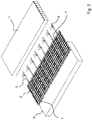
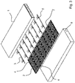
- Fig. 2 , 3 and 4th each show a schematic view of a second embodiment of a riding surface according to the invention, with a tread layer 1 and a mat 2 arranged between floor 8 and tread layer 1 in the sense of a separating mat, with drip hoses 3 in grooves 4 on the side of the mat 2 facing the tread layer 1 Irrigation of the footing 1 are embedded.
- the mat 2 is made of a solid material, namely PVC, and can be plugged together from individual mat elements 2.
- the grooves 4 on the side of the mat 2 facing the footing layer 1 are milled into the mat 2 and each have a width and a depth of 18 mm.
- the grooves 4 and thus the drip hoses 3 are arranged parallel and at equal intervals from one another.
- holes 7 are linearly and parallel to the drip tubes 3, which allow penetration of water and largely avoid penetration of larger amounts of sand and other particles.
- the holes 7 are dimensioned just so large that unwanted amounts of water seep into the footing, for example during heavy rain, but not the amount of water that emerges from the hoses 3 to irrigate the footing.
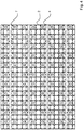
- the mat 2 On its side facing the footing layer 1, the mat 2 has a lattice structure which, on the one hand, contributes to the stability of the mat 2 and, on the other hand, prevents water escaping unintentionally from the pedaling hoses 3 through the holes 7.
- the areas of the drip tubes 3 and those of the holes 7 are separated from one another at least to some extent by a lattice structure.
- the drip hoses 3 are made of plastic and have valves 5 oriented towards the footing 1 at regular intervals for watering the footing 1.
- the drip hoses are dimensioned in such a way that they can ideally be embedded or clamped in the grooves.
- the mat 2 is arranged on a natural ground 8, namely gravel. Due to the water permeability of the mat 2, an optimal drainage of excess water can be realized.
- the footing 1 essentially consists of sand plus aggregates, namely geotextile, and rests on the mat 2. It has a thickness of 10 to 12 cm.
Landscapes
- Engineering & Computer Science (AREA)
- Architecture (AREA)
- Civil Engineering (AREA)
- Structural Engineering (AREA)
- Road Paving Structures (AREA)
- Laminated Bodies (AREA)
- Soil Working Implements (AREA)
- Vehicle Interior And Exterior Ornaments, Soundproofing, And Insulation (AREA)
Abstract
Description
- Die vorliegende Erfindung betrifft einen bewässerbaren Reitboden sowie ein Verfahren zu dessen Bau.
- Aus der Praxis sind Reitböden und Systeme zur Bewässerung von Reitböden in den unterschiedlichsten Ausprägungen sowohl für den freien Reitplatz als auch für die Reithalle bekannt. Insbesondere sind eine Vielzahl an Böden und Systemen bekannt, unter anderem mit einer sogenannten Unterflurbewässerung, die für eine gleichmäßige Durchfeuchtung des Platzes sorgen sollen. Auf dem meist gewachsenen Boden werden Tropfrohre bzw. -schläuche und darüber Bodenraster zum Schutz der Tropfschläuche gegen Beschädigung durch Pferdehufe ausgelegt. Die Bodenraster sind in der Regel gitterförmig aufgebaut, sodass der Sand der Tretschicht be- und ggf. entwässert werden kann. Hierzu werden die Bodenraster mit Sand verfüllt und vollständig überdeckt, um eine Tretschicht zu bilden. Aufgrund der physikalischen Eigenschaften des Sandes, insbesondere aufgrund der Kapillarwirkung der Sandpartikel, wird Feuchtigkeit von den Tropfschläuchen nach oben in die Tretschicht transportiert. Durch die Nutzung eines solchen Reitbodens mit integrierter Befeuchtung wird die Trittfestigkeit unter weitestgehender Eliminierung der Rutschgefahr für das Pferd erhöht. Des Weiteren wird die Zeit für eine separate Befeuchtung des Bodens eingespart. Zur Auflockerung des Bodens werden dem Sand regelmäßig Textil- oder Vlieshäcksel beigemengt.
- Ein wesentliches Problem der aus der Praxis bekannten Reitböden besteht darin, dass die Tropfschläuche unmittelbar auf dem Boden ausgelegt sind und ein nicht unbeachtlicher Teil der Wassermenge nicht etwa die Tretschicht befeuchtet, sondern vielmehr versickert bzw. in den Boden abläuft. Des Weiteren sind die Aussparungen der meist dicken und offenen Bodenraster zur Be- und Entwässerung der Reitböden äußerst groß. Da der Sand nebst Zuschlägen der Tretschicht auch in das Bodenraster verfüllt werden muss, ist eine äußerst große Menge an Sand erforderlich. In anderen Worten ist das mit Sand zu befüllende Volumen der bekannten Bodenraster äußerst groß. Dies erhöht die notwendige Sandmenge. Ein weiterer Nachteil der bekannten Reitböden liegt in ihrem in der Herstellung recht aufwendigen Aufbau, insbesondere bei großflächiger Ausführung. Zudem gestaltet sich die Handhabung beim Lagern, beim Bau und beim Transport des Reitbodens - je nach Größe bzw. Fläche - recht umständlich. Ein weiterer Nachteil besteht darin, dass zur Erzielung eines schockabsorbierenden Bodens bzw. einer geeigneten Dämpfung zur Schonung der Pferde meist entsprechende Zusätze, beispielsweise in Form von Textil- oder Vlieshäcksel, erforderlich sind, in der Wirkung allein jedoch unzureichend.
- Der vorliegenden Erfindung liegt daher die Aufgabe zugrunde, einen Reitboden anzubieten, der bei robuster und einfacher Konstruktion unter weitestgehender Eliminierung der Verletzungsgefahr für das Pferd eine optimale Be- und Entwässerung gewährleistet. Außerdem soll ein verbessertes Verfahren zum Bau eines entsprechenden Reitbodens angegeben werden.
- Voranstehende Aufgabe ist in Bezug auf den Reitboden durch die Merkmale des Anspruchs 1 gelöst. Danach weist der Reitboden eine Tretschicht, eine zwischen Boden und Tretschicht angeordnete Matte und Tropfschläuche auf, wobei die Tropfschläuche in der Matte, vorzugsweise in Nuten auf der der Tretschicht zugewandten Seite der Matte eingebettet sind.
- In Bezug auf das erfindungsgemäße Verfahren ist die zugrundeliegende Aufgabe durch die Merkmale des Anspruchs 13 gelöst, nämlich dadurch, dass die Tropfschläuche in der Matte, vorzugsweise in Nuten auf der der Tretschicht zugewandten Seite der Matte vorzugsweise vor Ort eingebettet werden.
- In erfindungsgemäßer Weise ist erkannt worden, dass es von ganz besonderem Vorteil ist, die Tropfschläuche nicht etwa am Boden anzuordnen und durch in ihrem Aufbau aufwendige und voluminöse Bodenraster zu schützen, die wiederum zum Auffüllen und Abdecken der Bodenraster mit einem großen Volumen an Sand sowie dämpfenden Zusätzen aufgefüllt werden müssen. Ganz im Gegenteil geht die Erfindung einen völlig anderen Weg, wird nämlich unmittelbar oder mittelbar auf den Boden eine Matte ausgelegt und die Tropfschläuche auf der der Tretschicht zugewandten Seite der Matte angeordnet. Im Konkreten können die Tropfschläuche in Nuten auf der der Tretschicht zugewandten Seite der Matte eingebettet sein. Durch die Nuten sind die Tropfschläuche fest auf der Matte angeordnet und weitestgehend vor Beschädigung geschützt und gleichzeitig ein ungewolltes Absickern des aus den Tropfschläuchen gelangendes Wassers vermeidbar. Die Tropfschläuche können der Matte bspw. durch Presspassung zuordenbar sein. Dabei kann es erforderlich sein, die Tropfschläuche per Tritt oder leichtem Hammerschlag in die Matte einzubetten bzw. einzuklemmen. Auch sind ein Rastmechanismus und/oder nut- und/oder federähnliche Ausprägungen denkbar. Die Tretschicht liegt somit unmittelbar oder mittelbar auf der Matte und den Tropfschläuchen auf. Dadurch sind ein äußerst dünner Reitboden und dennoch eine robuste Struktur realisierbar. Das erforderliche Volumen der Tretschicht kann auf ein Minimum reduziert werden. Auch eine etwaige Verletzungsgefahr aufgrund zu tiefer Ausnehmungen von Bodenrastern ist eliminiert. Die Tropfschläuche haben aufgrund der Einbettung in die Nuten der Matte eine feste Position und können während des Aufbaus des Reitbodens oder im Laufe der Zeit nicht ohne Weiteres verrutschen. Ein weiterer Vorteil besteht darin, dass aufgrund des einfachen Aufbaus, insbesondere aufgrund der vordefinierten Einbettung der Tropfschläuche, der Bau des Reitbodens auch ohne besondere Fachkenntnisse erfolgen kann.
- Folglich ist mit dem erfindungsgemäßen Reitboden sowie mit dem Verfahren zum Bau eines erfindungsgemäßen Reitbodens eine Möglichkeit angegeben, bei robuster und einfacher Konstruktion unter weitestgehender Eliminierung der Verletzungsgefahr für das Pferd eine optimale Be- und Entwässerung zu gewährleistet.
- In vorteilhafter Weise ist die Matte zumindest bereichsweise aus einem wasserdurchlässigen und/oder weichen und/oder dämpfenden Material hergestellt. Besonders gut eignet sich hierfür PU-Schaumgummi, welches vorzugsweise unter Hitzeeinwirkung gepresst und/oder gebacken wird. Ebenso denkbar ist die Verwendung von Gummigranulat, insbesondere aus recycelten Autoreifen. Die Matte kann weitestgehend massiv aufgebaut sein oder eine Gitterstruktur aufweisen. Die Ausbildung der Matte aus einem weichen bzw. dämpfenden Material ist besonders gesundheitsfördernd bzw. schonend für Pferde und kann die Beimengung von weichen Zusätzen im Sand ersparen. Eine gewisse Wasserdurchlässigkeit verhindert ein Anstauen von Wasser und eine zu starke Nässe des Reitbodens. Bei einer in sich weitestgehend geschlossenen Matte wird das ungewollte Versickern des zur Befeuchtung dienenden Wassers vermieden, zumindest aber reduziert. Alternativ oder zusätzlich ist die Matte zumindest bereichsweise aus einem festen Material, vorzugsweise aus PVC, hergestellt. Dadurch sind eine erhöhte Stabilität sowie ein erhöhter Schutz der Tropfschläuche gewährleistet. Des Weiteren bringt die Nutzung eines festen Materials den Vorteil einer gewissen Druckverteilung mit sich. Denkbar ist es, dass die Matte zumindest bereichsweise aus wasserundurchlässigem Material hergestellt ist, insbesondere im Bereich der Nuten, um ein ungewolltes Versickern des aus den Tropfschläuchen austretenden Wassers weitestgehend zu vermeiden. Die Matte kann äußerst dünn ausgeführt sein, nämlich gerade so dick, dass ein Schutz und ggf. eine Druckverteilung gewährleistet ist.
- Je nach Material und Herstellungsmethode der Matte ist es für die Lagerung, den Transport und die Handhabung von Vorteil, wenn die Matte als Rollenware bereitstellbar ist. Des Weiteren ist es denkbar, dass einzelne Mattenelemente vor Ort zusammensteckbar und/oder beliebig erweiterbar sind. Somit lässt sich der Reitboden auf beliebige Flächen erweitern, nämlich durch Aneinanderreihen mehrerer Matten und ggf. Zwischenmatten. Dazu könnten an den Enden der Matte Anschlussbereiche zum Anschließen jeweils einer weiteren Matte ausgebildet sein. Ein einfaches Aneinanderlegen und/oder Überlappen mehrerer Matten ist ebenso denkbar. Eine außenliegende Matte könnte per Zuschnitt angepasst werden. Bereits eine Dicke der Matte von 25 mm bis 30 mm ist ausreichend, um die Tropfschläuche in die Matte einzubetten und eine stabile und dämpfende Grundlage für die Tretschicht zu bilden. Extrem hohe Bodenstrukturen, wie sie aus der Praxis beim Bau von Reitböden mit Bodenrastern bekannt sind, können entfallen.
- Von weiterem Vorteil ist es, wenn die Nuten in der Matte eingefräst und/oder bei Herstellung der Matte insbesondere spritzgusstechnisch hergestellt sind. Dabei können Breite und Tiefe der Nuten an die verwendeten Schläuche angepasst werden. Bevorzugt verlaufen die Nuten zur Einbettung der Tropfschläuche in regelmäßigen Abständen und parallel zueinander. Abstände von 30 cm zwischen den Tropfschläuchen sind denkbar.
- Insbesondere bei wasserdurchlässigen Matten kann ein Teil des aus den Tropfschläuchen austretenden Wassers durch die Matte hindurch versickern und bleibt für die Bewässerung ungenutzt. Um dies zu vermeiden ist in weiter vorteilhafter Weise zumindest die zur Tretschicht hin orientierte Oberfläche der Nuten weitestgehend wasserundurchlässig, insbesondere mit einem wasserundurchlässigen Material beschichtet und/oder die Nuten in einer wasserundurchlässigen Matte oder zumindest einem wasserundurchlässigen Bereich der Matte ausgebildet.
- In besonders vorteilhafter Weise weist die Matte in bestimmten Abständen Durchgänge, vorzugsweise Löcher, auf, die ein Durchdringen von Wasser zulassen und/oder ein Durchdringen größerer Mengen Sand und anderen Partikeln weitestgehend vermeiden. Dadurch kann ein Entwässern bspw. bei Starkregen gewährleistet werden, ohne Wasser, welches aus den Tropfschläuchen kommt, zu verlieren. Gleichzeitig versickert in idealer Weise nahezu kein Sand aus der Tretschicht nach unterhalb der Matte. Denkbar ist eine runde und/oder quadratische Ausgestaltung der Durchgänge. Dabei ist es denkbar, dass die Durchgänge linienförmig und parallel zu den Nuten angeordnet sind und einen gewissen Abstand zu den Nuten aufweisen, sodass das aus den Tropfschläuchen gelangendes Wasser zumindest weitestgehend nicht durch die Durchgänge versickert.
- Um ein Verrutschen des Sandes der Tretschicht zu vermeiden, ist es von besonderem Vorteil, wenn die Matte zumindest auf ihrer die Tretschicht zugewandten Seite eine Struktur, insbesondere eine Netz- oder Gitterstruktur aufweist. Eine entsprechende Struktur der Oberfläche der Matte kann zudem abermals verhindern, dass das aus den Tropfschläuchen austretende Wasser durch die Durchgänge versickert, bspw. indem die Nuten und die Durchgänge in unterschiedlichen Vertiefungen angeordnet sind bzw. durch Erhöhungen einer Struktur zumindest bereichsweise voneinander getrennt sind. Wichtig hierbei ist, dass das aus den Tropfschläuchen gelangende Wasser nicht wieder direkt über die Durchgänge versickert, sondern vielmehr in die Tretschicht gelangt. Die Durchgänge sollen verhindern, dass sich eine übermäßige Menge an Wasser in der Tretschicht befindet, und diese nach unterhalb der Trennschicht abführen.
- In weiter vorteilhafter Weise weisen die vorzugsweise aus Kunststoff hergestellten Tropfschläuche zur Bewässerung des Tretbodens zur Tretschicht hin orientierte Ventile und/oder Membrane auf. Diese liegen somit im eingebetteten Zustand der Tretschläuche nach oben hin orientiert. Hierdurch ist ein idealer Transport der Feuchtigkeit zur Tretschicht hin realisierbar. Denkbar ist ein Durchmesser der Tropfschläuche von 16 mm. Bevorzugt werden die Tropfschläuche in regelmäßigen Abständen, bspw. parallel zueinander, angeordnet.
- Für eine erhöhte Stabilisierung und einen erhöhten Schutz der Tretschläuche, sowie zur Druckverteilung ist es denkbar zwischen der Matte und der Tretschicht eine vorzugsweise aus PVC hergestellte Zwischenmatte und/oder ein Zwischennetz anzuordnen. Eine Zwischenmatte bzw. ein Zwischennetz kann in vorteilhafter Weise in bestimmten Abständen Durchgänge, vorzugsweise Löcher, aufweisen. Diese Durchgänge können ein Durchdringen von Wasser von den Tropfschläuchen zu der Tretschicht hin zulassen, jedoch ein Durchdringen größerer Mengen Sand und anderer Partikel von der Tretschicht nach unterhalb der Zwischenschicht vermeiden. Ein für die Bewässerung der Tretschicht optimaler Abstand zwischen den einzelnen Durchgängen und ggf. Membranen einer Zwischenmatte ist 10 cm. Um ein Verrutschen des Sandes der Tretschicht zu vermeiden, ist es denkbar, dass die Zwischenmatte zumindest auf ihrer die Tretschicht zugewandten Seite eine Struktur, insbesondere eine Netz- oder Gitterstruktur aufweist. Die Zwischenmatte kann äußerst dünn ausgeführt sein, nämlich gerade so dick, dass ein Schutz und ggf. eine Druckverteilung gewährleistet ist.
- Des Weiteren ist es denkbar, dass die Matte unmittelbar oder mittelbar auf gewachsenem Boden und/oder einer Drainage, insbesondere Schotter, angeordnet ist. Die Matte kann trotz ihrer geringen Dicke derart robust ausgebildet sein, dass sie auch einem groben Untergrund standhält, gewisse Bodenunebenheiten gar ausgleicht.
- Des Weiteren ist es denkbar, dass die Matte auf gewachsenem Boden und/oder einer Drainage, insbesondere Schotter, angeordnet ist. Die Matte kann trotz ihrer geringen Dicke derart robust ausgebildet sein, dass sie auch einem groben Untergrund standhält, gewisse Bodenunebenheiten gar ausgleicht.
- Die Tretschicht besteht in vorteilhafter Weise im Wesentlichen aus Sand nebst Zuschlägen, insbesondere aus Geotextil, und liegt unmittelbar oder mittelbar auf der Matte und den Tropfschläuchen auf. Ein Verfüllen und Abdecken eines volumenreichen Bodenrasters ist hier nicht erforderlich. Die Tretschicht weist in vorteilhafter Weise eine Dicke von 10 bis 12 cm auf, um ein optimales Befeuchten der Tretschicht und ein verringertes Verletzungsrisiko für Pferd und Reiter zu gewährleisten.
- Des Weiteren ist es denkbar, dass unterhalb der Matte eine Schutzmatte angeordnet ist, die aus einem wasserdurchlässigen und/oder weichen und/oder dämpfenden Material hergestellt ist. Besonders gut eignet sich hierfür PU-Schaumgummi, welches vorzugsweise unter Hitzeeinwirkung gepresst und/oder gebacken wird. Ebenso denkbar ist die Verwendung von Gummigranulat, insbesondere aus recycelten Autoreifen. Die Schutzmatte kann weitestgehend massiv aufgebaut sein oder eine Gitterstruktur aufweisen. Die Ausbildung der Schutzmatte aus einem weichen bzw. dämpfenden Material ist besonders gesundheitsfördernd bzw. schonend für Pferde und kann die Beimengung von weichen Zusätzen im Sand zu einem gewissen Grad abermals ersparen.
- Grundgesetzlich ist es denkbar, dass in den Reitboden, insbesondere in die Tretschicht, Feuchtigkeitssensoren/ -fühler integriert sind, die die Feuchtigkeit der Tretschicht messen. Eine Steuerung kann die Menge und/oder die Zeit der Wasserzufuhr über die Tropfschläuche regeln.
- Der erfindungsgemäße Reitboden sowie das erfindungsgemäße Verfahren zum Aufbau eines solchen Reitbodens eignet sich für alle Anwendungsbereiche, einschließlich Reithallen, Reitplätze im Freien und Rennbahnen. Selbst überhöhte Kurven, wie beispielsweise bei Rennbahnen sind mit dem erfindungsgemäßen Reitboden sowie dem erfindungsgemäßen Verfahren realisierbar.
- Es gibt nun verschiedene Möglichkeiten, die Lehre der vorliegenden Erfindung in vorteilhafter Weise auszugestalten und weiterzubilden. Dazu ist einerseits auf die dem Anspruch 1 nachgeordneten Ansprüche und andererseits auf die nachfolgende Erläuterung zweier bevorzugter Ausführungsbeispiele der Erfindung anhand der Zeichnung zu verweisen. In Verbindung mit der Erläuterung der bevorzugten Ausführungsbeispiele der Erfindung anhand der Zeichnung werden auch im Allgemeinen bevorzugte Ausgestaltungen und Weiterbildungen der Lehre erläutert. In der Zeichnung zeigt
- Fig. 1
- in einer schematischen Ansicht ein erstes Ausführungsbeispiel des Aufbaus eines erfindungsgemäßen Reitbodens.
- Fig. 2
- in einer schematischen Ansicht ein zweites Ausführungsbeispiel des Aufbaus eines erfindungsgemäßen Reitbodens,
- Fig. 3
- in Explosionsansicht den Gegenstand aus
Fig. 2 und - Fig. 4
- eine Draufsicht der Matte aus den
Figuren 2 und3 . -
Fig. 1 zeigt in einer schematischen Ansicht ein erstes Ausführungsbeispiel des Aufbaus eines erfindungsgemäßen Reitbodens, mit einer Tretschicht 1, einer zwischen Boden und Tretschicht 1 angeordneten Matte 2, hier unteren Matte 2 genannt, und Tropfschläuchen 3, die in Nuten 4 der der Tretschicht 1 zugewandten Seite der unteren Matte 2 eingebettet sind. - Die untere Matte 2 ist aus einem wasserdurchlässigen, weichen und dämpfenden Material, nämlich aus PU-Schaumgummi hergestellt. Die dämpfende Eigenschaft der Matte 2 ist ganz besonders gesundheitsfördernd für die sich auf dem Reitboden bewegenden Pferde. Denkbar ist hier auch die Herstellung der unteren Matte 2 aus einem Gummi-Granulat aus recycelten Autoreifen. Die untere Matte 2 ist als Rollenware bereitstellbar, wobei die einzelnen Rollbahnen der unteren Matte 2 zusammensteckbar und beliebig erweiterbar sind. Die Dicke der unteren Matte 2 beträgt in etwa 25 bis 30 mm. Sie ist auf einem in der
Fig. 1 nicht gezeigten, vorzugsweise gewachsenen Boden und/oder einer Drainage, bspw. Schotter, anordenbar. Durch die Wasserdurchlässigkeit der unteren Matte 2 ist ein optimales Abfließen von überschüssigem Wasser realisierbar. Das weiche und dennoch stabile Material der unteren Matte 2 bietet einen idealen Grund für den Reitboden, auch auf gröberem Boden. - Die Tropfschläuche 3 sind aus Kunststoff hergestellt und weisen in regelmäßigen Abständen zur Bewässerung des Tretbodens zur Tretschicht hin orientierte Ventile 5 auf. Die Tropfschläuche können einen Durchmesser von 16 mm haben und sind in parallelen Bahnen in die untere Matte 2 eingebettet.
- Oberhalb der unteren Matte 2 und den Tropfschläuchen 3 ist zur Stabilisierung und zum Schutz der Tropfschläuche 3 sowie zur Druckverteilung zwischen der unteren Matte 2 und der Tretschicht 1 eine aus PVC hergestellte Zwischenmatte 6 angeordnet. Die Zwischenmatte 6 weist mehrere, mit 10 cm Abstand zueinander angeordnete Löcher 7 auf. Diese Löcher 7 lassen ein Durchdringen von Wasser von unterhalb der Zwischenmatte 6 zu der Tretschicht 1 zu, vermeiden jedoch ein Durchdringen größerer Mengen Sand und anderer Partikel von der Tretschicht 1 nach unterhalb der Zwischenmatte 6. Auf der der Tretschicht 1 zugewandten Seite der Zwischenmatte 6 weist die Zwischenmatte 6 eine Gitterstruktur auf, die ein Verrutschen der Tretschicht vermeidet. Anstelle einer Zwischenmatte 6 ist auch ein Zwischennetz denkbar.
- Die Tretschicht 1 besteht im Wesentlichen aus Sand nebst Zuschlägen, nämlich aus Geotextil und liegt auf der Zwischenmatte 6 auf. Sie weist eine Dicke von 10 bis 12 cm auf.
-
Fig. 2 ,3 und4 zeigen jeweils in einer schematischen Ansicht ein zweites Ausführungsbeispiel eines erfindungsgemäßen Reitbodens, mit einer Tretschicht 1 und einer zwischen Boden 8 und Tretschicht 1 angeordneten Matte 2 im Sinne einer Trennmatte, wobei in Nuten 4 auf der der Tretschicht 1 zugewandten Seite der Matte 2 Tropfschläuche 3 zur Bewässerung der Tretschicht 1 eingebettet sind. - Die Matte 2 ist aus einem festen Material, nämlich aus PVC hergestellt und aus einzelnen Mattenelementen 2 zusammensteckbar. Die Nuten 4 auf der der Tretschicht 1 zugewandten Seite der Matte 2 sind in die Matte 2 eingefräst und weisen eine Breite sowie eine Tiefe von jeweils 18 mm auf. Die Nuten 4 und somit die Tropfschläuche 3 sind parallel und in gleichen Abständen zueinander angeordnet.
- Zwischen den Tropfschläuchen 3 sind linienförmig und parallel zu den Tropfschläuchen 3 quadratische Löcher 7 vorgesehen, die ein Durchdringen von Wasser zulassen und ein Durchdringen von größeren Mengen Sand und anderen Partikeln weitestgehend vermeiden. Die Löcher 7 sind gerade so groß dimensioniert, dass ungewollte Wassermengen in der Tretschicht versickern, bspw. bei Starkregen, nicht jedoch die zur Bewässerung der Tretschicht aus den Tretschläuchen 3 tretende Wassermenge.
- Die Matte 2 weist auf ihrer die Tretschicht 1 zugewandten Seite eine Gitterstruktur auf, die zum einen zur Stabilität der Matte 2 beiträgt und zum anderen verhindert, dass ungewollter Weise aus den Tretschläuchen 3 tretendes Wasser durch die Löcher 7 absickert. In anderen Worten sind die Bereiche der Tropfschläuche 3 und die der Löcher 7 durch eine Gitterstruktur zumindest ein Stück weit voneinander getrennt.
- Die Tropfschläuche 3 sind aus Kunststoff hergestellt und weisen in regelmäßigen Abständen zur Bewässerung der Tretschicht 1 zur Tretschicht 1 hin orientierte Ventile 5 auf. Die Tropfschläuche sind derart dimensioniert, dass sie in idealer Weise in die Nuten einbettbar bzw. klemmbar sind.
- Die Matte 2 ist auf einem gewachsenen Boden 8, nämlich Schotter angeordnet. Durch die Wasserdurchlässigkeit der Matte 2 ist ein optimales Abfließen von überschüssigem Wasser realisierbar.
- Die Tretschicht 1 besteht im Wesentlichen aus Sand nebst Zuschlägen, nämlich aus Geotextil und liegt auf der Matte 2 auf. Sie weist eine Dicke von 10 bis 12 cm auf.
- Hinsichtlich weiterer vorteilhafter Ausgestaltungen des erfindungsgemäßen Reitbodens und des Verfahrens zum Bau eines Reitbodens wird zur Vermeidung von Wiederholungen auf den allgemeinen Teil der Beschreibung sowie auf die beigefügten Ansprüche verwiesen.
- Schließlich sei ausdrücklich darauf hingewiesen, dass die voranstehend beschriebenen Ausführungsbeispiele des erfindungsgemäßen Reitbodens und des Verfahrens zum Bau eines Reitbodens lediglich zur Erörterung der beanspruchten Lehre dienen, diese jedoch nicht auf die Ausführungsbeispiele einschränken.
-
- 1
- Tretschicht
- 2
- (Untere) Matte
- 3
- Tropfschläuche
- 4
- Nuten
- 5
- Ventile
- 6
- Zwischenmatte
- 7
- Löcher
- 8
- Boden/Schotter
Claims (13)
- Reitboden, mit einer Tretschicht (1) und einer zwischen Boden und Tretschicht (1) angeordneten Matte (2), wobei in der Matte (2), vorzugsweise in Nuten (4) auf der der Tretschicht (1) zugewandten Seite der Matte (2), Tropfschläuche (3) zur Bewässerung der Tretschicht eingebettet sind.
- Reitboden nach Anspruch 1, dadurch gekennzeichnet, dass die Matte (2) zumindest bereichsweise aus einem wasserdurchlässigen und/oder weichen und/oder dämpfenden Material, vorzugsweise aus PU-Schaumgummi und/oder Gummi-Granulat, insbesondere aus recycelten Autoreifen, und/oder aus einem festen Material, vorzugsweise aus PVC hergestellt ist.
- Reitboden nach Anspruch 1 oder 2, dadurch gekennzeichnet, dass die Matte (2) als Rollenware bereitstellbar ist und/oder einzelne Mattenelemente (2) zusammensteckbar sind.
- Reitboden nach einem der Ansprüche 1 bis 3, dadurch gekennzeichnet, dass die Nuten (4) in die Matte (2) eingefräst und/oder bei Herstellung der Matte (2) insbesondere spritzgusstechnisch hergestellt sind.
- Reitboden nach einem der Ansprüche 1 bis 4, dadurch gekennzeichnet, dass die Nuten (4) weitestgehend wasserundurchlässig sind, insbesondere mit einem wasserundurchlässigen Material beschichtet und/oder die Nuten in einem wasserundurchlässigem Material ausgebildet sind.
- Reitboden nach einem der Ansprüche 1 bis 5, dadurch gekennzeichnet, dass die Matte (2) Durchgänge, vorzugsweise Löcher (7) aufweist, die ein Durchdringen von Wasser zulassen und/oder ein Durchdringen von größeren Mengen Sand und anderen Partikeln weitestgehend vermeiden.
- Reitboden nach einem der Ansprüche 1 bis 6, dadurch gekennzeichnet, dass die Matte (2) zumindest auf ihrer die Tretschicht (1) zugewandten Seite eine Struktur, insbesondere eine Netz- oder Gitterstruktur, aufweist.
- Reitboden nach einem der Ansprüche 1 bis 7, dadurch gekennzeichnet, dass die vorzugsweise aus Kunststoff hergestellten Tropfschläuche (3) zur Tretschicht (1) hin orientierte Ventile und/oder Membrane (5) für den Wasseraustritt aufweisen.
- Reitboden nach einem der Ansprüche 1 bis 3, dadurch gekennzeichnet, dass zur Stabilisierung und zum Schutz der Tropfschläuche (3) und/oder zur Druckverteilung zwischen der Matte (2) und der Tretschicht (1) eine vorzugsweise aus PVC hergestellte Zwischenmatte (6) und/oder ein Zwischennetz angeordnet ist.
- Reitboden nach einem der Ansprüche 1 bis 9, dadurch gekennzeichnet, dass der Reitboden, insbesondere die Matte (2), auf gewachsenem Boden (8) und/oder einer Drainage, insbesondere Schotter (8), anordenbar ist.
- Reitboden nach einem der Ansprüche 1 bis 10, dadurch gekennzeichnet, dass die Tretschicht (1) im Wesentlichen aus Sand nebst Zuschlägen insbesondere aus Geotextil besteht und unmittelbar oder mittelbar auf der Matte (2) und den Tropfschläuchen (3) aufliegt.
- Reitboden nach einem der Ansprüche 1 bis 11, dadurch gekennzeichnet, dass unterhalb der Matte (2) eine Schutzmatte angeordnet ist, die aus einem wasserdurchlässigen und/oder weichen und/oder dämpfenden Material, vorzugsweise aus PU-Schaumgummi und/oder Gummi-Granulat, insbesondere aus recycelten Autoreifen, hergestellt ist.
- Verfahren zum Bau eines Reitbodens nach einem der Ansprüche 1 bis 12, mit einer Tretschicht (1), einer zwischen Boden und Tretschicht (1) angeordneten Matte (2) und Tropfschläuchen (3), wobei die Tropfschläuche (3) in der Matte (2), vorzugsweise in Nuten (4) auf der der Tretschicht (1) zugewandten Seite der Matte (2), eingebettet werden.
Applications Claiming Priority (5)
| Application Number | Priority Date | Filing Date | Title |
|---|---|---|---|
| DE102017201564 | 2017-01-31 | ||
| DE102017202251.5A DE102017202251A1 (de) | 2017-01-31 | 2017-02-13 | Reitboden und Verfahren zum Bau eines Reitbodens |
| DE102017212824.0A DE102017212824A1 (de) | 2017-07-26 | 2017-07-26 | Reitboden und Verfahren zum Bau eines Reitbodens |
| PCT/DE2017/200140 WO2018141321A1 (de) | 2017-01-31 | 2017-12-28 | Reitboden und verfahren zum bau eines reitbodens |
| EP17840587.4A EP3374567B2 (de) | 2017-01-31 | 2017-12-28 | Reitboden und verfahren zum bau eines reitbodens |
Related Parent Applications (2)
| Application Number | Title | Priority Date | Filing Date |
|---|---|---|---|
| EP17840587.4A Division EP3374567B2 (de) | 2017-01-31 | 2017-12-28 | Reitboden und verfahren zum bau eines reitbodens |
| EP17840587.4A Division-Into EP3374567B2 (de) | 2017-01-31 | 2017-12-28 | Reitboden und verfahren zum bau eines reitbodens |
Publications (2)
| Publication Number | Publication Date |
|---|---|
| EP3763876A1 true EP3763876A1 (de) | 2021-01-13 |
| EP3763876B1 EP3763876B1 (de) | 2022-09-07 |
Family
ID=63040267
Family Applications (2)
| Application Number | Title | Priority Date | Filing Date |
|---|---|---|---|
| EP17840587.4A Active EP3374567B2 (de) | 2017-01-31 | 2017-12-28 | Reitboden und verfahren zum bau eines reitbodens |
| EP20188835.1A Active EP3763876B1 (de) | 2017-01-31 | 2017-12-28 | Reitboden und verfahren zum bau eines reitbodens |
Family Applications Before (1)
| Application Number | Title | Priority Date | Filing Date |
|---|---|---|---|
| EP17840587.4A Active EP3374567B2 (de) | 2017-01-31 | 2017-12-28 | Reitboden und verfahren zum bau eines reitbodens |
Country Status (11)
| Country | Link |
|---|---|
| US (2) | US20190390414A1 (de) |
| EP (2) | EP3374567B2 (de) |
| JP (1) | JP7252124B2 (de) |
| CN (1) | CN110214211A (de) |
| AU (1) | AU2017396836A1 (de) |
| CA (1) | CA3051716C (de) |
| DK (2) | DK3374567T4 (de) |
| ES (2) | ES2932303T3 (de) |
| RU (1) | RU2019125972A (de) |
| WO (1) | WO2018141321A1 (de) |
| ZA (1) | ZA201905091B (de) |
Families Citing this family (5)
| Publication number | Priority date | Publication date | Assignee | Title |
|---|---|---|---|---|
| RU2019125972A (ru) | 2017-01-31 | 2021-03-02 | Вольфганг БАХЕР | Поверхность для верховой езды и способ конструирования поверхности для верховой езды |
| US11746476B2 (en) * | 2019-11-25 | 2023-09-05 | Capillary Concrete, Llc | Subsurface irrigation system for a sports field |
| US12492517B2 (en) * | 2022-08-12 | 2025-12-09 | Capillary Concrete, Llc | Equestrian arena surface filtration system and related methods |
| DE202023103154U1 (de) | 2023-06-07 | 2023-11-28 | terra-bausysteme GmbH | Reitboden |
| DE102023115033A1 (de) | 2023-06-07 | 2024-12-12 | terra-bausysteme GmbH | Schichtboden |
Citations (5)
| Publication number | Priority date | Publication date | Assignee | Title |
|---|---|---|---|---|
| JPH09203007A (ja) * | 1995-11-21 | 1997-08-05 | Sumitomo Rubber Ind Ltd | 舗装構造 |
| WO2000062603A1 (en) * | 1999-04-19 | 2000-10-26 | Kent Mudge | A matting suitable for use as a floor/wall covering |
| JP2005348669A (ja) * | 2004-06-11 | 2005-12-22 | Gurooben Kk | 人工土壌構造 |
| DE102005023413A1 (de) * | 2005-05-21 | 2006-11-23 | Willibald Hergeth | Bodenplatte und Decke |
| WO2009075587A1 (en) * | 2007-12-13 | 2009-06-18 | Oldroyd Systemer As | Drainage system and method for installation of drainage system |
Family Cites Families (32)
| Publication number | Priority date | Publication date | Assignee | Title |
|---|---|---|---|---|
| US770888A (en) | 1902-11-29 | 1904-09-27 | Int Harvester Co | Husking-roll. |
| US4489115A (en) * | 1983-02-16 | 1984-12-18 | Superturf, Inc. | Synthetic turf seam system |
| SU1308280A1 (ru) | 1985-12-23 | 1987-05-07 | О.П.Герейш | Подстилочный коврик |
| JPS63171818A (ja) | 1987-01-09 | 1988-07-15 | Nkk Corp | 酸素高炉の羽口 |
| JPH086807Y2 (ja) * | 1991-09-11 | 1996-02-28 | 有限会社クリーン・アップ・システム | 排水、保水装置 |
| DE9405829U1 (de) | 1993-09-02 | 1994-06-23 | Otto, Werner, 90518 Altdorf | Bodenbefestigungsmatte |
| DE4416943C2 (de) | 1994-05-13 | 1997-01-23 | Funke Kunststoffe Gmbh | Aufbau einer Bewegungsfläche für Pferde, insbesondere für einen Reitplatz |
| US5938372A (en) * | 1997-03-05 | 1999-08-17 | Lichfield; William H. | Subsurface irrigation apparatus and method |
| BE1011763A3 (nl) | 1998-02-25 | 1999-12-07 | E C C Naamloze Vennootschap | Bodemlaag. |
| AU2002328220B2 (en) * | 2001-09-21 | 2006-10-12 | Fieldturf Tarkett Inc. | Artificial surface with integrated thermal regulation |
| US7758281B2 (en) * | 2004-07-08 | 2010-07-20 | General Sports Venue Llc | Synthetic sports turf having improved playability and wearability |
| US7290958B2 (en) * | 2004-12-03 | 2007-11-06 | Airfield Systems, Llc | Subsurface drainage system and drain structure therefor |
| US20070144065A1 (en) | 2005-12-27 | 2007-06-28 | Lowe Jerry B | Irrigation mat and plant seeding mat system |
| US7578635B2 (en) * | 2006-10-23 | 2009-08-25 | Airfield Systems, L.L.C. | Subsurface drainage system and method of installing the same |
| DE102006052286B4 (de) | 2006-11-03 | 2009-05-28 | Hit Hinrichs Innovation + Technik Gmbh | Bodengitter |
| DE102007036018B4 (de) | 2007-07-30 | 2012-04-19 | Igg Internationale Geotextil Gmbh | Bewässerungsmatte zur großflächigen Verteilung von Wasser |
| JP3139880U (ja) * | 2007-12-18 | 2008-03-06 | フジインテック株式会社 | 屋内馬場等の散水装置 |
| DE202008006572U1 (de) | 2008-05-14 | 2008-08-21 | Hoser, Ingolf | Reitplatz mit Unterflur-Bewässerungssystem |
| US7993729B2 (en) * | 2008-10-27 | 2011-08-09 | Ronald Wise | Substrate for artificial turf |
| CN201801798U (zh) * | 2010-09-01 | 2011-04-20 | 四川省瑞云环境绿化工程有限公司 | 基于柔性运动场地的给水排水系统 |
| JP2012085549A (ja) | 2010-10-18 | 2012-05-10 | Clear System Co Ltd | 吸排水マットとそれを用いた植物植栽機構と排水機構 |
| EP2599916B1 (de) * | 2011-11-29 | 2015-11-25 | Werner Otto | Reit- oder Sportplatzboden und Verfahren zu Herstellung dessen |
| FR2985882B1 (fr) | 2012-01-20 | 2015-01-02 | Mbd Texinov | Complexe textile d'irrigation |
| US9161496B2 (en) * | 2013-01-04 | 2015-10-20 | Wayne Holland, JR. | Moisture control grid |
| CN203708874U (zh) * | 2013-12-27 | 2014-07-16 | 贵州科农生态环保科技有限责任公司 | 带灌溉系统的喀斯特地区护坡植生结构 |
| DE202014001564U1 (de) | 2014-02-24 | 2014-05-12 | Science To Business Gmbh - Hochschule Osnabrück | Reitplatz mit Unterflur-Be- und Entwässerungssystem |
| JP6411273B2 (ja) * | 2015-04-03 | 2018-10-24 | 株式会社ブリヂストン | 敷設用ユニットおよび踏面構造体 |
| US9668433B2 (en) * | 2015-04-08 | 2017-06-06 | Carlos Alfredo Pujadas | Sub-surface irrigation system and method |
| DE202015003767U1 (de) † | 2015-05-28 | 2016-08-30 | Volker Kormann | Bodenbefeuchtungsanlage |
| AU2016329447A1 (en) * | 2015-10-02 | 2018-03-22 | Capillary Concrete, Llc | Sub-surface irrigation system |
| CN106149510A (zh) * | 2016-07-29 | 2016-11-23 | 艾奇达(上海)建设工程有限公司 | 一种纤维丝、无纺布、石英砂混合马术运动场地面 |
| RU2019125972A (ru) † | 2017-01-31 | 2021-03-02 | Вольфганг БАХЕР | Поверхность для верховой езды и способ конструирования поверхности для верховой езды |
-
2017
- 2017-12-28 RU RU2019125972A patent/RU2019125972A/ru unknown
- 2017-12-28 ES ES20188835T patent/ES2932303T3/es active Active
- 2017-12-28 EP EP17840587.4A patent/EP3374567B2/de active Active
- 2017-12-28 DK DK17840587.4T patent/DK3374567T4/da active
- 2017-12-28 EP EP20188835.1A patent/EP3763876B1/de active Active
- 2017-12-28 ES ES17840587T patent/ES2827480T5/es active Active
- 2017-12-28 JP JP2019537383A patent/JP7252124B2/ja active Active
- 2017-12-28 CN CN201780084781.9A patent/CN110214211A/zh active Pending
- 2017-12-28 AU AU2017396836A patent/AU2017396836A1/en not_active Abandoned
- 2017-12-28 CA CA3051716A patent/CA3051716C/en active Active
- 2017-12-28 DK DK20188835.1T patent/DK3763876T3/da active
- 2017-12-28 US US16/482,130 patent/US20190390414A1/en not_active Abandoned
- 2017-12-28 WO PCT/DE2017/200140 patent/WO2018141321A1/de not_active Ceased
-
2019
- 2019-07-31 ZA ZA2019/05091A patent/ZA201905091B/en unknown
-
2021
- 2021-12-20 US US17/556,005 patent/US12209367B2/en active Active
Patent Citations (5)
| Publication number | Priority date | Publication date | Assignee | Title |
|---|---|---|---|---|
| JPH09203007A (ja) * | 1995-11-21 | 1997-08-05 | Sumitomo Rubber Ind Ltd | 舗装構造 |
| WO2000062603A1 (en) * | 1999-04-19 | 2000-10-26 | Kent Mudge | A matting suitable for use as a floor/wall covering |
| JP2005348669A (ja) * | 2004-06-11 | 2005-12-22 | Gurooben Kk | 人工土壌構造 |
| DE102005023413A1 (de) * | 2005-05-21 | 2006-11-23 | Willibald Hergeth | Bodenplatte und Decke |
| WO2009075587A1 (en) * | 2007-12-13 | 2009-06-18 | Oldroyd Systemer As | Drainage system and method for installation of drainage system |
Also Published As
| Publication number | Publication date |
|---|---|
| CN110214211A (zh) | 2019-09-06 |
| US20220112667A1 (en) | 2022-04-14 |
| EP3374567A1 (de) | 2018-09-19 |
| CA3051716C (en) | 2023-03-28 |
| DK3374567T3 (da) | 2020-11-09 |
| DK3374567T4 (da) | 2023-11-13 |
| RU2019125972A3 (de) | 2021-03-02 |
| EP3763876B1 (de) | 2022-09-07 |
| ES2827480T3 (es) | 2021-05-21 |
| WO2018141321A1 (de) | 2018-08-09 |
| JP7252124B2 (ja) | 2023-04-04 |
| DK3763876T3 (da) | 2022-11-21 |
| RU2019125972A (ru) | 2021-03-02 |
| ES2827480T5 (es) | 2024-03-26 |
| ZA201905091B (en) | 2022-12-21 |
| US12209367B2 (en) | 2025-01-28 |
| AU2017396836A1 (en) | 2019-08-08 |
| CA3051716A1 (en) | 2018-08-09 |
| JP2020505532A (ja) | 2020-02-20 |
| US20190390414A1 (en) | 2019-12-26 |
| EP3374567B2 (de) | 2023-08-16 |
| EP3374567B1 (de) | 2020-08-05 |
| ES2932303T3 (es) | 2023-01-17 |
Similar Documents
| Publication | Publication Date | Title |
|---|---|---|
| EP3374567B1 (de) | Reitboden und verfahren zum bau eines reitbodens | |
| DE3018830C2 (de) | Flachdachbelag | |
| DE2825628A1 (de) | Bodenmatte fuer staende | |
| EP2599916B1 (de) | Reit- oder Sportplatzboden und Verfahren zu Herstellung dessen | |
| DE3630417C2 (de) | ||
| DE202017005493U1 (de) | Reit- oder Sportplatzboden | |
| DE2265298C3 (de) | Wasserspeichernder Bodenschichtaufbau für Vegetationsflächen | |
| DE202014001564U1 (de) | Reitplatz mit Unterflur-Be- und Entwässerungssystem | |
| DE8112126U1 (de) | Matte, insbesondere als Unterbauschicht für einen künstlichen Rasen | |
| EP1422344A1 (de) | Schichtaufbau und Verfahren zu dessen Herstellung | |
| DE102019103473A1 (de) | Wabenförmiger Bodenbelag | |
| DE202016002910U1 (de) | Bewässerungseinrichtung für Vegetationstragschichten | |
| WO2011107114A1 (de) | Reit- oder sportplatz mit drainage und unterflurbewässerung | |
| DE2637987A1 (de) | Abdeckung zum begruenen von boeschungen und daechern | |
| DE3814142A1 (de) | Tragschicht fuer die dachbegruenung | |
| DE102017202251A1 (de) | Reitboden und Verfahren zum Bau eines Reitbodens | |
| DE10038534C2 (de) | Unterbau für Sportplätze, insbesondere Reitplätze | |
| DE3835880A1 (de) | Elastische matte fuer bodenbelaege von sport- und freizeitflaechen | |
| DE102017212824A1 (de) | Reitboden und Verfahren zum Bau eines Reitbodens | |
| AT353049B (de) | Gitterstein fuer stallboeden | |
| EP1249538A2 (de) | Kunststein aus gebrochenen Natursteinen und mit Polyurethanbindung | |
| DE202017105387U1 (de) | Bodenmattenanordnung für Reitplätze | |
| WO2010105835A2 (de) | Belagskonstruktion | |
| DE102023115033A1 (de) | Schichtboden | |
| DE102016204798A1 (de) | Reitboden, Gitterstruktur zum Einbau in einen Reitboden und Verfahren zum Bau eines Reitbodens |
Legal Events
| Date | Code | Title | Description |
|---|---|---|---|
| PUAI | Public reference made under article 153(3) epc to a published international application that has entered the european phase |
Free format text: ORIGINAL CODE: 0009012 |
|
| STAA | Information on the status of an ep patent application or granted ep patent |
Free format text: STATUS: THE APPLICATION HAS BEEN PUBLISHED |
|
| AC | Divisional application: reference to earlier application |
Ref document number: 3374567 Country of ref document: EP Kind code of ref document: P |
|
| AK | Designated contracting states |
Kind code of ref document: A1 Designated state(s): AL AT BE BG CH CY CZ DE DK EE ES FI FR GB GR HR HU IE IS IT LI LT LU LV MC MK MT NL NO PL PT RO RS SE SI SK SM TR |
|
| STAA | Information on the status of an ep patent application or granted ep patent |
Free format text: STATUS: REQUEST FOR EXAMINATION WAS MADE |
|
| 17P | Request for examination filed |
Effective date: 20210713 |
|
| RBV | Designated contracting states (corrected) |
Designated state(s): AL AT BE BG CH CY CZ DE DK EE ES FI FR GB GR HR HU IE IS IT LI LT LU LV MC MK MT NL NO PL PT RO RS SE SI SK SM TR |
|
| GRAP | Despatch of communication of intention to grant a patent |
Free format text: ORIGINAL CODE: EPIDOSNIGR1 |
|
| STAA | Information on the status of an ep patent application or granted ep patent |
Free format text: STATUS: GRANT OF PATENT IS INTENDED |
|
| INTG | Intention to grant announced |
Effective date: 20220413 |
|
| GRAS | Grant fee paid |
Free format text: ORIGINAL CODE: EPIDOSNIGR3 |
|
| GRAA | (expected) grant |
Free format text: ORIGINAL CODE: 0009210 |
|
| STAA | Information on the status of an ep patent application or granted ep patent |
Free format text: STATUS: THE PATENT HAS BEEN GRANTED |
|
| AC | Divisional application: reference to earlier application |
Ref document number: 3374567 Country of ref document: EP Kind code of ref document: P |
|
| AK | Designated contracting states |
Kind code of ref document: B1 Designated state(s): AL AT BE BG CH CY CZ DE DK EE ES FI FR GB GR HR HU IE IS IT LI LT LU LV MC MK MT NL NO PL PT RO RS SE SI SK SM TR |
|
| REG | Reference to a national code |
Ref country code: GB Ref legal event code: FG4D Free format text: NOT ENGLISH |
|
| REG | Reference to a national code |
Ref country code: CH Ref legal event code: EP Ref country code: AT Ref legal event code: REF Ref document number: 1517129 Country of ref document: AT Kind code of ref document: T Effective date: 20220915 |
|
| REG | Reference to a national code |
Ref country code: IE Ref legal event code: FG4D Free format text: LANGUAGE OF EP DOCUMENT: GERMAN |
|
| REG | Reference to a national code |
Ref country code: DE Ref legal event code: R096 Ref document number: 502017013786 Country of ref document: DE |
|
| REG | Reference to a national code |
Ref country code: DK Ref legal event code: T3 Effective date: 20221115 |
|
| REG | Reference to a national code |
Ref country code: NL Ref legal event code: FP |
|
| REG | Reference to a national code |
Ref country code: SE Ref legal event code: TRGR |
|
| REG | Reference to a national code |
Ref country code: LT Ref legal event code: MG9D |
|
| REG | Reference to a national code |
Ref country code: ES Ref legal event code: FG2A Ref document number: 2932303 Country of ref document: ES Kind code of ref document: T3 Effective date: 20230117 |
|
| PG25 | Lapsed in a contracting state [announced via postgrant information from national office to epo] |
Ref country code: RS Free format text: LAPSE BECAUSE OF FAILURE TO SUBMIT A TRANSLATION OF THE DESCRIPTION OR TO PAY THE FEE WITHIN THE PRESCRIBED TIME-LIMIT Effective date: 20220907 Ref country code: NO Free format text: LAPSE BECAUSE OF FAILURE TO SUBMIT A TRANSLATION OF THE DESCRIPTION OR TO PAY THE FEE WITHIN THE PRESCRIBED TIME-LIMIT Effective date: 20221207 Ref country code: LV Free format text: LAPSE BECAUSE OF FAILURE TO SUBMIT A TRANSLATION OF THE DESCRIPTION OR TO PAY THE FEE WITHIN THE PRESCRIBED TIME-LIMIT Effective date: 20220907 Ref country code: LT Free format text: LAPSE BECAUSE OF FAILURE TO SUBMIT A TRANSLATION OF THE DESCRIPTION OR TO PAY THE FEE WITHIN THE PRESCRIBED TIME-LIMIT Effective date: 20220907 Ref country code: FI Free format text: LAPSE BECAUSE OF FAILURE TO SUBMIT A TRANSLATION OF THE DESCRIPTION OR TO PAY THE FEE WITHIN THE PRESCRIBED TIME-LIMIT Effective date: 20220907 |
|
| PG25 | Lapsed in a contracting state [announced via postgrant information from national office to epo] |
Ref country code: HR Free format text: LAPSE BECAUSE OF FAILURE TO SUBMIT A TRANSLATION OF THE DESCRIPTION OR TO PAY THE FEE WITHIN THE PRESCRIBED TIME-LIMIT Effective date: 20220907 Ref country code: GR Free format text: LAPSE BECAUSE OF FAILURE TO SUBMIT A TRANSLATION OF THE DESCRIPTION OR TO PAY THE FEE WITHIN THE PRESCRIBED TIME-LIMIT Effective date: 20221208 |
|
| PG25 | Lapsed in a contracting state [announced via postgrant information from national office to epo] |
Ref country code: SM Free format text: LAPSE BECAUSE OF FAILURE TO SUBMIT A TRANSLATION OF THE DESCRIPTION OR TO PAY THE FEE WITHIN THE PRESCRIBED TIME-LIMIT Effective date: 20220907 Ref country code: RO Free format text: LAPSE BECAUSE OF FAILURE TO SUBMIT A TRANSLATION OF THE DESCRIPTION OR TO PAY THE FEE WITHIN THE PRESCRIBED TIME-LIMIT Effective date: 20220907 Ref country code: PT Free format text: LAPSE BECAUSE OF FAILURE TO SUBMIT A TRANSLATION OF THE DESCRIPTION OR TO PAY THE FEE WITHIN THE PRESCRIBED TIME-LIMIT Effective date: 20230109 Ref country code: CZ Free format text: LAPSE BECAUSE OF FAILURE TO SUBMIT A TRANSLATION OF THE DESCRIPTION OR TO PAY THE FEE WITHIN THE PRESCRIBED TIME-LIMIT Effective date: 20220907 |
|
| PG25 | Lapsed in a contracting state [announced via postgrant information from national office to epo] |
Ref country code: SK Free format text: LAPSE BECAUSE OF FAILURE TO SUBMIT A TRANSLATION OF THE DESCRIPTION OR TO PAY THE FEE WITHIN THE PRESCRIBED TIME-LIMIT Effective date: 20220907 Ref country code: PL Free format text: LAPSE BECAUSE OF FAILURE TO SUBMIT A TRANSLATION OF THE DESCRIPTION OR TO PAY THE FEE WITHIN THE PRESCRIBED TIME-LIMIT Effective date: 20220907 Ref country code: IS Free format text: LAPSE BECAUSE OF FAILURE TO SUBMIT A TRANSLATION OF THE DESCRIPTION OR TO PAY THE FEE WITHIN THE PRESCRIBED TIME-LIMIT Effective date: 20230107 Ref country code: EE Free format text: LAPSE BECAUSE OF FAILURE TO SUBMIT A TRANSLATION OF THE DESCRIPTION OR TO PAY THE FEE WITHIN THE PRESCRIBED TIME-LIMIT Effective date: 20220907 |
|
| REG | Reference to a national code |
Ref country code: DE Ref legal event code: R097 Ref document number: 502017013786 Country of ref document: DE |
|
| P01 | Opt-out of the competence of the unified patent court (upc) registered |
Effective date: 20230522 |
|
| PG25 | Lapsed in a contracting state [announced via postgrant information from national office to epo] |
Ref country code: AL Free format text: LAPSE BECAUSE OF FAILURE TO SUBMIT A TRANSLATION OF THE DESCRIPTION OR TO PAY THE FEE WITHIN THE PRESCRIBED TIME-LIMIT Effective date: 20220907 |
|
| PLBE | No opposition filed within time limit |
Free format text: ORIGINAL CODE: 0009261 |
|
| STAA | Information on the status of an ep patent application or granted ep patent |
Free format text: STATUS: NO OPPOSITION FILED WITHIN TIME LIMIT |
|
| 26N | No opposition filed |
Effective date: 20230608 |
|
| PG25 | Lapsed in a contracting state [announced via postgrant information from national office to epo] |
Ref country code: SI Free format text: LAPSE BECAUSE OF FAILURE TO SUBMIT A TRANSLATION OF THE DESCRIPTION OR TO PAY THE FEE WITHIN THE PRESCRIBED TIME-LIMIT Effective date: 20220907 Ref country code: LU Free format text: LAPSE BECAUSE OF NON-PAYMENT OF DUE FEES Effective date: 20221228 |
|
| PG25 | Lapsed in a contracting state [announced via postgrant information from national office to epo] |
Ref country code: IE Free format text: LAPSE BECAUSE OF NON-PAYMENT OF DUE FEES Effective date: 20221228 |
|
| PG25 | Lapsed in a contracting state [announced via postgrant information from national office to epo] |
Ref country code: CY Free format text: LAPSE BECAUSE OF FAILURE TO SUBMIT A TRANSLATION OF THE DESCRIPTION OR TO PAY THE FEE WITHIN THE PRESCRIBED TIME-LIMIT Effective date: 20220907 |
|
| PG25 | Lapsed in a contracting state [announced via postgrant information from national office to epo] |
Ref country code: MK Free format text: LAPSE BECAUSE OF FAILURE TO SUBMIT A TRANSLATION OF THE DESCRIPTION OR TO PAY THE FEE WITHIN THE PRESCRIBED TIME-LIMIT Effective date: 20220907 Ref country code: IT Free format text: LAPSE BECAUSE OF FAILURE TO SUBMIT A TRANSLATION OF THE DESCRIPTION OR TO PAY THE FEE WITHIN THE PRESCRIBED TIME-LIMIT Effective date: 20220907 Ref country code: HU Free format text: LAPSE BECAUSE OF FAILURE TO SUBMIT A TRANSLATION OF THE DESCRIPTION OR TO PAY THE FEE WITHIN THE PRESCRIBED TIME-LIMIT; INVALID AB INITIO Effective date: 20171228 |
|
| PG25 | Lapsed in a contracting state [announced via postgrant information from national office to epo] |
Ref country code: MC Free format text: LAPSE BECAUSE OF FAILURE TO SUBMIT A TRANSLATION OF THE DESCRIPTION OR TO PAY THE FEE WITHIN THE PRESCRIBED TIME-LIMIT Effective date: 20220907 |
|
| PG25 | Lapsed in a contracting state [announced via postgrant information from national office to epo] |
Ref country code: MC Free format text: LAPSE BECAUSE OF FAILURE TO SUBMIT A TRANSLATION OF THE DESCRIPTION OR TO PAY THE FEE WITHIN THE PRESCRIBED TIME-LIMIT Effective date: 20220907 |
|
| PG25 | Lapsed in a contracting state [announced via postgrant information from national office to epo] |
Ref country code: BG Free format text: LAPSE BECAUSE OF FAILURE TO SUBMIT A TRANSLATION OF THE DESCRIPTION OR TO PAY THE FEE WITHIN THE PRESCRIBED TIME-LIMIT Effective date: 20220907 |
|
| PG25 | Lapsed in a contracting state [announced via postgrant information from national office to epo] |
Ref country code: MT Free format text: LAPSE BECAUSE OF FAILURE TO SUBMIT A TRANSLATION OF THE DESCRIPTION OR TO PAY THE FEE WITHIN THE PRESCRIBED TIME-LIMIT Effective date: 20220907 |
|
| PG25 | Lapsed in a contracting state [announced via postgrant information from national office to epo] |
Ref country code: TR Free format text: LAPSE BECAUSE OF FAILURE TO SUBMIT A TRANSLATION OF THE DESCRIPTION OR TO PAY THE FEE WITHIN THE PRESCRIBED TIME-LIMIT Effective date: 20220907 |
|
| REG | Reference to a national code |
Ref country code: CH Ref legal event code: U11 Free format text: ST27 STATUS EVENT CODE: U-0-0-U10-U11 (AS PROVIDED BY THE NATIONAL OFFICE) Effective date: 20260101 |
|
| PGFP | Annual fee paid to national office [announced via postgrant information from national office to epo] |
Ref country code: GB Payment date: 20251218 Year of fee payment: 9 |
|
| PGFP | Annual fee paid to national office [announced via postgrant information from national office to epo] |
Ref country code: AT Payment date: 20251215 Year of fee payment: 9 |
|
| PGFP | Annual fee paid to national office [announced via postgrant information from national office to epo] |
Ref country code: DK Payment date: 20251217 Year of fee payment: 9 |
|
| PGFP | Annual fee paid to national office [announced via postgrant information from national office to epo] |
Ref country code: NL Payment date: 20251217 Year of fee payment: 9 Ref country code: FR Payment date: 20251217 Year of fee payment: 9 |
|
| PGFP | Annual fee paid to national office [announced via postgrant information from national office to epo] |
Ref country code: BE Payment date: 20251223 Year of fee payment: 9 |
|
| PGFP | Annual fee paid to national office [announced via postgrant information from national office to epo] |
Ref country code: SE Payment date: 20251217 Year of fee payment: 9 |
|
| PGFP | Annual fee paid to national office [announced via postgrant information from national office to epo] |
Ref country code: ES Payment date: 20260119 Year of fee payment: 9 |
|
| PGFP | Annual fee paid to national office [announced via postgrant information from national office to epo] |
Ref country code: DE Payment date: 20260227 Year of fee payment: 9 |
|
| PGFP | Annual fee paid to national office [announced via postgrant information from national office to epo] |
Ref country code: CH Payment date: 20260101 Year of fee payment: 9 |