EP3763882B1 - Dispositif de changement rapide - Google Patents
Dispositif de changement rapide Download PDFInfo
- Publication number
- EP3763882B1 EP3763882B1 EP20176499.0A EP20176499A EP3763882B1 EP 3763882 B1 EP3763882 B1 EP 3763882B1 EP 20176499 A EP20176499 A EP 20176499A EP 3763882 B1 EP3763882 B1 EP 3763882B1
- Authority
- EP
- European Patent Office
- Prior art keywords
- locking
- quick coupler
- carrier
- display device
- electrical
- Prior art date
- Legal status (The legal status is an assumption and is not a legal conclusion. Google has not performed a legal analysis and makes no representation as to the accuracy of the status listed.)
- Active
Links
Images


Classifications
-
- G—PHYSICS
- G08—SIGNALLING
- G08B—SIGNALLING SYSTEMS, e.g. PERSONAL CALLING SYSTEMS; ORDER TELEGRAPHS; ALARM SYSTEMS
- G08B5/00—Visible signalling systems, e.g. visible personal calling systems or remote indication of seats occupied
- G08B5/22—Visible signalling systems, e.g. visible personal calling systems or remote indication of seats occupied using electric transmission; using electromagnetic transmission
-
- E—FIXED CONSTRUCTIONS
- E02—HYDRAULIC ENGINEERING; FOUNDATIONS; SOIL SHIFTING
- E02F—DREDGING; SOIL-SHIFTING
- E02F3/00—Dredgers; Soil-shifting machines
- E02F3/04—Dredgers; Soil-shifting machines mechanically-driven
- E02F3/28—Dredgers; Soil-shifting machines mechanically-driven with digging tools mounted on a dipper- or bucket-arm, i.e. there is either one arm or a pair of arms, e.g. dippers, buckets
- E02F3/36—Component parts
- E02F3/3604—Devices to connect tools to arms, booms or the like
- E02F3/3609—Devices to connect tools to arms, booms or the like of the quick acting type, e.g. controlled from the operator seat
- E02F3/3627—Devices to connect tools to arms, booms or the like of the quick acting type, e.g. controlled from the operator seat with a hook and a longitudinal locking element
-
- B—PERFORMING OPERATIONS; TRANSPORTING
- B60—VEHICLES IN GENERAL
- B60Q—ARRANGEMENT OF SIGNALLING OR LIGHTING DEVICES, THE MOUNTING OR SUPPORTING THEREOF OR CIRCUITS THEREFOR, FOR VEHICLES IN GENERAL
- B60Q5/00—Arrangement or adaptation of acoustic signal devices
- B60Q5/005—Arrangement or adaptation of acoustic signal devices automatically actuated
-
- E—FIXED CONSTRUCTIONS
- E02—HYDRAULIC ENGINEERING; FOUNDATIONS; SOIL SHIFTING
- E02F—DREDGING; SOIL-SHIFTING
- E02F3/00—Dredgers; Soil-shifting machines
- E02F3/04—Dredgers; Soil-shifting machines mechanically-driven
- E02F3/28—Dredgers; Soil-shifting machines mechanically-driven with digging tools mounted on a dipper- or bucket-arm, i.e. there is either one arm or a pair of arms, e.g. dippers, buckets
- E02F3/36—Component parts
- E02F3/3604—Devices to connect tools to arms, booms or the like
- E02F3/3609—Devices to connect tools to arms, booms or the like of the quick acting type, e.g. controlled from the operator seat
- E02F3/3659—Devices to connect tools to arms, booms or the like of the quick acting type, e.g. controlled from the operator seat electrically-operated
-
- E—FIXED CONSTRUCTIONS
- E02—HYDRAULIC ENGINEERING; FOUNDATIONS; SOIL SHIFTING
- E02F—DREDGING; SOIL-SHIFTING
- E02F3/00—Dredgers; Soil-shifting machines
- E02F3/04—Dredgers; Soil-shifting machines mechanically-driven
- E02F3/28—Dredgers; Soil-shifting machines mechanically-driven with digging tools mounted on a dipper- or bucket-arm, i.e. there is either one arm or a pair of arms, e.g. dippers, buckets
- E02F3/36—Component parts
- E02F3/3604—Devices to connect tools to arms, booms or the like
- E02F3/3609—Devices to connect tools to arms, booms or the like of the quick acting type, e.g. controlled from the operator seat
- E02F3/3663—Devices to connect tools to arms, booms or the like of the quick acting type, e.g. controlled from the operator seat hydraulically-operated
-
- E—FIXED CONSTRUCTIONS
- E02—HYDRAULIC ENGINEERING; FOUNDATIONS; SOIL SHIFTING
- E02F—DREDGING; SOIL-SHIFTING
- E02F9/00—Component parts of dredgers or soil-shifting machines, not restricted to one of the kinds covered by groups E02F3/00 - E02F7/00
- E02F9/24—Safety devices, e.g. for preventing overload
-
- E—FIXED CONSTRUCTIONS
- E02—HYDRAULIC ENGINEERING; FOUNDATIONS; SOIL SHIFTING
- E02F—DREDGING; SOIL-SHIFTING
- E02F9/00—Component parts of dredgers or soil-shifting machines, not restricted to one of the kinds covered by groups E02F3/00 - E02F7/00
- E02F9/26—Indicating devices
-
- B—PERFORMING OPERATIONS; TRANSPORTING
- B60—VEHICLES IN GENERAL
- B60Q—ARRANGEMENT OF SIGNALLING OR LIGHTING DEVICES, THE MOUNTING OR SUPPORTING THEREOF OR CIRCUITS THEREFOR, FOR VEHICLES IN GENERAL
- B60Q9/00—Arrangement or adaptation of signal devices not provided for in one of main groups B60Q1/00 - B60Q7/00, e.g. haptic signalling
-
- E—FIXED CONSTRUCTIONS
- E02—HYDRAULIC ENGINEERING; FOUNDATIONS; SOIL SHIFTING
- E02F—DREDGING; SOIL-SHIFTING
- E02F3/00—Dredgers; Soil-shifting machines
- E02F3/04—Dredgers; Soil-shifting machines mechanically-driven
- E02F3/28—Dredgers; Soil-shifting machines mechanically-driven with digging tools mounted on a dipper- or bucket-arm, i.e. there is either one arm or a pair of arms, e.g. dippers, buckets
- E02F3/36—Component parts
- E02F3/3604—Devices to connect tools to arms, booms or the like
- E02F3/3609—Devices to connect tools to arms, booms or the like of the quick acting type, e.g. controlled from the operator seat
- E02F3/3622—Devices to connect tools to arms, booms or the like of the quick acting type, e.g. controlled from the operator seat with a hook and a locking element acting on a pin
-
- E—FIXED CONSTRUCTIONS
- E02—HYDRAULIC ENGINEERING; FOUNDATIONS; SOIL SHIFTING
- E02F—DREDGING; SOIL-SHIFTING
- E02F3/00—Dredgers; Soil-shifting machines
- E02F3/04—Dredgers; Soil-shifting machines mechanically-driven
- E02F3/96—Dredgers; Soil-shifting machines mechanically-driven with arrangements for alternate or simultaneous use of different digging elements
- E02F3/963—Arrangements on backhoes for alternate use of different tools
Definitions
- the invention relates to a quick coupler according to the preamble of claim 1.
- the invention also relates to the use of a display device for such a quick coupler.
- Such quick couplers are used to easily and conveniently change different attachments on construction machines.
- a quick coupler for example, swivel buckets, grippers, scissors, compactors, magnets, hydraulic hammers or other attachments can be coupled or uncoupled from a driver's cab, for example to the boom of an excavator, in just a few seconds and with a high level of safety.
- a generic quick coupler is known. This contains a carrier which has first receptacles on one side for holding a first coupling element provided on an attachment and, on the other side, second receptacles with a locking element movable between a release position and a locking position for releasably holding a second coupling element.
- a mechanical display device for checking the locking is also arranged on the carrier.
- a quick-change system which comprises first or second sensors for checking a correct locking position of locking elements or a correct positioning between retaining bolts and contact openings corresponding to the retaining bolts, the data recorded by the sensors being transferred to a driver's cab for an auditory, visual or tactile display the coupling state can be played.
- a display device arranged on the quick-change system can be replaced.
- the object of the invention is to create a quick coupler of the type mentioned at the beginning and a display device for use with such a quick coupler, which enable improved control of proper locking for a machine operator and people in the danger zone of the machine.
- the display device contains an electrical locking display and an electrical control device which activates the locking display in an extended locking position of the locking element and deactivates it in a retracted release position and an extended position of the locking element that deviates from the locking position. Correct locking is therefore only indicated if the second coupling element is also in its intended position for correct locking. To monitor and display proper locking, not only the position of the locking element but also the position of the second coupling element is taken into account. This can improve control and increase security.
- Activation of the electrical locking indicator means the output of a specific signal from the locking indicator. Deactivation means the non-output of this particular signal. If the specific signal is replaced by another signal, this also constitutes deactivation within the meaning of this document.
- the electrical control device can be a switch controlled by the movement of the locking element, which contains a first switching element associated with the locking element and a second switching element associated with the locking indicator/display device for controlling the locking indicator.
- the switch can advantageously be an electro-mechanical switch, which is designed, for example, in the form of a button.
- the button can be designed, for example, as a roller button or as a sliding button.
- a roller stylus is low-wear, but is more complex to manufacture than a sliding stylus.
- Roller feeler is a rotationally mounted feeler element designed, for example, as a rotatably mounted roller, which rolls on a control cam.
- a sliding switch is a non-rotatable element that slides or grinds on a control cam.
- exactly one switch is provided. Compared to a multi-switch system, a mono-switch system is simpler and more cost-effective. However, a design as a redundant system is also conceivable and possible.
- non-contact switches such as electrical and/or magnetic proximity switches or the like can also be used.
- the first switching element can contain at least one cam that interacts with the second switching element.
- Position or status information of the locking element can be encoded in a simple manner via the cam. This information can be recorded by the second switching element.
- the cam can be part of a control curve.
- a cam can be designed positively as an elevation or negatively as a depression of a control curve with a positive or negative height.
- the control cam can be easily adjusted with additional cams.
- the cam can in particular be designed as a rotary cam, as an axial cam or as a linear cam.
- a rotary cam the cam or control cam is attached to the circumference of a rotationally symmetrical part rotating about its axis of symmetry.
- an axial cam the cam or control cam is attached axially to the end face of a part rotating about an axis of rotation.
- a linear cam the cam or control cam is attached along a straight-line movable, e.g. rod-shaped part.
- a control cam may include multiple cams.
- the cams can have the same or different heights. This makes it possible to provide more information about a position and/or condition of the locking element.
- the second switching element can be mechanically connected to the locking element via a linkage, in particular a rigid linkage. This enables a simple and robust design of the display device.
- the electrical locking indicator preferably contains an optical and/or acoustic signal generator.
- Opto-electrical (short: optical) and acousto-electrical (short: acoustic) signal transmitters have the advantage of low reactance compared to mechanical display means and can be controlled and regulated in fractions of a second. This also enables complex signal patterns. For example, it is possible to adapt or change the rhythm of the signal delivery in addition to the signal height (wavelength or pitch). Visual and acoustic signaling devices can also be combined.
- An acoustic signaling system is, for example, a buzzer, a siren or a loudspeaker.
- Acoustic signaling systems offer the advantage that there does not have to be visual contact between the signal generator and the signal addressee.
- different positions or states of the locking element can be coded with different acoustic signals, so that, for example, a continuous, subtle buzzing tone sounds during the engagement process and a short confirmation tone sounds after the clutch has been engaged.
- the optical signal generator of the electrical locking indicator is advantageously designed as a lamp that emits, for example, diffuse or concentrated light.
- the light source can be designed, for example, as an LED or laser.
- Optical signal transmitters have the advantage that they can be set up to radiate in just one direction or in several directions. This has the advantage that other people in the danger zone of a construction machine can also be informed about the coupling states of a quick coupler.
- Light sources have the advantage of being visible even at night. Depending on the requirements, one or more lamps can be provided.
- a light source can be set up to light up in one or more colors.
- a light source can also be set up to light up at certain intervals.
- the electrical locking indicator and the electrical control device can be accommodated in a common housing. This means that the electrical components of the display device are better protected from the effects of the weather.
- the housing can be designed to be transparent or semi-transparent.
- signal transmitters designed as lighting means can be placed within the housing.
- a semi-transparent housing can then advantageously act as a light diffuser in such a way that semi-transparent parts of the housing shine when illuminated by a lamp. This allows large-area illuminated displays to be created, which increases visibility.
- a light display can light up in one or more colors.
- a light display can include several light sources that light up in one or more colors.
- the housing can also have reflective surfaces. This allows light signals to be amplified or bundled. Certain positions or states of the locking element and thus certain coupling states can be coded by choosing a certain color of the light display.
- a slow flashing of the signal generator in one color can indicate the release position of the locking element, while a rapid flashing in a different color can indicate a position of the locking element that deviates from the release position and the locking position.
- the display device can have a connection for connecting an external display.
- An external display can be, for example, a screen in a driver's cab of a construction machine.
- the connection option creates opportunities for creating redundant display devices.
- the invention also relates to the use of a display device for a quick coupler described above.
- the display device has the special features and features described above.
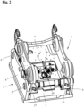
- a quick coupler 1 is shown for easily and conveniently changing different attachments on construction machines, in particular excavators.
- swivel buckets, grippers, scissors, magnets, compressors, hydraulic hammers or other mechanical or hydraulic attachments can be attached, for example via an in Figure 2
- Adapter 2 shown can be easily and conveniently coupled or uncoupled from a driver's cab to a boom or other attachment of an excavator or other construction vehicle.
- the adapter 2 which can be attached to an attachment, contains a base plate 3 and two mutually parallel side cheeks 4, between which a first bolt-shaped coupling element 5 and a second bolt-shaped coupling element 6 spaced therefrom at a predetermined distance for releasably connecting to the quick coupler 1 are arranged.
- the two bolt-shaped coupling elements 5 and 6 can be inserted into corresponding holes in the side walls 4 and fixed there.
- the bolt-shaped coupling elements 5 and 6 can also be arranged directly on the attachment.
- Quick coupler 1 shown in different perspectives contains a carrier 7 designed as a welded or cast part, which has first receptacles 8, which are open towards the front on one side, for receiving and holding the first bolt-shaped coupling element 5 and, on the other side, second receptacles 9 which are open downwards and have a locking element 10 for receiving and holding the second bolt-shaped coupling element 6.
- the quick coupler 1 contains two spaced-apart receptacles 8 for the first coupling element 5 on one side of the carrier 7 and two receptacles 9 for the second coupling element 6 on the other side.
- the first receptacles 8, which are open towards the front, are claw-shaped or designed fork-shaped.
- the second receptacles 9, which are open at the bottom, have a curved contact surface 11 for the contact of the second bolt-shaped coupling element 6.
- the carrier 9 contains on its top side two mutually parallel side parts 12, in which continuous openings 13 are provided for fastening bolts, not shown, for fastening the quick coupler 1 to a boom of an excavator or a connecting part of another construction vehicle.
- the quick coupler 1 also contains two locking elements 10 designed as locking bolts, which are located within the carrier 7 in Figure 1a shown guide holes 14 slidably guided and together by an in Figure 1b H-shaped cylinder 15 shown can be moved hydraulically between a retracted release position for releasing or coupling an attachment and an extended locking position V.
- the downwardly open second receptacles 9 are closed on the underside by the locking elements 10 arranged in the guide bores 14, so that the second bolt-shaped coupling element 6 is gripped under by the locking elements 10.
- Catch hooks 17 that can be pivoted about a transverse axis 16 are also arranged on the receptacles 8 for the first coupling element 5. These catch hooks 17 are from the Coupling elements 5 can be pivoted via a nose 18 between a downwardly pivoted coupling position and an upwardly pivoted closed position.
- the quick coupler 1 which is usually arranged on a boom of an excavator, is used in accordance with Figure 3A first moved in such a way that the first coupling element 5, which is arranged, for example, on the adapter 2 or on the attachment, is moved into the claw-shaped or fork-shaped receptacles 8 on one side of the quick coupler 1.
- the catch hooks 17 are also moved via the lugs 18 from the downwardly pivoted coupling position into the upwardly pivoted closed position.
- the locking elements 10 are in a release position L that is completely retracted into the carrier 7.
- the quick coupler 1 is pivoted around the first bolt-shaped coupling element 5 with the locking elements 10 still retracted so that the second coupling element 6 is attached to the adapter 2 or attachment according to Figure 3b comes to rest on the contact surfaces 11 of the downwardly open receptacles 9 on the other side of the quick coupler 1.
- the locking elements 10, which are displaceably arranged in the guide bores 14 in the carrier 7 of the quick coupler 1 can then be moved hydraulically into an in Figure 3b shown locking position V are extended, so that the second bolt-shaped coupling element 6 is gripped under by the two locking elements 10 on the quick coupler 1 and the attachment is thus held on the quick coupler 1.
- a faulty coupling process occurs, for example, if the locking elements 11 are extended before the coupling elements 5 are in their correct locking position, ie they hit the lower contact surface 11 of the carrier 7. This can be the case, for example, if the quick coupler 1 is not lowered properly due to incorrect operation or due to contamination between adapter 2 and quick coupler 1.
- the locking elements 10 extend, but without capturing the coupling elements 5 of the adapter 2 and bracing them relative to the carrier 7 of the quick coupler 1.
- the Locking elements 10 move as in Fig. 3c shown above the bolt-shaped coupling elements 5, so that there is no firm connection between adapter 2 and quick coupler 1.
- the display device 19 has an electrical control device 21 for checking a correct locking state or a correct position of the locking element 10, which is movable between a retracted release position, an extended locking position V and an unlocked extended position U that deviates from the locking position, and one connected to the control device 21 Electrical locking display 20 for displaying at least one correct locking position V with a first signal and for displaying an unlocked extended position U and / or retracted release position of the locking element 10 that deviates from the correct locking position V by a second signal.
- the second signal merely consists of deactivating the first signal.
- the electrical control device 21 is designed as a switch actuated by the movement of the locking element 10 with a first switching element 22 assigned to the locking element 10 and a second switching element 23 assigned to the locking indicator 20 for controlling the signal generator 21.
- the second switching element 23 is designed as a button that is actuated by the first switching element 22 and can be moved in one axis.
- the button is designed as a roller button.
- the first switching element 22 is designed as a cam slide (linear cam) with a cam 24 that interacts with the second switching element 23.
- the electrical control device 21 can also be designed as a non-contact switch, such as an inductive proximity sensor or the like.
- the cam slide has a control cam with exactly one cam 24, the cam or the position of the cam encoding a correct locking position V of the locking element 10.
- the cam here is designed as a sinusoidal elevation with a certain height.
- the first switching element 22, designed here as a cam slide with the cam 24, has an in Figure 2 shown, rigid linkage 25 and a holder 26 connected to the cylinder 15 used to move the locking elements 10. By displacing the locking elements 10 via the cylinder 15 into the Figures 3a to 3c In the positions shown, the first switching element 22, designed as a cam slide with the cam 24, is also moved into the position via the linkage 25 Figures 4a to 4c positions shown moved.
- the electrical control device 21 is designed in such a way that the electrical locking indicator 20 comprising signal generators is only activated when the locking elements 10 are in the in Figure 3b locking position V shown.
- the signal generators of the electrical locking indicator 20, which are controlled by the electrical control device 21, are designed as optical signal generators 27 with two lamps designed here as light-emitting diodes. Using two separate light sources, the visibility of the light display can be improved.
- the electrical locking indicator can also have acoustic signaling devices, for example a loudspeaker.
- the locking indicator 20 is activated in the form of the lamps, ie the control device 21 here closes a circuit in the form of the second switching element 22 for operating the lamps.
- the second switching element acts here as an analog switch or is connected to one, so that the second switching element 23 deflected by the cam 24 directly controls the electrical locking indicator.
- an electrical processing device could also be connected upstream or downstream of the second switching element 23 for indirectly closing the circuit.
- the circuit can be a circuit belonging to the on-board electrical system of the construction machine.
- the electrical display device 19 it is also conceivable and possible for the electrical display device 19 to be supplied independently, for example by a rechargeable battery element. This could be mounted inside the housing 28, for example.
- the cam slider has a plurality of cams 24 with different heights, which encode different positions or states of the locking elements 10.
- the electrical locking indicator 20 and the electrical control device 21 are housed in a common housing 28.
- the housing which is designed here in a square shape, is transparent on its top with a transparent cover plate.
- the housing could have transparent elements on other sides or could also be made completely transparent.
- Other housing shapes not shown in the exemplary embodiment are possible, in particular round, semicircular or dome-shaped housing shapes. The shape can advantageously improve visibility on several sides.
- the housing can also be partially or completely semi-transparent. This reduces glare and increases the illuminated area.
- a connection 29 for connection to external displays or the like is attached to the housing 28. Signals from the display device can be picked up via the connection and, for example, forwarded for output on an external screen located in the driver's cab of a construction machine.
Landscapes
- Engineering & Computer Science (AREA)
- Mechanical Engineering (AREA)
- General Engineering & Computer Science (AREA)
- Mining & Mineral Resources (AREA)
- Civil Engineering (AREA)
- Structural Engineering (AREA)
- Physics & Mathematics (AREA)
- General Physics & Mathematics (AREA)
- Electromagnetism (AREA)
- Acoustics & Sound (AREA)
- Component Parts Of Construction Machinery (AREA)
- Quick-Acting Or Multi-Walled Pipe Joints (AREA)
- Shovels (AREA)
- Human Computer Interaction (AREA)
Claims (11)
- Attache rapide (1) pour le changement automatique d'un accessoire sur un engin de chantier, qui comporte des premiers logements (8) disposés sur une face d'un support (7) pour la réception d'un premier élément d'accouplement (5), des deuxièmes logements (9) disposés sur l'autre face du support (7) avec au moins un élément de verrouillage (10) mobile entre une position de libération pour l'accouplement ou le désaccouplement de l'accessoire et une position de verrouillage (V) pour la retenue de l'accessoire (2) sur l'attache rapide (1) pour la réception d'un deuxième élément d'accouplement (6) et un dispositif d'affichage (19) disposé sur le support (7) pour le contrôle du verrouillage, caractérisée en ce que le dispositif d'affichage (19) disposé sur le support (7) comporte un écran de verrouillage (20) électrique et un système de commande électrique (21), lequel active l'écran de verrouillage (20) dans une position de verrouillage (V) sortie de l'élément de verrouillage (10) et le désactive dans une position de libération rentrée et une position sortie (U) de l'élément de verrouillage (10) différente de la position de verrouillage.
- Attache rapide (1) selon la revendication 1 caractérisée en ce que le système de commande électrique (21) est réalisé sous la forme d'un commutateur commandé par le mouvement de l'élément de verrouillage (10) avec un premier élément de commutation (22) associé à l'élément de verrouillage (10) et un deuxième élément de commutation (23) associé à l'écran de verrouillage (20) pour la commande de l'écran de verrouillage (21) .
- Attache rapide (1) selon la revendication 2, caractérisée en ce que le deuxième élément de commutation (23) est réalisé sous la forme d'un bouton-poussoir actionné par le premier élément de commutation (22).
- Attache rapide (1) selon la revendication 2 ou 3, caractérisée en ce que le premier élément de commutation (22) comporte au moins une came (24) coopérant avec le deuxième élément de commutation (23).
- Attache rapide (1) selon la revendication 2 ou 3, caractérisée en ce que le deuxième élément de commutation (23) est relié mécaniquement à l'élément de verrouillage (10) par l'intermédiaire d'une tringlerie (25), en particulier d'une tringlerie fixe.
- Attache rapide (1) selon l'une quelconque des revendications 2 à 5, caractérisée en ce que l'écran de verrouillage (20) électrique comprend au moins un générateur de signaux optiques et/ou acoustiques (27).
- Attache rapide (1) selon la revendication 6, caractérisée en ce que le générateur de signaux optiques (27) de l'écran de verrouillage (20) électrique est réalisé sous la forme d'un moyen d'éclairage.
- Attache rapide (1) selon l'une quelconque des revendications précédentes, caractérisée en ce que l'écran de verrouillage (20) électrique et le système de commande électrique (21) sont logés dans un boîtier (28) commun.
- Attache rapide (1) selon la revendication 8, caractérisée en ce que le boîtier (28) est conçu de manière transparente ou semi-transparente.
- Attache rapide (1) selon l'une quelconque des revendications précédentes, caractérisée en ce que le dispositif d'affichage (19) présente un raccord (29) pour le raccordement d'un écran externe.
- Utilisation d'un dispositif d'affichage (19) pour une attache rapide (1) pour le changement automatique d'un accessoire sur un engin de chantier, qui présente des premiers logements (8) disposés sur une face d'un support (7) pour la réception d'un premier élément d'accouplement (5), des deuxièmes logements (9) disposés sur l'autre face du support (7) avec au moins un élément de verrouillage (10) mobile entre une position de libération pour l'accouplement ou le désaccouplement de l'accessoire et une position de verrouillage (V) pour la retenue de l'accessoire (2) sur l'attache rapide (1) pour la réception d'un deuxième élément d'accouplement (6) et un dispositif d'affichage (19) disposé sur le support (10) pour le contrôle du verrouillage, caractérisée en ce que le dispositif d'affichage (19) disposé sur le support (7) comporte un écran de verrouillage (20) électrique et un système de commande électrique (21), lequel active l'écran de verrouillage (20) dans une position de verrouillage (V) sortie de l'élément de verrouillage (10) et le désactive dans une position de libération rentrée et une position sortie (U) de l'élément de verrouillage (10) différente de la position de verrouillage.
Applications Claiming Priority (1)
| Application Number | Priority Date | Filing Date | Title |
|---|---|---|---|
| DE102019118913.6A DE102019118913A1 (de) | 2019-07-12 | 2019-07-12 | Schnellwechsler |
Publications (2)
| Publication Number | Publication Date |
|---|---|
| EP3763882A1 EP3763882A1 (fr) | 2021-01-13 |
| EP3763882B1 true EP3763882B1 (fr) | 2023-11-15 |
Family
ID=70857063
Family Applications (1)
| Application Number | Title | Priority Date | Filing Date |
|---|---|---|---|
| EP20176499.0A Active EP3763882B1 (fr) | 2019-07-12 | 2020-05-26 | Dispositif de changement rapide |
Country Status (11)
| Country | Link |
|---|---|
| US (1) | US11482083B2 (fr) |
| EP (1) | EP3763882B1 (fr) |
| JP (1) | JP7029193B2 (fr) |
| AU (1) | AU2020203764B2 (fr) |
| CA (1) | CA3082989A1 (fr) |
| DE (1) | DE102019118913A1 (fr) |
| DK (1) | DK3763882T3 (fr) |
| ES (1) | ES2969228T3 (fr) |
| FI (1) | FI3763882T3 (fr) |
| HU (1) | HUE064481T2 (fr) |
| PL (1) | PL3763882T3 (fr) |
Families Citing this family (7)
| Publication number | Priority date | Publication date | Assignee | Title |
|---|---|---|---|---|
| US11536009B2 (en) | 2019-07-26 | 2022-12-27 | Deere & Company | System for detecting locking pin engagement of an implement |
| USD931909S1 (en) * | 2020-02-04 | 2021-09-28 | Deere & Company | Implement connection system |
| DE102020115197A1 (de) * | 2020-06-08 | 2021-12-09 | OilQuick Deutschland KG | Adapter für ein Schnellwechselsystem und Schnellwechselsystem mit einem derartigen Adapter |
| SE546540C2 (en) * | 2021-07-09 | 2024-11-26 | Smp Parts Ab | Quick coupling device comprising position sensors and a control unit arranged to control locking and maintenance of the device |
| CN114319477B (zh) * | 2022-03-14 | 2022-05-17 | 徐州巴特工程机械股份有限公司 | 一种挖掘机用液压式快换连接器 |
| EP4375426A1 (fr) * | 2022-11-28 | 2024-05-29 | Oilquick AB | Porte-outil pour une machine avec un système de positionnement |
| KR102707339B1 (ko) * | 2023-11-24 | 2024-09-19 | (주) 기린 | 커플러와 어댑터의 자동 착탈 및 원터치 유로 연결을 위한 더블실린더 |
Family Cites Families (15)
| Publication number | Priority date | Publication date | Assignee | Title |
|---|---|---|---|---|
| SE524941C2 (sv) * | 2003-02-17 | 2004-10-26 | Oilquick Ab | System innefattande redskapsfäste och arbetsredskap |
| AT9066U1 (de) * | 2005-12-23 | 2007-04-15 | Perwein Baumaschinen Systeme G | Kupplungsvorrichtung zum befestigen eines arbeitswerkzeugs an einem ausleger |
| GB2451304B (en) * | 2007-12-31 | 2009-11-18 | Quick Switch | Quick Hitch |
| GB2464988B8 (en) * | 2008-11-03 | 2013-02-20 | Miller Int Ltd | Coupler with coupling status sensors |
| JP5240172B2 (ja) * | 2009-11-24 | 2013-07-17 | トヨタ自動車株式会社 | 車両用シフト制御装置 |
| DE102010016492A1 (de) * | 2010-04-16 | 2011-10-20 | Lehnhoff Hartstahl Gmbh & Co. Kg | Werkzeugzustandsüberwachung |
| GB2486887A (en) * | 2010-12-21 | 2012-07-04 | Miller Int Ltd | Quick coupler status alarm |
| DE102011000057A1 (de) * | 2011-01-07 | 2012-07-12 | Claas Selbstfahrende Erntemaschinen Gmbh | Mähdrescher mit einer Verteilvorrichtung zur Verteilung gehäckselten Erntegutes |
| WO2014058380A1 (fr) * | 2012-10-08 | 2014-04-17 | Indexator Group Ab | Appareil de raccordement de dispositif/d'outil et procédé associé |
| WO2014168540A1 (fr) * | 2013-04-09 | 2014-10-16 | Indexator Group Ab | Système pour commander un raccord rapide agencé sur un bras d'outil |
| US9574319B2 (en) | 2014-08-11 | 2017-02-21 | Caterpillar Inc. | Positive indicator for couplers |
| GB2535194B (en) * | 2015-02-12 | 2018-07-11 | Caterpillar Inc | Engagement indicator system |
| US10590631B2 (en) * | 2015-03-25 | 2020-03-17 | Wedgelock Equipment Limited | Visual indicator for a coupler |
| CN107272528A (zh) * | 2016-04-07 | 2017-10-20 | 卡特彼勒公司 | 用于工装快换装置的控制方法和控制设备 |
| GB201703831D0 (en) * | 2017-03-10 | 2017-04-26 | Agco Do Brazil Comercio E Ind Ltda | Lock proving system for an agricultural machine attachment |
-
2019
- 2019-07-12 DE DE102019118913.6A patent/DE102019118913A1/de not_active Withdrawn
-
2020
- 2020-05-26 PL PL20176499.0T patent/PL3763882T3/pl unknown
- 2020-05-26 HU HUE20176499A patent/HUE064481T2/hu unknown
- 2020-05-26 ES ES20176499T patent/ES2969228T3/es active Active
- 2020-05-26 DK DK20176499.0T patent/DK3763882T3/da active
- 2020-05-26 EP EP20176499.0A patent/EP3763882B1/fr active Active
- 2020-05-26 FI FIEP20176499.0T patent/FI3763882T3/en active
- 2020-06-05 CA CA3082989A patent/CA3082989A1/fr active Pending
- 2020-06-08 AU AU2020203764A patent/AU2020203764B2/en active Active
- 2020-07-06 JP JP2020116131A patent/JP7029193B2/ja active Active
- 2020-07-10 US US16/925,553 patent/US11482083B2/en active Active
Also Published As
| Publication number | Publication date |
|---|---|
| AU2020203764B2 (en) | 2024-08-15 |
| JP2021014780A (ja) | 2021-02-12 |
| US20210010242A1 (en) | 2021-01-14 |
| FI3763882T3 (en) | 2024-01-02 |
| DE102019118913A1 (de) | 2021-01-14 |
| DK3763882T3 (da) | 2023-12-18 |
| ES2969228T3 (es) | 2024-05-17 |
| AU2020203764A1 (en) | 2021-01-28 |
| HUE064481T2 (hu) | 2024-03-28 |
| EP3763882A1 (fr) | 2021-01-13 |
| US11482083B2 (en) | 2022-10-25 |
| JP7029193B2 (ja) | 2022-03-03 |
| PL3763882T3 (pl) | 2024-04-08 |
| CA3082989A1 (fr) | 2021-01-12 |
Similar Documents
| Publication | Publication Date | Title |
|---|---|---|
| EP3763882B1 (fr) | Dispositif de changement rapide | |
| EP3591122B1 (fr) | Système de changement rapide | |
| EP0391225B1 (fr) | Circuit de sécurité avec contacteurs pour dispositifs de renversement et/ou de levage | |
| EP0464410B1 (fr) | Combination de logement d'ustensiles et unité d'alimentation de déplacement vertical | |
| DE3249143T1 (de) | Fernbetaetigbarer schnappmechanismus und verriegelungsbolzen fuer einen ausleger aus mehreren abschnitten und mit einem handbetaetigten endabschnitt | |
| EP3024099A1 (fr) | Dispositif de traitement de câble | |
| DE19524226C2 (de) | Metallabfall-Beseitungsvorrichtung | |
| EP3730697B1 (fr) | Adaptateur pour un système de changement rapide et système de changement rapide doté d'un tel adaptateur | |
| DE102005005991A1 (de) | Konsole für eine drehbare Sitz- und Bedieneinheit eines Nutzfahrzeugs | |
| DE112014000182T5 (de) | Arbeitsfahrzeug und Rundumkennleuchte | |
| EP3107211B1 (fr) | Unité de commande pour une plate-forme élévatrice, machine de travail mobile ou engin | |
| DE10256385B3 (de) | Spannvorrichtung, insbesondere Kniehebelspannvorrichtung | |
| EP0617298B1 (fr) | Dispositif de réception d'instruments médicaux ou dentaires avec une barrière optique | |
| DE102015114632A1 (de) | Signalleuchte für Fahrzeuge | |
| DE202019105122U1 (de) | Bindemaschine | |
| DE9112245U1 (de) | Vorrichtung zur Anpassung eines Antriebselementes an ein Zuggeschirr für Straßenfahrzeuge | |
| DE19922500A1 (de) | Modulare Schaltervorrichtung, insbesondere für Kraftahrzeuge | |
| EP1171897B1 (fr) | Dispositif de commande d'une liaison en fonction de l'etat d'un dispositif a surveiller, en particulier commutateur de securite | |
| DE102013001546B4 (de) | Vorrichtung zum lösbaren Arretieren eines vorgebbaren Zustandes einer Einrichtung sowie Sicherheitsschalter mit einer solchen Vorrichtung | |
| EP3986746B1 (fr) | Dispositif indicateur et siège de véhicule | |
| EP0038452A2 (fr) | Dispositif de commande pour appareil dentaire | |
| DE975910C (de) | Kommandogeraet fuer Arbeitsmaschinen mit bewegbaren Organen, insbesondere fuer Werkzeugmaschinen, Hebezeuge und Verladevorrichtungen | |
| DE474122C (de) | Vorrichtung zur Sicherung der Arbeiter beim maschinellen Gleisstopfbetriebe | |
| EP0385049B1 (fr) | Garde-porte | |
| EP3018271B1 (fr) | Barre anti-panique |
Legal Events
| Date | Code | Title | Description |
|---|---|---|---|
| PUAI | Public reference made under article 153(3) epc to a published international application that has entered the european phase |
Free format text: ORIGINAL CODE: 0009012 |
|
| STAA | Information on the status of an ep patent application or granted ep patent |
Free format text: STATUS: THE APPLICATION HAS BEEN PUBLISHED |
|
| AK | Designated contracting states |
Kind code of ref document: A1 Designated state(s): AL AT BE BG CH CY CZ DE DK EE ES FI FR GB GR HR HU IE IS IT LI LT LU LV MC MK MT NL NO PL PT RO RS SE SI SK SM TR |
|
| AX | Request for extension of the european patent |
Extension state: BA ME |
|
| STAA | Information on the status of an ep patent application or granted ep patent |
Free format text: STATUS: REQUEST FOR EXAMINATION WAS MADE |
|
| 17P | Request for examination filed |
Effective date: 20210713 |
|
| RBV | Designated contracting states (corrected) |
Designated state(s): AL AT BE BG CH CY CZ DE DK EE ES FI FR GB GR HR HU IE IS IT LI LT LU LV MC MK MT NL NO PL PT RO RS SE SI SK SM TR |
|
| GRAP | Despatch of communication of intention to grant a patent |
Free format text: ORIGINAL CODE: EPIDOSNIGR1 |
|
| STAA | Information on the status of an ep patent application or granted ep patent |
Free format text: STATUS: GRANT OF PATENT IS INTENDED |
|
| INTG | Intention to grant announced |
Effective date: 20230710 |
|
| GRAS | Grant fee paid |
Free format text: ORIGINAL CODE: EPIDOSNIGR3 |
|
| GRAA | (expected) grant |
Free format text: ORIGINAL CODE: 0009210 |
|
| STAA | Information on the status of an ep patent application or granted ep patent |
Free format text: STATUS: THE PATENT HAS BEEN GRANTED |
|
| AK | Designated contracting states |
Kind code of ref document: B1 Designated state(s): AL AT BE BG CH CY CZ DE DK EE ES FI FR GB GR HR HU IE IS IT LI LT LU LV MC MK MT NL NO PL PT RO RS SE SI SK SM TR |
|
| REG | Reference to a national code |
Ref country code: CH Ref legal event code: EP Ref country code: GB Ref legal event code: FG4D Free format text: NOT ENGLISH |
|
| P01 | Opt-out of the competence of the unified patent court (upc) registered |
Effective date: 20231020 |
|
| REG | Reference to a national code |
Ref country code: DE Ref legal event code: R096 Ref document number: 502020006003 Country of ref document: DE |
|
| REG | Reference to a national code |
Ref country code: IE Ref legal event code: FG4D Free format text: LANGUAGE OF EP DOCUMENT: GERMAN |
|
| REG | Reference to a national code |
Ref country code: DK Ref legal event code: T3 Effective date: 20231212 |
|
| REG | Reference to a national code |
Ref country code: FI Ref legal event code: FGE Ref country code: SE Ref legal event code: TRGR |
|
| REG | Reference to a national code |
Ref country code: NL Ref legal event code: FP |
|
| REG | Reference to a national code |
Ref country code: NO Ref legal event code: T2 Effective date: 20231115 |
|
| REG | Reference to a national code |
Ref country code: SK Ref legal event code: T3 Ref document number: E 43113 Country of ref document: SK |
|
| REG | Reference to a national code |
Ref country code: LT Ref legal event code: MG9D |
|
| REG | Reference to a national code |
Ref country code: HU Ref legal event code: AG4A Ref document number: E064481 Country of ref document: HU |
|
| PG25 | Lapsed in a contracting state [announced via postgrant information from national office to epo] |
Ref country code: GR Free format text: LAPSE BECAUSE OF FAILURE TO SUBMIT A TRANSLATION OF THE DESCRIPTION OR TO PAY THE FEE WITHIN THE PRESCRIBED TIME-LIMIT Effective date: 20240216 |
|
| PG25 | Lapsed in a contracting state [announced via postgrant information from national office to epo] |
Ref country code: IS Free format text: LAPSE BECAUSE OF FAILURE TO SUBMIT A TRANSLATION OF THE DESCRIPTION OR TO PAY THE FEE WITHIN THE PRESCRIBED TIME-LIMIT Effective date: 20240315 |
|
| PG25 | Lapsed in a contracting state [announced via postgrant information from national office to epo] |
Ref country code: LT Free format text: LAPSE BECAUSE OF FAILURE TO SUBMIT A TRANSLATION OF THE DESCRIPTION OR TO PAY THE FEE WITHIN THE PRESCRIBED TIME-LIMIT Effective date: 20231115 |
|
| PG25 | Lapsed in a contracting state [announced via postgrant information from national office to epo] |
Ref country code: LT Free format text: LAPSE BECAUSE OF FAILURE TO SUBMIT A TRANSLATION OF THE DESCRIPTION OR TO PAY THE FEE WITHIN THE PRESCRIBED TIME-LIMIT Effective date: 20231115 Ref country code: IS Free format text: LAPSE BECAUSE OF FAILURE TO SUBMIT A TRANSLATION OF THE DESCRIPTION OR TO PAY THE FEE WITHIN THE PRESCRIBED TIME-LIMIT Effective date: 20240315 Ref country code: GR Free format text: LAPSE BECAUSE OF FAILURE TO SUBMIT A TRANSLATION OF THE DESCRIPTION OR TO PAY THE FEE WITHIN THE PRESCRIBED TIME-LIMIT Effective date: 20240216 Ref country code: BG Free format text: LAPSE BECAUSE OF FAILURE TO SUBMIT A TRANSLATION OF THE DESCRIPTION OR TO PAY THE FEE WITHIN THE PRESCRIBED TIME-LIMIT Effective date: 20240215 Ref country code: PT Free format text: LAPSE BECAUSE OF FAILURE TO SUBMIT A TRANSLATION OF THE DESCRIPTION OR TO PAY THE FEE WITHIN THE PRESCRIBED TIME-LIMIT Effective date: 20240315 |
|
| REG | Reference to a national code |
Ref country code: ES Ref legal event code: FG2A Ref document number: 2969228 Country of ref document: ES Kind code of ref document: T3 Effective date: 20240517 |
|
| PG25 | Lapsed in a contracting state [announced via postgrant information from national office to epo] |
Ref country code: RS Free format text: LAPSE BECAUSE OF FAILURE TO SUBMIT A TRANSLATION OF THE DESCRIPTION OR TO PAY THE FEE WITHIN THE PRESCRIBED TIME-LIMIT Effective date: 20231115 Ref country code: LV Free format text: LAPSE BECAUSE OF FAILURE TO SUBMIT A TRANSLATION OF THE DESCRIPTION OR TO PAY THE FEE WITHIN THE PRESCRIBED TIME-LIMIT Effective date: 20231115 Ref country code: HR Free format text: LAPSE BECAUSE OF FAILURE TO SUBMIT A TRANSLATION OF THE DESCRIPTION OR TO PAY THE FEE WITHIN THE PRESCRIBED TIME-LIMIT Effective date: 20231115 |
|
| PG25 | Lapsed in a contracting state [announced via postgrant information from national office to epo] |
Ref country code: SM Free format text: LAPSE BECAUSE OF FAILURE TO SUBMIT A TRANSLATION OF THE DESCRIPTION OR TO PAY THE FEE WITHIN THE PRESCRIBED TIME-LIMIT Effective date: 20231115 Ref country code: RO Free format text: LAPSE BECAUSE OF FAILURE TO SUBMIT A TRANSLATION OF THE DESCRIPTION OR TO PAY THE FEE WITHIN THE PRESCRIBED TIME-LIMIT Effective date: 20231115 Ref country code: EE Free format text: LAPSE BECAUSE OF FAILURE TO SUBMIT A TRANSLATION OF THE DESCRIPTION OR TO PAY THE FEE WITHIN THE PRESCRIBED TIME-LIMIT Effective date: 20231115 |
|
| REG | Reference to a national code |
Ref country code: DE Ref legal event code: R097 Ref document number: 502020006003 Country of ref document: DE |
|
| PLBE | No opposition filed within time limit |
Free format text: ORIGINAL CODE: 0009261 |
|
| STAA | Information on the status of an ep patent application or granted ep patent |
Free format text: STATUS: NO OPPOSITION FILED WITHIN TIME LIMIT |
|
| 26N | No opposition filed |
Effective date: 20240819 |
|
| PG25 | Lapsed in a contracting state [announced via postgrant information from national office to epo] |
Ref country code: SI Free format text: LAPSE BECAUSE OF FAILURE TO SUBMIT A TRANSLATION OF THE DESCRIPTION OR TO PAY THE FEE WITHIN THE PRESCRIBED TIME-LIMIT Effective date: 20231115 |
|
| PG25 | Lapsed in a contracting state [announced via postgrant information from national office to epo] |
Ref country code: SI Free format text: LAPSE BECAUSE OF FAILURE TO SUBMIT A TRANSLATION OF THE DESCRIPTION OR TO PAY THE FEE WITHIN THE PRESCRIBED TIME-LIMIT Effective date: 20231115 |
|
| PG25 | Lapsed in a contracting state [announced via postgrant information from national office to epo] |
Ref country code: MC Free format text: LAPSE BECAUSE OF FAILURE TO SUBMIT A TRANSLATION OF THE DESCRIPTION OR TO PAY THE FEE WITHIN THE PRESCRIBED TIME-LIMIT Effective date: 20231115 |
|
| PG25 | Lapsed in a contracting state [announced via postgrant information from national office to epo] |
Ref country code: MC Free format text: LAPSE BECAUSE OF FAILURE TO SUBMIT A TRANSLATION OF THE DESCRIPTION OR TO PAY THE FEE WITHIN THE PRESCRIBED TIME-LIMIT Effective date: 20231115 |
|
| PGFP | Annual fee paid to national office [announced via postgrant information from national office to epo] |
Ref country code: SE Payment date: 20250311 Year of fee payment: 6 |
|
| PG25 | Lapsed in a contracting state [announced via postgrant information from national office to epo] |
Ref country code: IE Free format text: LAPSE BECAUSE OF NON-PAYMENT OF DUE FEES Effective date: 20240526 |
|
| PGFP | Annual fee paid to national office [announced via postgrant information from national office to epo] |
Ref country code: NL Payment date: 20250522 Year of fee payment: 6 |
|
| PGFP | Annual fee paid to national office [announced via postgrant information from national office to epo] |
Ref country code: FI Payment date: 20250520 Year of fee payment: 6 |
|
| PGFP | Annual fee paid to national office [announced via postgrant information from national office to epo] |
Ref country code: PL Payment date: 20250515 Year of fee payment: 6 Ref country code: DE Payment date: 20250606 Year of fee payment: 6 |
|
| PGFP | Annual fee paid to national office [announced via postgrant information from national office to epo] |
Ref country code: ES Payment date: 20250616 Year of fee payment: 6 Ref country code: DK Payment date: 20250521 Year of fee payment: 6 |
|
| PGFP | Annual fee paid to national office [announced via postgrant information from national office to epo] |
Ref country code: HU Payment date: 20250519 Year of fee payment: 6 Ref country code: NO Payment date: 20250520 Year of fee payment: 6 |
|
| PGFP | Annual fee paid to national office [announced via postgrant information from national office to epo] |
Ref country code: LU Payment date: 20250520 Year of fee payment: 6 Ref country code: BE Payment date: 20250520 Year of fee payment: 6 Ref country code: IT Payment date: 20250530 Year of fee payment: 6 |
|
| PGFP | Annual fee paid to national office [announced via postgrant information from national office to epo] |
Ref country code: FR Payment date: 20250521 Year of fee payment: 6 |
|
| PGFP | Annual fee paid to national office [announced via postgrant information from national office to epo] |
Ref country code: CH Payment date: 20250601 Year of fee payment: 6 |
|
| PGFP | Annual fee paid to national office [announced via postgrant information from national office to epo] |
Ref country code: AT Payment date: 20250519 Year of fee payment: 6 |
|
| PGFP | Annual fee paid to national office [announced via postgrant information from national office to epo] |
Ref country code: SK Payment date: 20250520 Year of fee payment: 6 Ref country code: TR Payment date: 20250516 Year of fee payment: 6 |
|
| PGFP | Annual fee paid to national office [announced via postgrant information from national office to epo] |
Ref country code: CZ Payment date: 20250514 Year of fee payment: 6 |
|
| PG25 | Lapsed in a contracting state [announced via postgrant information from national office to epo] |
Ref country code: CY Free format text: LAPSE BECAUSE OF FAILURE TO SUBMIT A TRANSLATION OF THE DESCRIPTION OR TO PAY THE FEE WITHIN THE PRESCRIBED TIME-LIMIT; INVALID AB INITIO Effective date: 20200526 |
|
| PGFP | Annual fee paid to national office [announced via postgrant information from national office to epo] |
Ref country code: GB Payment date: 20260324 Year of fee payment: 7 |