EP3764013A1 - Vorrichtung zum aufhängen von rechteckigen kanalelementen und kanalsystem - Google Patents
Vorrichtung zum aufhängen von rechteckigen kanalelementen und kanalsystem Download PDFInfo
- Publication number
- EP3764013A1 EP3764013A1 EP20171540.6A EP20171540A EP3764013A1 EP 3764013 A1 EP3764013 A1 EP 3764013A1 EP 20171540 A EP20171540 A EP 20171540A EP 3764013 A1 EP3764013 A1 EP 3764013A1
- Authority
- EP
- European Patent Office
- Prior art keywords
- elements
- support rail
- web
- channel elements
- longitudinal groove
- Prior art date
- Legal status (The legal status is an assumption and is not a legal conclusion. Google has not performed a legal analysis and makes no representation as to the accuracy of the status listed.)
- Granted
Links
Images



Classifications
-
- F—MECHANICAL ENGINEERING; LIGHTING; HEATING; WEAPONS; BLASTING
- F24—HEATING; RANGES; VENTILATING
- F24F—AIR-CONDITIONING; AIR-HUMIDIFICATION; VENTILATION; USE OF AIR CURRENTS FOR SCREENING
- F24F13/00—Details common to, or for air-conditioning, air-humidification, ventilation or use of air currents for screening
- F24F13/02—Ducting arrangements
- F24F13/0254—Ducting arrangements characterised by their mounting means, e.g. supports
-
- F—MECHANICAL ENGINEERING; LIGHTING; HEATING; WEAPONS; BLASTING
- F16—ENGINEERING ELEMENTS AND UNITS; GENERAL MEASURES FOR PRODUCING AND MAINTAINING EFFECTIVE FUNCTIONING OF MACHINES OR INSTALLATIONS; THERMAL INSULATION IN GENERAL
- F16L—PIPES; JOINTS OR FITTINGS FOR PIPES; SUPPORTS FOR PIPES, CABLES OR PROTECTIVE TUBING; MEANS FOR THERMAL INSULATION IN GENERAL
- F16L3/00—Supports for pipes, cables or protective tubing, e.g. hangers, holders, clamps, cleats, clips, brackets
- F16L3/006—Supports for pipes, cables or protective tubing, e.g. hangers, holders, clamps, cleats, clips, brackets for pipes with a rectangular cross-section
-
- F—MECHANICAL ENGINEERING; LIGHTING; HEATING; WEAPONS; BLASTING
- F16—ENGINEERING ELEMENTS AND UNITS; GENERAL MEASURES FOR PRODUCING AND MAINTAINING EFFECTIVE FUNCTIONING OF MACHINES OR INSTALLATIONS; THERMAL INSULATION IN GENERAL
- F16L—PIPES; JOINTS OR FITTINGS FOR PIPES; SUPPORTS FOR PIPES, CABLES OR PROTECTIVE TUBING; MEANS FOR THERMAL INSULATION IN GENERAL
- F16L3/00—Supports for pipes, cables or protective tubing, e.g. hangers, holders, clamps, cleats, clips, brackets
- F16L3/24—Supports for pipes, cables or protective tubing, e.g. hangers, holders, clamps, cleats, clips, brackets with special member for attachment to profiled girders
-
- F—MECHANICAL ENGINEERING; LIGHTING; HEATING; WEAPONS; BLASTING
- F24—HEATING; RANGES; VENTILATING
- F24F—AIR-CONDITIONING; AIR-HUMIDIFICATION; VENTILATION; USE OF AIR CURRENTS FOR SCREENING
- F24F13/00—Details common to, or for air-conditioning, air-humidification, ventilation or use of air currents for screening
- F24F13/32—Supports for air-conditioning, air-humidification or ventilation units
Definitions
- the invention relates to a device for hanging rectangular duct elements, in particular ventilation duct elements, with a support rail consisting of a cross-sectional C-shaped profile, in the C-web of which a plurality of openings for inserting a threaded rod or the like are cut out along the longitudinal axis.
- the invention relates to a channel system with rectangular channel elements, in particular ventilation channel elements, which are each provided with circumferential frame profiles on both front sides, which have a bead on the outside, with frame profiles of adjacent channel elements lying against one another on the front side being encompassed on the outside by at least one cross-sectionally C-shaped clamping element, Support rails equipped with threaded rods or the like are provided for hanging up the channel elements.
- Ventilation ducts are usually made from folded metal sheets, which are equipped on their respective end faces with bracing frames formed from metal frame profiles in order to be able to arrange the individual duct elements one after the other and brace them together. Since the clamping force is usually applied via four corner brackets that engage in the frame profiles, there is a risk that the frame profiles forming the end face frames can be pressed apart at a distance from the corners, so that leaks can occur. For this reason, the frame profiles forming the end frame are equipped in the upper area with fixing beads, which are clamped over by devices for bracing in the form of clamping elements or clamps will. These devices are designed, for example, as C-shaped clamps, whereby several such clamps have to be pushed onto adjacent frame profiles of two ventilation duct elements, which is relatively expensive.
- a device with the features of the preamble of claim 1 is known for suspending the ventilation duct elements from a ceiling or the like.
- This device has a mounting rail made of a C-profile, which is arranged on the underside of a ventilation duct element with an upwardly open profile and is suspended by means of threaded rods and fastening screws inserted through openings in the C-web of the mounting rail.
- a sound-absorbing rubber profile is inserted into the mounting rail, which forms the contact surface with the ventilation duct element.
- ring-shaped insulating elements are usually arranged adjacent to the fastening nut. The mounting of the mounting rails is also evident.
- the object of the invention is to improve and simplify the suspension or assembly of duct elements, in particular ventilation duct elements.
- a device is thus made available in which a C-shaped clamping bracket is integrated into the actual mounting rail for the tensioning connection of adjacent frame profiles of two adjacent channel elements, the clamping bracket being formed by the C-shaped longitudinal groove.
- the device is pushed onto the adjacent frame profiles with the longitudinal groove and braces them over their entire length, which at the same time creates a solid, vibration-free connection between the support rail and the duct elements, so that no additional insulating elements are required.
- the additional Effort for mounting a plurality of individual clamping elements or clamping brackets on the channel side facing the support rail it is possible to arrange the support rail on the top of the duct elements or on the underside, ie the duct elements can hang on the support rail or rest on it.
- the longitudinal groove can be designed differently. According to a first embodiment it is provided that the longitudinal groove is designed as an indentation of the C-web. The longitudinal groove is then located inside the support rail.
- the longitudinal groove is designed as a bulge of the C-web.
- the longitudinal groove then protrudes outward from the mounting rail.
- the mounting rail is made of metal.
- the mounting rail is cold rolled.
- the invention also relates to a channel system with rectangular channel elements, in particular ventilation channel elements, which are each provided with circumferential frame profiles on both end faces, which have a bead on the outside, with frame profiles of adjacent channel elements lying against one another on the front side being encompassed on the outside by at least one cross-sectional C-shaped clamping element, Support rails equipped with threaded rods or the like are provided for suspending the duct elements, the duct system being characterized in that a support rail and a clamping element are each formed by a device described above.
- the respective device is arranged on the underside of the channel elements, or that the respective device is arranged on the upper side of the channel elements.
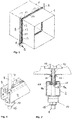
- FIG Figures 1 and 2 and 5 to 10 A device for hanging rectangular ventilation duct elements 1 according to a first embodiment is shown in FIG Figures 1 and 2 and 5 to 10 generally designated 2.
- This device 2 has a support rail 3 made of a cross-sectionally C-shaped profile.
- the two C-legs are denoted by 4 and 5, which are angled inwards at right angles at the free ends 4a and 5a, respectively.
- the support rail 3 is thus open inwards between the outer edges of the two free ends 4a and 5a.
- the C-web connecting the two C-legs 4 and 5 is denoted by 6.
- a plurality of openings 7 are recessed in this C-web over the length of the support rail 3, spaced apart from one another; these openings 7 can be round and / or elongated hole-shaped and serve for inserting a threaded rod 8.
- an outwardly open, cross-sectional C-shaped longitudinal groove 9 is formed with a lateral undercut 9a, 9b on both sides.
- This longitudinal groove 9 is in the device according to Fig. 1 designed as an indentation of the C-web, ie directed into the interior of the support rail 3.
- the C-shaped longitudinal groove 9 in the device 2 ′ is not designed as an indentation but as a bulge of the C-web 6, ie the longitudinal groove 9 protrudes outwardly from the support rail 3.
- each ventilation duct element 1 has a frame profile forming a flange on each side edge 10, these frame profiles 10 being pushed firmly and tightly onto the edge area of the respective side of the ventilation duct element 1 in a manner known per se.
- Two adjacent frame profiles 10 abut one another at the front in the assembled position, each frame profile 10 having an outwardly directed bead 11 on the outside.
- the frame profiles 10 are connected to one another in the area of the corners via indicated corner angles 12.
- C-shaped clamping elements 13 are attached to the frame profiles, which clamp over the two beads 11 of the adjacent frame profiles 10.
- a device 2 is arranged on the underside of the ventilation duct elements 1, in such a way that the support rail 3 with the C-shaped longitudinal groove 9 is pushed up onto the adjacent frame profiles 10 and the beads 11 on the underside.
- the beads 11 rest in a locking manner in the region of the undercuts 9a and 9b of the longitudinal groove 9.
- the device 2 is firmly connected to the underside of the frame profiles 10 and thus to the two ventilation duct elements 1, as best shown Fig. 7 emerges.
- a threaded rod 8 is passed through the support rail 3 through an opening 7 at both ends of the device 2.
- At least one annular insulating element 14 is pushed onto the threaded rod and a fastening nut 15 is screwed on.
- the threaded rod 8 is attached to a ceiling or the like in a manner not shown.
- the device 2 thus serves on the one hand to connect the frame profiles 10 of the ventilation duct elements 1 on the underside and on the other hand to ensure that the two ventilation duct elements rest on the support rail 3 of the device 2.
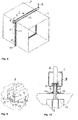
- the device 2 is reversed, i.e. arranged rotated by 180 °, so that the C-shaped longitudinal groove 9 is located on the underside.
- the device 2 is then pushed onto two adjacent frame profiles 10 on the top side in a clamping manner and otherwise fastened in the same way by means of threaded rods 8.
- the ventilation duct elements 1 thus hang on the device 2 via the frame profiles 10.
- Figure 12 shows again a hanging arrangement according to the configuration Figures 8 to 10 . Accordingly, at Fig. 11 the longitudinal groove 9 of the device 2 'is arranged on the top side and the device 2' is pushed with its longitudinal groove 9 onto two frame profiles 10 on the top.
Landscapes
- Engineering & Computer Science (AREA)
- General Engineering & Computer Science (AREA)
- Mechanical Engineering (AREA)
- Chemical & Material Sciences (AREA)
- Combustion & Propulsion (AREA)
- Duct Arrangements (AREA)
- Specific Sealing Or Ventilating Devices For Doors And Windows (AREA)
- Ventilation (AREA)
- Roof Covering Using Slabs Or Stiff Sheets (AREA)
Abstract
Description
- Die Erfindung betrifft eine Vorrichtung zum Aufhängen von rechteckigen Kanalelementen, insbesondere Lüftungskanalelementen, mit einer Tragschiene, welche aus einem querschnittlich C-förmigen Profil besteht, in dessen C-Steg entlang der Längsachse eine Mehrzahl von Öffnungen zum Durchstecken einer Gewindestange oder dgl. ausgespart sind.
- Außerdem betrifft die Erfindung ein Kanalsystem mit rechteckigen Kanalelementen, insbesondere Lüftungskanalelementen, welche an beiden Stirnseiten jeweils mit umlaufenden Rahmenprofilen versehen sind, die außenseitig eine Wulst aufweisen, wobei stirnseitig aneinander anliegende Rahmenprofile benachbarter Kanalelemente außenseitig jeweils von wenigstens einem querschnittlich C-förmigen Klemmelement umgriffen werden, wobei mit Gewindestangen oder dgl. ausgerüstete Tragschienen zum Aufhängen der Kanalelemente vorgesehen sind.
- Lüftungskanäle werden in der Regel aus gefalzten Blechtafeln hergestellt, die an ihren jeweiligen Stirnseiten mit aus Metallrahmenprofilen gebildeten Verspannrahmen ausgerüstet sind, um die einzelnen Kanalelemente nacheinander anordnen und miteinander verspannen zu können. Da die Spannkraft in der Regel über vier Eckwinkel aufgebracht wird, die in die Rahmenprofile eingreifen, besteht die Gefahr, dass die die Stirnseitenrahmen bildenden Rahmenprofile beabstandet von den Ecken auseinander gepresst werden können, so dass es zu Leckagen kommen kann. Deshalb sind die den Stirnseitenrahmen bildenden Rahmenprofile im oberen Bereich mit Fixierwülsten ausgerüstet, die von Vorrichtungen zum Verspannen in Form von Klemmelementen oder Klemmbügeln klemmend übergriffen werden. Diese Vorrichtungen sind z.B. als C-förmige Klemmbügel ausgebildet, wobei auf benachbarte Rahmenprofile zweier Lüftungskanalelemente mehrere derartige Klemmbügel aufgeschoben werden müssen, was relativ aufwendig ist.
- Zum Aufhängen der Lüftungskanalelemente an einer Decke oder dgl. ist eine Vorrichtung mit den Merkmalen des Oberbegriffs des Schutzanspruchs 1 bekannt. Diese Vorrichtung weist eine Tragschiene aus einem C-Profil auf, die an der Unterseite eines Lüftungskanalelementes mit nach oben offenem Profil angeordnet und mittels durch Öffnungen im C-Steg der Tragschiene hindurchgesteckter Gewindestangen und Befestigungsschrauben aufgehängt wird. Wenigstens im Bereich der Kontaktfläche mit dem Lüftungskanalelement wird in die Tragschiene ein schalldämmendes Gummiprofil eingesteckt, das die Kontaktfläche mit dem Lüftungskanalelement bildet. Auch im Bereich der Gewindestangenbefestigungen an der Tagschiene werden in der Regel ringförmige Dämmelemente benachbart zur Befestigungsmutter angeordnet. Erkennbar ist auch die Montage der Tragschienen recht aufwendig.
- Aufgabe der Erfindung ist, die Aufhängung bzw. Montage von Kanalelementen, insbesondere Lüftungskanalelementen zu verbessern und zu vereinfachen.
- Diese Aufgabe wird erfindungsgemäß dadurch gelöst, dass im C-Steg der Tragschiene eine nach außen offene, querschnittlich C-förmige Längsnut mit beidseitigem seitlichen Hinterschnitt ausgebildet ist.
- Es wird somit eine Vorrichtung zur Verfügung gestellt, bei der in die eigentliche Tragschiene ein C-förmiger Klemmbügel zum spannenden Verbinden benachbarter Rahmenprofile zweier benachbarte Kanalelemente integriert ist, wobei der Klemmbügel von der C-förmigen Längsnut gebildet ist. Die Vorrichtung wird mit der Längsnut auf die benachbarten Rahmenprofile aufgeschoben und verspannt diese über ihrer gesamten Länge, wodurch gleichzeitig eine feste, vibrationsfreie Verbindung zwischen der Tragschiene und den Kanalelementen entsteht, so dass es keiner zusätzlichen dämmenden Elemente bedarf. Außerdem entfällt der zusätzliche Aufwand für das Montieren einer Mehrzahl von einzelnen Klemmelementen bzw. Klemmbügeln auf der Kanalseite, die der Tragschiene zugewandt ist. Je nach Einbausituation ist es möglich, die Tragschiene an der Oberseite der Kanalelemente anzuordnen oder an der Unterseite, d.h. die Kanalelemente können an der Tragschiene hängen oder auf dieser aufliegen.
- Die Längsnut kann unterschiedlich ausgeführt sein. Nach einer ersten Ausgestaltung ist vorgesehen, dass die Längsnut als Einbuchtung des C-Steges ausgebildet ist. Die Längsnut befindet sich dann im Inneren der Tragschiene.
- Alternativ kann nach einer zweiten Ausgestaltung vorgesehen sein, dass die Längsnut als Ausbuchtung des C-Steges ausgebildet ist. Die Längsnut ragt dann nach außen aus der Tragschiene heraus.
- Bevorzugt ist vorgesehen, dass die Tragschiene aus Metall besteht. Dabei wird die Tragschiene kaltgewalzt.
- Die Erfindung betrifft auch ein Kanalsystem mit rechteckigen Kanalelementen, insbesondere Lüftungskanalelementen, welche an beiden Stirnseiten jeweils mit umlaufenden Rahmenprofilen versehen sind, die außenseitig eine Wulst aufweisen, wobei stirnseitig aneinander anliegende Rahmenprofile benachbarter Kanalelemente außenseitig jeweils von wenigstens einem querschnittlich C-förmigen Klemmelement umgriffen werden, wobei mit Gewindestangen oder dgl. ausgerüstete Tragschienen zum Aufhängen der Kanalelemente vorgesehen sind, wobei sich das Kanalsystem dadurch auszeichnet, dass jeweils eine Tragschiene und ein Klemmelement von einer vorbeschriebenen Vorrichtung gebildet ist.
- Je nach Einbausituation kann entweder vorgesehen sein, dass die jeweilige Vorrichtung an der Unterseite der Kanalelemente angeordnet ist, oder dass die jeweilige Vorrichtung an der Oberseite der Kanalelemente angeordnet ist.
- Die Erfindung ist nachstehend anhand der Zeichnung beispielhaft näher erläutert.
- Diese zeigt in
- Fig. 1
- eine perspektivische Teildarstellung einer erfindungsgemäßen Vorrichtung nach einer ersten Ausgestaltung,
- Fig. 2
- die Vorrichtung nach
Fig. 1 um 180° gedreht, - Fig. 3
- eine perspektivische Darstellung einer erfindungsgemäßen Vorrichtung nach einer zweiten Ausgestaltung,
- Fig. 4
- die Vorrichtung nach
Fig. 3 um 180° gedreht, - Fig. 5
- eine perspektivische Darstellung zweier benachbarter Lüftungskanalelemente mit an der Unterseite angeordneter Vorrichtung nach
Fig. 1 , - Fig. 6
- ein vergrößertes Detail B in
Fig. 5 , - Fig. 7
- eine Teilseitenansicht teilweise im Schnitt im Bereich B der
Fig. 5 , - Fig. 8
- eine perspektivische Darstellung zweier benachbarter Lüftungskanalelemente mit oberseitig angeordneter Vorrichtung nach
Fig. 1 , - Fig. 9
- ein vergrößertes Detail B in
Fig. 8 , - Fig. 10
- eine Teilseitenansicht teilweise im Schnitt im Bereich B der
Fig. 8 , - Fig. 11
- eine der
Fig. 7 entsprechende Darstellung mit einer Vorrichtung nachFig. 3 und - Fig. 12
- eine der
Fig. 10 entsprechende Darstellung mit einer Vorrichtung nachFig. 3 . - Eine Vorrichtung zum Aufhängen von rechteckigen Lüftungskanalelementen 1 nach einer ersten Ausgestaltung ist in den
Figuren 1 und 2 sowie 5 bis 10 allgemein mit 2 bezeichnet. Diese Vorrichtung 2 weist eine Tragschiene 3 aus einem querschnittlich C-förmigen Profil auf. Dabei sind die beiden C-Schenkel mit 4 und 5 bezeichnet, welche an den freien Enden 4a beziehungsweise 5a rechtwinklig nach innen abgewinkelt sind. Zwischen den Außenrändern der beiden freien Enden 4a und 5a ist die Tragschiene 3 somit nach innen offen. - Der die beiden C-Schenkel 4 und 5 verbindende C-Steg ist mit 6 bezeichnet. In diesem C-Steg sind über die Länge der Tragschiene 3 beabstandet voneinander eine Mehrzahl von Öffnungen 7 ausgespart, diese Öffnungen 7 können rund und/oder langlochförmig ausgebildet sein und dienen zum Durchstecken einer Gewindestange 8.
- Im C-Steg 6 der Tragschiene 3 ist eine nach außen offene querschnittlich C-förmige Längsnut 9 mit beidseitigem seitlichen Hinterschnitt 9a, 9b ausgebildet. Diese Längsnut 9 ist bei der Vorrichtung nach
Fig. 1 als Einbuchtung des C-Steges ausgebildet, d.h. in das Innere der Tragschiene 3 gerichtet. - In den
Figuren 3 und 4 ist eine weitere erfindungsgemäße Vorrichtung dargestellt, die mit 2' bezeichnet ist. Ansonsten sind dieselben Bezugszeichen wie bei der Vorrichtung 2 verwandt, sofern gleiche oder ähnliche Teile betroffen sind. - Im Unterschied zur Ausführungsform nach
Fig. 1 und 2 ist die C-förmige Längsnut 9 bei der Vorrichtung 2' nicht als Einbuchtung, sondern als Ausbuchtung des C-Steges 6 ausgebildet, d.h. die Längsnut 9 ragt nach außen aus der Tragschiene 3 hervor. - In den
Figuren 5 bis 7 ist eine erste Einbausituation der Vorrichtung 2 dargestellt. Zu erkennen sind zwei benachbarte Lüftungskanalelemente 1. Jedes Lüftungskanalelement 1 weist an jedem Seitenrand ein einen Flansch bildendes Rahmenprofil 10 auf, wobei diese Rahmenprofile 10 in an sich bekannter Weise fest und dicht auf den Randbereich der jeweiligen Seite des Lüftungskanalelementes 1 aufgesteckt sind. Zwei benachbarte Rahmenprofile 10 liegen in Montagelage stirnseitig aneinander an, wobei jedes Rahmenprofil 10 außenseitig eine nach außen gerichtete Wulst 11 aufweist. Die Rahmenprofile 10 untereinander sind im Bereich der Ecken über angedeutete Eckwinkel 12 miteinander verbunden. Um Undichtigkeiten über die Länge der Rahmenprofile 10 zu vermeiden, sind auf die Rahmenprofile C-förmige Klemmelemente 13 aufgesteckt, die die beiden Wülste 11 der benachbarten Rahmenprofile 10 klemmend übergreifen. - Zum Aufhängen der Lüftungskanalelemente 1 wird bei der Ausführungsform nach den
Figuren 5 bis 7 eine Vorrichtung 2 an der Unterseite der Lüftungskanalelemente 1 angeordnet, und zwar derart, dass die Tragschiene 3 mit der C-förmigen Längsnut 9 nach oben ausgerichtet auf die unterseitigen benachbarten Rahmenprofile 10 sowie die Wülste 11 aufgeschoben wird. Die Wülste 11 liegen dabei im Bereich der Hinterschnitte 9a und 9b der Längsnut 9 arretierend an. Dadurch ist die Vorrichtung 2 fest mit der Unterseite der Rahmenprofile 10 und somit den beiden Lüftungskanalelementen 1 verbunden, wie am besten ausFig. 7 hervorgeht. Zum eigentlichen Aufhängen wird an beiden Enden der Vorrichtung 2 durch eine Öffnung 7 eine Gewindestange 8 durch die Tragschiene 3 hindurchgeführt. An der Unterseite der Tragschiene 3 wird auf die Gewindestange wenigstens ein ringförmiges Dämmelement 14 aufgesteckt und eine Befestigungsmutter 15 aufgeschraubt. Die Gewindestange 8 ist in nicht dargestellter Weise an einer Decke oder dergleichen befestigt. - Bei der Ausführungsform nach
Figuren 5 bis 7 dient die Vorrichtung 2 somit einerseits dazu, die unterseitigen Rahmenprofile 10 der Lüftungskanalelemente 1 miteinander zu verbinden und anderseits dazu, dass die beiden Lüftungskanalelemente auf der Tragschiene 3 der Vorrichtung 2 aufliegen. - In den
Figuren 8 bis 10 ist eine zweite Anordnung der Vorrichtung 2 dargestellt. - Dabei wird die Vorrichtung 2 umgekehrt, d.h. um 180° gedreht angeordnet, so dass sich die C-förmige Längsnut 9 an der Unterseite befindet. Die Vorrichtung 2 wird dann auf zwei oberseitige benachbarte Rahmenprofile 10 klemmend aufgeschoben und ansonsten in gleicher Weise mittels Gewindestangen 8 befestigt. Bei dieser Ausgestaltung hängen somit die Lüftungskanalelemente 1 über die Rahmenprofile 10 an der der Vorrichtung 2.
- In den
Figuren 11 und 12 werden die beiden möglichen Einbausituationen der Vorrichtung 2' dargestellt, wobei die grundsätzliche Anordnung derFig. 11 so ist wie in denFiguren 5 bis 7 dargestellt und die grundsätzliche Anordnung derFig. 12 so wie in denFiguren 8 bis 10 dargestellt. Dementsprechend ist beiFig. 11 die Längsnut 9 der Vorrichtung 2' an der Oberseite angeordnet und wird auf benachbarte untere Rahmenprofile 10 der benachbarten Lüftungskanalelemente 1 aufgeschoben. Bei dieser Anordnung der Vorrichtung 2' liegen die Lüftungskanalelemente 1 auf der Vorrichtung 2' auf, genauso wie bei der Anordnung nachFiguren 5 bis 7 . -
Figur 12 zeigt demgegenüber wiederum eine hängende Anordnung entsprechend der Ausgestaltung nachFiguren 8 bis 10 . Dementsprechend ist beiFig. 11 die Längsnut 9 der Vorrichtung 2' an der Oberseite angeordnet und die Vorrichtung 2' ist mit ihrer Längsnut 9 auf zwei oberseitige Rahmenprofile 10 aufgeschoben. - Natürlich ist die Erfindung nicht auf die dargestellten Ausführungsbeispiele beschränkt. Weitere Ausgestaltungen sind möglich, ohne den Grundgedanken zu verlassen.
-
- 1
- Lüftungskanalelement
- 2, 2'
- Vorrichtung
- 3
- Tragschiene
- 4,5
- C-Schenkel
- 4a,5a
- freie Enden
- 6
- C-Steg
- 7
- Öffnungen
- 8
- Gewindestange
- 9
- C-förmige Längsnut
- 9a,9b
- Hinterschnitt
- 10
- Rahmenprofil
- 11
- Wulst
- 12
- Eckwinkel
- 13
- Klemmelement
- 14
- Dämmelement
- 15
- Mutter
Claims (8)
- Vorrichtung zum Aufhängen von rechteckigen Kanalelementen (1), insbesondere Lüftungskanalelementen, mit einer Tragschiene (3), welche aus einem querschnittlich C-förmigen Profil besteht, in dessen C-Steg (6) entlang der Längsachse eine Mehrzahl von Öffnungen (7) zum Durchstecken einer Gewindestange (8) oder dgl. ausgespart sind,
dadurch gekennzeichnet,
dass im C-Steg (6) der Tragschiene (3) eine nach außen offene, querschnittlich C-förmige Längsnut (9) mit beidseitigem seitlichen Hinterschnitt (9a,9b) ausgebildet ist. - Vorrichtung nach Anspruch 1,
dadurch gekennzeichnet,
dass die Längsnut (9) als Einbuchtung des C-Steges (6) ausgebildet ist. - Vorrichtung nach Anspruch 1,
dadurch gekennzeichnet,
dass die Längsnut (9) als Ausbuchtung des C-Steges (6) ausgebildet ist. - Vorrichtung nach einem oder mehreren der Ansprüche 1 bis 3,
dadurch gekennzeichnet,
dass die Tragschiene (3) aus Metall besteht. - Vorrichtung nach Anspruch 4,
dadurch gekennzeichnet,
dass die Tragschiene (3) kaltgewalzt ist. - Kanalsystem mit rechteckigen Kanalelementen (1), insbesondere Lüftungskanalelementen, welche an beiden Stirnseiten jeweils mit umlaufenden Rahmenprofilen (10) versehen sind, die außenseitig eine Wulst (11) aufweisen, wobei stirnseitig aneinander anliegende Rahmenprofile (10) benachbarter Kanalelemente (1) außenseitig jeweils von wenigstens einem querschnittlich C-förmigen Klemmelement umgriffen werden, wobei mit Gewindestangen (8) oder dgl. ausgerüstete Tragschienen (3) zum Aufhängen der Kanalelemente (1) vorgesehen sind, dadurch gekennzeichnet,
dass jeweils eine Tragschiene (3) und ein Klemmelement von einer Vorrichtung (2,2') nach einem oder mehreren der Ansprüche 1 bis 5 gebildet ist. - Kanalsystem nach Anspruch 6,
dadurch gekennzeichnet,
dass die jeweilige Vorrichtung (2,2') an der Unterseite der Kanalelemente (1) angeordnet ist. - Kanalsystem nach Anspruch 6,
dadurch gekennzeichnet,
dass die jeweilige Vorrichtung (2,2') an der Oberseite der Kanalelemente (1) angeordnet ist.
Applications Claiming Priority (1)
| Application Number | Priority Date | Filing Date | Title |
|---|---|---|---|
| DE202019103743.1U DE202019103743U1 (de) | 2019-07-08 | 2019-07-08 | Vorrichtung zum Aufhängen von rechteckigen Kanalelementen und Kanalsystem |
Publications (3)
| Publication Number | Publication Date |
|---|---|
| EP3764013A1 true EP3764013A1 (de) | 2021-01-13 |
| EP3764013B1 EP3764013B1 (de) | 2023-08-30 |
| EP3764013C0 EP3764013C0 (de) | 2023-08-30 |
Family
ID=70470866
Family Applications (1)
| Application Number | Title | Priority Date | Filing Date |
|---|---|---|---|
| EP20171540.6A Active EP3764013B1 (de) | 2019-07-08 | 2020-04-27 | Vorrichtung zum aufhängen von rechteckigen kanalelementen und kanalsystem |
Country Status (4)
| Country | Link |
|---|---|
| EP (1) | EP3764013B1 (de) |
| DE (1) | DE202019103743U1 (de) |
| ES (1) | ES2958143T3 (de) |
| PL (1) | PL3764013T3 (de) |
Citations (4)
| Publication number | Priority date | Publication date | Assignee | Title |
|---|---|---|---|---|
| DE1906133A1 (de) * | 1969-02-07 | 1970-08-27 | Kleinhuis Fa H | Befestigungsvorrichtung fuer Straenge,insbesondere Kabelstraenge |
| DE3618821A1 (de) * | 1985-06-10 | 1986-12-11 | OBO Bettermann oHG, 5750 Menden | Vorrichtung an einem traeger zum aufhaengen von kabeln, rohren, kanaelen o.ae. |
| DE3837990A1 (de) * | 1988-03-17 | 1989-09-28 | Bettermann Obo Ohg | Vorrichtung zur haengenden halterung, von langformteilen an gebaeudedecken |
| DE9411660U1 (de) * | 1994-07-19 | 1994-09-15 | Gebhardt-Stahl GmbH, 59457 Werl | Vorrichtung zur Aufhängung von Luftkanälen |
-
2019
- 2019-07-08 DE DE202019103743.1U patent/DE202019103743U1/de active Active
-
2020
- 2020-04-27 ES ES20171540T patent/ES2958143T3/es active Active
- 2020-04-27 PL PL20171540.6T patent/PL3764013T3/pl unknown
- 2020-04-27 EP EP20171540.6A patent/EP3764013B1/de active Active
Patent Citations (4)
| Publication number | Priority date | Publication date | Assignee | Title |
|---|---|---|---|---|
| DE1906133A1 (de) * | 1969-02-07 | 1970-08-27 | Kleinhuis Fa H | Befestigungsvorrichtung fuer Straenge,insbesondere Kabelstraenge |
| DE3618821A1 (de) * | 1985-06-10 | 1986-12-11 | OBO Bettermann oHG, 5750 Menden | Vorrichtung an einem traeger zum aufhaengen von kabeln, rohren, kanaelen o.ae. |
| DE3837990A1 (de) * | 1988-03-17 | 1989-09-28 | Bettermann Obo Ohg | Vorrichtung zur haengenden halterung, von langformteilen an gebaeudedecken |
| DE9411660U1 (de) * | 1994-07-19 | 1994-09-15 | Gebhardt-Stahl GmbH, 59457 Werl | Vorrichtung zur Aufhängung von Luftkanälen |
Also Published As
| Publication number | Publication date |
|---|---|
| EP3764013B1 (de) | 2023-08-30 |
| DE202019103743U1 (de) | 2020-10-09 |
| ES2958143T3 (es) | 2024-02-02 |
| EP3764013C0 (de) | 2023-08-30 |
| PL3764013T3 (pl) | 2024-01-03 |
Similar Documents
| Publication | Publication Date | Title |
|---|---|---|
| EP2461119A2 (de) | Klemme für ein Plattenelement, insbesondere für ein Photovoltaikmodul | |
| EP2944737A1 (de) | Spannvorrichtung zum verbinden von profilschienen | |
| AT519884B1 (de) | Trägerelement zur Befestigung von Vorrichtungen unterschiedlicher Funktionen an einem Fensterrahmen | |
| EP3241974B1 (de) | Anordnung für eine dichtung, insbesondere für eine auflaufdichtung oder für eine sich selbsttätig absenkende bodendichtung für türen | |
| DE102014102465B4 (de) | Schaltschrank | |
| EP0380753A1 (de) | Unterdecke | |
| CH707518B1 (de) | Metallzarge. | |
| DE202004009557U1 (de) | System zur Aufhängung von Rohren, Leitungen o.dgl. an einer Decke | |
| DE102010016141A1 (de) | Verbindungssystem für zwei kreuzende C-Profile | |
| WO2015074933A1 (de) | Haltevorrichtung für ein gehäuse und verfahren zur montage des gehäuses unter verwendung der haltevorrichtung | |
| EP3764013B1 (de) | Vorrichtung zum aufhängen von rechteckigen kanalelementen und kanalsystem | |
| DE102013112175A1 (de) | Verbindungsvorrichtung | |
| DE102011052163B3 (de) | System aus einem Rahmenprofil und einem Wandelement | |
| EP0673094A1 (de) | Tiefbauwinkel für Traggerüste für elektrische Verteileranlagen | |
| DE102010047991A1 (de) | Befestigungssystem eines Kabelübergangsgerätes in einem Mast | |
| DE202013103663U1 (de) | Einbaurahmen für Schiebetüren | |
| DE202007017755U1 (de) | Höhenausgleichseinrichtung | |
| EP2006460A2 (de) | Montageschiene | |
| DE9102276U1 (de) | Bausatz für eine Reinraumdecke | |
| DE29720306U1 (de) | Adapterleiste für Tragprofile von abgehängten Decken | |
| DE102013113201B4 (de) | Rahmenprofil für ein Rahmengestell eines Schrankes, insbesondere eines Schaltschrankes, und Rahmengestell | |
| DE102005056129B4 (de) | Eckverbindungsanordnung mit Verzahnung | |
| EP4328498A1 (de) | Deckenelement für gebäude mit heiz-/kühlelement und integriertem rahmenteil | |
| DE10315774B3 (de) | Profil für eine Versorgungseinheit | |
| EP3095947B1 (de) | Schwellenhaltersystem für unterschiedlichste blendrahmengeometrien |
Legal Events
| Date | Code | Title | Description |
|---|---|---|---|
| PUAI | Public reference made under article 153(3) epc to a published international application that has entered the european phase |
Free format text: ORIGINAL CODE: 0009012 |
|
| STAA | Information on the status of an ep patent application or granted ep patent |
Free format text: STATUS: THE APPLICATION HAS BEEN PUBLISHED |
|
| AK | Designated contracting states |
Kind code of ref document: A1 Designated state(s): AL AT BE BG CH CY CZ DE DK EE ES FI FR GB GR HR HU IE IS IT LI LT LU LV MC MK MT NL NO PL PT RO RS SE SI SK SM TR |
|
| AX | Request for extension of the european patent |
Extension state: BA ME |
|
| STAA | Information on the status of an ep patent application or granted ep patent |
Free format text: STATUS: REQUEST FOR EXAMINATION WAS MADE |
|
| 17P | Request for examination filed |
Effective date: 20210624 |
|
| RBV | Designated contracting states (corrected) |
Designated state(s): AL AT BE BG CH CY CZ DE DK EE ES FI FR GB GR HR HU IE IS IT LI LT LU LV MC MK MT NL NO PL PT RO RS SE SI SK SM TR |
|
| GRAP | Despatch of communication of intention to grant a patent |
Free format text: ORIGINAL CODE: EPIDOSNIGR1 |
|
| STAA | Information on the status of an ep patent application or granted ep patent |
Free format text: STATUS: GRANT OF PATENT IS INTENDED |
|
| GRAJ | Information related to disapproval of communication of intention to grant by the applicant or resumption of examination proceedings by the epo deleted |
Free format text: ORIGINAL CODE: EPIDOSDIGR1 |
|
| STAA | Information on the status of an ep patent application or granted ep patent |
Free format text: STATUS: REQUEST FOR EXAMINATION WAS MADE |
|
| INTG | Intention to grant announced |
Effective date: 20230209 |
|
| GRAP | Despatch of communication of intention to grant a patent |
Free format text: ORIGINAL CODE: EPIDOSNIGR1 |
|
| STAA | Information on the status of an ep patent application or granted ep patent |
Free format text: STATUS: GRANT OF PATENT IS INTENDED |
|
| INTC | Intention to grant announced (deleted) | ||
| INTG | Intention to grant announced |
Effective date: 20230322 |
|
| GRAS | Grant fee paid |
Free format text: ORIGINAL CODE: EPIDOSNIGR3 |
|
| GRAA | (expected) grant |
Free format text: ORIGINAL CODE: 0009210 |
|
| STAA | Information on the status of an ep patent application or granted ep patent |
Free format text: STATUS: THE PATENT HAS BEEN GRANTED |
|
| AK | Designated contracting states |
Kind code of ref document: B1 Designated state(s): AL AT BE BG CH CY CZ DE DK EE ES FI FR GB GR HR HU IE IS IT LI LT LU LV MC MK MT NL NO PL PT RO RS SE SI SK SM TR |
|
| REG | Reference to a national code |
Ref country code: GB Ref legal event code: FG4D Free format text: NOT ENGLISH |
|
| REG | Reference to a national code |
Ref country code: CH Ref legal event code: EP |
|
| REG | Reference to a national code |
Ref country code: DE Ref legal event code: R096 Ref document number: 502020004926 Country of ref document: DE |
|
| REG | Reference to a national code |
Ref country code: IE Ref legal event code: FG4D Free format text: LANGUAGE OF EP DOCUMENT: GERMAN |
|
| U01 | Request for unitary effect filed |
Effective date: 20230920 |
|
| U07 | Unitary effect registered |
Designated state(s): AT BE BG DE DK EE FI FR IT LT LU LV MT NL PT SE SI Effective date: 20230926 |
|
| PG25 | Lapsed in a contracting state [announced via postgrant information from national office to epo] |
Ref country code: GR Free format text: LAPSE BECAUSE OF FAILURE TO SUBMIT A TRANSLATION OF THE DESCRIPTION OR TO PAY THE FEE WITHIN THE PRESCRIBED TIME-LIMIT Effective date: 20231201 |
|
| PG25 | Lapsed in a contracting state [announced via postgrant information from national office to epo] |
Ref country code: IS Free format text: LAPSE BECAUSE OF FAILURE TO SUBMIT A TRANSLATION OF THE DESCRIPTION OR TO PAY THE FEE WITHIN THE PRESCRIBED TIME-LIMIT Effective date: 20231230 |
|
| PG25 | Lapsed in a contracting state [announced via postgrant information from national office to epo] |
Ref country code: RS Free format text: LAPSE BECAUSE OF FAILURE TO SUBMIT A TRANSLATION OF THE DESCRIPTION OR TO PAY THE FEE WITHIN THE PRESCRIBED TIME-LIMIT Effective date: 20230830 Ref country code: NO Free format text: LAPSE BECAUSE OF FAILURE TO SUBMIT A TRANSLATION OF THE DESCRIPTION OR TO PAY THE FEE WITHIN THE PRESCRIBED TIME-LIMIT Effective date: 20231130 Ref country code: IS Free format text: LAPSE BECAUSE OF FAILURE TO SUBMIT A TRANSLATION OF THE DESCRIPTION OR TO PAY THE FEE WITHIN THE PRESCRIBED TIME-LIMIT Effective date: 20231230 Ref country code: HR Free format text: LAPSE BECAUSE OF FAILURE TO SUBMIT A TRANSLATION OF THE DESCRIPTION OR TO PAY THE FEE WITHIN THE PRESCRIBED TIME-LIMIT Effective date: 20230830 Ref country code: GR Free format text: LAPSE BECAUSE OF FAILURE TO SUBMIT A TRANSLATION OF THE DESCRIPTION OR TO PAY THE FEE WITHIN THE PRESCRIBED TIME-LIMIT Effective date: 20231201 |
|
| REG | Reference to a national code |
Ref country code: ES Ref legal event code: FG2A Ref document number: 2958143 Country of ref document: ES Kind code of ref document: T3 Effective date: 20240202 |
|
| U20 | Renewal fee for the european patent with unitary effect paid |
Year of fee payment: 5 Effective date: 20240216 |
|
| PG25 | Lapsed in a contracting state [announced via postgrant information from national office to epo] |
Ref country code: SM Free format text: LAPSE BECAUSE OF FAILURE TO SUBMIT A TRANSLATION OF THE DESCRIPTION OR TO PAY THE FEE WITHIN THE PRESCRIBED TIME-LIMIT Effective date: 20230830 Ref country code: RO Free format text: LAPSE BECAUSE OF FAILURE TO SUBMIT A TRANSLATION OF THE DESCRIPTION OR TO PAY THE FEE WITHIN THE PRESCRIBED TIME-LIMIT Effective date: 20230830 Ref country code: SK Free format text: LAPSE BECAUSE OF FAILURE TO SUBMIT A TRANSLATION OF THE DESCRIPTION OR TO PAY THE FEE WITHIN THE PRESCRIBED TIME-LIMIT Effective date: 20230830 |
|
| REG | Reference to a national code |
Ref country code: DE Ref legal event code: R097 Ref document number: 502020004926 Country of ref document: DE |
|
| PLBE | No opposition filed within time limit |
Free format text: ORIGINAL CODE: 0009261 |
|
| STAA | Information on the status of an ep patent application or granted ep patent |
Free format text: STATUS: NO OPPOSITION FILED WITHIN TIME LIMIT |
|
| 26N | No opposition filed |
Effective date: 20240603 |
|
| PG25 | Lapsed in a contracting state [announced via postgrant information from national office to epo] |
Ref country code: MC Free format text: LAPSE BECAUSE OF FAILURE TO SUBMIT A TRANSLATION OF THE DESCRIPTION OR TO PAY THE FEE WITHIN THE PRESCRIBED TIME-LIMIT Effective date: 20230830 |
|
| PG25 | Lapsed in a contracting state [announced via postgrant information from national office to epo] |
Ref country code: MC Free format text: LAPSE BECAUSE OF FAILURE TO SUBMIT A TRANSLATION OF THE DESCRIPTION OR TO PAY THE FEE WITHIN THE PRESCRIBED TIME-LIMIT Effective date: 20230830 |
|
| REG | Reference to a national code |
Ref country code: CH Ref legal event code: PL |
|
| GBPC | Gb: european patent ceased through non-payment of renewal fee |
Effective date: 20240427 |
|
| PG25 | Lapsed in a contracting state [announced via postgrant information from national office to epo] |
Ref country code: GB Free format text: LAPSE BECAUSE OF NON-PAYMENT OF DUE FEES Effective date: 20240427 |
|
| PG25 | Lapsed in a contracting state [announced via postgrant information from national office to epo] |
Ref country code: GB Free format text: LAPSE BECAUSE OF NON-PAYMENT OF DUE FEES Effective date: 20240427 Ref country code: CH Free format text: LAPSE BECAUSE OF NON-PAYMENT OF DUE FEES Effective date: 20240430 |
|
| U20 | Renewal fee for the european patent with unitary effect paid |
Year of fee payment: 6 Effective date: 20250217 |
|
| PG25 | Lapsed in a contracting state [announced via postgrant information from national office to epo] |
Ref country code: IE Free format text: LAPSE BECAUSE OF NON-PAYMENT OF DUE FEES Effective date: 20240427 |
|
| PGFP | Annual fee paid to national office [announced via postgrant information from national office to epo] |
Ref country code: PL Payment date: 20250422 Year of fee payment: 6 |
|
| PGFP | Annual fee paid to national office [announced via postgrant information from national office to epo] |
Ref country code: ES Payment date: 20250519 Year of fee payment: 6 |
|
| PGFP | Annual fee paid to national office [announced via postgrant information from national office to epo] |
Ref country code: TR Payment date: 20250418 Year of fee payment: 6 |
|
| PGFP | Annual fee paid to national office [announced via postgrant information from national office to epo] |
Ref country code: CZ Payment date: 20250411 Year of fee payment: 6 |
|
| PG25 | Lapsed in a contracting state [announced via postgrant information from national office to epo] |
Ref country code: CY Free format text: LAPSE BECAUSE OF FAILURE TO SUBMIT A TRANSLATION OF THE DESCRIPTION OR TO PAY THE FEE WITHIN THE PRESCRIBED TIME-LIMIT; INVALID AB INITIO Effective date: 20200427 |
|
| PG25 | Lapsed in a contracting state [announced via postgrant information from national office to epo] |
Ref country code: HU Free format text: LAPSE BECAUSE OF FAILURE TO SUBMIT A TRANSLATION OF THE DESCRIPTION OR TO PAY THE FEE WITHIN THE PRESCRIBED TIME-LIMIT; INVALID AB INITIO Effective date: 20200427 |
|
| U1N | Appointed representative for the unitary patent procedure changed after the registration of the unitary effect |
Representative=s name: BARDEHLE PAGENBERG PARTNERSCHAFT MBBPATENTANWAELTE RECHTSANWAELTE; DE |
|
| U20 | Renewal fee for the european patent with unitary effect paid |
Year of fee payment: 7 Effective date: 20260211 |