EP3764121A1 - Système et procédé d'estimation différentielle aveugle de temps d'arrivée - Google Patents
Système et procédé d'estimation différentielle aveugle de temps d'arrivée Download PDFInfo
- Publication number
- EP3764121A1 EP3764121A1 EP20185059.1A EP20185059A EP3764121A1 EP 3764121 A1 EP3764121 A1 EP 3764121A1 EP 20185059 A EP20185059 A EP 20185059A EP 3764121 A1 EP3764121 A1 EP 3764121A1
- Authority
- EP
- European Patent Office
- Prior art keywords
- toa
- sensor
- estimate
- demodulated sequence
- differential
- Prior art date
- Legal status (The legal status is an assumption and is not a legal conclusion. Google has not performed a legal analysis and makes no representation as to the accuracy of the status listed.)
- Withdrawn
Links
Images


Classifications
-
- G—PHYSICS
- G01—MEASURING; TESTING
- G01S—RADIO DIRECTION-FINDING; RADIO NAVIGATION; DETERMINING DISTANCE OR VELOCITY BY USE OF RADIO WAVES; LOCATING OR PRESENCE-DETECTING BY USE OF THE REFLECTION OR RERADIATION OF RADIO WAVES; ANALOGOUS ARRANGEMENTS USING OTHER WAVES
- G01S5/00—Position-fixing by co-ordinating two or more direction or position line determinations; Position-fixing by co-ordinating two or more distance determinations
- G01S5/02—Position-fixing by co-ordinating two or more direction or position line determinations; Position-fixing by co-ordinating two or more distance determinations using radio waves
- G01S5/06—Position of source determined by co-ordinating a plurality of position lines defined by path-difference measurements
-
- G—PHYSICS
- G01—MEASURING; TESTING
- G01R—MEASURING ELECTRIC VARIABLES; MEASURING MAGNETIC VARIABLES
- G01R29/00—Arrangements for measuring or indicating electric quantities not covered by groups G01R19/00 - G01R27/00
- G01R29/26—Measuring noise figure; Measuring signal-to-noise ratio
-
- G—PHYSICS
- G01—MEASURING; TESTING
- G01S—RADIO DIRECTION-FINDING; RADIO NAVIGATION; DETERMINING DISTANCE OR VELOCITY BY USE OF RADIO WAVES; LOCATING OR PRESENCE-DETECTING BY USE OF THE REFLECTION OR RERADIATION OF RADIO WAVES; ANALOGOUS ARRANGEMENTS USING OTHER WAVES
- G01S5/00—Position-fixing by co-ordinating two or more direction or position line determinations; Position-fixing by co-ordinating two or more distance determinations
- G01S5/0009—Transmission of position information to remote stations
- G01S5/0081—Transmission between base stations
-
- G—PHYSICS
- G01—MEASURING; TESTING
- G01S—RADIO DIRECTION-FINDING; RADIO NAVIGATION; DETERMINING DISTANCE OR VELOCITY BY USE OF RADIO WAVES; LOCATING OR PRESENCE-DETECTING BY USE OF THE REFLECTION OR RERADIATION OF RADIO WAVES; ANALOGOUS ARRANGEMENTS USING OTHER WAVES
- G01S5/00—Position-fixing by co-ordinating two or more direction or position line determinations; Position-fixing by co-ordinating two or more distance determinations
- G01S5/02—Position-fixing by co-ordinating two or more direction or position line determinations; Position-fixing by co-ordinating two or more distance determinations using radio waves
- G01S5/0205—Details
- G01S5/0215—Interference
-
- G—PHYSICS
- G01—MEASURING; TESTING
- G01S—RADIO DIRECTION-FINDING; RADIO NAVIGATION; DETERMINING DISTANCE OR VELOCITY BY USE OF RADIO WAVES; LOCATING OR PRESENCE-DETECTING BY USE OF THE REFLECTION OR RERADIATION OF RADIO WAVES; ANALOGOUS ARRANGEMENTS USING OTHER WAVES
- G01S5/00—Position-fixing by co-ordinating two or more direction or position line determinations; Position-fixing by co-ordinating two or more distance determinations
- G01S5/02—Position-fixing by co-ordinating two or more direction or position line determinations; Position-fixing by co-ordinating two or more distance determinations using radio waves
- G01S5/0205—Details
- G01S5/0221—Receivers
- G01S5/02213—Receivers arranged in a network for determining the position of a transmitter
-
- G—PHYSICS
- G01—MEASURING; TESTING
- G01S—RADIO DIRECTION-FINDING; RADIO NAVIGATION; DETERMINING DISTANCE OR VELOCITY BY USE OF RADIO WAVES; LOCATING OR PRESENCE-DETECTING BY USE OF THE REFLECTION OR RERADIATION OF RADIO WAVES; ANALOGOUS ARRANGEMENTS USING OTHER WAVES
- G01S5/00—Position-fixing by co-ordinating two or more direction or position line determinations; Position-fixing by co-ordinating two or more distance determinations
- G01S5/18—Position-fixing by co-ordinating two or more direction or position line determinations; Position-fixing by co-ordinating two or more distance determinations using ultrasonic, sonic or infrasonic waves
- G01S5/22—Position of source determined by co-ordinating a plurality of position lines defined by path-difference measurements
-
- H—ELECTRICITY
- H04—ELECTRIC COMMUNICATION TECHNIQUE
- H04B—TRANSMISSION
- H04B3/00—Line transmission systems
- H04B3/02—Details
- H04B3/46—Monitoring; Testing
- H04B3/462—Testing group delay or phase shift, e.g. timing jitter
Definitions
- Time-difference-of-arrival (TDOA) estimation is a conventional approach used for determining a geographical position of an emitter or transmitting device (e.g., radio frequency emitter).
- TDOA techniques involve receiving signals from a single transmitting device at two geographically separated sensors/receivers, and cross-correlating the signals in order to estimate the TDOA for one baseline between the two sensors/receivers. By processing multiple baselines (e.g., multiple TDOA estimates between pairs of sensors), the geographical position of the transmitting device may be estimated.
- the conventional TDOA estimation approach requires high-resolution digitized sample-streams of the signals received by the sensors/receivers to be transmitted to a common device (e.g., concentrator device) in order for the common device to carry out the cross-correlation.
- a common device e.g., concentrator device
- This requires high-data-rate connectivity between the respective sensors/receivers and the common device (e.g., concentrator device).
- Transmitting these high-resolution digitized sample-streams may be easily accommodated with a hardwired communication structure.
- non-hardwired communication structures, such as wireless networks may be easily overwhelmed by the high-data-rate required.
- conventional TDOA estimation approaches may be incompatible in the context of wireless communication networks. Therefore, it would be desirable to provide a system and method which cure one or more of the shortfalls of the previous approaches identified above.
- a system for determining a geographical position of a transmitting device includes a concentrator device and a plurality of sensors communicatively coupled to the concentrator device.
- each sensor includes a communication interface configured to receive an emitter signal from a transmitting device, and a controller communicatively coupled to the communication interface.
- the controller may be configured to: receive the emitter signal from the communication interface; demodulate the emitter signal to generate a demodulated sequence of the emitter signal; correlate the demodulated sequence and the emitter signal to generate a time-of-arrival (TOA) estimate of the emitter signal; and transmit the demodulated sequence and the TOA estimate to the concentrator device via the communication interface.
- TOA time-of-arrival
- the concentrator may be configured to: receive a first demodulated sequence and a first TOA estimate ( TOA 1 ) from a first sensor; receive a second demodulated sequence and a second TOA estimate ( TOA 2 ), from a second sensor; determine a first arbitrary timing offset ( ATO 1 ) between the first demodulated sequence and the second demodulated sequence; and determine a first differential TOA estimate ( TOA Diff 1 ) between the first sensor and the second sensor based on the first TOA estimate ( TOA 1 ), the second TOA estimate ( TOA 2 ), and the arbitrary timing offset ( ATO 1 ).
- a method for determining a geographical position of a transmitting device includes: receiving, with a concentrator device, a first demodulated sequence from a first sensor, wherein the first demodulated sequence is generated based on an emitter signal received by the first sensor from the transmitting device; receiving, with the concentrator device, a first TOA estimate ( TOA 1 ) from the first sensor, wherein the first TOA estimate ( TOA 1 ) is based on the emitter signal and the first demodulated sequence; receiving, with the concentrator device, a second demodulated sequence from a second sensor, wherein the second demodulated sequence is generated based on the emitter signal received by the second sensor from the transmitting device; receiving, with the concentrator device, a second TOA estimate ( TOA 2 ) from the second sensor, wherein the second TOA estimate ( TOA 1 ) is based on the emitter signal and the second demodulated sequence; determining a first arbitrary timing offset ( ATO 1 ) between the first demodulated sequence
- a letter following a reference numeral is intended to reference an embodiment of the feature or element that may be similar, but not necessarily identical, to a previously described element or feature bearing the same reference numeral (e.g., 1, 1a, 1b).
- reference numeral e.g. 1, 1a, 1b
- Such shorthand notations are used for purposes of convenience only and should not be construed to limit the disclosure in any way unless expressly stated to the contrary.
- any reference to “one embodiment” or “some embodiments” means that a particular element, feature, structure, or characteristic described in connection with the embodiment is included in at least one embodiment disclosed herein.
- the appearances of the phrase “in some embodiments” in various places in the specification are not necessarily all referring to the same embodiment, and embodiments may include one or more of the features expressly described or inherently present herein, or any combination of sub-combination of two or more such features, along with any other features which may not necessarily be expressly described or inherently present in the instant disclosure.
- Time-difference-of-arrival (TDOA) estimation is a conventional approach used for determining a geographical position of an emitter or transmitting device (e.g., radio frequency emitter).
- TDOA techniques involve receiving signals from a single transmitting device at two geographically separated sensors/receivers, and cross-correlating the signals in order to estimate the TDOA for one baseline between the two sensors/receivers. By processing multiple baselines (e.g., multiple TDOA estimates between pairs of sensors), the geographical position of the transmitting device may be estimated.
- the conventional TDOA estimation approach requires high-resolution digitized sample-streams of the signals received by the sensors/receivers to be transmitted to a common device (e.g., concentrator device) in order for the common device to carry out the cross-correlation.
- a common device e.g., concentrator device
- This requires high-data-rate connectivity between the respective sensors/receivers and the common device (e.g., concentrator device).
- Transmitting these high-resolution digitized sample-streams may be easily accommodated with a hardwired communication structure.
- non-hardwired communication structures, such as wireless networks may be easily overwhelmed by the high-data-rate required.
- conventional TDOA estimation approaches may be incompatible in the context of wireless communication networks.
- a signal from a transmitting device occupying a 1 MHz bandwidth.
- the signal may be received by a first sensor and a second sensor in geographically separate locations.
- one or both of the sensors must transmit/forward the received signal such that the signals may be received by a common device (e.g., the first sensor, the second sensor, a concentrator, or the like).
- the signals received by the first sensor and the second sensor must be oversampled by a factor of two or more and subsequently digitized with sufficient bits to preserve the signal-to-noise ratio (SNR) and dynamic range of the received signal.
- SNR signal-to-noise ratio
- a sample rate of 2 MHz with 8-bit resolution results in a 32 Mbps data stream which must be transmitted by a single sensor.
- this is greater than the total capacity of many wireless networks.
- the conventional TDOA estimation approach of this example may not be carried out in the vast majority of wireless networks.
- embodiments of the present disclosure are directed to a system and method which cure one or more of the shortfalls of previous approaches identified above.
- Embodiments of the present disclosure are directed to a system for carrying out differential time-of-arrival (TOA) estimations in order to determine a geographical position of a transmitting device. More particularly, embodiments of the present disclosure are directed to a system for carrying out blind differential time-of-arrival (TOA) estimations over a wireless network. Additional embodiments of the present disclosure are directed to a method for performing blind differential time-of-arrival (TOA) estimations over a wireless network in order to determine a geographical position of a transmitting device.
- TOA differential time-of-arrival
- the system and method of the present disclosure may enable the transmission of lower-resolution, lower-bandwidth signals over a wireless network in order to perform differential TOA estimations.
- embodiments of the present disclosure may reduce the bandwidth and data transmission rate required for geographical position determinations by more than an order of magnitude.
- the system and method of the present disclosure may enable geographical position determination of a transmitting device over a wireless network, which may not be carried out with conventional TDOA estimation techniques.
- FIG. 1 illustrates a flowchart of a method 100 for determining a geographical location of a transmitting device using time-distance-of-arrival (TDOA) estimation techniques.
- method 100 depicted in FIG. 1 is provided as an example of conventional TDOA estimation techniques. It is contemplated herein that a brief description of conventional TDOA estimation techniques may provide a baseline against which the attendant advantages of the present disclosure may be compared.
- signals from a transmitting device may be received by two separate sensors.
- a first sensor may receive a signal from the transmitting device in a step 102a
- a second sensor may receive the signal from the transmitting device in a step 102b.
- the first sensor and the second sensor may each sample the received signals and digitize the respective sample streams.
- the signals received by the first sensor and the second sensor must be oversampled by a factor of two or more and subsequently digitized with sufficient bits to preserve the signal-to-noise ratio (SNR) and dynamic range of the received signal.
- SNR signal-to-noise ratio
- the sample streams are transmitted. Due to the fact that the first sensor and the second sensor are geographically separated, at least one of the sample streams must be transmitted via a communication system (e.g., wired communication system, wireless communication system) to a common device which is configured to perform cross-correlation.
- a communication system e.g., wired communication system, wireless communication system
- transmitting these high-resolution digitized sample streams in steps 104a, 104b may be easily accommodated.
- these high-resolution sample streams may require a higher bandwidth and data rate than is possible through wireless communication networks. Accordingly, the capacity required in steps 104a, 104b may be more than that provided by the vast majority of wireless networks.
- step 106 the sample streams are cross correlated.
- step 108 peak detection is performed.
- step 110 time-distance-of-arrival (TDOA) estimation is performed for any detected peak in order to generate a TDOA estimate.
- step 112 multiple TDOA estimates from multiple pairs of sensors may be used to estimate a geographical position of the transmitting device.
- TDOA time-distance-of-arrival
- TDOA estimation techniques illustrated in method 100 may be used to determine/estimate the geographical position of a transmitting device.
- practical limitations hamper the overall effectiveness and utility of method 100.
- a majority of wireless networks do not exhibit the capacity and high-bandwidths required to carry out steps 104a, 104b of method 100.
- the high throughput required to transmit the high-resolution digitized streams in steps 104a, 104b is difficult to carry out over long distances.
- embodiments of the present disclosure are directed to a system and method which cure one or more of the shortfalls of previous approaches identified in method 100.
- embodiments of the present disclosure are directed to a system 200 and a method 300 configured to perform differential TOA estimation techniques in order to determine a geographical position of a transmitting device.
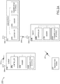
- FIG. 2A illustrates a simplified block diagram of a system 200 for determining a geographical location of a transmitting device 202 using differential time-of-arrival (TOA) estimation techniques, in accordance with one or more embodiments of the present disclosure.
- the system 200 may include a transmitting device 202, two or more sensors 204a, 204b, and a concentrator device 214.
- system 200 may be configured to perform differential time-of-arrival (TOA) techniques in order to estimate and/or determine a geographical position of the transmitting device 202.
- the sensors 204a, 204b may be configured to receive an emitter signal 201 from the transmitting device 202.
- the transmitting device 202 may include any emitter or transmitting device known in the art.
- transmitting device 202 may include a radio frequency (RF) transmitting device.
- RF radio frequency
- transmitting device 202 may include, but is not limited to, an acoustic transmitting device, a radar device, and the like.
- the emitter signals 201 may include any signals known in the art (e.g., RF signals, acoustic signals, radar signals, seismic signals, and the like).
- the first sensor 204a and the second sensor 204b may be located in different geographical positions.
- the concentrator device 214 may be located in a different geographical position as the first sensor 204a, and the second sensor 204b.
- the concentrator device 214 and each sensor 204 of the two or more sensors 204a, 204b may include, but is not limited to, a respective antenna 206 (e.g., antenna 206a, 206b, 206c), a respective controller 208 (e.g., controller 208a, 208b, 208c, etc.), a respective memory 210 (e.g., memory 210a, 210b, 210c, etc.), and a respective communication interface 212 (e.g., communication interface 212a, 212b, 212c, etc.).
- system 200 may include any number of sensors 204a-204n configured to receive emitter signals 201 from the transmitting device 202.
- the antenna 206a, 206b of the sensors 204a, 204b may be configured to receive emitter signals 201 from the transmitting device 202. Additionally, the antenna 206a, 206b of the sensors 204a, 204b may be configured to transmit signals 203a, 203b. In this regard, the antenna 206c of the concentrator device 214 may be configured to receive signals 203a, 203b from the sensors 204a, 204b.
- a sensor 204a, 204b may include a plurality of antennas configured to receive and/or transmit signals on one or more frequency bands. For example, the first sensor 204a may include a first antenna configured to receive emitter signals 201 on a first frequency band, and a second antenna configured to transmit signals 203a on a second frequency band.
- the controller 206a, 206b, 206c provides processing functionality for at least the respective sensor 204a, 204b and/or concentrator device 214 and can include any number of processors, micro-controllers, circuitry, field programmable gate array (FPGA) or other processing systems, and resident or external memory for storing data, executable code, and other information accessed or generated by the sensor 204a, 204b.
- the controller 208a, 208b, 208c can execute one or more software programs embodied in a non-transitory computer readable medium (e.g., memory 210a, 210b, 210c) that implement techniques described herein.
- the controller 208a, 208b, 208c is not limited by the materials from which it is formed or the processing mechanisms employed therein and, as such, can be implemented via semiconductor(s) and/or transistors (e.g., using electronic integrated circuit (IC) components), and so forth.
- semiconductor(s) and/or transistors e.g., using electronic integrated circuit (IC) components
- the memory 210a, 210b, 210c can be an example of tangible, computer-readable storage medium that provides storage functionality to store various data and/or program code associated with operation of the concentrator device 214/sensor 204a, 204b/controller 208a, 208b, such as software programs and/or code segments, or other data to instruct the controller 208a, 208b, 208c and possibly other components of the concentrator 214/sensor 204a, 204b, to perform the functionality described herein.
- the memory 210a, 210b, 210c can store data, such as a program of instructions for operating the concentrator device 214/sensor 204a, 204b, including its components (e.g., controller 208a, 208b, 208c, communication interface 212a, 212b, 212c, etc.), and so forth.
- data such as a program of instructions for operating the concentrator device 214/sensor 204a, 204b, including its components (e.g., controller 208a, 208b, 208c, communication interface 212a, 212b, 212c, etc.), and so forth.
- controller 208a, 208b, 208c e.g., controller 208a, 208b, 208c, communication interface 212a, 212b, 212c, etc.
- the memory 210a, 210b, 210c can be integral with the controller 208a, 208b, 208c, can comprise stand-alone memory, or can be a combination of both
- memory 210a, 210b, 210c can include removable and non-removable memory components, such as random-access memory (RAM), read-only memory (ROM), flash memory (e.g., a secure digital (SD) memory card, a mini-SD memory card, and/or a micro-SD memory card), solid-state drive (SSD) memory, magnetic memory, optical memory, universal serial bus (USB) memory devices, hard disk memory, external memory, and so forth.
- RAM random-access memory
- ROM read-only memory
- flash memory e.g., a secure digital (SD) memory card, a mini-SD memory card, and/or a micro-SD memory card
- SSD solid-state drive
- magnetic memory magnetic memory
- optical memory optical memory
- USB universal serial bus
- the communication interface 212a, 212b, 212 can be operatively configured to communicate with components of the concentrator device 214/sensor 204a, 204b.
- the communication interface 212a, 212b, 212c can be configured to retrieve data from the controller 208a, 208b, 208c, or other devices, transmit data for storage in the memory 210a, 210b, 210c, retrieve data from storage in the memory 210a, 210b, 210c, and so forth.
- the communication interface 212a, 212b, 212c can also be communicatively coupled with the controller 208a, 208b, 208c, to facilitate data transfer between components of the concentrator device 214, sensor 204a, 204b, and the controller 208a, 208b, 208c. It should be noted that while the communication interface 212a, 212b, 212c, is described as a component of the concentrator device 214/sensor 204a, 204b, one or more components of the communication interface 212a, 212b, 212c, can be implemented as external components communicatively coupled to the concentrator device 214/sensor 204a, 204b via a wired and/or wireless connection.
- the concentrator device 214/sensor 204a, 204b can also include and/or connect to one or more input/output (I/O) devices.
- the concentrator device 214/sensor 204a, 204b includes or is coupled to a transmitter, receiver, transceiver, physical connection interface, or any combination thereof.
- the communication interface 212a, 212b, 212c of the concentrator device 214/sensor 204a, 204b may be configured to communicatively couple to additional component of the system 200 using any wireless communication techniques known in the art including, but not limited to, GSM, GPRS, CDMA, EV-DO, EDGE, WiMAX, 3G, 4G, 4G LTE, 5G, WiFi protocols, LoRa, and the like.
- the controller 208a, 208b of a sensor 204a, 204b is configured to carry out various steps and functions of the present disclosure.
- the controller 208a, 208b of the sensors 204a, 204b may be configured to: receive an emitter signal 201 from the communication interface 212a, 212b; store each emitter signal 201 in memory 210a, 120b; demodulate each emitter signal 201 to generate a demodulated sequence of the emitter signal 201; correlate the demodulated sequence and the emitter signal 201 to generate a time-of-arrival (TOA) estimate of the emitter signal 201; and transmit the demodulated sequence and the TOA estimate to the concentrator device 214 via the communication interface 212a, 212b and signals 203a, 203b.
- TOA time-of-arrival
- the controller 208c of the concentrator device 214 is configured to carry out various steps and functions of the present disclosure.
- the controller 208c of the concentrator device 214 may be configured to: receive a first demodulated sequence and a first TOA estimate ( TOA 1 ) from a first sensor 204a; receive a second demodulated sequence and a second TOA estimate ( TOA 2 ), from a second sensor 204b; determine a first arbitrary timing offset ( ATO 1 ) between the first demodulated sequence and the second demodulated sequence; and determine a first differential TOA estimate ( TOA Diff 1 ) between the first sensor 204a and the second sensor 204b based on the first TOA estimate ( TOA 1 ), the second TOA estimate ( TOA 2 ), and the arbitrary timing offset ( ATO 1 ).
- FIG. 3A illustrates a flowchart of a method 300 for determining a geographical location of a transmitting device using differential time-distance-of-arrival (TOA) estimation techniques, in accordance with one or more embodiments of the present disclosure.
- TOA differential time-distance-of-arrival
- steps of method 300 may be configured to take place on/within varying components of system 200.
- steps 302-314 may be carried out by the first sensor 204a and the second sensor 204b respectively, whereas step 318-322 may be carried out by the concentrator device 214.
- signals are received by a first sensor and a second sensor.
- a transmitting device 202 may transmit an emitter signal 201.
- the controllers 208a, 208b may then be configured to receive the emitter signal 201 from the communication interface 212a, 212b, wherein the first controller 208a is configured to receive emitter signal 201, and the second controller 208b is configured to receive emitter signal 201.
- the first sensor 204a and the second sensor 204b may be configured to store the emitter signal 201 in memory 210a, 120b.
- the sensors 204a, 204b may include any sensor device known in the art configured to receive emitter signals 201.
- the controllers 208a, 208b may be configured to digitize the received emitter signals 201 in order to perform digital processing and/or signal recognition.
- the controllers 208a, 208b may be configured to digitize the received emitter signals and store the digitized signals in memory 210a, 210b.
- embodiments of the present disclosure may be carried out by any mix of analog and/or digital processing.
- the first sensor 204a and the second sensor 204b may be spatially separated such that they are located in geographically different positions. It is contemplated herein that the sensors 204a, 204b may be stationary or mobile. In embodiments, the geographical positions of the first sensor 204a and the second sensor 204b may be known. For example, with stationary sensors 204a, 204b, the geographical position of each sensor 204a, 204b may be pre-defined and known. By way of another example, the first sensor 204a and the second sensor 204b may include geographical positioning units (e.g., Global Positioning System (GPS) units, Global Navigation Satellite System (GNSS) units, and the like) configured to determine a geographical position of each sensor 204a, 204b.
- geographical positioning units e.g., Global Positioning System (GPS) units, Global Navigation Satellite System (GNSS) units, and the like
- each sensor 204a, 204b may be stored in memory 210a, 210b.
- the first sensor 204a and the second sensor 204b may be configured to run the same internal clock such that the internal clocks of the first sensor 204a and the second sensor 204b are identical.
- step 304a, 304b signal detection is performed by each of the sensors.
- the first controller 208a and the second controller 208b may be configured to determine when a signal (e.g., emitter signal 201) is present and received by the respective sensors 204a, 204b.
- signal detection in steps 304a, 304b may be carried out using any techniques known in the art. For example, signal detection may be performed by radiometric detection, power detection, and the like.
- method 300 may proceed to steps 306a and 306b.
- modulation recognition is performed.
- the sensors 204a, 204b may not know what modulation technique will be employed by the transmitting device 202. Accordingly, during modulation recognition, the controller 208a, 208b may be configured to determine the type of modulation employed by the transmitting device 202 when transmitting the emitter signal 201.
- the controller 208a, 208b may be configured to identify any modulation technique known in the art including, but not limited to, minimum-shift keying (MSK), phase-shift keying (PSK), amplitude-shift keying (ASK), decision feedback differential modulation (DFDM), binary modulation, and the like.
- steps 308a, 308b demodulation is carried out on the emitter signals to generate a demodulated sequence.
- the first controller 208a may be configured to demodulate the emitter signal 201 to generate a first demodulated sequence
- the second controller 208b may be configured to demodulate the emitter signal 201b to generate a second demodulated sequence.
- the controller 208a, 208b may be configured to store the generated demodulated sequences in memory 210a, 210b.
- the controller 208a, 208b may be configured to retrieve signal values (e.g., a demodulated sequence) of the carrier signal of the emitter signal 201.
- signal values e.g., a demodulated sequence
- the demodulated sequence may include a sequence of "0"s and "1"s. It is noted herein that the controller 208a, 208b may be configured to generate a demodulated sequence despite the existence of bit errors in the received emitter signal 201.
- the controller 208a, 208b may be configured to perform "blind demodulation.”
- Blind demodulation may be used throughout the present disclosure to refer to demodulation carried out without the aid of known reference sequences in the modulated signal (e.g., emitter signal 201).
- steps 304a, 304b, steps 306a, 306b, and steps 308a, 308b may be combined into a single step.
- the controller 208a, 208b know which type of modulation technique will be implemented by the transmitting device 202, signal detection (steps 304a, 304b), modulation recognition (steps 306a, 306b), and demodulation (steps 308a, 308b) may be carried out substantially simultaneously in a single step.
- steps 310a, 310b cross-correlation is performed between the received emitter signals and the generated demodulation sequences.
- the controller 208a, 208b may be configured to receive the originally received emitter signal 201 and the demodulated sequence generated in steps 308a, 308, and perform cross-correlation between the emitter signal 201 and the demodulated sequence. It is noted herein that the demodulated sequence and the data associated with the originally received emitter signal 201 may be retrieved from memory 210a, 210b.
- the controller 208a, 208b may be configured to cross-correlate the emitter signal 201 and the demodulated sequence in order to perform peak detection of signal intensity (e.g., signal magnitude, signal power) over time in order to determine a time-of-arrival (TOA) of the emitter signal 201.
- the controller 208a, 208b may be configured to determine a peak in a graph of signal intensity (e.g., signal magnitude, signal power) as a function of time as the TOA of the emitter signal 201.
- time-of-arrival (TOA) estimation is performed.
- the controller 208a, 208b may be configured to determine a peak in a graph of signal intensity (e.g., signal magnitude, signal power) vs. time as the TOA estimate of the emitter signal 201. Due to the fact that the first sensor 204a and the second sensor 204b are located in geographically different positions, the TOA estimate of the first sensor 204a ( TOA 1 ) may be different from the TOA estimate of the second sensor 204b ( TOA 2 ).
- the first controller 208a may generate a first TOA estimate ( TOA 1 ), and the second controller 208b may generate a second TOA estimate ( TOA 2 ), wherein the second TOA estimate ( TOA 2 ) is different from the first TOA estimate ( TOA 1 ).
- the controller 208a, 208b may be configured to store the generated first TOA estimate ( TOA 1 ) and the generated second TOA estimate ( TOA 2 ) in memory 210a, 210b.
- the first TOA estimate ( TOA 1 ) and the second TOA estimate ( TOA 2 ) are transmitted to the concentrator device 214.
- the first demodulated sequence and the second demodulated sequence are transmitted to the concentrator device 214.
- the first controller 208a may be configured to retrieve the first demodulated sequence and the first TOA estimate ( TOA 1 ) from memory 210a, and transmit the first demodulated sequence and the first TOA estimate ( TOA 1 ) to the concentrator device 214.
- the second controller 208b may be configured to retrieve the second demodulated sequence and the second TOA estimate ( TOA 2 ) from memory 210b, and transmit the second demodulated sequence and the second TOA estimate ( TOA 2 ) to the concentrator device 214.
- the concentrator device 214 may be located in a geographical position which is different from the geographical positions of the first sensor 204a and the second sensor 204b.
- the first demodulated sequence, second demodulated sequence, first TOA estimate ( TOA 1 ), and second TOA estimate ( TOA 2 ) may be transmitted via a hardwired communication network or a wireless communication network.
- system 200 and method 300 may significantly reduce the resolution of data which must be transmitted by the sensors 204a, 204b.
- steps 104a, 104b required high-resolution sample streams to be transmitted over a wireless network. These high-resolution sample streams require extremely high bandwidth and throughput communication systems which far exceed the capabilities of most wireless networks.
- steps 314a, 314b, 316a, and 316b may dramatically reduce the resolution and required throughput of the transmitted data in method 300.
- transmission of low-resolution demodulated sequences and TOA estimates may significantly reduce the burden placed on the wireless network.
- steps 314a, 314b, 316a, and 316b of method 300 may significantly reduce the requisite bandwidth and throughput of the associated network, which is essential for wireless networks.
- the differential TOA estimation technique of method 300 requires only the low-resolution demodulated sequences and TOA estimates (e.g., TOA 1 , TOA 2 ) to be transmitted over a communication network, whereas the conventional TDOA estimation techniques require high-resolution sample streams to be transmitted.
- the differential TDOA estimation approach may reduce the required connectivity/throughput of the communication network by more than an order of magnitude.
- the effective data stream is 32 Mbps for method 100 and approximately 1 Mbps for method 300. Accordingly, embodiments of the present disclosure may reduce the required data rate by a factor of thirty-two for some emitter signals 201.
- the required data rate required to transmit the demodulated sequences in steps 316a, 316b may be further reduced by transmitting only a portion of the demodulated sequences, rather than the entirety of each demodulated sequence.
- the first controller 208a may be configured to retrieve the first demodulated sequence from memory 210a, truncate the demodulated sequence, store the truncated demodulated sequence in memory 210a, and transmit the truncated demodulated sequence to the concentrator device 214 via communication interface 212a. It is noted herein that the demodulated sequences transmitted in steps 316a, 316b need only be long enough to enable alignment detection and timing offset determination in subsequent steps of method 300.
- the first sensor 204a and the second sensor 204b may be configured to transmit other information/data in addition to the demodulated sequences and TOA estimates (e.g., TOA 1 , TOA 2 ) transmitted in steps 314a, 314b, 216a, and 316b.
- the controller 208a, 208b may be configured to determine a signal-to-noise ratio (SNR ) value (e.g., SNR 1 , SNR 2 ) of the emitter signal 201 at each respective sensor 204a, 204b and store the determined SNR values (e.g., SNR 1 , SNR 2 ) in memory 210a, 210b.
- SNR signal-to-noise ratio
- the controller 208a, 208b may be configured to transmit the determined SNR values, via communication interface 212a, 212b, to the concentrator device 214.
- the concentrator device 214 may be configured to receive a first signal-to-noise ratio ( SNR 1 ) associated with the first sensor 204a and a second signal-to-noise ratio ( SNR 2 ) associated with the second sensor 204b.
- the concentrator device 214 may be configured to use the received SNR values in subsequent steps in order to weigh respective differential TOA estimates during geographical position processing, as will be described in further detail herein.
- the controller 208a, 208b may be configured to transmit determined geographical positions of the respective sensors 204a, 204b in addition to the transmitted demodulated sequences and TOA estimates (e.g., TOA 1 , TOA 2 ) .
- the sensors 204a, 204b may include GPS units configured to determine and store a geographical position of the respective sensor 204a, 204b in memory 210a, 210b.
- the controller 208a, 208b may then be configured to transmit the determined geographical positions, via communication interface 212a, 212b, to the concentrator device 214.
- the concentrator device 214 performs alignment detection, and an arbitrary timing offset ( ATO ) is determined based on the alignment detection.
- the first sensor 204a and the second sensor 204b may be located in geographically different positions, and may therefore receive the emitter signal 201 at different times. Reception of the emitter signal 201 at slightly different times may therefore result in an arbitrary timing offset ( ATO ) between the first demodulated sequence generated by the first sensor 204a and the second demodulated sequence generated by the second sensor 204b.
- the controller 208c of the concentrator device 214 may be configured to determine an arbitrary timing offset ( ATO ) between the first demodulated sequence and the second demodulated sequence.
- the controller 208c is configured to store the generated ATO in memory.
- an arbitrary phase shift/phase offset may exist between the first demodulated sequence and the second demodulated sequence.
- the first controller 208a may generate a first demodulated sequence including a series of "0"s and "1"s. Due to the fact that the sensors 204a, 204b may be performing blind demodulation, the second controller 208a may generate a second demodulated sequence including a series of "0"s and "1”s wherein the "0"s and "1”s are flipped as compared to the first demodulated sequence.
- This arbitrary phase shift may be a result of blind demodulation.
- controller 208c may be configured to ignore an arbitrary phase offset and/or adjust a demodulated sequence in order to remove effects of the arbitrary phase offset (e.g., adjust the arbitrary phase offset) when carrying out alignment detection and ATO determination in step 318.
- a differential time-of-arrival (TOA) estimate is generated.
- the controller 208c of the concentrator device 214 may be configured to determine a differential TOA estimate ( TOA Diff ) between the first sensor 204a and the second sensor 204b based on the first TOA estimate ( TOA 1 ) received by the first sensor 204a (step 314a), the second TOA estimate ( TOA 2 ) received by the second sensor 204b (step 314b), and the determined arbitrary timing offset ( ATO ).
- the differential TOA estimate ( TOA Diff ) between the first sensor 204a and the second sensor 204b may be regarded as a single baseline between the first sensor 204a and the second sensor 204b.
- the controller 208c may be configured to determine the differential TOA estimate ( TOA Diff ) by finding a difference between the first TOA estimate ( TOA 1 ) and the second TOA estimate ( TOA 2 ), and adjusting the resulting difference by the arbitrary timing offset ( ATO ).
- a geographical position of the transmitting device is determined and/or estimated.
- the controller 208c of the concentrator device 214 may be configured to determine a geographical position estimate of the transmitting device 202 based at least on a first differential TOA estimate ( TOA Diff 1 ) between the first sensor 204a and the second sensor 204b.
- the controller 208c may be configured to determine a geographical position estimate of the transmitting device 202 based at least on a determined geographical position of the first sensor 204a, a determined geographical position of the second sensor 204b, and the first differential TOA estimate ( TOA Diff 1 ).
- determining the geographical position of the transmitting device 202 may be carried out using multiple baselines (e.g., multiple differential TOA estimates ( TOA Diff )) between multiple pairs of sensors 204a-204n.
- the controller 208c may be configured to determine a second differential TOA estimate ( TOA Diff 2 ) between the third sensor 204c and a fourth sensor 204d, wherein determining the second differential TOA estimate ( TOAD iff 2 ) is carried out in the same manner as determining the first differential TOA estimate ( TOA Diff 1 ).
- the controller 208c may be configured to determine a geographical position estimate of the transmitting device 202 based at least on the first differential TOA estimate ( TOA Diff 1 ) and the second differential TOA estimate ( TOA Diff 2 ).
- TOA Diff 3 ( TOA 3 - TOA 1 ) - ATO 3
- ATO 3 is an arbitrary timing offset between demodulated sequences of the first sensor 204a and the third sensor 204c.
- the controller 208c may be configured to determine a geographical position estimate of the transmitting device 202 by weighting differential TOA estimates between sensors 204a-204n based on the determined SNR values of respective sensors. For example, the controller 208c may be configured to determine a geographical position estimate of the transmitting device 202 using a first differential TOA estimate ( TOA Diff 1 ) between a first sensor 204a and a second sensor 204b, a second differential TOA estimate ( TOA Diff 2 ) between a third sensor 204a and a fourth sensor 204d, and a third differential TOA estimate ( TOA Diff 3 ) between the first sensor 204a and the third sensor 204c.
- a first differential TOA estimate TOA Diff 1
- TOA Diff 2 second differential TOA estimate
- TOA Diff 3 third differential TOA estimate
- the concentrator device 214 may further receive SNR values associated with each sensor 204a-204d (e.g., SNR 1 , SNR 2 , SNR 3 , SNR 4 ) . If the SNR value of the first sensor 204a (e.g., SNR 1 ) is lower than that of the second sensor 204b, third sensor 204c, and fourth sensor 204d, the concentrator device 214 may be configured to weigh the first differential TOA estimate ( TOA Diff 1 ) and the third differential TOA estimate ( TOA Diff 3 ) less than the second differential TOA estimate ( TOA Diff 2 ) when determining the geographical position of the transmitting device 202.
- SNR values associated with each sensor 204a-204d e.g., SNR 1 , SNR 2 , SNR 3 , SNR 4 . If the SNR value of the first sensor 204a (e.g., SNR 1 ) is lower than that of the second sensor 204b, third sensor 204c, and fourth sensor
- FIG. 2A and FIG. 3A are shown and described in the context of various functions being performed on a first sensor 204a, a second sensor 204b, and a concentrator device 214, this is not to be regarded as a limitation of the present disclosure.
- a sensor 204 may be configured to carry out the functions of the concentrator device 214.
- the first sensor 204a or the second sensor 204b may function as the concentrator device 214.
- the concentrator device 214 includes one of the sensors 204a, 204b. This may be further understood with reference to FIG. 2B .
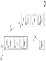
- FIG. 2B illustrates a simplified block diagram of a system 200 for determining a geographical location of a transmitting device 202 using differential time-of-arrival (TOA) estimation techniques, in accordance with one or more embodiments of the present disclosure. It is noted herein that any description associated with system 200 illustrated in FIG. 2A may be regarded as applying to system 200 illustrated in FIG. 2B , unless noted otherwise herein.
- TOA differential time-of-arrival
- the system 200 may include a transmitting device 202, a first sensor 204a, and a second sensor 204b, wherein the first sensor 204a and the second sensor 204b are communicatively coupled.
- the first sensor 204a may be configured to transmit signals 205 to the second sensor 204b to carry out various steps/functions of the present disclosure.
- the controller 208b of the second sensor 204b depicted in FIG. 2B may be configured to carry out the functions of the controller 208c of the concentrator device 214 shown and described in FIGS. 2A and 3A . This may be further understood with reference to FIG. 3A .
- FIG. 3B illustrates a flowchart of a method 300 for determining a geographical location of a transmitting device 202 using differential time-distance-of-arrival (TOA) estimation techniques, in accordance with one or more embodiments of the present disclosure. It is noted herein that any description associated with method 300 illustrated in FIG. 3A may be regarded as applying to method 300 illustrated in FIG. 3B , unless noted otherwise herein.
- TOA differential time-distance-of-arrival
- steps which were previously carried out by the concentrator device 214 may instead be carried out by a sensor 204.
- step 318-322 of method 300 were shown and described as being carried out by the concentrator device 214.
- step 318-322 of method 300 are shown and described as being carried out by the second sensor 204b.
- using the second sensor 204b as the concentrator device 214 may reduce the amount of data which must be transmitted through the communication network. For example, as shown in FIG. 3B , transmitting the second demodulated sequence and the second TOA estimate ( TOA 2 ) from the second sensor 204b to the concentrator device 214 may be omitted due to the fact that the functions of the concentrator device 214 are being carried out by the second sensor 204b.
- embodiments of the methods disclosed herein may include one or more of the steps described herein. Further, such steps may be carried out in any desired order and two or more of the steps may be carried out simultaneously with one another. Two or more of the steps disclosed herein may be combined in a single step, and in some embodiments, one or more of the steps may be carried out as two or more sub-steps. Further, other steps or sub-steps may be carried in addition to, or as substitutes to one or more of the steps disclosed herein.
Landscapes
- Physics & Mathematics (AREA)
- Engineering & Computer Science (AREA)
- General Physics & Mathematics (AREA)
- Radar, Positioning & Navigation (AREA)
- Remote Sensing (AREA)
- Computer Networks & Wireless Communication (AREA)
- Signal Processing (AREA)
- Position Fixing By Use Of Radio Waves (AREA)
- Mobile Radio Communication Systems (AREA)
Applications Claiming Priority (1)
| Application Number | Priority Date | Filing Date | Title |
|---|---|---|---|
| US16/506,342 US11378645B2 (en) | 2019-07-09 | 2019-07-09 | System and method for blind differential time-of-arrival estimation |
Publications (1)
| Publication Number | Publication Date |
|---|---|
| EP3764121A1 true EP3764121A1 (fr) | 2021-01-13 |
Family
ID=71575069
Family Applications (1)
| Application Number | Title | Priority Date | Filing Date |
|---|---|---|---|
| EP20185059.1A Withdrawn EP3764121A1 (fr) | 2019-07-09 | 2020-07-09 | Système et procédé d'estimation différentielle aveugle de temps d'arrivée |
Country Status (2)
| Country | Link |
|---|---|
| US (1) | US11378645B2 (fr) |
| EP (1) | EP3764121A1 (fr) |
Families Citing this family (1)
| Publication number | Priority date | Publication date | Assignee | Title |
|---|---|---|---|---|
| FR3130043B1 (fr) * | 2021-12-02 | 2023-12-29 | Univ Lille | détecteur de coïncidence pour localiser une source |
Citations (4)
| Publication number | Priority date | Publication date | Assignee | Title |
|---|---|---|---|---|
| GB2330716A (en) * | 1997-10-27 | 1999-04-28 | Motorola Ltd | Position determination using a reference transmitter |
| EP1014105A2 (fr) * | 1998-12-18 | 2000-06-28 | Lucent Technologies Inc. | Procédé et dispositif de positionnement d'une unité sans fil |
| US20140073352A1 (en) * | 2012-09-11 | 2014-03-13 | Qualcomm Incorporated | Method for precise location determination |
| US20150071092A1 (en) * | 2013-09-07 | 2015-03-12 | Qualcomm Incorporated | Blind search for network positioning reference signal (prs) configuration parameters |
Family Cites Families (4)
| Publication number | Priority date | Publication date | Assignee | Title |
|---|---|---|---|---|
| US5327144A (en) * | 1993-05-07 | 1994-07-05 | Associated Rt, Inc. | Cellular telephone location system |
| US6047192A (en) * | 1996-05-13 | 2000-04-04 | Ksi Inc. | Robust, efficient, localization system |
| US7239876B2 (en) * | 2001-09-06 | 2007-07-03 | Motorola, Inc. | Method for increased location receiver sensitivity |
| US10775510B2 (en) * | 2016-06-06 | 2020-09-15 | Brian G. Agee | Blind despreading of civil GNSS signals for resilient PNT applications |
-
2019
- 2019-07-09 US US16/506,342 patent/US11378645B2/en active Active
-
2020
- 2020-07-09 EP EP20185059.1A patent/EP3764121A1/fr not_active Withdrawn
Patent Citations (4)
| Publication number | Priority date | Publication date | Assignee | Title |
|---|---|---|---|---|
| GB2330716A (en) * | 1997-10-27 | 1999-04-28 | Motorola Ltd | Position determination using a reference transmitter |
| EP1014105A2 (fr) * | 1998-12-18 | 2000-06-28 | Lucent Technologies Inc. | Procédé et dispositif de positionnement d'une unité sans fil |
| US20140073352A1 (en) * | 2012-09-11 | 2014-03-13 | Qualcomm Incorporated | Method for precise location determination |
| US20150071092A1 (en) * | 2013-09-07 | 2015-03-12 | Qualcomm Incorporated | Blind search for network positioning reference signal (prs) configuration parameters |
Non-Patent Citations (1)
| Title |
|---|
| CHAO SHEN ET AL: "Parameter estimation of digital communication signal", 2014 IEEE WORKSHOP ON ADVANCED RESEARCH AND TECHNOLOGY IN INDUSTRY APPLICATIONS (WARTIA), IEEE, 29 September 2014 (2014-09-29), pages 1080 - 1083, XP032697654, DOI: 10.1109/WARTIA.2014.6976464 * |
Also Published As
| Publication number | Publication date |
|---|---|
| US20210247480A1 (en) | 2021-08-12 |
| US11378645B2 (en) | 2022-07-05 |
Similar Documents
| Publication | Publication Date | Title |
|---|---|---|
| US12553978B2 (en) | Proactive link acquisition (spatial awareness) | |
| US20230288518A1 (en) | Robust addressing schema for spatial awareness via doppler null scanning (dns) | |
| JP7008968B2 (ja) | マルチアンテナ送信機の出発角度の識別 | |
| EP2959601B1 (fr) | Procédé et appareil pour communications de données focalisées | |
| CN110208737B (zh) | 一种超短波双通道宽带测向系统及门限判定测向方法 | |
| US10845486B2 (en) | Satellite positioning system navigation bit aiding | |
| EP2058670B1 (fr) | Suppression d'effets à trajets multiples pour signal SPS reçu | |
| CN105676199B (zh) | 基于通信/雷达一体化的单通道lte雷达系统 | |
| US10182315B2 (en) | Identifying angle of departure of multi-antenna transmitters | |
| EP2926473B1 (fr) | Détection d'un déphasage cyclique à l'aide d'un classificateur | |
| US8948238B2 (en) | Handling complex signal parameters | |
| EP2984501A1 (fr) | Système et procédé associés à un retour de canal de temps de vol de localisation | |
| US12578414B2 (en) | Wireless communication systems and methods | |
| Peters et al. | A Doppler correcting software defined radio receiver design for satellite communications | |
| Kang et al. | Analysis of the maximum correlation peak value and RSRQ in LTE signals according to frequency bands and sampling frequencies | |
| EP3764121A1 (fr) | Système et procédé d'estimation différentielle aveugle de temps d'arrivée | |
| US20210368298A1 (en) | Time-domain processing for positioning signals | |
| WO2017181448A1 (fr) | Procédé, appareil, et système de traitement d'informations, et support de stockage informatique | |
| CN210323343U (zh) | 一种超短波双通道宽带测向系统 | |
| US20200278455A1 (en) | Gnss device with improved cross-correlation immunity | |
| US12501294B2 (en) | Radio frequency scanner system and method for mobile network testing | |
| US9054856B2 (en) | Processing samples of a received RF signal | |
| JP2005195347A (ja) | 方探センサ及び電波発射源位置推定システム | |
| EP4145712A1 (fr) | Système et procédé de balayage de fréquence radio pour le test de réseau mobile | |
| EP3112892A1 (fr) | Procédé et appareil pour géo-localisation d'émetteur sur des plateformes mobiles |
Legal Events
| Date | Code | Title | Description |
|---|---|---|---|
| PUAI | Public reference made under article 153(3) epc to a published international application that has entered the european phase |
Free format text: ORIGINAL CODE: 0009012 |
|
| STAA | Information on the status of an ep patent application or granted ep patent |
Free format text: STATUS: THE APPLICATION HAS BEEN PUBLISHED |
|
| AK | Designated contracting states |
Kind code of ref document: A1 Designated state(s): AL AT BE BG CH CY CZ DE DK EE ES FI FR GB GR HR HU IE IS IT LI LT LU LV MC MK MT NL NO PL PT RO RS SE SI SK SM TR |
|
| AX | Request for extension of the european patent |
Extension state: BA ME |
|
| STAA | Information on the status of an ep patent application or granted ep patent |
Free format text: STATUS: REQUEST FOR EXAMINATION WAS MADE |
|
| 17P | Request for examination filed |
Effective date: 20210713 |
|
| RBV | Designated contracting states (corrected) |
Designated state(s): AL AT BE BG CH CY CZ DE DK EE ES FI FR GB GR HR HU IE IS IT LI LT LU LV MC MK MT NL NO PL PT RO RS SE SI SK SM TR |
|
| STAA | Information on the status of an ep patent application or granted ep patent |
Free format text: STATUS: EXAMINATION IS IN PROGRESS |
|
| 17Q | First examination report despatched |
Effective date: 20231204 |
|
| STAA | Information on the status of an ep patent application or granted ep patent |
Free format text: STATUS: THE APPLICATION IS DEEMED TO BE WITHDRAWN |
|
| 18D | Application deemed to be withdrawn |
Effective date: 20240605 |