EP3764497A1 - Dispositif d'aide à la protection de disjoncteurs multiples dans un système basse tension - Google Patents
Dispositif d'aide à la protection de disjoncteurs multiples dans un système basse tension Download PDFInfo
- Publication number
- EP3764497A1 EP3764497A1 EP18908601.0A EP18908601A EP3764497A1 EP 3764497 A1 EP3764497 A1 EP 3764497A1 EP 18908601 A EP18908601 A EP 18908601A EP 3764497 A1 EP3764497 A1 EP 3764497A1
- Authority
- EP
- European Patent Office
- Prior art keywords
- circuit breaker
- low
- voltage circuit
- voltage
- communication
- Prior art date
- Legal status (The legal status is an assumption and is not a legal conclusion. Google has not performed a legal analysis and makes no representation as to the accuracy of the status listed.)
- Pending
Links
- 230000006854 communication Effects 0.000 claims abstract description 134
- 230000009977 dual effect Effects 0.000 claims description 6
- 238000012806 monitoring device Methods 0.000 claims description 6
- 238000004092 self-diagnosis Methods 0.000 claims description 5
- 230000002159 abnormal effect Effects 0.000 abstract description 4
- 230000005540 biological transmission Effects 0.000 description 11
- 230000000694 effects Effects 0.000 description 8
- 238000010586 diagram Methods 0.000 description 6
- 238000013500 data storage Methods 0.000 description 3
- 210000003813 thumb Anatomy 0.000 description 3
- 230000007175 bidirectional communication Effects 0.000 description 2
- 230000004807 localization Effects 0.000 description 2
- 230000003245 working effect Effects 0.000 description 1
Images

Classifications
-
- H—ELECTRICITY
- H02—GENERATION; CONVERSION OR DISTRIBUTION OF ELECTRIC POWER
- H02H—EMERGENCY PROTECTIVE CIRCUIT ARRANGEMENTS
- H02H3/00—Emergency protective circuit arrangements for automatic disconnection directly responsive to an undesired change from normal electric working condition with or without subsequent reconnection ; integrated protection
- H02H3/02—Details
- H02H3/05—Details with means for increasing reliability, e.g. redundancy arrangements
-
- H—ELECTRICITY
- H02—GENERATION; CONVERSION OR DISTRIBUTION OF ELECTRIC POWER
- H02H—EMERGENCY PROTECTIVE CIRCUIT ARRANGEMENTS
- H02H1/00—Details of emergency protective circuit arrangements
- H02H1/0061—Details of emergency protective circuit arrangements concerning transmission of signals
- H02H1/0084—Details of emergency protective circuit arrangements concerning transmission of signals by means of pilot wires or a telephone network; watching of these wires
-
- H—ELECTRICITY
- H02—GENERATION; CONVERSION OR DISTRIBUTION OF ELECTRIC POWER
- H02H—EMERGENCY PROTECTIVE CIRCUIT ARRANGEMENTS
- H02H1/00—Details of emergency protective circuit arrangements
- H02H1/0061—Details of emergency protective circuit arrangements concerning transmission of signals
-
- H—ELECTRICITY
- H02—GENERATION; CONVERSION OR DISTRIBUTION OF ELECTRIC POWER
- H02H—EMERGENCY PROTECTIVE CIRCUIT ARRANGEMENTS
- H02H1/00—Details of emergency protective circuit arrangements
- H02H1/0092—Details of emergency protective circuit arrangements concerning the data processing means, e.g. expert systems, neural networks
-
- H—ELECTRICITY
- H02—GENERATION; CONVERSION OR DISTRIBUTION OF ELECTRIC POWER
- H02H—EMERGENCY PROTECTIVE CIRCUIT ARRANGEMENTS
- H02H3/00—Emergency protective circuit arrangements for automatic disconnection directly responsive to an undesired change from normal electric working condition with or without subsequent reconnection ; integrated protection
- H02H3/02—Details
- H02H3/04—Details with warning or supervision in addition to disconnection, e.g. for indicating that protective apparatus has functioned
- H02H3/042—Details with warning or supervision in addition to disconnection, e.g. for indicating that protective apparatus has functioned combined with means for locating the fault
-
- H—ELECTRICITY
- H02—GENERATION; CONVERSION OR DISTRIBUTION OF ELECTRIC POWER
- H02H—EMERGENCY PROTECTIVE CIRCUIT ARRANGEMENTS
- H02H7/00—Emergency protective circuit arrangements specially adapted for specific types of electric machines or apparatus or for sectionalised protection of cable or line systems, and effecting automatic switching in the event of an undesired change from normal working conditions
- H02H7/26—Sectionalised protection of cable or line systems, e.g. for disconnecting a section on which a short-circuit, earth fault, or arc discharge has occured
- H02H7/261—Sectionalised protection of cable or line systems, e.g. for disconnecting a section on which a short-circuit, earth fault, or arc discharge has occured involving signal transmission between at least two stations
- H02H7/262—Sectionalised protection of cable or line systems, e.g. for disconnecting a section on which a short-circuit, earth fault, or arc discharge has occured involving signal transmission between at least two stations involving transmissions of switching or blocking orders
-
- H—ELECTRICITY
- H02—GENERATION; CONVERSION OR DISTRIBUTION OF ELECTRIC POWER
- H02H—EMERGENCY PROTECTIVE CIRCUIT ARRANGEMENTS
- H02H7/00—Emergency protective circuit arrangements specially adapted for specific types of electric machines or apparatus or for sectionalised protection of cable or line systems, and effecting automatic switching in the event of an undesired change from normal working conditions
- H02H7/26—Sectionalised protection of cable or line systems, e.g. for disconnecting a section on which a short-circuit, earth fault, or arc discharge has occured
- H02H7/30—Staggered disconnection
-
- H—ELECTRICITY
- H02—GENERATION; CONVERSION OR DISTRIBUTION OF ELECTRIC POWER
- H02H—EMERGENCY PROTECTIVE CIRCUIT ARRANGEMENTS
- H02H3/00—Emergency protective circuit arrangements for automatic disconnection directly responsive to an undesired change from normal electric working condition with or without subsequent reconnection ; integrated protection
- H02H3/02—Details
- H02H3/06—Details with automatic reconnection
- H02H3/063—Details concerning the co-operation of many similar arrangements, e.g. in a network
-
- H—ELECTRICITY
- H02—GENERATION; CONVERSION OR DISTRIBUTION OF ELECTRIC POWER
- H02H—EMERGENCY PROTECTIVE CIRCUIT ARRANGEMENTS
- H02H3/00—Emergency protective circuit arrangements for automatic disconnection directly responsive to an undesired change from normal electric working condition with or without subsequent reconnection ; integrated protection
- H02H3/26—Emergency protective circuit arrangements for automatic disconnection directly responsive to an undesired change from normal electric working condition with or without subsequent reconnection ; integrated protection responsive to difference between voltages or between currents; responsive to phase angle between voltages or between currents
- H02H3/28—Emergency protective circuit arrangements for automatic disconnection directly responsive to an undesired change from normal electric working condition with or without subsequent reconnection ; integrated protection responsive to difference between voltages or between currents; responsive to phase angle between voltages or between currents involving comparison of the voltage or current values at two spaced portions of a single system, e.g. at opposite ends of one line, at input and output of apparatus
-
- H—ELECTRICITY
- H02—GENERATION; CONVERSION OR DISTRIBUTION OF ELECTRIC POWER
- H02H—EMERGENCY PROTECTIVE CIRCUIT ARRANGEMENTS
- H02H3/00—Emergency protective circuit arrangements for automatic disconnection directly responsive to an undesired change from normal electric working condition with or without subsequent reconnection ; integrated protection
- H02H3/26—Emergency protective circuit arrangements for automatic disconnection directly responsive to an undesired change from normal electric working condition with or without subsequent reconnection ; integrated protection responsive to difference between voltages or between currents; responsive to phase angle between voltages or between currents
- H02H3/36—Emergency protective circuit arrangements for automatic disconnection directly responsive to an undesired change from normal electric working condition with or without subsequent reconnection ; integrated protection responsive to difference between voltages or between currents; responsive to phase angle between voltages or between currents involving comparison of the voltage or current values at corresponding points of different systems, e.g. of parallel feeder systems
-
- H—ELECTRICITY
- H02—GENERATION; CONVERSION OR DISTRIBUTION OF ELECTRIC POWER
- H02H—EMERGENCY PROTECTIVE CIRCUIT ARRANGEMENTS
- H02H7/00—Emergency protective circuit arrangements specially adapted for specific types of electric machines or apparatus or for sectionalised protection of cable or line systems, and effecting automatic switching in the event of an undesired change from normal working conditions
- H02H7/26—Sectionalised protection of cable or line systems, e.g. for disconnecting a section on which a short-circuit, earth fault, or arc discharge has occured
-
- H—ELECTRICITY
- H04—ELECTRIC COMMUNICATION TECHNIQUE
- H04L—TRANSMISSION OF DIGITAL INFORMATION, e.g. TELEGRAPHIC COMMUNICATION
- H04L45/00—Routing or path finding of packets in data switching networks
- H04L45/18—Loop-free operations
-
- H—ELECTRICITY
- H04—ELECTRIC COMMUNICATION TECHNIQUE
- H04L—TRANSMISSION OF DIGITAL INFORMATION, e.g. TELEGRAPHIC COMMUNICATION
- H04L45/00—Routing or path finding of packets in data switching networks
- H04L45/48—Routing tree calculation
Definitions
- the present disclosure relates to an efficient protection assistance device between a plurality of upper and lower circuit breakers in a low-voltage system.
- FIG. 1 is a block diagram showing the configuration thereof.
- the low-voltage system may include an upper power line (PL2) and a lower power line (PL1).
- PL2 upper power line
- PL1 lower power line
- the upper power line (PL2) is a power line close to a power transmission side, that is, a power source side
- the lower power line (PL1) is a power line close to a power receiving side, that is, a load side or an end power user.
- reference numeral DL1 is a first branch line connected between the uppermost power line (not shown) and the upper power line (PL2) to supply power from the uppermost power line to the upper power line (PL2).
- reference numeral DL2 is a second branch line connected between the upper power line (PL2) and the lower power line (PL1) to supply power from the upper power line (PL2) to the lower power line (PL1)
- reference numerals DL3 and DL4 are third branch lines respectively connected between the lower power line (PL1) and a plurality of loads (power consumers) (not shown) to supply power from the lower power line (PL1) to the plurality of loads (power consumers).
- An upper circuit breaker 30 is connected to the first branch line (DL1) in series to open and close the corresponding first branch line (DL1).
- a middle circuit breaker 20 is connected to the second branch line (DL2) in series to open and close the second branch line (DL2).
- Two lower circuit breakers 10-1, 10-2 are connected to the third branch lines (DL3, DL4) in series to open and close the corresponding third branch lines (DL3, DL4), respectively.
- reference numeral SL1 is a first communication line for signal communication between the upper circuit breaker 30 and the middle circuit breaker 20.
- Reference numeral SL2 is a second communication line for signal communication between the middle circuit breaker 20 and the lower circuit breakers 10-1, 10-2.
- Reference numeral SL1a is a first connection signal line for connecting the upper circuit breaker 30 or the middle circuit breaker 20 to the first communication line (SL1) for signal communication
- reference numeral SL2a is a second connection signal line for connecting the middle circuit breaker 20 or the lower circuit breakers 10-1, 10-2 to the second communication line SL2 for signal communication.
- Reference numeral CCL is a common connection line connecting an input terminal and a common terminal to indicate no input.
- reference numeral Z1 is a common terminal
- reference numeral Z2 is a zone selective interlock signal output terminal, which is an output terminal of a zone selective interlock signal for localization of a failure section
- reference numeral Z3 is a common terminal
- reference numeral Z4 is a zone selective interlock signal input terminal
- reference numeral Z5 is a ground fault dedicated input terminal.
- the middle circuit breaker 20 connected on the second branch line (DL2) detects such a failure and performs an automatic circuit breaking (trip) operation to cut off power supply from the upper power line (PL2) to the lower power line (PL1).
- trip automatic circuit breaking
- the lower circuit breakers 10-1, 10-2 that receive power from the lower power line (PL1) and unshown load sides that receive power through the corresponding lower circuit breakers 10-1, 10-2 are in an outage state.
- the middle circuit breaker 20 outputs a zone selective interlock signal for localization of a failure section through the common terminal (Z1) and the zone selective interlock signal output terminal (Z2).
- the upper circuit breaker 30 receives the zone selective interlock signal through the common terminal (Z3), the zone selective interlock signal input terminal (Z4), and the ground fault dedicated input terminal (Z5) to determine that the middle circuit breaker 20 has performed a trip operation.
- the upper circuit breaker 30 that has received a zone selective interlock signal performs the trip operation to cut off power supply from the uppermost power line, which is not shown, to the upper power line (PL2).
- a trip setting time (short time or long time, 0.2 seconds) of the middle circuit breaker 20 is set to be shorter than that (0.3 seconds) of the upper circuit breaker 30 so as to allow the upper circuit breaker 30 to perform a trip operation after the middle circuit breaker 20 first attempts a trip operation.
- a load side (not shown) that receives power through the middle circuit breaker 20, the lower circuit breakers 10-1, 10-2 and the corresponding lower circuit breakers 10-1, 10-2 that receive power supply from the upper power line (PL2) is in an outage state.
- the upper circuit breaker 30 connected to the first branch line (DL1) detects such a failure to perform an automatic circuit breaking (trip) operation so as to cut off power supply from the uppermost power line (not shown) to the upper power line (PL2).
- the protection assistance device of multiple of circuit breakers does not transmit a zone selective interlock signal to the lower circuit breaker, and there is a problem in that the circuit breaker and a load side lower than that must be powered off without any information, that is, a problem in that protection assistance is made in only one direction from the lower side to the upper side.
- the protection assistance device of multiple of circuit breakers must wire 5 signal terminals and 5 signal lines for protection assistance between the upper and lower circuit breakers to increase the number of wirings, and there is a problem in that the occupied wiring space and the wiring cost are excessive and the wiring work takes a long time due to a large number of wirings.
- an aspect of the present disclosure is to solve the foregoing problems of the related art, and to provide a protection assistance device of multiple circuit breakers in a low-voltage system capable of providing protection assistance in both directions from the upper to the lower side or from the lower to the upper side, and minimizing the number of wirings for protection assistance between the plurality of upper and lower circuit breakers.
- An object of the present disclosure may be achieved by providing a protection assistance device of multiple circuit breakers in a low-voltage system, and the protection assistance device may include at least one upper low-voltage circuit breaker connected to a first branch circuit between an uppermost power circuit and an upper power circuit, and configured to have a communication unit; at least one middle low-voltage circuit breaker connected to a second branch circuit between the upper power circuit and a lower power circuit, and configured to have a communication unit; at least one lower voltage circuit breaker connected to a third branch circuit between the lower power circuit and a lowermost power circuit, and configured to have a communication unit; and a communication line that communicably connect the upper low-voltage circuit breaker, the middle low-voltage circuit breaker, and the lower low-voltage circuit breaker; wherein the upper low-voltage circuit breaker, the middle low-voltage circuit breaker, and the lower low-voltage circuit breaker include a controller that transmits a communication packet reporting a trip operation state to at least any one of the predetermined upper lower-
- the upper low-voltage circuit breaker, the middle low-voltage circuit breaker, and the lower low-voltage circuit breaker may be configured to be connected to each other in the form of a closed loop by an ethernet communication line.
- the upper low-voltage circuit breaker, the middle low-voltage circuit breaker, and the lower low-voltage circuit breaker may be connected to a high-speed dual ring communication network.
- the controller may include a program storage unit for storing a rapid spanning tree protocol (RSTP) algorithm.
- RSTP rapid spanning tree protocol
- the protection assistance device may further include a low-voltage circuit breaker additionally connected in the form of an open loop for unidirectional communication to at least any one of the upper low-voltage circuit breaker, the middle low-voltage circuit breaker, and the lower low-voltage circuit breaker, and communicably connected to another external communication network or a higher-level monitoring device.
- the communication packet may include identification information of a destination circuit breaker, trip command information on a destination circuit breaker, status information of a source circuit breaker, and identification information of a source circuit breaker.
- the trip command information may be composed of any one of short time delay trip information, ground fault delay trip information, and long time delay trip information.
- the status information of the source circuit breaker may include operation status information and self-diagnosis information of the source circuit breaker.
- an upper low-voltage circuit breaker, an middle low-voltage circuit breaker and a lower low-voltage circuit breaker may include a controller that transmits a communication packet reporting a trip operation state through a communication line to at least one of the upper low-voltage circuit breaker, the middle low-voltage circuit breaker and the lower low-voltage circuit breaker during the trip operation to enable protection assistance in both directions from the top to the bottom side or from the upper side to the upper side or from the lower side to the upper side, and wiring for protection assistance between the plurality of upper and lower circuit breakers may configured with one or two communication lines, thereby having an effect of minimizing the number of wirings.
- the upper low-voltage circuit breaker, the middle low-voltage circuit breaker and the lower low-voltage circuit breaker may be configured to be connected to each other in a closed loop form by an Ethernet communication line, thereby obtaining an advantage of allowing bidirectional communication from the upper low-voltage circuit breaker to the lower low-voltage circuit breaker or from the lower low-voltage circuit breaker to the upper low-voltage circuit breaker.
- the upper low-voltage circuit breaker, the middle low-voltage circuit breaker, and the lower low-voltage circuit breaker may be connected by a high-speed dual ring communication network, thereby obtaining an effect of allowing bidirectional communication from the upper low-voltage circuit breaker to the lower low-voltage circuit breaker or from the lower low-voltage circuit breaker to the upper low-voltage circuit breaker and allowing communication at high speed.
- the controller may include a program storage unit for storing an RSTP algorithm, thereby obtaining an effect capable of processing to generate, transmit, store, or receive communication packets according to the RSTP protocol.
- a protection assistance device is configured to include an additional low-voltage circuit breaker connected to at least one of the upper low-voltage circuit breaker, the middle low-voltage circuit breaker, and the lower low-voltage circuit breaker in the form of an open loop for unidirectional communication, and the corresponding additionally connected low-voltage circuit breaker may be connected to a network switch or a hub to obtain an effect of transmitting the information of the closed loop network to another communication network or a higher-level monitoring device.
- the communication packet may include identification information of a destination circuit breaker, trip command information on a destination circuit breaker, or status information of a source circuit breaker and identification information of a source circuit breaker, thereby obtaining an effect of discarding a received communication packet when the identification information of the source circuit breaker indicates itself or transferring the received communication packet to an adjacent circuit breaker when the identification information of the destination circuit breaker does not indicate itself.
- the trip command information may be composed of any one of short time delay trip information, ground fault delay trip information, and long time delay trip information, thereby having an effect of requesting a trip operation according to selective protection assistance to the other circuit breaker among a short time delay trip, a ground fault delay trip, and a long time delay trip.
- the status information of the source circuit breaker may include operation status information and self-diagnosis information of the source circuit breaker, thereby having an effect of allowing the destination circuit breaker to know the operation status and self-diagnosis results of the source circuit breaker.
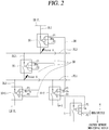
- FIG. 2 is a block diagram showing the configuration of a protection assistance device of multiple circuit breakers in a low-voltage system according to a preferred embodiment of the present disclosure
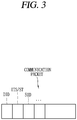
- FIG. 3 is a block diagram of a communication packet according to the present disclosure.
- a protection assistance device may include at least one upper low-voltage circuit breaker 30, at least one middle low-voltage circuit breaker 20, at least one lower low-voltage circuit circuit breaker 10-1, 10-2, and a communication line (DR).
- DR communication line
- the upper low-voltage circuit breaker 30, the middle low-voltage circuit breaker 20, and the lower low-voltage circuit breakers 10-1, 10-2 may include controllers 30a, 20a, 10-1a, 10- 2a.
- reference numeral PL2 indicates an upper power circuit and reference numeral PL1 indicates a lower power circuit.
- the upper power circuit (PL2) is a power line close to a power transmission side, that is, a power source side
- the lower power circuit (PL1) is a power line close to a power receiving side, that is, a load side or an end power user.
- reference symbol UM PL (Uppermost Poser Line) indicates the uppermost power circuit and indicates a power line closest to a power transmission side, that is, a power source side
- reference symbol LM PL (Lowermost Power Line) indicates the lowermost power circuit and indicates a power line closest to a power receiving side, that is, a load side or an end power user.
- the upper low-voltage circuit breaker 30 is connected to the first branch circuit (DL1) between the uppermost power circuit (UM PL) and the upper power circuit (PL2).
- the upper low-voltage circuit breaker 30 may connect the first branch circuit (DL1) (to make the first branch circuit closed) or cut off the first branch circuit (DL1) (to make the first branch circuit open) according to the open/close position (aka ON position, OFF or trip position).
- the upper low-voltage circuit breaker 30 has communication units (P1, P2).
- the upper low-voltage circuit breaker 30 includes a controller 30a.
- the controller 30a may be configured to include a microprocessor or a microcomputer, and may include a control and processing element such as a central processing unit and a program or data storage element such as a memory.
- the controller 30a transmits a communication packet reporting a trip operation state to at least either one of the predetermined middle low-voltage circuit breaker 20 and the low-voltage circuit breaker 10-2 through the communication line (DR).
- the controller 30a includes a program storage unit for storing a rapid spanning tree protocol (RSTP) algorithm (RSTP program) to generate and transmit the communication packet as a communication packet according to a RSTP protocol.
- RSTP rapid spanning tree protocol
- the controller 30a may include a program storage unit for storing a transmission control protocol (TCP) algorithm to generate and transmit the communication packet as a communication packet according to a TCP protocol.
- TCP transmission control protocol
- the communication packet according to the TCP protocol may have a structure including a destination field having identification information of a low-voltage circuit breaker to be transmitted, and a source field having identification information on a transmission source of the communication packet, a sequence number, an acknowledgment number, a check sum field for checking a communication error, and the like.
- the controller 30a may include a program storage unit for storing a user datagram protocol (UDP) algorithm to generate and transmit the communication packet as a communication packet according to a UDP protocol.
- UDP user datagram protocol
- the communication packet according to the UDP protocol may have a structure including a destination field having identification information of a low-voltage circuit breaker to be transmitted, a source field having identification information on a transmission source of the communication packet, and a check thumb field for checking a communication error.
- the middle low-voltage circuit breaker 20 is connected to a second branch circuit (DL2) between the upper power circuit (PL2) and the lower power circuit (PL1).
- DL2 second branch circuit between the upper power circuit (PL2) and the lower power circuit (PL1).
- the middle low-voltage circuit breaker 20 may connect or cut off the second branch circuit (DL2) according to the opening/closing position.
- the middle low-voltage circuit breaker 20 has communication units (P1, P2).
- the middle low-voltage circuit breaker 20 includes a controller 20a.
- the controller 20a may be configured to include a microprocessor or a microcomputer, and may include a control and processing element such as a central processing unit and a program or data storage element such as a memory.
- the controller 20a transmits a communication packet reporting a trip operation state to at least either one of the predetermined upper low-voltage circuit breaker 30 and the low-voltage circuit breaker 10-1 through the communication line (DR).
- the controller 20a may include a program storage unit for storing an RSTP algorithm (RSTP program) to generate the communication packet as a communication packet according to a RSTP protocol.
- RSTP program an RSTP algorithm
- the controller 20a may include a program storage unit for storing a TCP algorithm to generate and transmit the communication packet as a communication packet according to a TCP protocol.
- the communication packet according to the TCP protocol may have a structure including a destination field having identification information of a low-voltage circuit breaker to be transmitted, and a source field having identification information on a transmission source of the communication packet, a sequence number, an acknowledgment number, a check sum field for checking a communication error, and the like
- the controller 20a may include a program storage unit for storing a UDP algorithm to generate and transmit the communication packet as a communication packet according to a UDP protocol.
- the communication packet according to the UDP protocol may have a structure including a destination field having identification information of a low-voltage circuit breaker to be transmitted, a source field having identification information on a transmission source of the communication packet, and a check thumb field for checking a communication error.
- the lower low-voltage circuit breakers 10-1, 10-2 are connected to a third branch circuit (DL3) between the lower power circuit (PL1) and the lowermost power circuit (LM PL).
- DL3 third branch circuit between the lower power circuit (PL1) and the lowermost power circuit (LM PL).
- the lower low-voltage circuit breakers 10-1, 10-2 may connect or cut off the third branch circuit (DL3) according to the open/close position.
- the lower low-voltage circuit breakers 10-1, 10-2 have communication units (P1, P2).
- the lower low-voltage circuit breakers 10-1, 10-2 include controllers 10-1a, 10-2a.
- the controller 10-1a, 10-2a may be configured to include a microprocessor or a microcomputer, and may include a control and processing element such as a central processing unit and a program or data storage element such as a memory.
- the controller 10-1a, 10-2a transmits a communication packet reporting a trip operation state to at least either one of the predetermined middle low-voltage circuit breaker 20 and the low-voltage circuit breaker 10-2 or at least either one of the predetermined upper low-voltage circuit breaker 30 and the low-voltage circuit breaker 10-1 through the communication line (DR).
- the controller 10-1a transmits a communication packet reporting a trip operation state to at least either one of the predetermined middle low-voltage circuit breaker 20 and the lower low-voltage circuit 10-2 through the communication line (DR).
- the controller 10-2a transmits a communication packet reporting a trip operation state to at least either one of the predetermined upper low-voltage circuit breaker 30 and the lower low-voltage circuit 10-1 through the communication line (DR).
- the controller 10-1a, 10-2a may include a program storage unit for storing an RSTP algorithm (RSTP program) to generate the communication packet as a communication packet according to a RSTP protocol.
- RSTP program an RSTP algorithm
- the controller 10-1a, 10-2a may include a program storage unit for storing a TCP algorithm to generate and transmit the communication packet as a communication packet according to a TCP protocol.
- the communication packet according to the TCP protocol may have a structure including a destination field having identification information of a low-voltage circuit breaker to be transmitted, and a source field having identification information on a transmission source of the communication packet, a sequence number, an acknowledgment number, a check sum field for checking a communication error, and the like.
- the controller 10-1a, 10-2a may include a program storage unit for storing a UDP algorithm to generate and transmit the communication packet as a communication packet according to a UDP protocol.
- the communication packet according to the UDP protocol may have a structure including a destination field having identification information of a low-voltage circuit breaker to be transmitted, a source field having identification information on a transmission source of the communication packet, and a check thumb field for checking a communication error.
- the communication line (DR) communicably connects the upper low-voltage circuit breaker 30 and the middle low-voltage circuit breaker 20 and the lower low-voltage circuit breaker 10-1, 10-2.
- the upper low-voltage circuit breaker 30, the middle low-voltage circuit breaker 20 and the lower low-voltage circuit breaker 10-1, 10-2 are configured to be connected to each other in the form of a closed loop by an Ethernet communication line.
- the communication line (DR) may be configured with an Ethernet communication line that connects the upper low-voltage circuit breaker 30, the middle low-voltage circuit breaker 20, and the lower low-voltage circuit breaker 10-1, 10-2 in the form of a closed loop.
- the upper low-voltage circuit breaker 30 and the middle low-voltage circuit breaker 20 and the lower low-voltage circuit breaker 10-1, 10-2 are connected by a high-speed dual ring communication network.
- the communication line (DR) may be composed of a high-speed dual ring communication network that connects the upper low-voltage circuit breaker 30, the middle low-voltage circuit breaker 20, and the lower low-voltage circuit breaker 10-1, 10-2 to each other.
- the communication line (DR) which is a closed loop high-speed dual ring communication network, and therefore, the communication packet transmitted by any one of the upper low-voltage circuit breaker 30, the middle low-voltage circuit breaker 20 and the lower low-voltage circuit breaker 10-1, 10-2 may be transmitted all of the upper low-voltage circuit breaker 30, the middle low-voltage circuit breaker 20 and the lower low-voltage circuit breaker 10-1, 10-2 connected to the communication line (DR).
- a protection assistance device may further include a low-voltage circuit breaker 5 additionally connected in the form of an open loop for unidirectional communication to at least any one of the upper low-voltage circuit breaker, the middle low-voltage circuit breaker, and the lower low-voltage circuit breaker.
- the low-voltage circuit breaker 5 may also include the communication units (P1, P2) and the controller 5a as described above.
- the low-voltage circuit breaker 5 may be connected to a network switch or hub 6 so as to connect the closed loop network to another communication network or a higher-level monitoring device such as a remote supervisory control and data acquisition device (SCADA device), for instance.
- SCADA device remote supervisory control and data acquisition device
- the communication packet may include identification information (DID) of a destination circuit breaker, trip command information on a destination circuit breaker or status information (ITS/ST) of a source circuit breaker, and identification information (SID) of a source circuit breaker.
- DID identification information
- ITS/ST status information
- SID identification information
- the trip command information may be configured as any one of short time delay trip information, ground fault delay trip information, and long time delay trip information.
- the status information (ST) of the source circuit breaker may include the ON or trip/OFF operation status information and self-diagnosis information of the source circuit breaker.
- the middle circuit breaker 20 connected on the second branch line (DL2) detects such a failure and performs an automatic circuit breaking (trip) operation to cut off power supply from the upper power line (PL2) to the lower power line (PL1).
- trip automatic circuit breaking
- the lower circuit breakers 10-1, 10-2 that receive power from the lower power line (PL1) and unshown load sides that receive power through the corresponding lower circuit breakers 10-1, 10-2 are in an outage state.
- the middle circuit breaker 20 transmits communication packets through the communication units (P1, P2).
- the communication packet may include any one of short time delay trip information, ground fault delay trip information, and long time delay trip information, and status information (ST) of the middle circuit breaker 20 as identity information (or address information) of the upper low-voltage circuit breaker 30, identity information (or address information) of the middle circuit breaker 20, and trip command information (trip command data (ITS) for performing a protection assistance operation.
- ST status information
- ST status information
- ITS trip command data
- the upper circuit breaker 30 may receive the communication packet through the communication units (P1, P2) to determine that the middle circuit breaker 20 has performed a trip operation, and perform a trip operation according to the trip command information (ITS).
- the communication units P1, P2
- ITS trip command information
- the middle low-voltage circuit breaker 20 and the lower low-voltage circuit breaker 10-1, 10-2 are communicably connected in the form of a closed loop through the communication line (DR), not only the upper low-voltage circuit breaker 30 but also the lower low-voltage circuit breaker 10-1, 10-2 may receive the communication packet to determine that the middle low-voltage circuit breaker 20 has performed a trip operation, and selectively store the entire communication packet or only predetermined information data (e.g., status information of the middle low-voltage circuit breaker).
- predetermined information data e.g., status information of the middle low-voltage circuit breaker
- the low-voltage circuit breaker 5 may be additionally connected to the lower low-voltage circuit breaker 10-2 in the form of an open loop, and the low-voltage circuit breaker 5 may also transmit and report information (status information, trip command information, etc.) according to the communication packet to another network or a higher-level monitoring device through the hub or network switch 6.
- information status information, trip command information, etc.
- the upper circuit breaker 30 that has received the communication packet performs a delay trip operation according to the trip command information, thereby cutting off power supply from the uppermost power line (not shown) to the upper power line (PL2).
- a load side (not shown) that receives power through the middle circuit breaker 20, the lower circuit breakers 10-1, 10-2 and the corresponding lower circuit breakers 10-1, 10-2 that receive power supply from the upper power line (PL2) is in an outage state.
- the upper circuit breaker 30 connected to the first branch line (DL1) detects such a failure to perform an automatic circuit breaking (trip) operation so as to cut off power supply from the uppermost power line (not shown) to the upper power line (PL2).
- the middle low-voltage circuit breaker 20 and the lower low-voltage circuit breaker 10-1, 10-2 are communicably connected in the form of a closed loop through the communication line (DR), not only the middle low-voltage circuit breaker 20 but also the lower low-voltage circuit breaker 10-1, 10-2 may receive the communication packet to determine that the upper low-voltage circuit breaker 30 has performed a trip operation, and selectively store the entire communication packet or only predetermined information data (e.g., status information of the upper low-voltage circuit breaker).
- predetermined information data e.g., status information of the upper low-voltage circuit breaker
- the upper low-voltage circuit breaker 30, the middle low-voltage circuit breaker 20, and the lower low-voltage circuit breaker 10-1, 10-2 may be provided with a temporary power supply element such as a battery (not shown) to enable the transmission, delivery, reception and storage of the communication packet.
- a temporary power supply element such as a battery (not shown) to enable the transmission, delivery, reception and storage of the communication packet.
- the low-voltage circuit breaker 5 may be additionally connected to the lower low-voltage circuit breaker 10-2 in the form of an open loop, and the low-voltage circuit breaker 5 may also transmit and report information (status information, trip command information, etc.) according to the communication packet to another network or a higher-level monitoring device through the hub or network switch 6.
- information status information, trip command information, etc.
- an upper low-voltage circuit breaker, an middle low-voltage circuit breaker and a lower low-voltage circuit breaker may include a controller that transmits a communication packet reporting a trip operation state through a communication line to at least one of the upper low-voltage circuit breaker, the middle low-voltage circuit breaker and the lower low-voltage circuit breaker during the trip operation to enable protection assistance in both directions from the top to the bottom side or from the upper side to the upper side or from the lower side to the upper side, and wiring for protection assistance between the plurality of upper and lower circuit breakers may configured with one or two communication lines, thereby having an effect of minimizing the number of wirings.
Landscapes
- Physics & Mathematics (AREA)
- Electromagnetism (AREA)
- Engineering & Computer Science (AREA)
- Computer Networks & Wireless Communication (AREA)
- Signal Processing (AREA)
- Artificial Intelligence (AREA)
- Evolutionary Computation (AREA)
- Remote Monitoring And Control Of Power-Distribution Networks (AREA)
- Breakers (AREA)
- Emergency Protection Circuit Devices (AREA)
Applications Claiming Priority (2)
| Application Number | Priority Date | Filing Date | Title |
|---|---|---|---|
| KR1020180026464A KR102087143B1 (ko) | 2018-03-06 | 2018-03-06 | 저압 계통에서 복수의 회로차단기의 보호 협조 장치 |
| PCT/KR2018/014325 WO2019172504A1 (fr) | 2018-03-06 | 2018-11-21 | Dispositif d'aide à la protection de disjoncteurs multiples dans un système basse tension |
Publications (2)
| Publication Number | Publication Date |
|---|---|
| EP3764497A1 true EP3764497A1 (fr) | 2021-01-13 |
| EP3764497A4 EP3764497A4 (fr) | 2021-12-08 |
Family
ID=67847259
Family Applications (1)
| Application Number | Title | Priority Date | Filing Date |
|---|---|---|---|
| EP18908601.0A Pending EP3764497A4 (fr) | 2018-03-06 | 2018-11-21 | Dispositif d'aide à la protection de disjoncteurs multiples dans un système basse tension |
Country Status (6)
| Country | Link |
|---|---|
| US (1) | US11289892B2 (fr) |
| EP (1) | EP3764497A4 (fr) |
| JP (1) | JP7096897B2 (fr) |
| KR (1) | KR102087143B1 (fr) |
| CN (1) | CN111819749B (fr) |
| WO (1) | WO2019172504A1 (fr) |
Families Citing this family (3)
| Publication number | Priority date | Publication date | Assignee | Title |
|---|---|---|---|---|
| KR102652596B1 (ko) * | 2018-08-27 | 2024-04-01 | 엘에스일렉트릭(주) | 양방향 반도체 차단기 |
| DE102020103491A1 (de) * | 2020-02-11 | 2021-08-12 | Dehn Se + Co Kg | Anordnung zur Bewertung des Zustandes und der Qualität von Niederspannungsnetzen |
| JP2023127417A (ja) * | 2022-03-01 | 2023-09-13 | 河村電器産業株式会社 | 回路遮断器及び電路遮断システム |
Family Cites Families (35)
| Publication number | Priority date | Publication date | Assignee | Title |
|---|---|---|---|---|
| US4335437A (en) * | 1980-04-15 | 1982-06-15 | Westinghouse Electric Corp. | Circuit interrupter with energy management functions |
| JPH0832135B2 (ja) * | 1988-06-29 | 1996-03-27 | 三菱電機株式会社 | 配電機器制御監視装置 |
| JPH02250627A (ja) * | 1989-03-20 | 1990-10-08 | Hitachi Ltd | 配電線保護方法及び装置 |
| JP3232806B2 (ja) * | 1993-09-20 | 2001-11-26 | 株式会社日立製作所 | 保護継電システム |
| JP3336756B2 (ja) * | 1994-08-26 | 2002-10-21 | 富士電機株式会社 | 系統連系用インバータの単独運転検出方法 |
| JPH11206008A (ja) * | 1998-01-12 | 1999-07-30 | Toshiba Corp | 過電流保護装置 |
| JP3352411B2 (ja) | 1998-03-05 | 2002-12-03 | 株式会社東芝 | 制御システム、電力系統保護制御システムおよびプログラムを記憶した記憶媒体 |
| US5905616A (en) | 1998-06-01 | 1999-05-18 | Square D Company | Load selectivity system for use with electronic trip circuit breakers |
| US6496342B1 (en) * | 1999-02-12 | 2002-12-17 | Bitronics Inc. | Distributed monitoring and protection system for a distributed power network |
| JP2002291147A (ja) * | 2001-03-28 | 2002-10-04 | Mitsubishi Electric Corp | 配電線路制御システム及びその回路遮断器 |
| EP1455429A1 (fr) * | 2001-12-19 | 2004-09-08 | Mitsubishi Denki Kabushiki Kaisha | Systeme coordonnateur de protection contre les defauts a la terre et disjoncteur de fuite a la terre dote d'une unite de coordination de protection contre les defauts a la terre |
| AU2003217662A1 (en) * | 2002-02-25 | 2003-09-09 | General Electric Company | Protection system for power distribution systems |
| KR20030090480A (ko) * | 2002-05-20 | 2003-11-28 | 효 신 박 | 계측, 경보 및 자기진단 기능을 갖는 디지털누전차단장치 |
| US7747354B2 (en) * | 2003-01-06 | 2010-06-29 | General Electric Company | Circuit protection system |
| US7535686B2 (en) | 2005-06-08 | 2009-05-19 | General Electric Company | Control of circuit breakers in a multi-phase power system |
| US7576963B2 (en) * | 2006-12-28 | 2009-08-18 | General Electric Company | Circuit protection system |
| US7570471B2 (en) * | 2007-02-20 | 2009-08-04 | Utility Relay Company | Circuit breaker trip unit with zone selective interlock and system monitoring |
| KR100865361B1 (ko) * | 2007-02-27 | 2008-10-24 | 가이아에이티 주식회사 | 광 신호 전송 장치 |
| CN101436777B (zh) * | 2008-12-09 | 2010-09-29 | 华中科技大学 | 一种基于传感器网络的继电保护监控系统及方法 |
| WO2011054385A1 (fr) * | 2009-11-05 | 2011-05-12 | Areva T&D Uk Limited | Procédé de surveillance de la marge de sécurité entre des caractéristiques temps-courant de dispositifs électroniques intelligents |
| US8189311B2 (en) * | 2009-11-30 | 2012-05-29 | General Electric Company | Circuit breaker control |
| EP2593951B1 (fr) * | 2010-08-13 | 2016-02-10 | Services Pétroliers Schlumberger | Mécanisme d'ouverture sur panne pour interrupteur motorisé |
| CN102255377B (zh) * | 2011-05-20 | 2012-12-05 | 中国广东核电集团有限公司 | 向核电站提供应急动力电源的方法和系统 |
| EP2551983B1 (fr) * | 2011-07-28 | 2016-07-06 | ABB S.p.A. | Système et procédé pour la protection d'un réseau électrique contre des défaillances |
| US8724274B2 (en) * | 2012-09-14 | 2014-05-13 | General Electric Company | Power distribution systems and methods of operating a power distribution system |
| JP2014183664A (ja) * | 2013-03-19 | 2014-09-29 | Panasonic Corp | 配電システム及び電流制限装置 |
| WO2014188507A1 (fr) * | 2013-05-21 | 2014-11-27 | 三菱電機株式会社 | Système de commande de protection destiné à un bus de traitement, unité de fusion et dispositif de calcul |
| CN103457247B (zh) * | 2013-08-09 | 2015-10-14 | 福州大学 | 低压系统多层级全范围选择性协调保护技术 |
| CN103414251B (zh) | 2013-08-26 | 2016-02-24 | 南京匹瑞电气科技有限公司 | 一种基于iec61850的变电站网络通信仿真系统 |
| CN104426142B (zh) * | 2013-09-10 | 2018-05-01 | 西门子公司 | 具有方向性区域选择互锁功能的保护装置 |
| US9728955B2 (en) * | 2013-12-11 | 2017-08-08 | General Electric Company | Zone selective interlocking (ZSI) power distribution operating a ZSI power distribution system |
| US10288675B2 (en) * | 2013-12-17 | 2019-05-14 | Eaton Intelligent Power Limited | Remote diagnostic system and method for circuit protection devices such as miniature circuit breakers |
| JP6386905B2 (ja) * | 2014-12-25 | 2018-09-05 | 株式会社東芝 | 保護リレーシステム |
| KR101621653B1 (ko) * | 2015-03-10 | 2016-05-31 | 박윤수 | 양방향통신 기반 자동복구 전문가 시스템을 적용한 배전반 및 그의 동작 방법 |
| CN107069676B (zh) * | 2016-12-09 | 2019-08-20 | 国家电网公司 | 配电网故障定位及快速隔离恢复控制方法 |
-
2018
- 2018-03-06 KR KR1020180026464A patent/KR102087143B1/ko active Active
- 2018-11-21 US US16/966,302 patent/US11289892B2/en active Active
- 2018-11-21 EP EP18908601.0A patent/EP3764497A4/fr active Pending
- 2018-11-21 WO PCT/KR2018/014325 patent/WO2019172504A1/fr not_active Ceased
- 2018-11-21 CN CN201880090786.7A patent/CN111819749B/zh active Active
- 2018-11-21 JP JP2020546465A patent/JP7096897B2/ja active Active
Also Published As
| Publication number | Publication date |
|---|---|
| US11289892B2 (en) | 2022-03-29 |
| EP3764497A4 (fr) | 2021-12-08 |
| US20200373750A1 (en) | 2020-11-26 |
| CN111819749B (zh) | 2022-10-04 |
| JP7096897B2 (ja) | 2022-07-06 |
| KR102087143B1 (ko) | 2020-03-10 |
| KR20190105850A (ko) | 2019-09-18 |
| WO2019172504A1 (fr) | 2019-09-12 |
| JP2021516524A (ja) | 2021-07-01 |
| CN111819749A (zh) | 2020-10-23 |
Similar Documents
| Publication | Publication Date | Title |
|---|---|---|
| EP3764497A1 (fr) | Dispositif d'aide à la protection de disjoncteurs multiples dans un système basse tension | |
| US20170026292A1 (en) | Communication link failure detection in a software defined network | |
| US20180083879A1 (en) | Routing of traffic in network through automatically generated and physically distinct communication paths | |
| US10659314B2 (en) | Communication host profiles | |
| EP2056424B1 (fr) | Système et procédé de contrôle des réseaux de distribution électrique | |
| CN102301293B (zh) | 具有冗余干线的电路 | |
| US10182015B2 (en) | Redundant transmission of data frames in communication networks having a ring topology | |
| US4935863A (en) | Control and protection assembly connecting a local area communication network to an industrial process | |
| CN102668321B (zh) | 扩展的能量自动化系统 | |
| US11228521B2 (en) | Systems and method for detecting failover capability of a network device | |
| RU172987U1 (ru) | Управляемый мультисервисный маршрутизатор | |
| ES2744222T3 (es) | Aparato de protección | |
| EP3783764A1 (fr) | Intégration des relais de protection primaires pour les systèmes de livraison électrique | |
| KR20200030819A (ko) | 전원 공급 장치 및 전원 공급 시스템 | |
| WO2020078387A1 (fr) | Dispositif de bus à courant continu, armoire de bus à courant continu, et système de rétroaction d'énergie pour transport ferroviaire | |
| CN107346116B (zh) | Pse供电芯片和pse供电控制方法 | |
| US20240204517A1 (en) | Controlling Feeder Units For Self-Restoration Of Power | |
| US20100158001A1 (en) | Redundant computers and computer communication networks in a high-voltage power transmission system | |
| KR101897138B1 (ko) | 배전계통 고장 처리 방법 | |
| US12573839B2 (en) | Distributed main-tie-tie-main transfer control scheme | |
| KR20200110725A (ko) | 전원 공급 장치 및 전원 공급 시스템 | |
| US11431605B2 (en) | Communication system tester and related methods | |
| KR20200000747A (ko) | 복수의 회로차단기의 보호 협조 장치 | |
| US20230387679A1 (en) | Protection method and protection system of ship's power distribution system | |
| Udren | IEEE (ANSI) Device Number 16–Ethernet Switches and Routers |
Legal Events
| Date | Code | Title | Description |
|---|---|---|---|
| STAA | Information on the status of an ep patent application or granted ep patent |
Free format text: STATUS: THE INTERNATIONAL PUBLICATION HAS BEEN MADE |
|
| PUAI | Public reference made under article 153(3) epc to a published international application that has entered the european phase |
Free format text: ORIGINAL CODE: 0009012 |
|
| STAA | Information on the status of an ep patent application or granted ep patent |
Free format text: STATUS: REQUEST FOR EXAMINATION WAS MADE |
|
| 17P | Request for examination filed |
Effective date: 20200925 |
|
| AK | Designated contracting states |
Kind code of ref document: A1 Designated state(s): AL AT BE BG CH CY CZ DE DK EE ES FI FR GB GR HR HU IE IS IT LI LT LU LV MC MK MT NL NO PL PT RO RS SE SI SK SM TR |
|
| AX | Request for extension of the european patent |
Extension state: BA ME |
|
| DAV | Request for validation of the european patent (deleted) | ||
| DAX | Request for extension of the european patent (deleted) | ||
| A4 | Supplementary search report drawn up and despatched |
Effective date: 20211110 |
|
| RIC1 | Information provided on ipc code assigned before grant |
Ipc: H02H 1/00 20060101ALI20211104BHEP Ipc: H02H 3/05 20060101AFI20211104BHEP |
|
| STAA | Information on the status of an ep patent application or granted ep patent |
Free format text: STATUS: EXAMINATION IS IN PROGRESS |
|
| 17Q | First examination report despatched |
Effective date: 20231004 |