EP3764739B1 - Dispositif de préparation des aliments pourvu de résistances à coefficient de température positive électriques montées en parallèle - Google Patents
Dispositif de préparation des aliments pourvu de résistances à coefficient de température positive électriques montées en parallèle Download PDFInfo
- Publication number
- EP3764739B1 EP3764739B1 EP20184513.8A EP20184513A EP3764739B1 EP 3764739 B1 EP3764739 B1 EP 3764739B1 EP 20184513 A EP20184513 A EP 20184513A EP 3764739 B1 EP3764739 B1 EP 3764739B1
- Authority
- EP
- European Patent Office
- Prior art keywords
- electrical
- heating
- ptc thermistors
- food
- ptc
- Prior art date
- Legal status (The legal status is an assumption and is not a legal conclusion. Google has not performed a legal analysis and makes no representation as to the accuracy of the status listed.)
- Active
Links
Images



Classifications
-
- H—ELECTRICITY
- H05—ELECTRIC TECHNIQUES NOT OTHERWISE PROVIDED FOR
- H05B—ELECTRIC HEATING; ELECTRIC LIGHT SOURCES NOT OTHERWISE PROVIDED FOR; CIRCUIT ARRANGEMENTS FOR ELECTRIC LIGHT SOURCES, IN GENERAL
- H05B3/00—Ohmic-resistance heating
- H05B3/68—Heating arrangements specially adapted for cooking plates or analogous hot-plates
- H05B3/74—Non-metallic plates, e.g. vitroceramic, ceramic or glassceramic hobs, also including power or control circuits
- H05B3/748—Resistive heating elements, i.e. heating elements exposed to the air, e.g. coil wire heater
-
- A—HUMAN NECESSITIES
- A47—FURNITURE; DOMESTIC ARTICLES OR APPLIANCES; COFFEE MILLS; SPICE MILLS; SUCTION CLEANERS IN GENERAL
- A47J—KITCHEN EQUIPMENT; COFFEE MILLS; SPICE MILLS; APPARATUS FOR MAKING BEVERAGES
- A47J36/00—Parts, details or accessories of cooking-vessels
- A47J36/24—Warming devices
- A47J36/2483—Warming devices with electrical heating means
-
- A—HUMAN NECESSITIES
- A47—FURNITURE; DOMESTIC ARTICLES OR APPLIANCES; COFFEE MILLS; SPICE MILLS; SUCTION CLEANERS IN GENERAL
- A47J—KITCHEN EQUIPMENT; COFFEE MILLS; SPICE MILLS; APPARATUS FOR MAKING BEVERAGES
- A47J27/00—Cooking-vessels
- A47J27/004—Cooking-vessels with integral electrical heating means
-
- H—ELECTRICITY
- H05—ELECTRIC TECHNIQUES NOT OTHERWISE PROVIDED FOR
- H05B—ELECTRIC HEATING; ELECTRIC LIGHT SOURCES NOT OTHERWISE PROVIDED FOR; CIRCUIT ARRANGEMENTS FOR ELECTRIC LIGHT SOURCES, IN GENERAL
- H05B3/00—Ohmic-resistance heating
- H05B3/02—Details
-
- H—ELECTRICITY
- H05—ELECTRIC TECHNIQUES NOT OTHERWISE PROVIDED FOR
- H05B—ELECTRIC HEATING; ELECTRIC LIGHT SOURCES NOT OTHERWISE PROVIDED FOR; CIRCUIT ARRANGEMENTS FOR ELECTRIC LIGHT SOURCES, IN GENERAL
- H05B3/00—Ohmic-resistance heating
- H05B3/10—Heating elements characterised by the composition or nature of the materials or by the arrangement of the conductor
- H05B3/12—Heating elements characterised by the composition or nature of the materials or by the arrangement of the conductor characterised by the composition or nature of the conductive material
-
- H—ELECTRICITY
- H05—ELECTRIC TECHNIQUES NOT OTHERWISE PROVIDED FOR
- H05B—ELECTRIC HEATING; ELECTRIC LIGHT SOURCES NOT OTHERWISE PROVIDED FOR; CIRCUIT ARRANGEMENTS FOR ELECTRIC LIGHT SOURCES, IN GENERAL
- H05B3/00—Ohmic-resistance heating
- H05B3/10—Heating elements characterised by the composition or nature of the materials or by the arrangement of the conductor
- H05B3/12—Heating elements characterised by the composition or nature of the materials or by the arrangement of the conductor characterised by the composition or nature of the conductive material
- H05B3/14—Heating elements characterised by the composition or nature of the materials or by the arrangement of the conductor characterised by the composition or nature of the conductive material the material being non-metallic
- H05B3/141—Conductive ceramics, e.g. metal oxides, metal carbides, barium titanate, ferrites, zirconia, vitrous compounds
-
- H—ELECTRICITY
- H05—ELECTRIC TECHNIQUES NOT OTHERWISE PROVIDED FOR
- H05B—ELECTRIC HEATING; ELECTRIC LIGHT SOURCES NOT OTHERWISE PROVIDED FOR; CIRCUIT ARRANGEMENTS FOR ELECTRIC LIGHT SOURCES, IN GENERAL
- H05B3/00—Ohmic-resistance heating
- H05B3/20—Heating elements having extended surface area substantially in a two-dimensional [2D] plane, e.g. plate-heater
-
- H—ELECTRICITY
- H05—ELECTRIC TECHNIQUES NOT OTHERWISE PROVIDED FOR
- H05B—ELECTRIC HEATING; ELECTRIC LIGHT SOURCES NOT OTHERWISE PROVIDED FOR; CIRCUIT ARRANGEMENTS FOR ELECTRIC LIGHT SOURCES, IN GENERAL
- H05B3/00—Ohmic-resistance heating
- H05B3/20—Heating elements having extended surface area substantially in a two-dimensional [2D] plane, e.g. plate-heater
- H05B3/22—Heating elements having extended surface area substantially in a two-dimensional [2D] plane, e.g. plate-heater non-flexible
- H05B3/26—Heating elements having extended surface area substantially in a two-dimensional [2D] plane, e.g. plate-heater non-flexible heating conductor mounted on insulating base
-
- H—ELECTRICITY
- H05—ELECTRIC TECHNIQUES NOT OTHERWISE PROVIDED FOR
- H05B—ELECTRIC HEATING; ELECTRIC LIGHT SOURCES NOT OTHERWISE PROVIDED FOR; CIRCUIT ARRANGEMENTS FOR ELECTRIC LIGHT SOURCES, IN GENERAL
- H05B3/00—Ohmic-resistance heating
- H05B3/20—Heating elements having extended surface area substantially in a two-dimensional [2D] plane, e.g. plate-heater
- H05B3/22—Heating elements having extended surface area substantially in a two-dimensional [2D] plane, e.g. plate-heater non-flexible
- H05B3/26—Heating elements having extended surface area substantially in a two-dimensional [2D] plane, e.g. plate-heater non-flexible heating conductor mounted on insulating base
- H05B3/262—Heating elements having extended surface area substantially in a two-dimensional [2D] plane, e.g. plate-heater non-flexible heating conductor mounted on insulating base the insulating base being an insulated metal plate
-
- H—ELECTRICITY
- H05—ELECTRIC TECHNIQUES NOT OTHERWISE PROVIDED FOR
- H05B—ELECTRIC HEATING; ELECTRIC LIGHT SOURCES NOT OTHERWISE PROVIDED FOR; CIRCUIT ARRANGEMENTS FOR ELECTRIC LIGHT SOURCES, IN GENERAL
- H05B3/00—Ohmic-resistance heating
- H05B3/68—Heating arrangements specially adapted for cooking plates or analogous hot-plates
-
- A—HUMAN NECESSITIES
- A47—FURNITURE; DOMESTIC ARTICLES OR APPLIANCES; COFFEE MILLS; SPICE MILLS; SUCTION CLEANERS IN GENERAL
- A47J—KITCHEN EQUIPMENT; COFFEE MILLS; SPICE MILLS; APPARATUS FOR MAKING BEVERAGES
- A47J43/00—Implements for preparing or holding food, not provided for in other groups of this subclass
- A47J43/04—Machines for domestic use not covered elsewhere, e.g. for grinding, mixing, stirring, kneading, emulsifying, whipping or beating foodstuffs, e.g. power-driven
- A47J43/07—Parts or details, e.g. mixing tools, whipping tools
-
- H—ELECTRICITY
- H05—ELECTRIC TECHNIQUES NOT OTHERWISE PROVIDED FOR
- H05B—ELECTRIC HEATING; ELECTRIC LIGHT SOURCES NOT OTHERWISE PROVIDED FOR; CIRCUIT ARRANGEMENTS FOR ELECTRIC LIGHT SOURCES, IN GENERAL
- H05B2203/00—Aspects relating to Ohmic resistive heating covered by group H05B3/00
- H05B2203/002—Heaters using a particular layout for the resistive material or resistive elements
-
- H—ELECTRICITY
- H05—ELECTRIC TECHNIQUES NOT OTHERWISE PROVIDED FOR
- H05B—ELECTRIC HEATING; ELECTRIC LIGHT SOURCES NOT OTHERWISE PROVIDED FOR; CIRCUIT ARRANGEMENTS FOR ELECTRIC LIGHT SOURCES, IN GENERAL
- H05B2203/00—Aspects relating to Ohmic resistive heating covered by group H05B3/00
- H05B2203/002—Heaters using a particular layout for the resistive material or resistive elements
- H05B2203/007—Heaters using a particular layout for the resistive material or resistive elements using multiple electrically connected resistive elements or resistive zones
-
- H—ELECTRICITY
- H05—ELECTRIC TECHNIQUES NOT OTHERWISE PROVIDED FOR
- H05B—ELECTRIC HEATING; ELECTRIC LIGHT SOURCES NOT OTHERWISE PROVIDED FOR; CIRCUIT ARRANGEMENTS FOR ELECTRIC LIGHT SOURCES, IN GENERAL
- H05B2203/00—Aspects relating to Ohmic resistive heating covered by group H05B3/00
- H05B2203/019—Heaters using heating elements having a negative temperature coefficient
-
- H—ELECTRICITY
- H05—ELECTRIC TECHNIQUES NOT OTHERWISE PROVIDED FOR
- H05B—ELECTRIC HEATING; ELECTRIC LIGHT SOURCES NOT OTHERWISE PROVIDED FOR; CIRCUIT ARRANGEMENTS FOR ELECTRIC LIGHT SOURCES, IN GENERAL
- H05B2213/00—Aspects relating both to resistive heating and to induction heating, covered by H05B3/00 and H05B6/00
- H05B2213/07—Heating plates with temperature control means
Definitions
- the invention relates to a food preparation appliance with an electrical heating device which comprises at least two electrical PTC thermistors for heating a food in a food preparation space, wherein the electrical PTC thermistors are electrically connected in parallel.
- Food is regularly warmed or heated for preparation. This is done, for example, using a stove that has at least one heating plate in the form of a hotplate.
- a hotplate is a plate that can be heated by a heating device.
- a hotplate can be circular. But it can also be a plate that can only be heated in certain areas. There can be one or more circular areas that can be heated. By heating the plate or an area of the plate, heat is transferred from the plate to a cooking vessel placed on it. Food in the cooking vessel can be heated in this way.
- the aim is to heat the bottom of a cooking vessel evenly in order to avoid local overheating of a dish during its preparation.
- the bottom of a cooking vessel can comprise materials with good heat conduction, such as copper or aluminum, which serve as heat spreading layers. Heat supplied to the bottom should be evenly distributed by the materials with good heat conduction.
- An example of such a cooking vessel is known from the publication DE 20 2004 007 542 U1 known.
- the heating device can be switched off until thermal equilibrium is reached. The cooking process is then delayed accordingly.
- a cooking vessel provides a space for preparing a meal. Such a space is therefore referred to below as a food preparation room.
- Ovens and microwaves are further examples of food preparation devices.
- An oven or a microwave each comprise a space in which food is to be heated. Such a space is a food preparation room in the sense of the present invention. The aim in such food preparation rooms is also to supply heat evenly to the food in them.
- the aim of the present invention is to be able to prepare a meal quickly and reliably in a food preparation room with little technical effort.
- the aim of the present invention is achieved by a food preparation device which is provided with an electrical heating device.
- the heating device comprises at least two electrical conductors for heating a food in a food preparation space.
- the electrical conductors are electrically connected in parallel.
- the electrical conductors are electrical PTC thermistors.
- the heating device can comprise other electrical conductors which are at least barely heated in comparison to the electrical PTC thermistors mentioned. These Other electrical conductors are not electrical conductors intended or suitable for heating food.
- a PTC thermistor in the sense of the present invention has a positive temperature coefficient. This means that the electrical resistance of the PTC thermistor increases with increasing temperature.
- the PTC thermistors have different electrical resistances, different partial electrical currents are generated when a voltage is applied.
- the partial electrical currents behave inversely to the respective resistances.
- a relatively small electrical current can flow in a PTC thermistor with a high resistance.
- a relatively high electrical current can flow in a PTC thermistor with a low resistance.
- Local overheating results in the electrical resistance of the PTC thermistor affected by the local overheating increasing. If the electrical PTC thermistor connected in parallel is not affected by the local overheating, the current in the electrical PTC thermistor affected by the local overheating decreases. The current in the other PTC thermistor increases. This can counteract local overheating.
- two electrical PTC thermistors intended for heating a food are electrically connected to one another by one or more electrical bridges.
- a bridge is therefore an electrical conductor. Bridges make it possible to divide the system into segments. If one of the segments is locally overheated, the current flow is only reduced in the area of the segment and not along the entire length of a PTC thermistor affected by the local overheating, through which a food can be heated to a desired temperature.
- each electrical bridge electrically connects no more than two electrical PTC thermistors to one another.
- This design allows an area to be heated to be suitably divided into a particularly large number of small segments. A reduced current flow due to local overheating can be restricted to a correspondingly small segment. Uneven temperature distributions are thus further prevented.
- an electrical PTC thermistor intended for heating is electrically connected to a plurality of bridges.
- This provides a plurality of alternative options for electrical current if a segment of the surface that can be heated by the PTC thermistor is locally overheated. This further improves the system by automatically counteracting local heating.
- the plurality of bridges connected to an electrical PTC thermistor intended for heating a food are spaced equally apart from one another. This further improves uniform heating.
- the stated equal spacing is only deviated from if space is required for other reasons, for example to accommodate a temperature sensor or to accommodate electrical contacts for a power supply.
- the electrical PTC thermistors intended for heating food preferably run along circular paths. Cooking vessels usually have a circular base. It is therefore advantageous that the electrical PTC thermistors intended for heating food also run along circular paths in order to be able to heat a corresponding vessel suitably and evenly.
- the cross-section of the electrical PTC thermistors intended for heating food preferably increases as the radius of a circular path decreases.
- the width of a path made of PTC thermistor material can therefore increase as the radius of the circular path decreases. This design further improves the uniform supply of heat for heating food.
- the electrical PTC thermistors intended for heating are surrounded by an electrical conductor on the outside. Electric current should flow uniformly via this circulating conductor to one or more electrical PTC thermistors that are intended for heating.
- This circulating electrical conductor can be a ring-shaped closed conductor. However, it is also sufficient for the electrical PTC thermistors intended for heating to be predominantly surrounded by the electrical conductor running around the outside. The electrical conductor running around the outside can therefore, for example, only form a three-quarter circle. An open area can remain so that the electrical conductor running around the outside is not ring-shaped closed.
- the externally encircling electrical conductor consists of a material with an electrical specific resistance that is at least 10 times, preferably at least 100 times, smaller than the electrical specific resistance of the material from which the electrical PTC thermistors intended for heating are made. This measure also serves to ensure a uniform power supply for the electrical PTC thermistors intended for heating.
- bridges that electrically connect the externally encircling electrical conductor with the electrical PTC thermistors intended for heating.
- the externally encircling electrical conductor with the bridges enables a suitably even current supply to the electrical PTC thermistors intended for heating food.
- the majority of the bridges in turn contribute to the ability to divide the surface to be heated into segments, even in the edge area.
- the bridges that lead from the externally encircling electrical conductor to one or more electrical PTC thermistors provided for heating a foodstuff are spaced equally apart from one another. This further improves the uniform power supply for electrical PTC thermistors provided for heating.
- the electrical conductor running around the outside serves to supply power, it is designed in such a way that it can be connected to an electrical voltage source.
- one or more electrical PTC thermistors intended for heating are surrounded by an electrical conductor inside.
- the electrical conductor running around the inside serves to supply power to the electrical PTC thermistors intended for heating.
- the electrical conductor running around the inside can be a closed conductor.
- the electrical conductor running around the inside can therefore have a ring shape.
- the electrical conductor running around the inside does not have to be 100% internally circumferential. It does not have to be a closed ring shape. For example, a three-quarter circle is sufficient.
- the electrical conductor running around the inside should mostly run around, i.e. extend beyond a semicircle, in order to be able to supply electricity evenly.
- the electrical conductor running around the inside consists of a material with an electrical specific Resistance that is at least 10 times, preferably at least 100 times, smaller than the electrical specific resistance of the material from which the electrical PTC thermistors intended for heating are made. This measure serves to enable the electrical PTC thermistors intended for heating to be supplied with electrical current evenly. Bridges are provided that electrically connect the electrical conductor running around the inside to one or more electrical PTC thermistors intended for heating. This measure also contributes to enabling the electrical PTC thermistors intended for heating to be supplied with electrical current evenly.
- Electrical bridges are preferably made of a material with an electrical resistivity that is at least 10 times, preferably at least 100 times, smaller than the electrical resistivity of the PTC thermistors intended for heating food. Undesirable local overheating caused by a bridge is thus avoided.
- all electrical bridges that connect two electrical PTC thermistors intended for heating food are designed in this way.
- all electrical bridges that connect an electrical conductor running around for a power supply to at least one electrical PTC thermistor intended for heating are designed in this way. This also serves to avoid local overheating caused by a bridge.
- Bridges and/or electrical conductors not intended for heating are preferably made of silver.
- silver is a very good electrical conductor.
- silver is corrosion-resistant and is therefore well suited for use under the conditions that can occur in a food preparation device. Therefore, all bridges and/or the aforementioned electrical conductors not intended for heating are preferably made of silver.
- the food preparation vessel comprises at least forty, preferably at least fifty, electrically parallel-connected PTC thermistors, which are intended for heating a dish.
- PTC thermistors electrically parallel-connected PTC thermistors, which are intended for heating a dish.
- a large number of such PTC thermistors make it possible to divide the dish into very small segments. Local overheating can therefore be counteracted in a very targeted and automated manner.
- a temperature-dependent switch in particular a bimetal switch, is present.
- the temperature-dependent switch switches depending on a temperature.
- the temperature-dependent switch is set up in such a way that when a temperature threshold is exceeded, the power supply to the PTC thermistors intended for heating is interrupted. General overheating can be reliably avoided by the temperature-dependent switch.
- the temperature-dependent switch is preferably arranged in such a way that it can be switched by the temperature of two different electrically parallel-connected PTC thermistors, whereby the two PTC thermistors are intended for heating. It is then sufficient for one of two electrically parallel-connected PTC thermistors to become too hot for the power supply to be interrupted by the temperature-dependent switch. This increases safety, since in this embodiment it is harmless if one of the two electrical PTC thermistors intended for heating a foodstuff has been damaged.
- a temperature sensor of the food preparation device is arranged in such a way that it can be heated by two different PTC thermistors connected in parallel and intended for heating. If one of the two electrical PTC thermistors is damaged, a temperature can still be measured appropriately. This measure also serves to ensure the safety and longevity of the food preparation device.
- the electrical PTC thermistors intended for heating food preferably consist of a heating conductor alloy with an electrical specific resistance of at least 0.3 ⁇ mm 2 /m, preferably of at least 1 ⁇ mm 2 /m. In this way, electrical current can be converted into heat with high efficiency.
- a bridge preferably overlaps with a PTC thermistor intended for heating in order to electrically contact it. This is described in the Figure 7 shown.
- a bridge is then not only adjacent to the PTC thermistor at the side, but is located in the overlap area above or below the PTC thermistor.
- the material the bridge is made of is fundamentally different from the material the PTC thermistor is made of. In the overlap area there are then two layers arranged one above the other. This contributes to the longevity.
- the surface to be heated can be divided into pie-like sections.
- the total electrical resistance of the electrical PTC thermistors intended for heating and located within such a pie-like section is preferably the same size or at least substantially the same size as the total electrical resistance of the PTC thermistors intended for heating and located within an adjacent pie-like section, if the pie-like section is the same size. A uniform heating result can be achieved in this way.
- the total electrical resistance of the PTC thermistors intended for heating in a first rectangular section is preferably the same size or at least essentially the same size as the total electrical resistance of the PTC thermistors intended for heating that are located within an adjacent rectangular section of the same size. A uniform heating result can be achieved in this way.
- one embodiment of the invention has one or more electrical bridges.
- Each electrical bridge is an electrical conductor that electrically connects a PTC thermistor to at least one electrical PTC thermistor connected in parallel. This means that a partial current flowing through a PTC thermistor can change. Since this happens at least as a function of the temperature, overheated local areas can be avoided without having to provide a separate control system. Conversely, locally cool areas are inevitably heated more. Good cooking results can therefore be achieved quickly and reliably.
- the electrically parallel-connected PTC thermistors are arranged in a plate. These are then integrated into the plate.
- the electrically parallel-connected PTC thermistors can alternatively be installed underneath a plate.
- the plate can be a floor or a wall of a food preparation room.
- the plate can be part of a cooking plate on which a vessel for preparing a meal can be placed. This embodiment ensures that the PTC thermistors are adjacent to the area in which a meal can be prepared. Cooking results can be further improved.
- the temperature coefficient of an electrical bridge in one embodiment of the invention is smaller than the temperature coefficient of the electrical PTC thermistors connected in parallel.
- the temperature coefficient of an electrical bridge can be smaller or equal to zero. If a temperature coefficient is smaller than zero, the electrical resistance decreases with increasing temperature. If a temperature coefficient is equal to zero, the electrical resistance does not change depending on the temperature. This further improves the way in which partial currents are distributed favorably across the electrical PTC thermistors in order to avoid temperature imbalances in a dish during its preparation. Cooking results can be improved quickly and reliably.
- the electrical resistance of an electrical bridge is advantageously smaller than the electrical resistance of a section of an electrical PTC thermistor between the electrical bridge and an adjacent electrical bridge at the same temperature. This further improves the way in which partial currents are distributed favorably across the electrical PTC thermistors in order to achieve good cooking results quickly and reliably.
- the electrical heating device comprises at least three or four electrical PTC thermistors connected in parallel. However, there can also be more than four electrical PTC thermistors connected in parallel, for example at least ten or at least twenty electrical PTC thermistors connected in parallel.
- Each electrical PTC thermistor is then electrically connected to at least one other electrical PTC thermistor via an electrical bridge. Preferably, each electrical bridge connects all electrical PTC thermistors connected in parallel.
- the electrical PTC thermistors connected in parallel are preferably resistance heating conductors for heating a food.
- the PTC thermistors therefore generate sufficient heat, which can and should be used for heating a food.
- Sections of each electrical PTC thermistor can also, for example, alternatively or additionally comprise another electrical heating element in order to generate heat alternatively or additionally through the other electrical heating element.
- the other electrical heating element is then supplied with electrical current via the PTC thermistor.
- Such a section is connected to at least one Bridge which connects this electrical PTC thermistor with another electrical PTC thermistor connected in parallel.
- the electrical PTC thermistors connected in parallel run completely or predominantly parallel to one another. This further improves the ability to achieve good cooking results quickly and reliably.
- the electrical resistance of the electrical PTC thermistors connected in parallel is the same at the same temperature, for example at room temperature. This means that each electrical PTC thermistor can generate the same heat output per unit length. This is especially true if the PTC thermistors are otherwise the same, i.e. made of the same material and have the same cross-sections. This further improves the ability to achieve good cooking results quickly and reliably.
- the electrical PTC thermistors connected in parallel can be of equal length in order to further improve the ability to achieve good cooking results quickly and reliably.
- the electrical PTC thermistors connected in parallel can predominantly run along a circular path. This design is advantageous for solving the problem of the invention when a circular base of a food preparation vessel is to be heated.
- Electrical PTC thermistors connected in parallel can have loops of different lengths and can also run parallel to one another in a different shape. This can be done in such a way that heat can be generated as evenly distributed as possible. This can further improve the cooking result.
- Distances between adjacent electrical PTC thermistors that are connected in parallel and at least predominantly run in a circular pattern can decrease from the inside to the outside. This can be done in such a way that heat can be generated as evenly distributed as possible. This can further improve the cooking result.
- the cross-sections of the PTC thermistors can vary in order to control the size of the partial electrical currents that flow through the PTC thermistors. This can be used to generate evenly distributed heat.
- the cross-section of PTC thermistors can increase from the inside to the outside if PTC thermistors run along a circular path. This can further improve the cooking result.
- the food preparation appliance can also be a stove, an oven or a microwave.
- the base of a cooking vessel can comprise the PTC thermistors connected electrically in parallel.
- a food processor can comprise the cooking vessel.
- the cooking vessel can also be the container in which ingredients for food can be mixed and/or chopped and/or weighed.
- the principle according to the invention can also be applied to inductively acting heating elements or microwave generators.
- a plurality of coils can be provided in order to inductively heat a vessel or the food directly with microwaves.
- the invention prevents food from burning by automatically redistributing electrical current.
- the invention generates heat specifically in cold areas, thereby inherently avoiding hotspots.
- the invention can, for example, enable even temperature distribution on a hotplate. In this way, food can be prevented from burning and the heating time can be reduced by a more even heat input into the food being cooked. This is possible without additional electrical connections, controls or even switches and is completely self-regulating. No additional components are required, which keeps the installation space and manufacturing costs to a minimum.
- the invention uses the PTC effect of a heating conductor through which current flows, i.e. the increasing electrical resistance with increasing temperature, to redistribute electrical current in a targeted and appropriate manner.
- the electrical PTC thermistors connected in parallel can be divided into concentric rings in the form of conductor tracks and can then be used to evenly heat a heating plate.
- the electric current is divided according to the resistance of the concentric conductors, i.e. the electrical PTC thermistors.
- the electrical PTC thermistors can be designed geometrically (cross-section and length) in such a way that a defined heat flow density (power per area) is set over the radius of the hotplate (e.g. constant heat flow density).
- a defined heat flow density power per area
- the Heat can be generated when current flows through electrical PTC thermistors, which can lead to an increase in the temperature of a heating plate.
- the resistance in the corresponding section of an electrical PTC thermistor in the corresponding area of the heating plate increases. Due to the PTC effect, this leads to an increase in electrical resistance, which automatically redirects the current to colder areas.
- the concentric conductors i.e. the electrical PTC thermistors
- the current which takes the path of least resistance, is diverted via these and distributed to other, unblocked conductors, i.e. electrical PTC thermistors.
- the redistributed current heats up the colder areas next to the heat blockage.
- the hotter areas on the other hand, can cool down. This results in temperature equalization.
- the same parameters of the bridges can be varied with the aim of achieving an even temperature distribution at all operating points in order to achieve good cooking results quickly and reliably.
- the invention creates a self-regulating system that generates heat primarily in cold places. Only two electrical contacts are needed to operate the self-regulating system.
- the self-regulating system can be manufactured using a thick-film process. The primary effect is not that heat first has to be redirected, but that the position of heat generation is adjusted. Active control is not required. No switching elements or actuators are involved in the control. A simple implementation without the use of additional materials, such as copper, is possible. The dynamics are higher than with systems with a high heat capacity. Unfavorable materials such as palladium, which are intended to prevent a PTC effect, can be dispensed with, at least with regard to the PTC thermistors. These in particular should therefore preferably not contain palladium.
- the food preparation device is in particular a food processor that includes a stirring tool.
- the stirring tool is driven, for example, by an electric motor.
- the shaft for the stirring tool is preferably surrounded by PTC thermistors that are intended for heating.
- the Figure 1 shows a heating plate 1 of a food preparation device.
- the food preparation device can be a stove or a food processor.
- the heating plate can be a hotplate or the bottom of a vessel or pot in which a meal can be prepared.
- the heating plate 1 comprises a plate 2 which, as in the Figure 1 shown can be circular.
- the plate 2 can also be rectangular, for example.
- the plate 2 can, for example, consist entirely or predominantly of ceramic, glass and/or metal.
- the heating plate 1 comprises an electrical heating device with two electrical connections 3 and 4.
- the positive pole of an electrical direct current source can be or be connected to one electrical connection 3, for example.
- the negative pole of the electrical direct current source can then be or be connected to the other electrical connection 4.
- the electrical connections 3, 4 are generally made of metal, for example completely or predominantly of copper, aluminum or steel.
- the electrical heating device comprises a plurality of PTC thermistors 5, 6, 7 and 8, i.e. electrical conductors made of metal, for example, with a positive temperature coefficient.
- the PTC thermistors 5, 6, 7, 8 can, for example, consist entirely or predominantly of copper, aluminum and/or iron. If an electrical current flows through the PTC thermistors 5 to 8, the PTC thermistors 5 to 8 The heat generated in this way can be used to prepare food.
- the PTC thermistors 5, 6, 7, 8 are electrically connected in parallel.
- the first ends of the PTC thermistors 5, 6, 7, 8 are therefore electrically connected to one another by a first electrical connecting conductor 9, and the second ends of the PTC thermistors 5, 6, 7, 8 are electrically connected to one another by a second electrical connecting conductor 10.
- the first electrical connecting conductor 9 is electrically connected to one electrical connection 3.
- the second electrical connecting conductor 10 is electrically connected to the other electrical connection 4.
- the electrically parallel-connected PTC thermistors 5 to 8 are electrically connected to one another by electrical bridges 11 to 17.
- the electrical bridges 11 to 17 can also consist entirely or predominantly of a metal such as copper, aluminum or iron.
- the heating plate 1 is connected to a power source and an electric current flows through the PTC thermistors 5 to 8, the heating plate 1 is heated.
- the parallel-connected electrical PTC thermistors 5 to 8 are thus resistance heating conductors for heating a food.
- the heating increases the electrical resistance of the PTC thermistors 5 to 8. If there is an area 18 that heats up more than the heated areas adjacent to it, the affected sections of the PTC thermistors are heated up more.
- a locally more heated area 18 can occur, for example, because heat can be transported to a food locally to a reduced extent and therefore a heat build-up occurs.
- the electrically parallel-connected PTC thermistors 5 to 8 can be located inside the plate 2, i.e. can be integrated into the plate 2.
- the electrically parallel-connected PTC thermistors 5 to 8 can be attached to the underside of the plate 2. If a dish is prepared, it is then located above the top of the plate 2.
- the material of the bridges 11 to 17 can advantageously be selected such that the temperature coefficient of the electrical bridges 11 to 17 is smaller than the temperature coefficient of the parallel-connected electrical PTC thermistors 5 to 8.
- the temperature coefficient of the electrical bridges 11 to 17 can also be zero or less than zero.
- each electrical bridge 11 to 17 can advantageously be smaller than the electrical resistance of a section 19, 20, 21, 22 of an electrical PTC thermistor 5, 6, 7, 8 located between two adjacent electrical bridges 12, 13.
- the parallel-connected electrical PTC thermistors 5 to 8 run in a circle and parallel to each other in order to be able to heat the upper side of the plate 2 as evenly as possible.
- the parallel-connected electrical PTC thermistors 5 to 7 therefore run along a circular path.
- the distances between the parallel-connected electrical PTC thermistors 5 to 8 are in the case of the Figure 1 the same size.
- the cross-section of the electrical PTC thermistors 5 to 8 can be as shown in the Figure 1 schematically indicated decrease from the outside to the inside in order to be able to generate heat in a favourably distributed manner.
- the cross-section of the external PTC thermistor 5 is therefore larger than the cross-section of the adjacent PTC thermistor 6.
- the cross-section of the PTC thermistor 6 is larger than the cross-section of the other adjacent PTC thermistor 7.
- the cross-section of the PTC thermistor 7 is larger than the cross-section of the other adjacent PTC thermistor 8.
- the electrical bridges 11 to 17 have in the case of Figure 1 have equal distances between each other.
- the distances between electrical connecting conductors 9, 10 on the one hand and the adjacent bridges 11, 17 on the other hand are the same as any distance between two adjacent bridges 11 to 17.
- FIG. 2 a second embodiment, not according to the invention, is shown.
- the outer PTC thermistor 5 has no loop.
- the adjacent PTC thermistor 6 has a comparatively short loop 23.
- the next PTC thermistor 7 has a loop 24 of medium length.
- the inner PTC thermistor 8 has a loop 25 with the longest length.
- each PTC thermistor therefore generates the same heat output or at least a similar heat output at the same temperature. This helps to heat a desired area evenly in order to achieve good cooking results.
- the loops 23 to 25 do not have to be in the same plane as the other sections of the PTC thermistors 5 to 8. These can therefore, for example, protrude from the underside of the plate 2 in order to avoid locally overheating a dish located above it in the area of the loops 23 to 25 during preparation.
- a third embodiment not according to the invention, is shown.
- the distance between the PTC thermistors 5 to 8 increases from the outside to the inside.
- the distance between the two outer PTC thermistors 5 and 6 is small.
- the distance between the two inner PTC thermistors 7 and 8 is large.
- the distance between the two PTC thermistors 6 and 7 has an average value compared to the other two distances.
- the heating power of a PTC thermistor 5 to 8 is in relation to a unit of length, the longer the respective PTC thermistor 5 to 8 is, the lower the resistance. This is because the electrical resistance increases with the length of a PTC thermistor 5 to 8.
- the desired surface can still be heated evenly to achieve a good cooking result.
- Figures 1 to 3 show the case where the PTC thermistors 5 to 8 are almost completely circular. However, these can also be only approximately semicircular and can be combined with other approximately semicircular PTC thermistors, together with bridges and electrical connections, so that a circular surface can be heated evenly or at least essentially evenly.
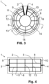
- the Figure 4 shows the case of a rectangular plate 2 which can be heated by PTC thermistors 5 to 8.
- Each PTC thermistor 5 to 8 is of the same nature and runs in a straight line parallel to an edge of the plate 2.
- the PTC thermistors 5 to 8 are spaced equally apart from one another.
- There are three bridges 11, 12 and 13 which electrically connect the PTC thermistors 5 to 8 to one another.
- the bridges 11, 12 and 13 are spaced equally apart from one another.
- the distances between an electrical connecting conductor 9, 10 and the respective adjacent bridge 11 or 13 are also as in the Figure 4 shown accordingly equal.
- Such a plate 2 can, for example, be a side wall of an oven, via which the interior of the oven can be heated.
- the Figure 5 shows an inventive electric heating device for a food preparation device with a large number of electrical PTC thermistors 101 to 108, which are intended for heating a food.
- electrically parallel-connected PTC thermistors which are set up for heating and are therefore intended for heating. If, for example, an electric current flows through a bridge 118 to an electrical PTC thermistor 108, the current is divided into two partial currents. One partial current flows through section 108a and one partial current flows through section 108b of the electrical PTC thermistor 108. Via bridges 113, then the partial currents to the sections 107a and 107b of an adjacently arranged electrical PTC thermistor 107.
- the four sections 107a, 107b, 108a, 108b are counted as three PTC thermistors connected in parallel, which are intended for heating.
- the two PTC thermistor sections 108a, 107a are counted as one PTC thermistor connected in parallel, because the partial current that flows through the PTC thermistor section 108a always necessarily matches the partial current that flows through the PTC thermistor section 107a.
- the two PTC thermistor sections 107b and 108b are counted as two PTC thermistors connected in parallel, because the partial current that flows through the PTC thermistor section 107b does not necessarily match the partial current that flows through the PTC thermistor section 108b.
- a PTC thermistor section is a section of a PTC thermistor between two bridges 113, 118, 119.
- a PTC thermistor 108 intended for heating can be used in the embodiment of the Figure 5 therefore comprise up to four PTC thermistor sections 108a to 108d. A different partial current can flow through each of the PTC thermistor sections 108a to 108d.
- the heating device shown comprises more than fifty electrically parallel connected PTC thermistors for heating a food.
- the cake-piece-like area with the PTC thermistor sections 108a to 108d and the sections 107a and 107b comprises 24 electrically parallel connected PTC thermistors. Opposite this cake-piece-like area is a cake-piece-like area of the same size in the left half of the picture at the same height. This also comprises 24 electrically parallel connected PTC thermistors.
- Two electrical PTC thermistors 101 to 108 intended for heating a food are electrically connected to one another by electrical bridges 113. These electrical bridges 113 are spaced equally apart from one another. Each electrical bridge 113 connects no more than two electrical PTC thermistors 101 to 108 to one another. Each electrical bridge 113 therefore connects exactly two electrical PTC thermistors 101 to 108, which are intended for heating a food.
- the electrical PTC thermistors intended for heating food consist, for example, of an alloy that includes silver in order to be able to cope well with the prevailing environmental influences.
- the alloy can include silver and palladium or consist of silver and palladium.
- An alloy consisting of silver and ruthenium or an alloy that includes silver and ruthenium is particularly preferred.
- the electrical PTC thermistors 101 to 108 intended for heating a food run along circular paths.
- the further electrical PTC thermistors 102 to 107 intended for heating a food run along circular paths.
- PTC thermistors running from the inside to the outside, electrically connected in parallel, intended for heating, which run in a meandering shape from the inside to the outside together with bridges 113 are advantageous in order to be able to measure temperatures appropriately.
- the electrical contacts 116 and 117 are connected by a Figure 5
- Bimetal switches (not shown) are electrically connected to one another.
- the bimetal switch is located above the two electrically parallel connected PTC thermistors which run in a meandering shape from the inside to the outside in conjunction with bridges 113.
- Both electrically parallel connected PTC thermistors which run in a meandering shape from the inside to the outside in conjunction with bridges 113 can therefore heat the bimetal switch independently of one another in such a way that it interrupts the power supply when a temperature threshold is exceeded.
- the width and thus the cross section of the electrical PTC thermistors 101 to 108 intended for heating a food increases with decreasing radius of the respective circular path.
- the electrical PTC thermistors 101 to 108 intended for heating are surrounded by an electrical conductor 109 on the outside.
- the path of the electrical conductor 109 is closed. However, it is not necessary for the path of the electrical conductor 109 to be closed.
- Bridges 119 connect the externally circulating electrical conductor 109 with the electrical PTC thermistors 101 intended for heating. Bridges 119 have the same distances between them. In the case of the Figure 5 all bridges 119 are spaced equally apart from one another.
- the electrical PTC thermistors 101 to 108 intended for heating a food are supplied with power via the electrical conductor 109.
- the electrical PTC thermistors 101 to 108 intended for heating are surrounded by an electrical conductor 111 on the inside.
- Bridges 118 electrically connect the electrical conductor 111 running around the inside to the electrical PTC thermistors 108 intended for heating.
- the electrical bridges 113, 118, 119 and the electrical conductors 109, 110 and 111 used for the power supply consist of a very good electrically conductive material such as silver, copper or gold.
- the two electrical contacts 114 and 115 are provided for connecting a power source.
- the two electrical contacts 114 and 115 are arranged next to each other so that a power source can be connected without any problems. From the electrical contact 114, current can flow along the electrical conductor 110 to the electrical contact 116. From the electrical contact 116, the current passes through the bimetal switch mentioned to the electrical contact 117 and from there to the externally encircling electrical conductor 109.
- the electrical conductor 110 also runs along a circular path so that a circular space remains in the middle that is free of electrical conductors.
- the free space is thus surrounded in a circle by the electrical conductors 110 and 111.
- This free space can be used, for example, to guide a shaft for a stirring tool of the food preparation device through.
- the bridges 118 are spaced equally apart from one another at least when they connect the inner circumferential electrical conductor 111 to one and the same electrical PTC thermistor 108.
- this rule can be deviated from in order to take into account geometric peculiarities that may occur due to the electrical connections 114, 115, due to the bimetal switch between the two electrical connections 116, 117 or due to a temperature sensor 120.
- the temperature sensor 120 is arranged in such a way that it can measure the temperature of two different PTC thermistors that are electrically connected in parallel and intended for heating.
- the two PTC thermistors that are electrically connected in parallel run together with bridges 113 in a meandering shape from the inner circumferential electrical conductor 111 to the outer circumferential electrical conductor 109.
- the Figure 6 illustrates the arrangement of a bimetallic switch 121, which connects the electrical contact 116 with the electrical contact 117.
- This bimetallic switch 121 is located above a cake-shaped area with two electrically parallel-connected PTC thermistors, which are intended for heating and which run in a meandering manner together with bridges 113.
- FIG. 6 also shows a section through a shaft 122 which is guided through the electrical conductors for driving a stirring tool, namely through the free space provided for this purpose.
- the Figure 7 shows two PTC thermistors 101 and 102 intended for heating, which correspond to the PTC thermistors 101 and 102 intended for heating from the Figure 6
- the two PTC thermistors 101 and 102 intended for heating are electrically connected to one another by a bridge 113.
- the material of which the bridge 7 is made overlaps with the material of which the two PTC thermistors 101 and 102 intended for heating are made. In the overlapping area, the bridge 113 is therefore located on the respective PTC thermistor 101, 102. This ensures a particularly reliable and permanent electrical contact between the bridge 113 and the PTC thermistor 101 or PTC thermistor 102.
- the Figure 8 shows an excerpt from Figure 5 with added dashed lines A.
- the lines A divide the heating surface like a piece of cake. This piece of cake-like However, the division is different from that in the Figure 5 called division into pie-shaped areas.
- the lines A run between parallel-connected PTC thermistors 101 to 108, which are intended for heating.
- the total electrical resistance of the PTC thermistors 101 to 108 intended for heating between two dashed lines A is always the same or at least essentially the same.
- the term total resistance means that the electrical resistances of the PTC thermistors 101 to 108 intended for heating are added together within a pie-shaped division. This means that essentially the same heat can be generated within a pie-shaped division between two dashed lines A.
- a sufficiently uniform heating of the area to be heated is thus achieved. Since the electrical resistances of the bridges 113 are much smaller than the electrical resistances of the PTC thermistors 101 to 108 intended for heating, it is not necessary to ensure that the electrical resistances of the bridges 113 are as equal as possible in order to achieve the most uniform heating possible. However, it is advantageous to do so nonetheless.
- section 108a has the same electrical resistance as section 108b.
- Section 107a has the same electrical resistance as section 107b.
- the electrical resistance of sections 107a and 107b is greater than the electrical resistance of sections 108a and 108b because sections 108a and 108b are intended to cover a smaller area to be heated than sections 107a and 107b.
Landscapes
- Engineering & Computer Science (AREA)
- Chemical & Material Sciences (AREA)
- Ceramic Engineering (AREA)
- Food Science & Technology (AREA)
- Resistance Heating (AREA)
- Measuring Temperature Or Quantity Of Heat (AREA)
- Control Of Resistance Heating (AREA)
Claims (13)
- Appareil de préparation d'aliments (1) avec un dispositif de chauffage électrique, qui comprend au moins deux conducteurs électriques à froid (5 à 8 ; 101 à 108) pour un chauffage d'un aliment dans un espace de préparation d'aliments, dans lequel les conducteurs électriques à froid (5 à 8 ; 101 à 108) sont montés électriquement en parallèle,dans lequel deux conducteurs électriques à froid (5 à 8 ; 101 à 108) prévus pour un chauffage d'un aliment sont reliés électriquement entre eux par un ou plusieurs ponts électriques (11 à 17 ; 113),caractérisé en ce que chacun des un ou plusieurs ponts électriques (113) ne relie pas électriquement plus de deux conducteurs électriques à froid (101 à 108).
- Appareil de préparation d'aliments (1) selon la revendication précédente, caractérisé en ce que les conducteurs électriques à froid (5 à 8 ; 101 à 108) prévus pour un chauffage d'un aliment sont constitués d'un alliage de conducteurs chauffants ayant une résistivité électrique d'au moins 0,3 Ω·mm2/m, de préférence d'au moins 1 Ω·mm2/m.
- Appareil de préparation d'aliments (1) selon l'une des revendications précédentes, caractérisé en ce que les conducteurs électriques à froid (101 à 108) prévus pour un chauffage d'un aliment s'étendent le long de trajectoires circulaires.
- Appareil de préparation d'aliments (1) selon la revendication précédente, caractérisé en ce que la section transversale des conducteurs électriques à froid (101 à 108) prévus pour un chauffage d'un aliment augmente lorsque le rayon d'une trajectoire circulaire diminue.
- Appareil de préparation d'aliments (1) selon l'une des revendications précédentes, caractérisé en ce que les conducteurs électriques à froid (101 à 108) prévus pour un chauffage sont circulés extérieurement par un conducteur électrique (109) qui est constitué d'un matériau ayant une résistivité électrique qui est au moins 10 fois, de préférence au moins 100 fois, plus petite que la résistivité électrique du matériau dont sont constitués les conducteurs électriques à froid (101 à 108) prévus pour un chauffage, et des ponts (119) sont prévus, qui relient électriquement le conducteur électrique (109) circulant à l'extérieur aux conducteurs électriques à froid (101) prévus pour un chauffage et/ou que
les conducteurs électriques à froid (101 à 108) prévus pour un chauffage sont circulés intérieurement par un conducteur électrique (111) qui est constitué d'un matériau ayant une résistivité électrique qui est au moins 10 fois, de préférence au moins 100 fois, plus petite que la résistivité électrique du matériau dont sont constitués les conducteurs électriques à froid (101 à 108) prévus pour un chauffage, et des ponts (118) sont prévus qui relient électriquement le conducteur électrique (111) circulant intérieurement à des conducteurs électriques à froid (108) prévus pour un chauffage. - Appareil de préparation d'aliments (1) selon l'une des revendications dépendantes précédentes, caractérisé en ce que les ponts électriques (11 à 17 ; 113) sont constitués d'un matériau ayant une résistivité électrique qui est au moins 10 fois, de préférence au moins 100 fois, plus petite que la résistivité électrique dont sont constitués les conducteurs à froid (5 à 8 ; 101 à 108) prévus pour un chauffage d'un aliment.
- Appareil de préparation d'aliments (1) selon l'une des revendications dépendantes précédentes, caractérisé en ce que les ponts et/ou les conducteurs électriques (109, 110, 111) non prévus pour un chauffage sont constitués d'argent.
- Appareil de préparation d'aliments selon l'une des revendications dépendantes précédentes, caractérisé en ce que des ponts (113, 118, 119) qui sont reliés à un conducteur électrique à froid (101 à 108) présentent des distances égales entre eux.
- Appareil de préparation d'aliments selon l'une des revendications précédentes, caractérisé en ce que le récipient de préparation d'aliments comprend au moins quarante, de préférence au moins cinquante, conducteurs électriques à froid (101 à 108) montés électriquement en parallèle pour un chauffage d'un aliment.
- Appareil de préparation d'aliments selon l'une des revendications précédentes, caractérisé en ce qu'il est prévu un commutateur dépendant de la température, en particulier un commutateur bimétallique (121), qui, en cas de dépassement d'une valeur seuil de température, interrompt une alimentation en courant vers les conducteurs électriques à froid prévus pour un chauffage, dans lequel
le commutateur dépendant de la température (121) est disposé de telle sorte qu'il peut être commuté par la température de deux conducteurs électriques à froid (101 à 108) différents, montés électriquement en parallèle et prévus pour un chauffage. - Appareil de préparation d'aliments selon l'une des revendications précédentes, caractérisé en ce qu'un capteur de température (120) de l'appareil de préparation d'aliments est disposé de telle sorte que le capteur de température (120) peut être chauffé par deux conducteurs électriques à froid (101 à 108) différents montés électriquement en parallèle et prévus pour un chauffage.
- Appareil de préparation d'aliments selon l'une des revendications précédentes, caractérisé en ce que les conducteurs électriques à froid (101 à 108) prévus pour un chauffage s'étendent, ensemble avec des ponts (113), en forme de méandres.
- Appareil de préparation d'aliments selon la revendication précédente, caractérisé en ce que deux conducteurs électriques à froid (101 à 108) prévus pour un chauffage s'étendent, ensemble avec des ponts (113), en forme de méandres qui sont montés électriquement en parallèle.
Priority Applications (3)
| Application Number | Priority Date | Filing Date | Title |
|---|---|---|---|
| AU2021204025A AU2021204025B2 (en) | 2019-07-11 | 2021-06-17 | Food preparation device with parallel electrical cold conductors |
| CN202110765075.9A CN114081358B (zh) | 2019-07-11 | 2021-07-06 | 具有并联电冷导体的食物制备装置 |
| US17/369,402 US11997765B2 (en) | 2019-07-11 | 2021-07-07 | Food preparation device with parallel electrical cold conductors |
Applications Claiming Priority (1)
| Application Number | Priority Date | Filing Date | Title |
|---|---|---|---|
| EP19185781.2A EP3764738B1 (fr) | 2019-07-11 | 2019-07-11 | Appareil de préparation d'aliments pourvu de conducteurs électriques ptc à commutation parallèle |
Publications (3)
| Publication Number | Publication Date |
|---|---|
| EP3764739A1 EP3764739A1 (fr) | 2021-01-13 |
| EP3764739B1 true EP3764739B1 (fr) | 2024-08-28 |
| EP3764739C0 EP3764739C0 (fr) | 2024-08-28 |
Family
ID=67253779
Family Applications (2)
| Application Number | Title | Priority Date | Filing Date |
|---|---|---|---|
| EP19185781.2A Active EP3764738B1 (fr) | 2019-07-11 | 2019-07-11 | Appareil de préparation d'aliments pourvu de conducteurs électriques ptc à commutation parallèle |
| EP20184513.8A Active EP3764739B1 (fr) | 2019-07-11 | 2020-07-07 | Dispositif de préparation des aliments pourvu de résistances à coefficient de température positive électriques montées en parallèle |
Family Applications Before (1)
| Application Number | Title | Priority Date | Filing Date |
|---|---|---|---|
| EP19185781.2A Active EP3764738B1 (fr) | 2019-07-11 | 2019-07-11 | Appareil de préparation d'aliments pourvu de conducteurs électriques ptc à commutation parallèle |
Country Status (6)
| Country | Link |
|---|---|
| US (2) | US11638330B2 (fr) |
| EP (2) | EP3764738B1 (fr) |
| CN (2) | CN112218395B (fr) |
| AU (2) | AU2020204586B2 (fr) |
| ES (2) | ES2975431T3 (fr) |
| PL (2) | PL3764738T3 (fr) |
Families Citing this family (3)
| Publication number | Priority date | Publication date | Assignee | Title |
|---|---|---|---|---|
| ES2975431T3 (es) * | 2019-07-11 | 2024-07-05 | Vorwerk Co Interholding | Aparato de preparación de alimentos con termistores eléctricos PTC conectados en paralelo |
| DE102019214435A1 (de) * | 2019-09-23 | 2021-03-25 | Robert Bosch Gmbh | Heizeinrichtung |
| EP4248809A1 (fr) | 2022-03-22 | 2023-09-27 | Vorwerk & Co. Interholding GmbH | Appareil de préparation des aliments pourvu de dispositif de protection contre la surchauffe |
Family Cites Families (20)
| Publication number | Priority date | Publication date | Assignee | Title |
|---|---|---|---|---|
| US5274216A (en) * | 1989-08-15 | 1993-12-28 | Aladdin Synergetics, Inc. | Food rethermalizing and satelliting tray |
| WO1991002481A1 (fr) * | 1989-08-15 | 1991-03-07 | Aladdin Synergetics, Inc. | Systeme de chariot pour aliments et methode pour leur rechauffage |
| GB8924936D0 (en) * | 1989-11-04 | 1989-12-28 | Ceramaspeed Ltd | Radiant electric heaters |
| CN2083010U (zh) * | 1990-04-16 | 1991-08-21 | 北京市太阳能研究所 | 电热多用锅 |
| GB2296847B (en) * | 1994-11-30 | 1999-03-24 | Strix Ltd | Electric heaters |
| GB9622695D0 (en) * | 1996-10-31 | 1997-01-08 | Delta Theta Ltd | Thermal elements |
| EP0853444B1 (fr) * | 1997-01-10 | 2005-11-23 | E.G.O. ELEKTRO-GERÄTEBAU GmbH | Système à cuire avec une plaque de cuisson électrique, transférant la chaleur par conduction |
| DE10019126A1 (de) | 2000-04-18 | 2001-10-25 | Vorwerk Co Interholding | Küchenmaschine mit einem Rührgefäß |
| DE202004007542U1 (de) | 2004-05-07 | 2004-09-02 | Zwilling J. A. Henckels Ag | Kochgeschirr, insbesondere Topf, Pfanne o.dgl. |
| US10920379B2 (en) * | 2005-02-17 | 2021-02-16 | Greenheat Ip Holdings Llc | Grounded modular heated cover |
| JP2007143804A (ja) * | 2005-11-28 | 2007-06-14 | Masayuki Takashima | 飲食物加熱装置 |
| US8269150B2 (en) * | 2007-07-20 | 2012-09-18 | Lg Electronics Inc. | Electric heater |
| EP2307807A2 (fr) * | 2008-05-01 | 2011-04-13 | Thermoceramix, Inc. | Appareils de cuisson utilisant des revêtements de résistance |
| DE102008038783B4 (de) * | 2008-08-12 | 2017-11-09 | Vorwerk & Co. Interholding Gmbh | Küchenmaschine mit einem Rührgefäß sowie Verfahren hierzu |
| US8901463B2 (en) * | 2011-09-16 | 2014-12-02 | General Electric Company | Thermal management device |
| EP3015360B1 (fr) * | 2014-10-29 | 2019-05-29 | Airbus Operations GmbH | Panneau de plancher pour un aéronef et aéronef comprenant un tel panneau |
| DE102016121306B3 (de) * | 2016-11-08 | 2017-11-30 | Miele & Cie. Kg | Haushaltgerät und Elektrisches Heizelement zur Verwendung in einem Haushaltgerät |
| DE102016224069A1 (de) * | 2016-12-02 | 2018-06-07 | E.G.O. Elektro-Gerätebau GmbH | Kochgerät mit einer Kochplatte und einer Heizeinrichtung darunter |
| CN108652438A (zh) * | 2017-03-31 | 2018-10-16 | 佛山市顺德区美的电热电器制造有限公司 | 电水壶及其加热控制系统 |
| ES2975431T3 (es) * | 2019-07-11 | 2024-07-05 | Vorwerk Co Interholding | Aparato de preparación de alimentos con termistores eléctricos PTC conectados en paralelo |
-
2019
- 2019-07-11 ES ES19185781T patent/ES2975431T3/es active Active
- 2019-07-11 PL PL19185781.2T patent/PL3764738T3/pl unknown
- 2019-07-11 EP EP19185781.2A patent/EP3764738B1/fr active Active
-
2020
- 2020-07-07 ES ES20184513T patent/ES2988172T3/es active Active
- 2020-07-07 EP EP20184513.8A patent/EP3764739B1/fr active Active
- 2020-07-07 PL PL20184513.8T patent/PL3764739T3/pl unknown
- 2020-07-09 AU AU2020204586A patent/AU2020204586B2/en active Active
- 2020-07-09 CN CN202010658493.3A patent/CN112218395B/zh active Active
- 2020-07-09 US US16/925,321 patent/US11638330B2/en active Active
-
2021
- 2021-06-17 AU AU2021204025A patent/AU2021204025B2/en active Active
- 2021-07-06 CN CN202110765075.9A patent/CN114081358B/zh active Active
- 2021-07-07 US US17/369,402 patent/US11997765B2/en active Active
Also Published As
| Publication number | Publication date |
|---|---|
| EP3764738C0 (fr) | 2024-02-07 |
| AU2020204586A1 (en) | 2021-01-28 |
| EP3764739A1 (fr) | 2021-01-13 |
| ES2975431T3 (es) | 2024-07-05 |
| CN114081358A (zh) | 2022-02-25 |
| AU2020204586B2 (en) | 2024-07-11 |
| AU2021204025A1 (en) | 2022-01-27 |
| PL3764738T3 (pl) | 2024-06-17 |
| US11997765B2 (en) | 2024-05-28 |
| US20210144814A1 (en) | 2021-05-13 |
| ES2988172T3 (es) | 2024-11-19 |
| PL3764739T3 (pl) | 2024-12-16 |
| EP3764738B1 (fr) | 2024-02-07 |
| CN112218395B (zh) | 2023-01-24 |
| EP3764738A1 (fr) | 2021-01-13 |
| US11638330B2 (en) | 2023-04-25 |
| EP3764739C0 (fr) | 2024-08-28 |
| US20220015197A1 (en) | 2022-01-13 |
| CN114081358B (zh) | 2024-10-22 |
| CN112218395A (zh) | 2021-01-12 |
| AU2021204025B2 (en) | 2023-05-04 |
Similar Documents
| Publication | Publication Date | Title |
|---|---|---|
| EP0103741B1 (fr) | Elément chauffant, en particulier élément chauffant radiant pour le chauffage de plaques en céramique | |
| EP3764739B1 (fr) | Dispositif de préparation des aliments pourvu de résistances à coefficient de température positive électriques montées en parallèle | |
| EP0531987B2 (fr) | Dispositif de chauffage électrique | |
| EP2844029B1 (fr) | Dispositif de chauffage et son procédé de fonctionnement | |
| EP3331319B1 (fr) | Appareil de cuisson doté d'une plaque de cuisson et d'un dispositif de chauffage correspondant | |
| DE2205132C3 (de) | Elektrokochgerät | |
| DE2518949A1 (de) | Glaskeramik-kochfeld mit filmheizelement | |
| DE3622415A1 (de) | Strahlheizkoerper | |
| DE102011057149A1 (de) | Mehrzweck-Induktionskochfeld | |
| CH658761A5 (de) | Elektrische heizvorrichtung fuer kochherde mit einer kochplatte aus glaskeramik. | |
| DE69317063T2 (de) | Heizapparat und Fühler für eine Herdplatte | |
| DE3613902A1 (de) | Kochplatte, insbesondere fuer grosskuechen-herde | |
| EP0035254B1 (fr) | Dispositif électrique chauffant pour cuisinières ou plaques chauffantes | |
| EP3598848B2 (fr) | Table de cuisson | |
| EP1448024A2 (fr) | Equipement du chauffage avec deux domaines | |
| DE3314501A1 (de) | Heizelement, insbesondere strahlungs-heizelement fuer die beheizung von glaskeramikplatten | |
| CH639807A5 (de) | Kombinierter herd fuer mikrowellen- und widerstandsheizung. | |
| EP2943044B1 (fr) | Élément thermique d'appareil de cuisson et appareil de cuisson, en particulier table de cuisson | |
| DE3206024A1 (de) | Elektrokochplatte, vorzugsweise glaskeramik-kochmulde | |
| EP2983449B1 (fr) | Procede d'acceleration d'un processus de cuisson, dispositif de commande et appareil de cuisson correspondant | |
| EP1774554B1 (fr) | Dispositif pour commander plusieurs unites de chauffage d'un appareil de cuisson, et appareil de cuisson equipe d'un tel dispositif | |
| WO2015062859A1 (fr) | Dispositif de cuisson équipé d'une plaque de chauffage | |
| EP3771287A1 (fr) | Dispositif chauffant à rayonnement et plaque de cuisson dotée d'un tel dispositif chauffant à rayonnement | |
| EP3210508B1 (fr) | Gril électrique | |
| DE3735265C2 (fr) |
Legal Events
| Date | Code | Title | Description |
|---|---|---|---|
| PUAI | Public reference made under article 153(3) epc to a published international application that has entered the european phase |
Free format text: ORIGINAL CODE: 0009012 |
|
| STAA | Information on the status of an ep patent application or granted ep patent |
Free format text: STATUS: THE APPLICATION HAS BEEN PUBLISHED |
|
| AK | Designated contracting states |
Kind code of ref document: A1 Designated state(s): AL AT BE BG CH CY CZ DE DK EE ES FI FR GB GR HR HU IE IS IT LI LT LU LV MC MK MT NL NO PL PT RO RS SE SI SK SM TR |
|
| AX | Request for extension of the european patent |
Extension state: BA ME |
|
| STAA | Information on the status of an ep patent application or granted ep patent |
Free format text: STATUS: REQUEST FOR EXAMINATION WAS MADE |
|
| 17P | Request for examination filed |
Effective date: 20210421 |
|
| RBV | Designated contracting states (corrected) |
Designated state(s): AL AT BE BG CH CY CZ DE DK EE ES FI FR GB GR HR HU IE IS IT LI LT LU LV MC MK MT NL NO PL PT RO RS SE SI SK SM TR |
|
| REG | Reference to a national code |
Ref legal event code: R079 Free format text: PREVIOUS MAIN CLASS: H05B0003680000 Ipc: H05B0003740000 Ref country code: DE Ref legal event code: R079 Ref document number: 502020009002 Country of ref document: DE Free format text: PREVIOUS MAIN CLASS: H05B0003680000 Ipc: H05B0003740000 |
|
| GRAP | Despatch of communication of intention to grant a patent |
Free format text: ORIGINAL CODE: EPIDOSNIGR1 |
|
| STAA | Information on the status of an ep patent application or granted ep patent |
Free format text: STATUS: GRANT OF PATENT IS INTENDED |
|
| RIC1 | Information provided on ipc code assigned before grant |
Ipc: A47J 43/07 20060101ALN20240318BHEP Ipc: H05B 3/74 20060101AFI20240318BHEP |
|
| INTG | Intention to grant announced |
Effective date: 20240423 |
|
| GRAS | Grant fee paid |
Free format text: ORIGINAL CODE: EPIDOSNIGR3 |
|
| GRAA | (expected) grant |
Free format text: ORIGINAL CODE: 0009210 |
|
| STAA | Information on the status of an ep patent application or granted ep patent |
Free format text: STATUS: THE PATENT HAS BEEN GRANTED |
|
| AK | Designated contracting states |
Kind code of ref document: B1 Designated state(s): AL AT BE BG CH CY CZ DE DK EE ES FI FR GB GR HR HU IE IS IT LI LT LU LV MC MK MT NL NO PL PT RO RS SE SI SK SM TR |
|
| REG | Reference to a national code |
Ref country code: CH Ref legal event code: EP |
|
| REG | Reference to a national code |
Ref country code: DE Ref legal event code: R096 Ref document number: 502020009002 Country of ref document: DE |
|
| REG | Reference to a national code |
Ref country code: IE Ref legal event code: FG4D Free format text: LANGUAGE OF EP DOCUMENT: GERMAN |
|
| U01 | Request for unitary effect filed |
Effective date: 20240828 |
|
| U07 | Unitary effect registered |
Designated state(s): AT BE BG DE DK EE FI FR IT LT LU LV MT NL PT RO SE SI Effective date: 20240904 |
|
| REG | Reference to a national code |
Ref country code: ES Ref legal event code: FG2A Ref document number: 2988172 Country of ref document: ES Kind code of ref document: T3 Effective date: 20241119 |
|
| PG25 | Lapsed in a contracting state [announced via postgrant information from national office to epo] |
Ref country code: NO Free format text: LAPSE BECAUSE OF FAILURE TO SUBMIT A TRANSLATION OF THE DESCRIPTION OR TO PAY THE FEE WITHIN THE PRESCRIBED TIME-LIMIT Effective date: 20241128 |
|
| PG25 | Lapsed in a contracting state [announced via postgrant information from national office to epo] |
Ref country code: GR Free format text: LAPSE BECAUSE OF FAILURE TO SUBMIT A TRANSLATION OF THE DESCRIPTION OR TO PAY THE FEE WITHIN THE PRESCRIBED TIME-LIMIT Effective date: 20241129 |
|
| PG25 | Lapsed in a contracting state [announced via postgrant information from national office to epo] |
Ref country code: IS Free format text: LAPSE BECAUSE OF FAILURE TO SUBMIT A TRANSLATION OF THE DESCRIPTION OR TO PAY THE FEE WITHIN THE PRESCRIBED TIME-LIMIT Effective date: 20241228 |
|
| PG25 | Lapsed in a contracting state [announced via postgrant information from national office to epo] |
Ref country code: HR Free format text: LAPSE BECAUSE OF FAILURE TO SUBMIT A TRANSLATION OF THE DESCRIPTION OR TO PAY THE FEE WITHIN THE PRESCRIBED TIME-LIMIT Effective date: 20240828 |
|
| PG25 | Lapsed in a contracting state [announced via postgrant information from national office to epo] |
Ref country code: RS Free format text: LAPSE BECAUSE OF FAILURE TO SUBMIT A TRANSLATION OF THE DESCRIPTION OR TO PAY THE FEE WITHIN THE PRESCRIBED TIME-LIMIT Effective date: 20241128 |
|
| PG25 | Lapsed in a contracting state [announced via postgrant information from national office to epo] |
Ref country code: RS Free format text: LAPSE BECAUSE OF FAILURE TO SUBMIT A TRANSLATION OF THE DESCRIPTION OR TO PAY THE FEE WITHIN THE PRESCRIBED TIME-LIMIT Effective date: 20241128 Ref country code: NO Free format text: LAPSE BECAUSE OF FAILURE TO SUBMIT A TRANSLATION OF THE DESCRIPTION OR TO PAY THE FEE WITHIN THE PRESCRIBED TIME-LIMIT Effective date: 20241128 Ref country code: IS Free format text: LAPSE BECAUSE OF FAILURE TO SUBMIT A TRANSLATION OF THE DESCRIPTION OR TO PAY THE FEE WITHIN THE PRESCRIBED TIME-LIMIT Effective date: 20241228 Ref country code: HR Free format text: LAPSE BECAUSE OF FAILURE TO SUBMIT A TRANSLATION OF THE DESCRIPTION OR TO PAY THE FEE WITHIN THE PRESCRIBED TIME-LIMIT Effective date: 20240828 Ref country code: GR Free format text: LAPSE BECAUSE OF FAILURE TO SUBMIT A TRANSLATION OF THE DESCRIPTION OR TO PAY THE FEE WITHIN THE PRESCRIBED TIME-LIMIT Effective date: 20241129 |
|
| PG25 | Lapsed in a contracting state [announced via postgrant information from national office to epo] |
Ref country code: SM Free format text: LAPSE BECAUSE OF FAILURE TO SUBMIT A TRANSLATION OF THE DESCRIPTION OR TO PAY THE FEE WITHIN THE PRESCRIBED TIME-LIMIT Effective date: 20240828 |
|
| PG25 | Lapsed in a contracting state [announced via postgrant information from national office to epo] |
Ref country code: CZ Free format text: LAPSE BECAUSE OF FAILURE TO SUBMIT A TRANSLATION OF THE DESCRIPTION OR TO PAY THE FEE WITHIN THE PRESCRIBED TIME-LIMIT Effective date: 20240828 |
|
| PG25 | Lapsed in a contracting state [announced via postgrant information from national office to epo] |
Ref country code: SK Free format text: LAPSE BECAUSE OF FAILURE TO SUBMIT A TRANSLATION OF THE DESCRIPTION OR TO PAY THE FEE WITHIN THE PRESCRIBED TIME-LIMIT Effective date: 20240828 |
|
| PLBE | No opposition filed within time limit |
Free format text: ORIGINAL CODE: 0009261 |
|
| STAA | Information on the status of an ep patent application or granted ep patent |
Free format text: STATUS: NO OPPOSITION FILED WITHIN TIME LIMIT |
|
| PGFP | Annual fee paid to national office [announced via postgrant information from national office to epo] |
Ref country code: PL Payment date: 20250627 Year of fee payment: 6 |
|
| 26N | No opposition filed |
Effective date: 20250530 |
|
| U20 | Renewal fee for the european patent with unitary effect paid |
Year of fee payment: 6 Effective date: 20250729 |
|
| PGFP | Annual fee paid to national office [announced via postgrant information from national office to epo] |
Ref country code: ES Payment date: 20250819 Year of fee payment: 6 |
|
| PGFP | Annual fee paid to national office [announced via postgrant information from national office to epo] |
Ref country code: GB Payment date: 20250724 Year of fee payment: 6 |
|
| PGFP | Annual fee paid to national office [announced via postgrant information from national office to epo] |
Ref country code: CH Payment date: 20250724 Year of fee payment: 6 |