EP0531987B2 - Dispositif de chauffage électrique - Google Patents
Dispositif de chauffage électrique Download PDFInfo
- Publication number
- EP0531987B2 EP0531987B2 EP92115467A EP92115467A EP0531987B2 EP 0531987 B2 EP0531987 B2 EP 0531987B2 EP 92115467 A EP92115467 A EP 92115467A EP 92115467 A EP92115467 A EP 92115467A EP 0531987 B2 EP0531987 B2 EP 0531987B2
- Authority
- EP
- European Patent Office
- Prior art keywords
- temperature
- heaters
- switching
- heating unit
- heater
- Prior art date
- Legal status (The legal status is an assumption and is not a legal conclusion. Google has not performed a legal analysis and makes no representation as to the accuracy of the status listed.)
- Expired - Lifetime
Links
Images

Classifications
-
- F—MECHANICAL ENGINEERING; LIGHTING; HEATING; WEAPONS; BLASTING
- F24—HEATING; RANGES; VENTILATING
- F24C—DOMESTIC STOVES OR RANGES ; DETAILS OF DOMESTIC STOVES OR RANGES, OF GENERAL APPLICATION
- F24C15/00—Details
- F24C15/10—Tops, e.g. hot plates; Rings
- F24C15/102—Tops, e.g. hot plates; Rings electrically heated
- F24C15/106—Tops, e.g. hot plates; Rings electrically heated electric circuits
-
- G—PHYSICS
- G05—CONTROLLING; REGULATING
- G05D—SYSTEMS FOR CONTROLLING OR REGULATING NON-ELECTRIC VARIABLES
- G05D23/00—Control of temperature
- G05D23/19—Control of temperature characterised by the use of electric means
- G05D23/1927—Control of temperature characterised by the use of electric means using a plurality of sensors
- G05D23/193—Control of temperature characterised by the use of electric means using a plurality of sensors sensing the temperaure in different places in thermal relationship with one or more spaces
- G05D23/1932—Control of temperature characterised by the use of electric means using a plurality of sensors sensing the temperaure in different places in thermal relationship with one or more spaces to control the temperature of a plurality of spaces
- G05D23/1934—Control of temperature characterised by the use of electric means using a plurality of sensors sensing the temperaure in different places in thermal relationship with one or more spaces to control the temperature of a plurality of spaces each space being provided with one sensor acting on one or more control means
-
- H—ELECTRICITY
- H05—ELECTRIC TECHNIQUES NOT OTHERWISE PROVIDED FOR
- H05B—ELECTRIC HEATING; ELECTRIC LIGHT SOURCES NOT OTHERWISE PROVIDED FOR; CIRCUIT ARRANGEMENTS FOR ELECTRIC LIGHT SOURCES, IN GENERAL
- H05B3/00—Ohmic-resistance heating
- H05B3/68—Heating arrangements specially adapted for cooking plates or analogous hot-plates
-
- Y—GENERAL TAGGING OF NEW TECHNOLOGICAL DEVELOPMENTS; GENERAL TAGGING OF CROSS-SECTIONAL TECHNOLOGIES SPANNING OVER SEVERAL SECTIONS OF THE IPC; TECHNICAL SUBJECTS COVERED BY FORMER USPC CROSS-REFERENCE ART COLLECTIONS [XRACs] AND DIGESTS
- Y02—TECHNOLOGIES OR APPLICATIONS FOR MITIGATION OR ADAPTATION AGAINST CLIMATE CHANGE
- Y02B—CLIMATE CHANGE MITIGATION TECHNOLOGIES RELATED TO BUILDINGS, e.g. HOUSING, HOUSE APPLIANCES OR RELATED END-USER APPLICATIONS
- Y02B30/00—Energy efficient heating, ventilation or air conditioning [HVAC]
- Y02B30/70—Efficient control or regulation technologies, e.g. for control of refrigerant flow, motor or heating
Definitions
- the invention relates to an electric heating unit according to the preamble of claim 1. You should especially for a hotplate or other to be heated Areas may be suitable in which heat conduction and / or radiation thermal energy in the area to be given to a heating surface.
- heating units e.g. Electric hotplates
- a temperature control or control of separate heating resistors services added or given be provided.
- a temperature sensor in the annularly heated area, in the unheated center or at least elsewhere directly the radiation a heating resistor and / or a heating respectively.
- a power control device is provided, this switches the specified power periodically on and off, whereby the relative switch-on time with a higher one Temperature increases.
- z. B. is given when heating large amounts of water, can the switching processes of regulation or control to disadvantageous switching impulses and in particular lead to an inadmissible click rate.
- the withdrawal the thermal energy can also be in different areas the heating surface must be different and also switch, which makes a desired different or even temperature distribution undesirably changes across the area without any possibilities given these changes to control.
- this is usually the case Touching the floor in the area of the outer circumference the cooking or heating surface while it is in the center is non-contact, so that the heating surface in this area lack of good heat transfer in the temperature rises sharply.
- GB-A-2 067 857 relates to a heating unit at which switched two heaters in such a way be that when one is operating the other is out of order.
- DE-A 3 810 586 shows a two-circuit heating with temperature sensors, which protect against overheating serve.
- DE-A35 39 581 shows a method for controlling electrical power Electric stove heaters. To reduce network interference the loads are chained together within there switched to the network at one cycle time.
- the invention has for its object a To create heating unit, at which disadvantages are known Avoid training or the type described are and in particular a mutual relative Adjustment of the temperature in separate areas of the heating surface.
- the features according to claim 1 provided. Two or more neighboring, contiguous, merging and / or within a common perimeter areas of the heating surface to be regulated separately. This allows the Temperature or the heating power for each of these surface areas e.g. be adjusted to how much Thermal energy in relation to the respective area to at least one other area is removed. This ratio changes over the course of time, the temperature control can follow. This makes it possible to use both surface areas essentially independent of heat extraction at the same temperature or at a desired one To keep the temperature difference, e.g. time- and / or can be changed depending on the temperature.
- the temperature control is expediently not carried out by changing the thermal coupling of the Areas, but by changing the power supplied to associated heaters, in particular the electrical power supplied. Further is achieved in that the desired temperature difference between the surface areas contrary regulation of both surface areas faster is achieved.
- At least one is determined Benefit amount periodically and alternately to at least switched two surface areas.
- alternating current is the longest period advantageously much shorter than a second or half a second.
- the switchover takes place in Moment of passage of the wavy AC characteristic curve through the middle zero line, so that no interference pulses occur. If the Switching on for one area is practical at the same time as the switch-off process for the other Area, there is no interruption in the power drawn from the power source, so that the switching process has no clicks caused.
- at switching between at least two heaters or heating circuits can e.g. B. the time intervals of Power supply selected for all heaters approximately the same size so that all heaters essentially with an equal percentage of the total heating output of the heating surface. Results from lower Extraction of heat in the heating area of a heater a corresponding rise in temperature, this will be detected by temperature sensing and it is by a automatic or temperature-dependent control the duration of the power supply time intervals this heater decreased while the corresponding one Duration is increased for at least one further heating, until there is a temperature distribution corresponding to an adjustment hired again.
- the readjustment described by relative change the time intervals is especially then useful if large amounts of thermal energy are removed be like z.
- B. is the case when in a large cooking vessel large quantities of food with high Approximate amount of water at room temperature should be heated to cooking temperature.
- pan dishes that are not with the full or highest possible performance of the heating unit, but with an approximately half lower heat output is one possible uniform heating of the pan base and therefore also an increase in temperature in that Area desired in which the heat transfer is worse.
- To work in both modes To be able to, is the mentioned adjustment the time intervals only from a predetermined temperature level provided that higher than 250 ° C and preferably is at 300 ° C, this temperature only by a few degrees, e.g.
- the heating surface or the surface areas is also a Protection against overheating is given, so that a separate Temperature switch or temperature sensor for the Overheating protection is not required.
- It can also described training for pot detection or automatic detection can be used whether the heating surface without proper heat extraction is operated at idle or the intended Heat extraction, e.g. B. by one of the pot standing on the heating surface. For this can the power, the temperature and if necessary the duration of which are electronically compared and it can have a resulting value derived whether the heating unit is idling or not.
- the power distribution can also be used for this purpose or the temperature distribution between at least two surface areas are covered; is this distribution particularly evenly, this corresponds to the fact that no heat is removed and the Control means switching according to pre-programmed or pre-adjusted Duration at least part of the supplied Performance from. As soon as heat is removed takes place, this power is automatically switched on again.
- the switchover is advantageously carried out between surface areas a single heating surface.
- the respective Heating area is essentially one closed scope and an almost complete gap heated ring zone defined, the circumference in the essentially symmetrical to an axial plane or one Central axis of the heating surface is. In the case of a hotplate this heating surface forms at least one along the scope essentially continuously heated base for a single cooking vessel.
- the heating unit 1 can at least partially as Radiant heaters for arrangement on a translucent Stovetop made of glass ceramic or the like, as with such Cooker or stove top structurally combined heating unit, as an electric hotplate with a metallic hotplate body or the like. and is preferred as a low-mass hotplate using thick-film technology formed, the thermal storage capacity and / or conductivity of your material specifically expediently much less than that a metallic material, in particular of Cast steel is.
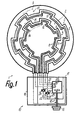
- To form heating areas are only two heaters 3, 4 or heating resistors 5, 6 are provided, each separate from the other heater, self-contained and separately taxable or form an adjustable heating circuit.
- the heaters 3, 4 are used for heating in the area a heating surface 2.
- a radiant heater can be installed on the back of a Glass ceramic plate the heating surface 2 as a substantially level area in which the Heaters 3, 4 are or up to which the heating resistors 5, 6 with their one thermally and / or electrically insulating support facing away from front or Reach the top.
- the heating resistors 5, 6 are z. B. on the top of this pot-shaped insulation support arranged, so with its pot edge on the To attach the back of the hotplate is that the The front of its pot rim is essentially closed or fits tightly with pressure on the hotplate and the heaters 4, 5 are within the rim of the pot.
- At least one Heating resistor on the back of the hotplate as laminated thick film resistance and in the case of a Heating unit in which at least one heating resistor in the form of a resistance coil, a tubular heater or the like. Attached to the back of the hotplate or embedded in an electrically insulated manner is the heating surface 2 than that remote from the heating resistor, essentially flat side of the hotplate or the plate body to understand.
- the heating surface is 2 am Outer circumference limited in the area up to which at least one heater 3 clearly thermal and warming up a short time after being switched on acts, the radial distance of the outer circumference or the outer boundary 9 of the heating surface 2 essential from the outermost area of the heaters 3, 4 is smaller than their radial extent.
- Each heater 3, 4 is a separate temperature sensor 7, 8 assigned, which is expedient approximately in the area the associated heater 3, 4 and / or immediately adjacent to that side of this heater 3, 4 feels that is facing the center of the heating surface 2.
- the temperature sensor can essentially along of the entire associated heating resistor 6 or 7. Furthermore, the temperature sensing can be about in the level of the associated heating 3 or 4 or, z. B. in the case of a radiant heater, close to or at the back of the hotplate, of which the each heater 3 or 4 exposed a clear distance may have.
- control unit 10 for manual and automatic depending on Determination of the heating control 3, 4 is a control unit 10 as the control means provided that conveniently one of the heated Forms a separate assembly and with the heated unit via flexible connecting lines connected is.
- the control unit 10 serves both for manual setting of the desired temperature or heating power of the heated assembly as well automatic execution of control processes due to of temperature values that are temperature dependent variable measuring resistances 11, 12 of the temperature sensors 7, 8 via signal lines to control elements forward the control unit 10.
- the heating resistors 5, 6 are almost closed arranged in a ring and coaxially one inside the other the respective, strip-shaped elongated heating resistor 5 or 6 has one within its ring course meandering course in that in the circumferential direction contiguous circumferential sections different radial distances from the center have the heating surface 2 and about radial intermediate sections merge into one another, the peripheral sections only two clearly different radial distances from the center, are about the same length and have a length that is substantially greater than their width is.
- the respective, compared to the width of the heating resistor much narrower measuring resistor 11 or 12 runs approximately parallel and with little, approximately constant distance adjacent to the associated Longitudinal edge of the heating resistor 5 assigned to it or 6, so that the measuring resistor 11 or 12 a has a meandering course and approximately annular closed is.
- the respective measuring resistor 11 or 12 can also be used as a thick-film sensor, e.g. B. by Imprint directly on the back of the hotplate be laminated.
- the outer circumference of the outer surface area 13 determines the outer boundary 9 of the Heating surface 2 and within the inner circumference of the inner No area 14 is provided, the width of this unheated inner field at least 1/3 as large as the width of the outer circumference 9 is.
- the regulating and control unit 10 has a z. B. housing-shaped base 16 made of electrically insulating Material in which preferably completely sinks or encapsulates all electrically conductive parts except for connections for the connecting lines to the heated Module and connections 17 for power supply or device lines are arranged.
- the Sokkel 16 is e.g. B. on the inside of a control panel of the associated device, such as a cooker attach and has a freely accessible on its outside projecting handle 19 for manual adjustment the desired operating status on.
- the handle 19 suitably sits on an actuating shaft for the actuation of contacts, in particular of Switch contacts 18 with which connecting lines electrically between the terminals 17 and the rest conductive parts open and closed all poles can be.
- a first rotary switching step is used to close the switch contacts 18 and further rotary steps are used for setting the different operating modes.
- the control shaft or the handle 19 acts for this further on an electronic control device 20, as a separate assembly within the Sokkels 16 is arranged.
- the two, from the connectors 17 coming connection lines are after the switch contacts 18 to the associated Connection ends of the heating resistors 5, 6 connected, wherein a connecting line in separate connecting lines 21, 22 for one connection end each the heating resistors 5, 6 is branched.
- every Connection line 21, 22 is an electronic relay 23 or 24 interposed, its functional states from the control unit 10 in each case via a control line 25 or 26 can be controlled.
- connection ends of the measuring resistors 11, 12 are via signal lines 27, 28 separately at inputs of the control device 20 connected, which by the temperature sensors 7, 8 measured absolute temperatures, the Difference and, if applicable, their duration processed and derived control signals from it to the relays 23, 24 passes on.
- the control is provided that the relays 23, 24 either both for the passage of current can be closed or that alternately one relay closed and the other open is when opening or closing one relay at the same time as closing or The other relay opens.
- the control unit 10 can be due to control heating clocked power control device and / or be a temperature controller, which has a or both temperature sensors measure the temperature in the range of Heating surface 2 monitored so that when a set one is reached Temperature supplied to heaters 3, 4 electrical power reduced and after falling below a predetermined lower limit temperature is fed back in full. simultaneously the control device 20 operates in the manner of a Full wave control so that the relays 23, 24 only in switches at the moment when the characteristic curve of the supplied alternating current after termination of one full wave of characteristic in the passage through the zero line is on both sides of which the wave arches of the Characteristic curve.
- the relays 23, 24 are e.g. B. operated so that successive Wave packets from z. B. twenty contiguous Solid waves of the characteristic curve 29 in any different or the same distribution under one-time division for power supply consecutive fed to both heaters 3, 4 become. Of the twenty solid waves in each wave packet can then B. a shaft subpackage 33 with eight continuously contiguous full waves of the heater 4 and then by switching 32 the remaining Shaft part package 34 with twelve full shafts of heating 3 are supplied, after which due to another Switch 32 the next wave subpackage again the heater 4 is supplied, etc.
- the ratio of Number of shafts between the two shaft part packages 33, 34 can remain constant or, for. B. be temperature-dependent, changeable.
- the switchover 32 takes place in each case in the passage 31 of the Characteristic curve 29 through the zero line 30.
- the periodic switching described can in every temperature or set power range the heating unit, i.e. even in the lower or lowest power range can be provided, especially it is appropriate, however, in higher or highest performance range because then a bad one Extraction of heat in a surface area 13 or 14 quickly lead to overheating of this area can.
- at least one performance range e.g. B. in the lower or lowest power range the size of the two partial shaft packets 33, 34 approximately be the same size, while only in the higher or highest Performance range the named differentiation this size ratio is done to z. B. the circumstance Take into account that cooking pots usually better heat transfer in the outer surface area 13 enable than in the inner surface area 14.
- the differentiation of the size ratio can with increasing temperature in the range the heating surface 2 also continuously or step by step increase.
- the periodic switchover makes it practical the electrical from a single supply line via a switch Energy running or only with very short interruptions on at least two heaters 3, 4 of the same Distributed heating field.
- the time intervals of the allocation or interruption are in relation to the thermal inertia in the area of the heating surface 2 so in short that the temperature of the respective area not or only marginally during allocation about the temperature during the interruption the allocation increases, or that the temperature during this interruption not or only very slightly below the temperature during the allocation decreases.
Landscapes
- Engineering & Computer Science (AREA)
- Automation & Control Theory (AREA)
- Chemical & Material Sciences (AREA)
- Mechanical Engineering (AREA)
- General Engineering & Computer Science (AREA)
- Remote Sensing (AREA)
- Physics & Mathematics (AREA)
- Combustion & Propulsion (AREA)
- General Physics & Mathematics (AREA)
- Control Of Resistance Heating (AREA)
- Electric Stoves And Ranges (AREA)
- Central Heating Systems (AREA)
- Heating, Cooling, Or Curing Plastics Or The Like In General (AREA)
- Compression-Type Refrigeration Machines With Reversible Cycles (AREA)
- Yarns And Mechanical Finishing Of Yarns Or Ropes (AREA)
- Surface Heating Bodies (AREA)
Claims (10)
- Unité de chauffage électrique, notamment pour une cuisinière, avec un champ de chauffage (2) et au moins deux chauffages (3, 4) électriques alternativement à brancher pour de mode opérationnel de chauffage, qui déterminent respectivement une puissance nominale de service ainsi que sont prévus pour des champs individuels (13, 14) du champ de chauffage (2) et sont commandables par sondage de température (7, 8) avec des moyens de commande (10), lesquels sont prévus pour la commutation périodique d'au moins une partie d'une puissance nominale entre au moins deux des chauffages (3, 4), caractérisé en ce que les moyens de commande (10) comprennent pour la commutation des moyens pour la saisie du rapport de températures des champs individuels (13, 14), la puissance apportée a une chauffage électrique (3) est reductionnée dependant du rapport de températures d'un certain valeur de puissance, et ce valeur est apporté a une autre chauffage (4) de l'unité de chauffage électrique (1).
- Unité de chauffage selon la revendication 1, caractérisé en ce que les chauffages (3, 4) sont prévus surtout pour le chauffage distinct des champs individuels (13, 15) distincts et les moyens de commande (10) sont formés pour le réglage de température distinct des champs individuels (13, 14) par déplacement de puissance de va-et-vient notamment d'une puissance électrique apportée de façon environ constante entre au moins deux chauffages (3, 4), des pauses d'apport de puissance étant notamment essentiellement plus courtes qu'un délai temporel, avec lequel commence un abaissement de température dans le champ du respectif chauffage (3, 4) à cause d'une inertie thermique et en ce que de préférence les intervalles de temps entre des commutations se suivant l'une l'autre et/ou la durée de période entre deux commutations dans le même sens sont variables.
- Unité de chauffage selon la revendication 1 ou 2, caractérisé en ce que pour le service des chauffages (3, 4) avec du courant alternatif, à partir d'une forme de courbe de courant alternatif (29), définissant une ligne de zéro (30), la mise en circuit d'un chauffage (3 respectivement 4) a lieu essentiellement à la même place de la caractéristique (29) comme la mise hors circuit d'un autre chauffage (4, 3), en ce que notamment une commutation électronique est prévue essentiellement sans lacunes et/ou la levée de puissance dans les deux états de commutation est environ de même grandeur, en ce que de préférence au moins deux chauffages (3, 4) sont actionnés en mode opérationnel de chauffage respectivement avec la puissance nominale de façon constante respectivement sont commandés seulement par mise en circuit et hors circuit en fonction de durées de mise en circuit, la durée de période notamment se trouvant essentiellement au-dessous d'une minute respectivement au plus dans l'ordre de grandeur d'une seconde et en ce que de préférence la commutation a lieu essentiellement au passage (31) de la caractéristique (29) à travers la ligne de zéro (30) respectivement aux respectifs chauffages (3, 4) sont apportés comme puissance exclusivement des paquets d'ondes consistant d'ondes pleines de la caractéristique (29).
- Unité de chauffage selon une des revendications précédentes, caractérisé en ce que la commutation est commandée en dépendance de changements de température dans le champ d'au moins un des champs individuels respectivement de surface (13, 14), associés et en ce que notamment pour au moins deux champs individuels (13, 14) sont prévus des sondages de température (7, 8) distincts, en ce que de préférence la commutation dans au moins un domaine de température de service notamment bas est commandée essentiellement en dépendance du temps et/ou dans un domaine de température se trouvant au-dessus d'une température limite, notamment de plus ou moins 250°C, est commandée essentiellement en dépendance de la température, et en ce que de préférence au moins un des intervalles de temps de la commutation d'au moins deux chauffages (3, 4) est réglable de façon manuelle respectivement au moins deux champs individuels (13, 14) réglables de façon manuelle sont actionables à température de service différente.
- Unité de chauffage selon une des revendications précédentes, caractérisé en ce que les moyens de commande (10) sont prévus comme protection contre une surchauffe et notamment à l'atteinte d'une température maximale débranchent au moins une partie de la puissance nominale d'au moins un jusqu'à tous les chauffages (3, 4) et/ou en ce que les moyens de commande (10) sont formés pour la reconnaissance du récipient de cuisson, notamment en fonction de la durée temporelle d'un rapport de température entre au moins deux champs individuels (13, 14).
- Unité de chauffage selon une des revendications précédentes, caractérisé en ce que au moins deux chauffages (3, 4), notamment dans une phase primaire de cuisson ou phase de mise en ébullition, sont opérables au même temps et de préférence sont convertibles en dépendance de température et/ou de temps à un réglage de température distinct et/ou commutation (32) périodique.
- Unité de chauffage selon une des revendications précédentes, caractérisé en ce que le sondage de température (7, 8) est prévu dans le champ d'un corps de plaque, notamment de faible masse thermique, et en ce que de préférence au moins deux champs individuels (13, 14) présentent respectivement au moins une sonde thermique (11, 12) distincte.
- Unité de chauffage selon une des revendications précédentes, caractérisé en ce que au moins un chauffage (3, 4) est formé par au moins une résistance de chauffage (5, 6) distincte, disposée dans un circuit de chauffage distinct et en ce que notamment tous les chauffages (3, 4) se trouvent dans des circuits de chauffage distincts et/ou en ce que au moins deux chauffages (3, 4) se trouvent l'un à côté de l'autre, notamment l'un dans l'autre en forme annulaire, et en ce que de préférence des champs individuels (13, 14) associés thermiquement à ces chauffages (3, 4) s'entrecoupent dans une zone limite (15).
- Unité de chauffage selon une des revendications précédentes, caractérisé en ce que au moins un chauffage (3, 4) et/ou au moins un sondage thermique (7, 8) est formé au moins en partie comme résistance à couche épaisse et notamment est disposé en forme de branche dans des directions changeantes respectivement en méandres, et en ce que de préférence au moins deux chauffages (3, 4) et champs individuels (13, 14) appartiennent à une surface de logement commune pour un seul récipient de cuisson, notamment au moins un de ces chauffages (3, 4) étant disposé thermiquement plus ou moins symétriquement par rapport à un axe envers cette surface de logement.
- Unité de chauffage selon une des revendications précédentes, caractérisé en ce que la puissance nominale du respectif chauffage (3, 4)' est essentiellement égale à une puissance nominale totale de l'unité de chauffage (1), de préférence étant prévus seulement deux chauffages (3, 4), formant deux champs individuels (13, 14) se trouvant l'un dans l'autre en forme d'anneau, avec un centre non chauffé.
Applications Claiming Priority (2)
| Application Number | Priority Date | Filing Date | Title |
|---|---|---|---|
| DE4130337A DE4130337C2 (de) | 1991-09-12 | 1991-09-12 | Verfahren zum Betrieb einer elektrischen Heizeinheit und elektrische Heizeinheit |
| DE4130337 | 1991-09-12 |
Publications (4)
| Publication Number | Publication Date |
|---|---|
| EP0531987A2 EP0531987A2 (fr) | 1993-03-17 |
| EP0531987A3 EP0531987A3 (fr) | 1994-05-04 |
| EP0531987B1 EP0531987B1 (fr) | 1998-10-21 |
| EP0531987B2 true EP0531987B2 (fr) | 2003-11-05 |
Family
ID=6440439
Family Applications (1)
| Application Number | Title | Priority Date | Filing Date |
|---|---|---|---|
| EP92115467A Expired - Lifetime EP0531987B2 (fr) | 1991-09-12 | 1992-09-10 | Dispositif de chauffage électrique |
Country Status (6)
| Country | Link |
|---|---|
| US (1) | US5396047A (fr) |
| EP (1) | EP0531987B2 (fr) |
| JP (1) | JP3257639B2 (fr) |
| AT (1) | ATE172554T1 (fr) |
| DE (2) | DE4130337C2 (fr) |
| ES (1) | ES2125877T3 (fr) |
Families Citing this family (53)
| Publication number | Priority date | Publication date | Assignee | Title |
|---|---|---|---|---|
| US6011242A (en) * | 1993-11-01 | 2000-01-04 | Quadlux, Inc. | Method and apparatus of cooking food in a lightwave oven |
| US5534678A (en) * | 1993-11-12 | 1996-07-09 | General Electric Company | Oven with improved self-cleaning cycle |
| CA2180618A1 (fr) * | 1995-07-17 | 1997-01-18 | Dennis J. Vaseloff | Appareil a rechauffer les plats a zones de chauffage multiples |
| DE19604658A1 (de) * | 1996-02-09 | 1997-08-14 | Ako Werke Gmbh & Co | Temperaturmeßeinrichtung für eine Regelschaltung eines elektrischen Strahlungsheizgeräts |
| DE29702813U1 (de) | 1997-01-10 | 1997-05-22 | E.G.O. Elektro-Gerätebau Gmbh, 75038 Oberderdingen | Kontaktwärmeübertragendes Kochsystem mit einer Elektro-Kochplatte |
| EP0853444B1 (fr) * | 1997-01-10 | 2005-11-23 | E.G.O. ELEKTRO-GERÄTEBAU GmbH | Système à cuire avec une plaque de cuisson électrique, transférant la chaleur par conduction |
| GB2327541A (en) * | 1997-07-17 | 1999-01-27 | Ceramaspeed Ltd | Electric heater control for a glass-ceramic top cooking appliance |
| DE29714770U1 (de) * | 1997-08-18 | 1997-11-27 | Rieker Elektronik, 72285 Pfalzgrafenweiler | Heizeinrichtung für ein Elektrogerät und Elektrogerät zum Erwärmen einer Flüssigkeit |
| DE19738677A1 (de) * | 1997-09-04 | 1999-03-11 | Ego Elektro Geraetebau Gmbh | Leistungssteuergerät |
| US5990454A (en) | 1997-09-23 | 1999-11-23 | Quadlux, Inc. | Lightwave oven and method of cooking therewith having multiple cook modes and sequential lamp operation |
| US5958271A (en) | 1997-09-23 | 1999-09-28 | Quadlux, Inc. | Lightwave oven and method of cooking therewith with cookware reflectivity compensation |
| US6013900A (en) | 1997-09-23 | 2000-01-11 | Quadlux, Inc. | High efficiency lightwave oven |
| DE19748134A1 (de) * | 1997-10-31 | 1999-05-12 | Rowenta Werke Gmbh | Verfahren und Anordnung zur Verteilung einer begrenzten elektrischen Gesamtleistung auf mindestens zwei Verbraucher |
| AU1308699A (en) * | 1997-11-07 | 1999-05-31 | Shell Oil Company | Heater control |
| FR2773873B1 (fr) * | 1998-01-20 | 2000-02-25 | Eurokera | Appareil de cuisson |
| DE19861478B4 (de) * | 1998-01-20 | 2013-03-28 | Electrolux Rothenburg Gmbh Factory And Development | Kochzone mit wenigstens zwei getrennt beheizbaren Teilzonen |
| WO2000006822A1 (fr) * | 1998-07-29 | 2000-02-10 | Marcello Ferrante | Procede permettant d'alimenter de maniere controlee un generateur de vapeur et l'appareil qui lui est connecte |
| US6469283B1 (en) * | 1999-03-04 | 2002-10-22 | Applied Materials, Inc. | Method and apparatus for reducing thermal gradients within a substrate support |
| JP3293594B2 (ja) * | 1999-06-29 | 2002-06-17 | 住友電気工業株式会社 | 光ファイバ融着接続部の保護部材加熱装置及び加熱方法 |
| US6100506A (en) * | 1999-07-26 | 2000-08-08 | International Business Machines Corporation | Hot plate with in situ surface temperature adjustment |
| DE19948313A1 (de) * | 1999-10-07 | 2001-04-12 | Alcatel Sa | Elektrische Heizung sowie Verfahren zur Regelung einer elektrischen Heizung |
| GB2361160B (en) * | 2000-04-03 | 2004-11-03 | Ceramaspeed Ltd | Radiant electric heater |
| DE10053415A1 (de) * | 2000-10-27 | 2002-05-29 | Bsh Bosch Siemens Hausgeraete | Elektrischer Heizkörper |
| DE10111734A1 (de) * | 2001-03-06 | 2002-09-26 | Schott Glas | Keramisches Kochsystem mit Glaskeramikplatte, Isolationsschicht und Heizelementen |
| DE10131995B4 (de) * | 2001-03-07 | 2008-07-03 | Eichenauer Heizelemente Gmbh & Co. Kg | Heizeinsatz für ein elektrisch beheizbares Kochgefäß |
| DE10147074A1 (de) * | 2001-09-25 | 2003-05-08 | Beru Ag | Verfahren zum Betreiben einer aus mehreren Heizelementen bestehenden mehrstufigen elektrischen Heizung |
| GB0203826D0 (en) * | 2002-02-19 | 2002-04-03 | Ceramaspeed Ltd | Electric heater assembly |
| US20060093337A1 (en) * | 2002-08-01 | 2006-05-04 | Chan Wing K | Personal care device with thermal feedback and operating conditions display |
| US20040222210A1 (en) * | 2003-05-08 | 2004-11-11 | Hongy Lin | Multi-zone ceramic heating system and method of manufacture thereof |
| CN100539765C (zh) * | 2003-07-30 | 2009-09-09 | 皇家飞利浦电子股份有限公司 | 家庭器具和用于家庭器具的加热结构 |
| FR2859867B1 (fr) * | 2003-09-16 | 2006-04-14 | Frima Sa | Element chauffant pour appareil de cuisson |
| US7825353B2 (en) * | 2005-10-05 | 2010-11-02 | Evo, Inc. | Electric cooking apparatus |
| US20070114221A1 (en) * | 2005-11-24 | 2007-05-24 | Samsung Electronics Co., Ltd. | Plate-shaped heater and steam cooking apparatus including the same |
| US20080076077A1 (en) * | 2006-09-21 | 2008-03-27 | Toshiba America Electronic Components, Inc. | Apparatus and method for heating semiconductor wafers with improved temperature uniformity |
| US20080142505A1 (en) * | 2006-12-18 | 2008-06-19 | Bsh Home Appliances Corporation | Low simmer heating element with mechanical switches |
| DE102007008895A1 (de) * | 2007-02-23 | 2008-08-28 | BSH Bosch und Siemens Hausgeräte GmbH | Brennerplatte |
| DE102007026704A1 (de) | 2007-06-06 | 2008-12-18 | Miele & Cie. Kg | Verfahren zur Steuerung eines Kochfelds und Vorrichtung zur Durchführung des Verfahrens |
| US9320293B2 (en) * | 2008-06-06 | 2016-04-26 | Gold Medal Products Company | Popcorn kettle |
| DE102008041184B4 (de) * | 2008-08-12 | 2023-08-17 | BSH Hausgeräte GmbH | Verfahren und Vorrichtung zum Betreiben einer Kochstelle eines Kochfeldes |
| GB2481217B (en) * | 2010-06-15 | 2017-06-07 | Otter Controls Ltd | Thick film heaters |
| US9538583B2 (en) * | 2013-01-16 | 2017-01-03 | Applied Materials, Inc. | Substrate support with switchable multizone heater |
| EP2975386B1 (fr) * | 2014-07-14 | 2020-09-02 | Sensirion AG | Structure d'élément chauffant pour un dispositif détecteur |
| EP3411629B1 (fr) * | 2016-02-01 | 2022-02-23 | Evo, Inc. | Système de cuisson ayant de multiples éléments chauffants |
| MX2016008993A (es) * | 2016-02-08 | 2018-03-14 | Suntec Co Ltd | Metodo para hornear ambos lados de los ingredientes y una hornilla electrica usada para tal fin. |
| US10136664B2 (en) | 2016-07-11 | 2018-11-27 | Gold Medal Products Company | Popcorn popping machines and methods for different types of popcorn kernels and different popped popcorn types |
| US10852271B2 (en) * | 2016-12-14 | 2020-12-01 | Taiwan Semiconductor Manufacturing Co., Ltd. | On-chip heater |
| US10132504B1 (en) * | 2017-05-15 | 2018-11-20 | Backer Ehp Inc. | Dual coil electric heating element |
| US11067288B2 (en) | 2017-05-15 | 2021-07-20 | Backer Ehp Inc. | Dual coil electric heating element |
| KR102091251B1 (ko) * | 2018-08-21 | 2020-03-19 | 엘지전자 주식회사 | 전기 히터 |
| KR102110417B1 (ko) * | 2018-08-21 | 2020-05-13 | 엘지전자 주식회사 | 전기 히터 |
| US11581156B2 (en) | 2019-07-03 | 2023-02-14 | Backer Ehp Inc. | Dual coil electric heating element |
| USD955168S1 (en) | 2019-07-03 | 2022-06-21 | Backer Ehp Inc. | Electric heating element |
| WO2021206994A1 (fr) * | 2020-04-07 | 2021-10-14 | Sharkninja Operating Llc | Gestion de température de système de cuisson |
Citations (11)
| Publication number | Priority date | Publication date | Assignee | Title |
|---|---|---|---|---|
| DE2705528A1 (de) † | 1977-02-10 | 1978-08-24 | Weiss Kg Alfons | Vorrichtung zum steuern von vorzugsweise elektrischen heizgeraeten |
| DE2749765A1 (de) † | 1977-11-07 | 1979-05-10 | Baumgartner | Schaltung zum funkstoerungsarmen betrieb von regelkreisen mit ein-aus- regelung |
| US4394564A (en) † | 1981-12-21 | 1983-07-19 | General Electric Company | Solid plate heating unit |
| DE2932844C2 (de) † | 1979-08-14 | 1984-02-16 | Gebrüder Thielmann AG KG, 6342 Haiger | Einbau-Kochfeld |
| DE3314501A1 (de) † | 1983-04-21 | 1984-10-25 | Ego Elektro Blanc & Fischer | Heizelement, insbesondere strahlungs-heizelement fuer die beheizung von glaskeramikplatten |
| DE3334425A1 (de) † | 1983-09-23 | 1985-04-11 | Licentia Patent-Verwaltungs-Gmbh, 6000 Frankfurt | Zusatzschalteinrichtung fuer eine in einer kochmulde oder dgl. integrierte kochplatte bzw. kochstelle mit mindestens zwei heizwiderstaende als verbraucher |
| DE3539581A1 (de) † | 1985-11-08 | 1987-05-21 | Philips Patentverwaltung | Verfahren zum steuern mehrerer elektrischer lasten |
| DE3545454A1 (de) † | 1985-12-20 | 1987-07-02 | Bosch Siemens Hausgeraete | Heizelement fuer thermische hausgeraete, insb. fuer kochstellen |
| DE3903978A1 (de) † | 1989-02-10 | 1990-08-16 | Imp Werke Gmbh | Lichtkochstelle mit mindestens zwei infrarotroehren |
| DE4007680A1 (de) † | 1990-03-10 | 1991-09-19 | Grass Ag | Heizplatte |
| EP0471171A2 (fr) † | 1990-07-18 | 1992-02-19 | Schott Glaswerke | Dispositif pour la régulation et le limitation de la puissance d'une surface de chauffage en céramique ou un matériau similaire |
Family Cites Families (16)
| Publication number | Priority date | Publication date | Assignee | Title |
|---|---|---|---|---|
| JPS5115835A (fr) * | 1974-07-31 | 1976-02-07 | Kokusai Electric Co Ltd | |
| US4282422A (en) * | 1979-02-01 | 1981-08-04 | General Electric Company | Power control for appliance using multiple high inrush current elements |
| GB2064239A (en) * | 1979-11-23 | 1981-06-10 | Thorn Domestic Appliances Ltd | Power supply for electric cooker |
| GB2067880B (en) * | 1980-01-14 | 1985-01-03 | Johnson Matthey Co Ltd | Glass ceramic hob including temperature sensor |
| GB2067857A (en) * | 1980-01-15 | 1981-07-30 | Thorn Domestic Appliances Ltd | Power control apparatus |
| SU961161A1 (ru) * | 1981-02-11 | 1982-09-23 | Белорусский институт механизации сельского хозяйства | Устройство дл управлени установкой электродного нагрева токопровод щей среды |
| US4441015A (en) * | 1982-01-04 | 1984-04-03 | General Electric Company | Cooking apparatus employing a rotisserie mode with stationary food |
| DE8515560U1 (de) * | 1985-05-25 | 1985-08-29 | E.G.O. Elektro-Geräte Blanc u. Fischer, 7519 Oberderdingen | Kochstellen-Beheizung |
| EP0234373A3 (fr) * | 1986-02-26 | 1988-03-02 | E.G.O. Elektro-Geräte Blanc u. Fischer | Unité de cuisson avec élément chauffant radiant |
| US4740664A (en) * | 1987-01-05 | 1988-04-26 | General Electric Company | Temperature limiting arrangement for a glass-ceramic cooktop appliance |
| US4836138A (en) * | 1987-06-18 | 1989-06-06 | Epsilon Technology, Inc. | Heating system for reaction chamber of chemical vapor deposition equipment |
| US4786799A (en) * | 1987-07-27 | 1988-11-22 | General Electric Company | Power control for cooking appliance with multiple heating units |
| DE3810586A1 (de) * | 1988-03-29 | 1989-10-12 | Ego Elektro Blanc & Fischer | Beheizung fuer elektrische kochgeraete |
| GB8924936D0 (en) * | 1989-11-04 | 1989-12-28 | Ceramaspeed Ltd | Radiant electric heaters |
| DE4022844C1 (fr) * | 1990-07-18 | 1992-02-27 | Schott Glaswerke, 6500 Mainz, De | |
| GB2263379B (en) * | 1992-01-10 | 1995-07-26 | Ceramaspeed Ltd | Radiant heater having multiple heating zones |
-
1991
- 1991-09-12 DE DE4130337A patent/DE4130337C2/de not_active Expired - Fee Related
-
1992
- 1992-09-10 AT AT92115467T patent/ATE172554T1/de not_active IP Right Cessation
- 1992-09-10 DE DE59209535T patent/DE59209535D1/de not_active Expired - Fee Related
- 1992-09-10 ES ES92115467T patent/ES2125877T3/es not_active Expired - Lifetime
- 1992-09-10 EP EP92115467A patent/EP0531987B2/fr not_active Expired - Lifetime
- 1992-09-11 JP JP26778292A patent/JP3257639B2/ja not_active Expired - Fee Related
- 1992-09-14 US US07/944,445 patent/US5396047A/en not_active Expired - Fee Related
Patent Citations (11)
| Publication number | Priority date | Publication date | Assignee | Title |
|---|---|---|---|---|
| DE2705528A1 (de) † | 1977-02-10 | 1978-08-24 | Weiss Kg Alfons | Vorrichtung zum steuern von vorzugsweise elektrischen heizgeraeten |
| DE2749765A1 (de) † | 1977-11-07 | 1979-05-10 | Baumgartner | Schaltung zum funkstoerungsarmen betrieb von regelkreisen mit ein-aus- regelung |
| DE2932844C2 (de) † | 1979-08-14 | 1984-02-16 | Gebrüder Thielmann AG KG, 6342 Haiger | Einbau-Kochfeld |
| US4394564A (en) † | 1981-12-21 | 1983-07-19 | General Electric Company | Solid plate heating unit |
| DE3314501A1 (de) † | 1983-04-21 | 1984-10-25 | Ego Elektro Blanc & Fischer | Heizelement, insbesondere strahlungs-heizelement fuer die beheizung von glaskeramikplatten |
| DE3334425A1 (de) † | 1983-09-23 | 1985-04-11 | Licentia Patent-Verwaltungs-Gmbh, 6000 Frankfurt | Zusatzschalteinrichtung fuer eine in einer kochmulde oder dgl. integrierte kochplatte bzw. kochstelle mit mindestens zwei heizwiderstaende als verbraucher |
| DE3539581A1 (de) † | 1985-11-08 | 1987-05-21 | Philips Patentverwaltung | Verfahren zum steuern mehrerer elektrischer lasten |
| DE3545454A1 (de) † | 1985-12-20 | 1987-07-02 | Bosch Siemens Hausgeraete | Heizelement fuer thermische hausgeraete, insb. fuer kochstellen |
| DE3903978A1 (de) † | 1989-02-10 | 1990-08-16 | Imp Werke Gmbh | Lichtkochstelle mit mindestens zwei infrarotroehren |
| DE4007680A1 (de) † | 1990-03-10 | 1991-09-19 | Grass Ag | Heizplatte |
| EP0471171A2 (fr) † | 1990-07-18 | 1992-02-19 | Schott Glaswerke | Dispositif pour la régulation et le limitation de la puissance d'une surface de chauffage en céramique ou un matériau similaire |
Also Published As
| Publication number | Publication date |
|---|---|
| EP0531987A3 (fr) | 1994-05-04 |
| EP0531987A2 (fr) | 1993-03-17 |
| JP3257639B2 (ja) | 2002-02-18 |
| DE4130337A1 (de) | 1993-03-18 |
| ATE172554T1 (de) | 1998-11-15 |
| ES2125877T3 (es) | 1999-03-16 |
| US5396047A (en) | 1995-03-07 |
| JPH06201140A (ja) | 1994-07-19 |
| DE59209535D1 (de) | 1998-11-26 |
| EP0531987B1 (fr) | 1998-10-21 |
| DE4130337C2 (de) | 2002-05-02 |
Similar Documents
| Publication | Publication Date | Title |
|---|---|---|
| EP0531987B2 (fr) | Dispositif de chauffage électrique | |
| DE4022846C2 (de) | Vorrichtung zur Leistungssteuerung und -begrenzung bei einer Heizfläche aus Glaskeramik oder einem vergleichbaren Material | |
| EP0103741B1 (fr) | Elément chauffant, en particulier élément chauffant radiant pour le chauffage de plaques en céramique | |
| EP0250880B1 (fr) | Corps de chauffage à rayonnement | |
| EP0234373A2 (fr) | Unité de cuisson avec élément chauffant radiant | |
| DE69026553T2 (de) | Temperaturmessvorrichtung für Induktionskochgerät und Gerät mit einer solchen Vorrichtung | |
| EP0652688B1 (fr) | Méthode pour commander la puissance de chauffage d'une plaque vitro-céramique selon les conditions de cuisson requises | |
| DE19813550A1 (de) | Verfahren zum Betrieb eines Elektrowärmegerätes | |
| DE69317063T2 (de) | Heizapparat und Fühler für eine Herdplatte | |
| DE2310867C3 (de) | Steuergerät für Elektrokochplatten | |
| DE2627373B2 (de) | Signaleinrichtung an Kochgeräten mit einer Glaskeramikkochfläche | |
| DE10111734A1 (de) | Keramisches Kochsystem mit Glaskeramikplatte, Isolationsschicht und Heizelementen | |
| EP3764739B1 (fr) | Dispositif de préparation des aliments pourvu de résistances à coefficient de température positive électriques montées en parallèle | |
| EP1448024A2 (fr) | Equipement du chauffage avec deux domaines | |
| EP0777169B1 (fr) | Dispositif de régulation de puissance pour un élément de chauffage par rayonnement | |
| DE19500448A1 (de) | Heizeinheit | |
| EP3598848B2 (fr) | Table de cuisson | |
| DE3314501A1 (de) | Heizelement, insbesondere strahlungs-heizelement fuer die beheizung von glaskeramikplatten | |
| EP0371295B1 (fr) | Elément chauffant radiant | |
| EP0079483B1 (fr) | Dispositif de commande pour une plaque de cuisson électrique | |
| EP0467111A2 (fr) | Elément chauffant radiant électrique | |
| EP2983449B1 (fr) | Procede d'acceleration d'un processus de cuisson, dispositif de commande et appareil de cuisson correspondant | |
| DE19820108C2 (de) | Anordnung eines wärmeleitenden keramischen Trägers mit einem Heizkörper als Kochzone in einer Aussparung einer Kochfläche | |
| EP0288916A2 (fr) | Dispositif de chauffage d'un four de cuisson | |
| DE3108640A1 (de) | Meldeeinrichtung zur anzeige des temperaturzustandes von kochgeraeten |
Legal Events
| Date | Code | Title | Description |
|---|---|---|---|
| PUAI | Public reference made under article 153(3) epc to a published international application that has entered the european phase |
Free format text: ORIGINAL CODE: 0009012 |
|
| AK | Designated contracting states |
Kind code of ref document: A2 Designated state(s): AT CH DE ES FR GB IT LI SE |
|
| PUAL | Search report despatched |
Free format text: ORIGINAL CODE: 0009013 |
|
| AK | Designated contracting states |
Kind code of ref document: A3 Designated state(s): AT CH DE ES FR GB IT LI SE |
|
| 17P | Request for examination filed |
Effective date: 19940709 |
|
| RAP1 | Party data changed (applicant data changed or rights of an application transferred) |
Owner name: E.G.O. ELEKTRO-GERAETE BLANC UND FISCHER GMBH & CO |
|
| 17Q | First examination report despatched |
Effective date: 19950818 |
|
| RAP1 | Party data changed (applicant data changed or rights of an application transferred) |
Owner name: E.G.O. ELEKTRO-GERAETEBAU GMBH |
|
| GRAG | Despatch of communication of intention to grant |
Free format text: ORIGINAL CODE: EPIDOS AGRA |
|
| GRAG | Despatch of communication of intention to grant |
Free format text: ORIGINAL CODE: EPIDOS AGRA |
|
| GRAH | Despatch of communication of intention to grant a patent |
Free format text: ORIGINAL CODE: EPIDOS IGRA |
|
| GRAH | Despatch of communication of intention to grant a patent |
Free format text: ORIGINAL CODE: EPIDOS IGRA |
|
| GRAA | (expected) grant |
Free format text: ORIGINAL CODE: 0009210 |
|
| AK | Designated contracting states |
Kind code of ref document: B1 Designated state(s): AT CH DE ES FR GB IT LI SE |
|
| PG25 | Lapsed in a contracting state [announced via postgrant information from national office to epo] |
Ref country code: GB Free format text: LAPSE BECAUSE OF FAILURE TO SUBMIT A TRANSLATION OF THE DESCRIPTION OR TO PAY THE FEE WITHIN THE PRESCRIBED TIME-LIMIT Effective date: 19981021 Ref country code: FR Free format text: LAPSE BECAUSE OF NON-PAYMENT OF DUE FEES Effective date: 19981021 |
|
| REF | Corresponds to: |
Ref document number: 172554 Country of ref document: AT Date of ref document: 19981115 Kind code of ref document: T |
|
| REG | Reference to a national code |
Ref country code: CH Ref legal event code: EP |
|
| REF | Corresponds to: |
Ref document number: 59209535 Country of ref document: DE Date of ref document: 19981126 |
|
| ITF | It: translation for a ep patent filed | ||
| ET | Fr: translation filed | ||
| REG | Reference to a national code |
Ref country code: ES Ref legal event code: FG2A Ref document number: 2125877 Country of ref document: ES Kind code of ref document: T3 |
|
| GBV | Gb: ep patent (uk) treated as always having been void in accordance with gb section 77(7)/1977 [no translation filed] |
Effective date: 19981021 |
|
| PLBQ | Unpublished change to opponent data |
Free format text: ORIGINAL CODE: EPIDOS OPPO |
|
| PLBI | Opposition filed |
Free format text: ORIGINAL CODE: 0009260 |
|
| PLBF | Reply of patent proprietor to notice(s) of opposition |
Free format text: ORIGINAL CODE: EPIDOS OBSO |
|
| 26 | Opposition filed |
Opponent name: SCHOTT GLAS Effective date: 19990720 |
|
| PG25 | Lapsed in a contracting state [announced via postgrant information from national office to epo] |
Ref country code: AT Free format text: LAPSE BECAUSE OF NON-PAYMENT OF DUE FEES Effective date: 19990910 |
|
| PGFP | Annual fee paid to national office [announced via postgrant information from national office to epo] |
Ref country code: FR Payment date: 19990917 Year of fee payment: 8 Ref country code: ES Payment date: 19990917 Year of fee payment: 8 |
|
| PGFP | Annual fee paid to national office [announced via postgrant information from national office to epo] |
Ref country code: SE Payment date: 19990921 Year of fee payment: 8 |
|
| PLBF | Reply of patent proprietor to notice(s) of opposition |
Free format text: ORIGINAL CODE: EPIDOS OBSO |
|
| PG25 | Lapsed in a contracting state [announced via postgrant information from national office to epo] |
Ref country code: LI Free format text: LAPSE BECAUSE OF NON-PAYMENT OF DUE FEES Effective date: 19990930 Ref country code: CH Free format text: LAPSE BECAUSE OF NON-PAYMENT OF DUE FEES Effective date: 19990930 |
|
| PLBF | Reply of patent proprietor to notice(s) of opposition |
Free format text: ORIGINAL CODE: EPIDOS OBSO |
|
| PLBF | Reply of patent proprietor to notice(s) of opposition |
Free format text: ORIGINAL CODE: EPIDOS OBSO |
|
| REG | Reference to a national code |
Ref country code: CH Ref legal event code: PL |
|
| PG25 | Lapsed in a contracting state [announced via postgrant information from national office to epo] |
Ref country code: ES Free format text: LAPSE BECAUSE OF NON-PAYMENT OF DUE FEES Effective date: 20000911 |
|
| PG25 | Lapsed in a contracting state [announced via postgrant information from national office to epo] |
Ref country code: SE Free format text: THE PATENT HAS BEEN ANNULLED BY A DECISION OF A NATIONAL AUTHORITY Effective date: 20000929 |
|
| EUG | Se: european patent has lapsed |
Ref document number: 92115467.0 |
|
| REG | Reference to a national code |
Ref country code: FR Ref legal event code: ST |
|
| PLAW | Interlocutory decision in opposition |
Free format text: ORIGINAL CODE: EPIDOS IDOP |
|
| PLAW | Interlocutory decision in opposition |
Free format text: ORIGINAL CODE: EPIDOS IDOP |
|
| PUAH | Patent maintained in amended form |
Free format text: ORIGINAL CODE: 0009272 |
|
| 27A | Patent maintained in amended form |
Effective date: 20031105 |
|
| AK | Designated contracting states |
Kind code of ref document: B2 Designated state(s): AT CH DE ES FR GB IT LI SE |
|
| REG | Reference to a national code |
Ref country code: ES Ref legal event code: FD2A Effective date: 20011011 |
|
| EN | Fr: translation not filed | ||
| PG25 | Lapsed in a contracting state [announced via postgrant information from national office to epo] |
Ref country code: IT Free format text: LAPSE BECAUSE OF NON-PAYMENT OF DUE FEES;WARNING: LAPSES OF ITALIAN PATENTS WITH EFFECTIVE DATE BEFORE 2007 MAY HAVE OCCURRED AT ANY TIME BEFORE 2007. THE CORRECT EFFECTIVE DATE MAY BE DIFFERENT FROM THE ONE RECORDED. Effective date: 20050910 |
|
| PGFP | Annual fee paid to national office [announced via postgrant information from national office to epo] |
Ref country code: DE Payment date: 20051031 Year of fee payment: 14 |
|
| PG25 | Lapsed in a contracting state [announced via postgrant information from national office to epo] |
Ref country code: DE Free format text: LAPSE BECAUSE OF NON-PAYMENT OF DUE FEES Effective date: 20070403 |