EP3765320B1 - Belüftungsvorrichtung für einen innenbereich eines kraftfahrzeugs - Google Patents
Belüftungsvorrichtung für einen innenbereich eines kraftfahrzeugs Download PDFInfo
- Publication number
- EP3765320B1 EP3765320B1 EP19715001.4A EP19715001A EP3765320B1 EP 3765320 B1 EP3765320 B1 EP 3765320B1 EP 19715001 A EP19715001 A EP 19715001A EP 3765320 B1 EP3765320 B1 EP 3765320B1
- Authority
- EP
- European Patent Office
- Prior art keywords
- air
- ventilation
- motor vehicle
- ventilation device
- roof
- Prior art date
- Legal status (The legal status is an assumption and is not a legal conclusion. Google has not performed a legal analysis and makes no representation as to the accuracy of the status listed.)
- Active
Links
Images




Classifications
-
- B—PERFORMING OPERATIONS; TRANSPORTING
- B60—VEHICLES IN GENERAL
- B60H—ARRANGEMENTS OF HEATING, COOLING, VENTILATING OR OTHER AIR-TREATING DEVICES SPECIALLY ADAPTED FOR PASSENGER OR GOODS SPACES OF VEHICLES
- B60H1/00—Heating, cooling or ventilating devices
- B60H1/24—Ventilating devices where the heating or cooling is irrelevant
- B60H1/241—Ventilating devices where the heating or cooling is irrelevant characterised by the location of ventilation devices in the vehicle
- B60H1/245—Ventilating devices where the heating or cooling is irrelevant characterised by the location of ventilation devices in the vehicle located in the roof
-
- B—PERFORMING OPERATIONS; TRANSPORTING
- B60—VEHICLES IN GENERAL
- B60H—ARRANGEMENTS OF HEATING, COOLING, VENTILATING OR OTHER AIR-TREATING DEVICES SPECIALLY ADAPTED FOR PASSENGER OR GOODS SPACES OF VEHICLES
- B60H1/00—Heating, cooling or ventilating devices
- B60H1/00271—HVAC devices specially adapted for particular vehicle parts or components and being connected to the vehicle HVAC unit
- B60H1/00285—HVAC devices specially adapted for particular vehicle parts or components and being connected to the vehicle HVAC unit for vehicle seats
-
- B—PERFORMING OPERATIONS; TRANSPORTING
- B60—VEHICLES IN GENERAL
- B60H—ARRANGEMENTS OF HEATING, COOLING, VENTILATING OR OTHER AIR-TREATING DEVICES SPECIALLY ADAPTED FOR PASSENGER OR GOODS SPACES OF VEHICLES
- B60H1/00—Heating, cooling or ventilating devices
- B60H1/24—Ventilating devices where the heating or cooling is irrelevant
- B60H1/241—Ventilating devices where the heating or cooling is irrelevant characterised by the location of ventilation devices in the vehicle
- B60H1/243—Ventilating devices where the heating or cooling is irrelevant characterised by the location of ventilation devices in the vehicle located in the lateral area (e.g. doors, pillars)
-
- B—PERFORMING OPERATIONS; TRANSPORTING
- B60—VEHICLES IN GENERAL
- B60H—ARRANGEMENTS OF HEATING, COOLING, VENTILATING OR OTHER AIR-TREATING DEVICES SPECIALLY ADAPTED FOR PASSENGER OR GOODS SPACES OF VEHICLES
- B60H1/00—Heating, cooling or ventilating devices
- B60H1/24—Ventilating devices where the heating or cooling is irrelevant
- B60H1/241—Ventilating devices where the heating or cooling is irrelevant characterised by the location of ventilation devices in the vehicle
- B60H1/246—Ventilating devices where the heating or cooling is irrelevant characterised by the location of ventilation devices in the vehicle located in the interior of the vehicle or in or below the floor
-
- B—PERFORMING OPERATIONS; TRANSPORTING
- B60—VEHICLES IN GENERAL
- B60H—ARRANGEMENTS OF HEATING, COOLING, VENTILATING OR OTHER AIR-TREATING DEVICES SPECIALLY ADAPTED FOR PASSENGER OR GOODS SPACES OF VEHICLES
- B60H1/00—Heating, cooling or ventilating devices
- B60H1/24—Ventilating devices where the heating or cooling is irrelevant
- B60H1/247—Disposition of several air-diffusers in a vehicle for ventilation-air circulation in a vehicle cabin
-
- B—PERFORMING OPERATIONS; TRANSPORTING
- B60—VEHICLES IN GENERAL
- B60N—SEATS SPECIALLY ADAPTED FOR VEHICLES; VEHICLE PASSENGER ACCOMMODATION NOT OTHERWISE PROVIDED FOR
- B60N2/00—Seats specially adapted for vehicles; Arrangement or mounting of seats in vehicles
- B60N2/56—Heating or ventilating devices
- B60N2/5607—Heating or ventilating devices characterised by convection
- B60N2/5621—Heating or ventilating devices characterised by convection by air
- B60N2/5628—Heating or ventilating devices characterised by convection by air coming from the vehicle ventilation system, e.g. air-conditioning system
-
- B—PERFORMING OPERATIONS; TRANSPORTING
- B60—VEHICLES IN GENERAL
- B60H—ARRANGEMENTS OF HEATING, COOLING, VENTILATING OR OTHER AIR-TREATING DEVICES SPECIALLY ADAPTED FOR PASSENGER OR GOODS SPACES OF VEHICLES
- B60H1/00—Heating, cooling or ventilating devices
- B60H1/00007—Combined heating, ventilating, or cooling devices
- B60H1/00021—Air flow details of HVAC devices
- B60H2001/00185—Distribution of conditionned air
-
- B—PERFORMING OPERATIONS; TRANSPORTING
- B60—VEHICLES IN GENERAL
- B60H—ARRANGEMENTS OF HEATING, COOLING, VENTILATING OR OTHER AIR-TREATING DEVICES SPECIALLY ADAPTED FOR PASSENGER OR GOODS SPACES OF VEHICLES
- B60H1/00—Heating, cooling or ventilating devices
- B60H1/00007—Combined heating, ventilating, or cooling devices
- B60H1/00207—Combined heating, ventilating, or cooling devices characterised by the position of the HVAC devices with respect to the passenger compartment
- B60H2001/00235—Devices in the roof area of the passenger compartment
Definitions
- the invention relates to a ventilation device for an interior area of a motor vehicle, in particular in an area of a second row of seats.
- climate control functions are often only available to the front rows of seats.
- vents with a spot-diffuse function or draft-free ventilation and full-fledged climate controls for controlling the climate function are known for this purpose.
- a development has now emerged that provides full-fledged air conditioning controls for the rear area, for example in luxury vehicles, with vents in the B-pillar or draft-free ventilation in the headliner.
- a ventilation device for a motor vehicle is disclosed.
- An air vent is provided in the roof lining of the motor vehicle.
- the air vent is visibly arranged in the front end of a roof cross member, with a roof cross member structure including the roof cross member or parts thereof serving as an air duct.
- the ventilation device is used to indirectly and uniformly ventilate the passenger compartment. A conscious separation between at least two ventilation states indoors is not intended. There is also no distinction between a direct and an indirect direction of outflowing air.
- a motor vehicle In the DE 10 2014 222 139 a motor vehicle is disclosed.
- the interior or the people in the motor vehicle should be cooled by means of outflowing air, with air outflow openings being provided on both sides of opposite longitudinal sections of the roof frame in accordance with the number of rows of seats.
- means are provided which detect that a person is occupying the existing seats.
- a control system can then be used to provide a flow of air to a person sitting on a seat.
- an indirect flow results from two air streams moving towards one another. Depending on how these two air flows are directed via throttle valves and air conveying systems, a desired result can be achieved.
- the DE 10 2015 112 898 shows an air conditioning and ventilation system for a motor vehicle.
- At least one vehicle seat is provided by means of a roof vent system with at least one roof vent.
- the roof vent has means that allow the active outflow areas to be segmented. In each segment there is an air supply that acts vertically into the vehicle interior with a selection of climate zones.
- a large roof vent has a series of openings, which assume an opening state depending on the selected segmentation and the corresponding climate zone.
- a segmentation to be divided parallel to the direction of travel is also proposed.
- Lighting is also proposed, which is switched depending on the segmentation set. Together, however, the roof vent and the openings cannot change a direction preset in the respective embodiment variant from vertical or parallel to the direction of travel.
- a non-directional vertical air supply into the passenger compartment is only realized due to a small amount of air provided.
- a change in the vertical direction into a flow that runs along the roof lining, for example, is not intended. In this context, the lighting cannot indicate such a condition
- JP 2017 030 684 A is an air conditioning register for a ceiling as known.
- This item prevents a passenger from receiving a feeling of pressure from an air guide member configured to guide air from a dedicated air outlet in a cabin ceiling portion of a vehicle to an interior of the cabin of the vehicle.
- the air guide element includes an air guide plate, a shaft part and another shaft part.
- the air guide plate and the shaft parts are arranged in a channel.
- the deformation amount of the air guide plate is changed by relative movement of the shaft parts to change conveyance paths of air supplied from an opening.
- the air baffle is not exposed to any side of the cabin as a wind direction is set within the duct located at the rear of the opening. Thus, a feeling of pressure for a passenger can be suppressed.
- an air conditioning system can be seen as known.
- the aim is to achieve a reduction in noise by reducing a high-frequency noise generated in a louvered grille installed in a supply opening without increasing the number of parts and the product cost.
- it is proposed to provide a ventilation duct of a peripheral part of the supply opening installed at the upper end of a roof-side duct and to enlarge it to include a supply opening in which an air stream is blown towards the head of an occupant located on a rear Seat of a vehicle sits. This stabilizes a wind speed distribution of cold air flowing through a louvered grille, and thus any possible high-frequency noise that may be generated in this louvered grille can be reduced.
- a heat regulation device for a motor vehicle driving compartment can also be seen as known.
- Such a heat regulation device includes ventilation, heating and air conditioning systems and a seat or a row of seats.
- the invention is based on the object of providing a ventilation device for an interior area of a motor vehicle, which has a high level of comfort due to a flexible adjustment of air flows, which is intuitively recognizable for occupants.
- a ventilation device for an interior area of a motor vehicle, in particular in an area of a second row of seats.
- This ventilation device comprises at least one air duct element, at least one supply device coupled to a first end of the at least one air duct element as part of an air conditioning system of the motor vehicle, at least one air outflow element which is coupled to a second end of the at least one air duct element and is designed in the invisible area of the Interior of the motor vehicle to be arranged, at least one directional element and at least one light element.
- the arrangements of the at least one directional element and the at least one air outflow element are designed together to ensure that the ventilation device is continuously adjustable at least between two ventilation states in the interior of the motor vehicle, which are at least each directed directly into the interior of the motor vehicle and one indirectly distinguish the direction of outflowing air directed along a roof lining designed for these purposes in relation to a seating area of the motor vehicle.
- the ventilation device is continuously adjustable at least between two ventilation states in the interior of the motor vehicle, which are at least each directed directly into the interior of the motor vehicle and one indirectly distinguish the direction of outflowing air directed along a roof lining designed for these purposes in relation to a seating area of the motor vehicle.
- the center console vent can be eliminated so that the freed-up space can be used for other purposes.
- the installation space can be used for new functions, such as shelves.
- ventilation concepts for full-fledged climate functions in the second row of seats are possible. Holistic, comfort-based climate control is also possible. It is possible to record the thermal comfort of the occupants and to automatically control all air conditioning systems.
- the air conditioning system since it is coupled to the ventilation device via the supply device, can be used to exercise a desired control or programming of the ventilation device. Any modules present in the air conditioning system of the motor vehicle or coupled to it can therefore interact with the ventilation device.
- a sensor system can be provided to evaluate the thermal comfort of the occupants.
- This can, for example, be in the form of a combination of humidity and temperature sensors in the seat and an infrared sensor system for facial skin temperature.
- a new climate architecture in the rear is possible, for example through ceiling ventilation and back panel vents with programmable ventilation styles.
- the interior air conditioning can therefore be individually tailored to the thermal comfort conditions of the occupants.
- a comfort-oriented and predictive automatic climate control system can therefore be provided.
- Indirect ventilation can be achieved through a flow along the ceiling line.
- the design of the roof lining can, for example, be such that a Coanda effect occurs, i.e. the air flow comes into contact with the ceiling line. A flow is created on the ceiling line in such a way that it is distributed throughout the room and a direct flow of occupants is avoided.
- an integration of at least some of the elements presented into the side ceiling area is provided in order to convey air along the ceiling line from the outside to the inside into the interior of the motor vehicle.
- the integration of the at least one air duct element can be carried out, for example, in the rear roof area of the vehicle, for example via the B or C pillar.
- the design of the air outlet in the form of the air outlet element can be such that an actual ventilation function is not visible in the ceiling area.
- the technical implementation can be such that, for example, only the interior or only one window is exposed to air, or it can be such that both the interior and the window or occupants are exposed to air.
- the directing element is arranged, for example, in the ceiling area in such a way that a flow pattern of the air outflow element is specifically influenced.
- a flow pattern of the air outflow element is specifically influenced.
- the location of the separation of the air flow can be specifically influenced.
- different ventilation functions can be implemented with one outflow concept. For example, switching between the defogging/defrosting function and ventilation of the interior can be achieved.
- the flow direction can be switched between the interior and the side window or the air can simultaneously flow out towards the window and roof lining, in order, for example, to reduce the entry of side solar radiation.
- the at least one directional element is designed to be arranged in a non-visible roof area of the interior of the motor vehicle, wherein the at least one directional element is designed to bring about a change in shape of the adjacent visible roof area when the at least one directional element is activated, so that a direction of outflowing air from the at least one air outflow element can be adjusted from one ventilation state to another ventilation state.
- the interior can largely be used by the occupants, as a space-saving and cost-effective concept can be implemented.
- the invention can be used, for example, in all vehicles with seats in the rear. For example, for middle and upper class vehicles, which allow sufficient space for the integration of air ducts or functional surfaces.
- the invention can also be used in buses or minibuses. It could also be used in airplanes, passenger trains and tractors.
- a light display can be adjusted by means of the at least one light element depending on the at least two ventilation states. In this way, a corresponding ventilation status can also be visually displayed to the occupants.
- the lighting element can be, for example, a light guide or a lighting system for staging or displaying the ventilation function.
- the at least one air duct element and the at least one air outflow element and the at least one directional element are designed to be arranged in a roof area of an interior area of the motor vehicle. In this way, a particularly good, flexible adjustment is possible, so that a particularly high level of comfort can be achieved.
- the at least one directional element is manually or electrically adjustable, wherein in the case of electrical adjustability the ventilation device is coupled to a programmable air conditioning system in such a way that the at least two ventilation states and the light staging depend on one activated program of the air conditioning can be adjusted.
- a particularly good, flexible adjustment is possible, so that a particularly high level of comfort can be achieved.
- occupants can intuitively recognize the respective ventilation status based on the lighting.
- the supply device is coupled to the at least one air duct element in the form of a front/center console air conditioning unit or in the form of a rear air conditioning unit.
- a motor vehicle is provided with a ventilation device according to one of claims 1 - 5.
- a ventilation device according to one of claims 1 - 5.
- FIG. 1 shows a ventilation device 10 in an installed state in an interior area of a motor vehicle.
- flow arrows 12 show the course of air flowing out of the ventilation device 10.
- the individual components of the ventilation device 10 are arranged both in a roof area 14 of the interior area and in a respective back of seat elements 16 in the invisible area.
- the outflowing air is in a ventilation state, which provides an indirect direction of the outflowing air.
- the flow arrows 12 are only shown as examples and show only one of various possible courses of an emerging direction or at least a partial course of the outflowing air.
- the flow arrows 12 on the seat elements can also point at least partially in the direction of the roof area 14, so that air flowing out from the seat elements could also spread along the roof area 14.
- Such an air flow would therefore spread from the seat elements to the roof area 14 and be deflected there in different directions, so that an indirect air flow occurs.
- an air flow can also occur along the roof area 14.
- the roof area 14 includes all areas that are located above an interior area of a motor vehicle. In particular, this is an area between two opposing side window panes.
- the roof area 14 can be designed accordingly for these purposes, for example in order to also specify an indirect direction of the outflowing air.
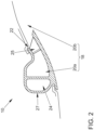
- FIG. 2 shows a schematic sectional view of a ventilation device 10.
- This view includes an air duct element 18, which in this example includes two air ducts 20a and 20b.
- Figure 2 only the exemplary positioning of these air channels 20a and 20b are shown.
- an air outflow point 22 can be seen.
- the air outflow point 22 is part of an air outflow element 24, which in this figure 2 is only shown as an example.
- Such an air outflow element 24 could also be referred to as a blade vent. It is conceivable that the air outflow element 24 has a different shape than that in Figure 2 has the shape shown.
- the arrangement of the air channels 20a, 20b and the air outflow element 24 are also shown here only as an example.
- a directional element 25 can also be seen in this exemplary embodiment.
- Such a directing element 25, as shown, can be at least partially integrated into the structure of the air outflow element 24 in such a way that components, for example, are also materially connected to this or other components. This is conceivable up to a degree of freedom such that at least one component of the directing element 25 remains separately adjustable.
- any other combination with regard to a spatial arrangement of these components of the ventilation device 10 is conceivable at this point, as long as it is ensured that at least two ventilation states, namely an indirect and a direct air flow, are made possible.
- the number of air channels in the air channel element 18 is not particularly limited. It would also be conceivable that the air duct element 18 is formed from just one air duct 20, which then supplies all of the intended air outflow points 22 of a ventilation device 10 with air.
- the air duct 20a is provided in the visible area of the side roof area 14.
- An outer area 27 of the air outflow element 24 could be designed in such a way that this outer area 27 is integrated into the appearance of the roof area 14 or cannot be visually distinguished from it.
- the air duct 20b is in the Figure 2 arranged outside the field of view and only shown using the conceivable positioning.
- such an air duct 20b could also be part of another component of the vehicle body.
- Such an air duct 20b could also be a separate component in the form of a tube, a tubular object or another geometric structure, which is designed to direct air to an intended air outflow point 22.
- a light production, not shown, could be provided, for example, using light elements in the form of light guides.
- the embodiment of Figure 2 is preferably intended for use in the roof area 14.
- a direct goal is to enable indirect ventilation through flow along a ceiling line in a selected ventilation state of the ventilation device 10.
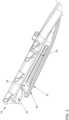
- an air outflow element 24 with an arranged directing element 25 is shown in a seat element 16.
- the straightening element 25 is shown here in the form of slats, which can be movably mounted. Due to their positioning or settings, the slats can ensure even air distribution along the ceiling line.
- electrical directivity can be implemented using an electrical device in the form of an electric motor in order to enable different ventilation styles.
- the air outflow element 24 is coupled to an air duct 20, which in turn is part of an air duct element 18.
- the air duct 20 can be supplied with air in relation to the image plane either from the left using a supply device (not shown) in the form of a rear air conditioning unit or from the right using a supply device (not shown) in the form of a front / center console air conditioning unit.
- a panel 28 is shown, which is arranged as a separating element between the air outflow element 24 with the arranged directing element 25 and a visible area of the seat element 16. In other words, this panel 28 limits the air outflow element 24 with the arranged directing element 25 in such a way that a viewer only perceives the ventilation device 10 due to the effect in the form of air provided and not visually as a separate component that is directly different from the other components of the seat element 16 visually highlights.
- the aperture 28 can also include a light element 30 in the form of a light guide, so that staging with light from the selected ventilation function is possible.
- a light element 30 in the form of a light guide, so that staging with light from the selected ventilation function is possible.
- the exemplary embodiment shown could thus enable air to be coupled into a seat structure, which could then be accompanied by a light display if a user has additionally selected this function. Integration into a back panel is therefore possible. It is also conceivable that a lighting display can be consciously switched on and off or is functionally related to a selected air conditioning program.
- FIG 4 shows a ventilation device 10 in the installed state. What can be seen is a window pane 32 in the rear of a motor vehicle and a headrest area 34 of a seat structure in the rear of this motor vehicle.
- the ventilation device 10 here comprises, for example, two air outflow elements 24 shown with respective directional elements 25, not shown in detail.
- the air outflow elements 24 with respective directional elements 25, not shown in detail are arranged in the visible area in such a way that they are clearly different from the rest of the roof area 14 visually highlight.
- the flow arrows 12 shown indicate both a possible direct and an indirect ventilation state.
- At least a portion of the window pane 32 is supplied with air in such a way that a desired effect, for example a clear view of the outside, is achieved. It is therefore also possible, for example, to implement indirect ventilation from the rear and from roof rails (not shown).
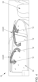
- the Figure 5a shows a sectional view of an air outflow element 24 with an arranged directing element 25 as components of a ventilation device 10, the directing element 25 being designed in the form of slats.
- the slats are divided into slats 36a in the visible area and slats 36b in the invisible area. Two slats 36a can be seen in the visible area and two slats 36b can also be seen in the invisible area. A total of four slats are therefore provided.
- the number of slats can differ in a variant not shown and can have any advantageous number of slats.
- the shape of the slats in this figure is also only to be seen as an example and any other shape of slats is also conceivable, as long as a desired direction of an air flow can be set.
- the slats 36b are therefore arranged in the background of the air outflow element 24. In the figure shown, one of these slats 36b is adjusted in such a way that it disappears at least partially or completely in a wall of the air outflow element 24, which is at least partially exposed to the air flow, and together with the wall of the air outflow element 24 has a desired effect the outflowing air has.
- the shape of the wall of the air outflow element 24 can accordingly be adapted to a shape of the slats, so that the interaction ultimately at least partially provides the desired effect on the outflowing air.
- at least one slat 36b can be adjusted in such a way that it represents an extension of an outer line of the wall or, together with the wall in which it is attached, has a common effect on outflowing air.
- Such a slat 36b can be rotatably fastened in the wall, for example with a hinge or a screw or other fastening means.
- the wall or generally the air outflow element 24 can have a recess in which the slat 36b can rest at least partially in a form-fitting manner in a foldable state.
- the opposite slat 36b is installed in a similar manner and shown in the figure.
- Different slats can be seen in front of the desired interaction of the overall concept, with a change in one slat having an effect on a resulting air flow profile, so that this state can be changed in turn by changing another slat.
- the slats 36a can at least partially take on the function of a decorative element in the visible area.
- the design of the directional element 25 can be carried out in such a way that an optical fit into a desired overall image of the interior of the motor vehicle is made possible.
- the slats 36a and 36b are in the Figure 5a adjusted so that a desired course of the flow arrow 12 shown is achieved.
- the slats 36a and 36b can be connected to the air outflow element 24, for example by means of hinges. Any other type of connection is also conceivable. It is conceivable that the slats 36a, 36b can assume a wide variety of positions in order to achieve a desired course of the flow arrow 12.
- the slats 36a, 36b can be adjustable independently of one another.
- the slats 36a, 36b can be moved at least partially coupled to one another. In other words, a deflection of any slat would then cause a movement of one or more other slats. It is also conceivable that all of the slats mentioned can be aligned in the desired manner using just one process. In particular, the interaction of two slats and the resulting arrangement relative to one another can produce a desired course of the flow arrow 12. It is also conceivable that the slats 36a, 36b are each individually adjustable and the interaction is controlled centrally, so that a resulting arrangement is ultimately established which produces a desired course of the flow arrow 12.
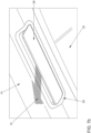
- the Figure 5b shows the air outflow element 24 with an arranged directing element 25 as components of a ventilation device 10 Figure 5a in a view from a viewer sitting in an interior area of a motor vehicle in which these components of the ventilation device are arranged.
- the slats 36a can be seen in the visible area, which at least partially take on the function of a decorative element.
- a decorative element preferably has the function of optically delimiting the ventilation device 10 to a visible interior area of the motor vehicle.
- a partial area of the air outflow element 24 can also be seen, which also takes on the function of a decorative element, at least in this partial area.
- the slats 36a can also completely take over the function of the decorative element.
- FIG 6a Another example of a directional element 25 can be seen in an installed state.
- This directing element 25 is arranged in an air outflow element 24. Both components are components of a ventilation device 10.
- the directional element 25 shown is arranged on the air outflow element 24 by means of a sliding mechanism 40, so that different ventilation states can be set either manually or electrically.
- the sliding mechanism 40 is arranged in the middle and has a straight course from the bottom right to the top left (relative to the image plane). In a variant not shown, this sliding mechanism 40 could also have an arcuate course or any other shape.
- the setting is such that a desired course of a flow arrow 12 is achieved.
- the directional element 25 includes a locking element 26, which can have the essentially shown shape of a diamond-shaped geometry.
- the sliding mechanism 40 is arranged approximately centrally on the locking element 26 in the figure.
- any other geometric shapes that allow direct or indirect air flow are also conceivable.
- the geometric shape is selected such that in a stop position, as shown in the exemplary embodiment, the locking element 26 rests at least substantially against a corresponding wall of the air outflow element 24, so that air passage is prevented at this point or at least largely avoided.
- the shape of the locking element 26 and the shape of the wall of the air outflow element 24, which is reached in a respective stop position by the locking element 26, must be at least partially matched to one another in a shape-fitting manner, so that essentially no air can pass through here.
- this is shown in that a flat side of the diamond-shaped body of the locking element 26 lies flat against the wall of the air outflow element 24, so that essentially no air escape can occur here and the flow arrow 12 can be steered in the desired direction as shown. It can be seen in particular how the air outflow element 24 and the directional element 25 together cause a desired flow pattern of an air stream to be established from within the ventilation device 10 into an interior area of a motor vehicle, not shown.
- a grip element 42 which can also only be referred to as a grip, can be seen on the directional element 25.
- This grip element 42 can be of one Users, for example, can be grasped manually in order to then move the directional element 25 into a desired position, so that a defined ventilation state is established.
- This ventilation state can then have, for example, a direct or indirect air flow.
- the directional element 25 can be actuated by means of an electrical device, for example an electric motor, with operation being possible, for example, via a climate control of an air conditioning system of a motor vehicle in which the ventilation device 10 is installed.
- the Figure 6b shows the air outflow element 24 with an arranged directing element 25 as components of a ventilation device 10 Figure 6a in a view from a viewer sitting in an interior area of a motor vehicle in which these components of the ventilation device are arranged.
- a roof area 14 and part of a window pane 32 can be seen.
- the directing element 25 is in the Figure 6b shown without a gripping element 42 and is in an upper position so that a flow arrow 12 points in the direction of the window pane 32.
- a direct ventilation state is therefore set on the window.
- the Figure 6c shows the air outflow element 24 with an arranged directing element 25 as components of a ventilation device 10 Figure 6a in a view from a viewer sitting in an interior area of a motor vehicle in which these components of the ventilation device 10 are arranged.
- a roof area 14 and part of a window pane 32 can be seen.
- the directing element 25 is in the Figure 6c shown without gripping element 42 and is in a lower position, so that a flow arrow 12 points in the direction of the roof area 14.
- An indirect ventilation state is therefore set.
- FIG 7a Another example of a directional element 25 can be seen in an installed state.
- This directing element 25 is arranged in an air outflow element 24. Both components are components of a ventilation device 10.
- the directional element 25 shown is arranged on the air outflow element 24 by means of a folding mechanism 44, so that different ventilation states can be set either manually or electrically.
- the setting is such that a desired course of a flow arrow 12 is achieved.
- the straightening element 25 comprises a locking element 26, which in the figure can essentially have the shape shown of a diamond or a diamond-shaped body or shape. This diamond-shaped shape is in the manner shown, particularly in the visible area, by means of a curved course of a front that is visible to the outside.
- the diamond-shaped locking element 26 is delimited in the visible area to the outside by a surface (outlined by a line in the figure), which bulges into the interior of a motor vehicle, not shown.
- This convex course can be adapted to the immediate surroundings of the interior of the motor vehicle in such a way that a smooth transition from the immediate surroundings to the locking element 26 occurs.
- this is indicated (relative to the image plane) in the upper left area, in that the arcuate line essentially represents an extension of an outer line from the roof area 14 shown at the top left.
- the locking element 26 is shaped in the visible area in such a way that a substantially flat transition from the roof area 14 to an outer surface of the locking element 26 is achieved.
- any other geometric shapes of the locking element 26 are also conceivable, which make it possible to enable a direct or indirect air flow.
- the aforementioned features can also occur or be taken into account with a different shape or only a slightly changed shape.
- the interaction between the course of the roof area 14 and an outer surface of the locking element 26 can be taken into account. It can be seen in particular how the air outflow element 24 and the directional element 25 together cause a desired flow pattern of an air stream to be established from within the ventilation device 10 into an interior area of a motor vehicle, not shown.
- the geometries of the two previously mentioned components are advantageously coordinated with one another.
- the folding mechanism 44 includes both a hinge 46, which is arranged centrally on the directing element 25, and an internal stand-up element 48, which is arranged on a rail element 50 in the air outflow element 24.
- the figure also only shows a possible further position for the folding mechanism 44. Any other intermediate position can be assumed between the current position shown and the further position.
- the mounting element 48 can then also assume a different position, although this position is not shown.
- the interaction between the folding mechanism 44 and the setting element 48 can take any arrangement that is made possible in accordance with the mechanical properties of the installed arrangement, so that a desired course of the flow arrow 12 is in turn achieved.
- a coupling (not shown) is conceivable. Any type of coupling element or even just one coupling element is conceivable.
- FIG. 7b shows the air outflow element 24 with an arranged directing element 25 as components of a ventilation device 10 Figure 7a in a view from a viewer sitting in an interior area of a motor vehicle in which these components of the ventilation device 10 are arranged.
- a roof area 14 and part of a window pane 32 can be seen.
- the directing element 25 is in the Figure 7b shown without gripping element 42 and is in a lower position, so that a flow arrow 12 points in the direction of the roof area 14.
- An indirect ventilation state is therefore set.
- the Figure 8 shows a schematic top view of a ventilation device 10 according to the invention.
- Two schematically illustrated air outflow elements 24 can be seen from which air flows out, the flow path in this exemplary embodiment being shown by means of dashed flow arrows 12. These air outflow elements 24 can also be referred to as static air outlets.
- a roof area 14 is shown schematically. This roof area 14 arches in relation to the image plane above two seat elements 16, which are also shown schematically.
- a directional element 25 is shown schematically on the left side above the seat element 16, which in this Figure 8 is shown as an arrow pointing downwards. This directional element 25 is in an extended state, so that the portion of the roof area 14 located immediately below curves downward.
- the installation of the directing element 25, which in this case can also be referred to as an actuator, requires that a change in shape of a roof lining occurs above this seat element 16, which is located on the left side, in order to achieve a targeted influence on the air flow by means of the To enable directing element 25 or the actuator.
- the directional element 25 can be folded out of the roof area 14 in order to bring about a desired ventilation state.
- a direct ventilation condition results, which can also be referred to as direct flow.
- a reciprocal, alternating air flow can be established or achieved on the left and right of the motor vehicle, which is reminiscent of air flows in a natural environment.
- the air outflow elements 24 on the left and right sides can, for example, be directed towards one another, so that the two competing air flows can cause air turbulence, so-called air rollers, in the center of the vehicle, which are perceived as pleasant by a passenger or generally by an occupant because their direction cannot be assigned and the speed is not constant.
Landscapes
- Engineering & Computer Science (AREA)
- Mechanical Engineering (AREA)
- Physics & Mathematics (AREA)
- Thermal Sciences (AREA)
- Power Engineering (AREA)
- Aviation & Aerospace Engineering (AREA)
- Transportation (AREA)
- Air-Conditioning For Vehicles (AREA)
Description
- Die Erfindung betrifft eine Belüftungsvorrichtung für einen Innenbereich eines Kraftfahrzeugs, insbesondere in einem Bereich einer zweiten Sitzreihe. Viele der heutigen bereits bekannten Klimatisierungsfunktionen stehen häufig nur den vorderen Sitzreihen zur Verfügung. Zum Beispiel sind zu diesem Zwecke Ausströmer mit Spot-Diffus-Funktion beziehungsweise zugfreier Belüftung und vollwertige Klimabedienteile zur Steuerung der Klimafunktion bekannt. Wenn für andere Bereiche in dem Innenbereich eines Kraftfahrzeuges Ausströmer vorgesehen sind, beispielsweise in Form von Fonds-Ausströmer, so ist die Größe, die Funktionen und die Position häufig zudem durch die Bauraumrestriktionen in der zweiten Sitzreihe stark eingeschränkt. So hat sich mittlerweile eine Entwicklung eingestellt, welche für den Fondbereich vollwertige Klimabedienteile, beispielsweise in Oberklassen-Fahrzeugen, mit Ausströmern in der B-Säule oder zugfreie Belüftung im Dachhimmel vorsehen. Diese Lösungen können dabei zusätzlich zu den Lösungen in einer Mittelkonsole vorgesehen sein. Zur Unterstützung für eine Klimatisierung sind auch Sitzheizungen, Sitzlüftungen oder Nackenheizungen bereits als bekannt anzusehen. Dabei ist die Erreichbarkeit der Insassen mittels B-Säulen-Ausströmern nur begrenzt und häufig nur asymmetrisch möglich. Zudem ist der Bauraum für zusätzliche Ausströmerfunktionen, beispielsweise diffuse oder zugfreie Führung der Luftströme, in diesem Bereich nicht unmittelbar vorhanden. Dies liegt unter anderem an der Position der Vordersitze beziehungsweise der Vordersitze allein sowie einem geringen Platz in der Mittelkonsole. Zudem ist häufig der Bauraum im Dach aufgrund eines vorhandenen Glasdaches begrenzt. Auch ist die Erreichbarkeit von Oberkörpern über Ausströmer in der Mittelkonsole nur begrenzt gewährleistet. So wurden in letzter Zeit vermehrt Lösungen vorgestellt, welche die zugfreie Belüftung im Dachhimmel in den Fokus der technischen Neuerungen stellen.
- So wird in der Druckschrift
DE 101 10 191 ein Fahrzeugdach mit einem Deckel zum Verschließen einer Dachöffnung offenbart, welches mindestens einen Luftführungskanal umfasst, um einen Luftstrom auf die Scheibe zu leiten. Auch ist zumindest ein Mittel zum Leiten wenigstens eines Teils des Luftstroms in Richtung eines Fahrzeuginsassen vorgesehen. Somit zeigt diese Lösung jeweils Möglichkeiten, eine direkte Luftführung bereitzustellen, so dass ein jeweiliges gewünschtes Ergebnis erreicht werden kann. Eine indirekte Luftführung der Luftströme ist nicht vorgesehen. - In der
DE 102 42 805 wird eine Belüftungseinrichtung für ein Kraftfahrzeug offenbart. Dabei ist ein Luftausströmer im Dachhimmel des Kraftfahrzeugs vorgesehen. Der Luftausströmer ist sichtbar im vorderen Ende eines Dachquerträgers angeordnet, wobei eine Dachquerträgerstruktur einschließlich des Dachquerträgers oder Teile derselben als Luftkanal dient. Die Belüftungseinrichtung dient zum indirekten und gleichförmigen Belüften des Fahrgastraums. Eine bewusste Trennung zwischen mindestens zwei Belüftungszuständen im Innenbereich ist nicht vorgesehen. Auch ist eine Unterscheidung zwischen einer direkten und einer indirekten Richtung von ausströmender Luft nicht vorgesehen. - In der
DE 10 2014 222 139 wird ein Kraftfahrzeug offenbart. Dabei soll eine Kühlung des Innenraums beziehungsweise der im Kraftfahrzeug befindlichen Personen mittels ausströmender Luft erfolgen, wobei an gegenüberliegenden Dachrahmenlängsabschnitten jeweils entsprechend der Anzahl an Sitzreihen Luftausströmungsöffnungen beidseitig vorgesehen sind. Ferner sind Mittel vorgesehen, welche eine Platzbelegung auf den vorhandenen Sitzen durch eine Person erkennen. Über eine Regelung kann so dann eine auf einem Sitz befindliche Person mit einem Luftmengenstrom angeströmt werden. Insbesondere ist dabei vorgesehen, dass eine indirekte Anströmung aus zwei sich aufeinander zu bewegenden Luftströmen resultiert. Je nach dem, wie diese beiden Luftströme über Drosselklappen und Luftförderanlagen gelenkt werden, kann ein gewünschtes Ergebnis erzielt werden. - Die
DE 10 2015 112 898 zeigt ein Klimatisierungs-und Belüftungssystem für ein Kraftfahrzeug. Dabei ist zumindest ein Fahrzeugsitz mittels eines Dachausströmersystems mit mindestens einem Dachausströmer vorgesehen. Dabei weist der Dachausströmer Mittel auf, welche eine Segmentierung der aktiven Ausströmflächen erlauben. In jedem Segment wirkt dabei eine vertikal in den Fahrzeuginnenraum wirkende Luftzufuhr mit einer Auswahl von Klimazonen. Ein großflächiger Dachausströmer weist eine Reihe von Öffnungen auf, welche je nach gewählter Segmentierung und entsprechender Klimazone einen Öffnungszustand einnehmen. Auch wird eine parallel zur Fahrtrichtung einzuteilende Segmentierung vorgeschlagen. Auch wird eine Beleuchtung vorgeschlagen, welche in Abhängigkeit der eingestellten Segmentierung geschaltet wird. Zusammen können aber der Dachausströmer und die Öffnungen eine in der jeweiligen Ausführungsvariante voreingestellte Richtung von vertikal beziehungsweise parallel zur Fahrtrichtung nicht ändern. Eine ungerichtete vertikale Luftzufuhr in den Fahrgastinnenraum wird lediglich aufgrund einer geringen bereitgestellten Luftmenge realisiert. Eine Veränderung der vertikalen Richtung in eine beispielsweise entlang des Dachhimmels verlaufende Strömung ist nicht vorgesehen. In diesem Zusammenhang kann auch die Beleuchtung einen solchen Zustand also nicht anzeigen. - Aus der Druckschrift
JP 2017 030 684 A - Aus der Druckschrift
JP H10 6745 A - Aus der Druckschrift
FR 2 845 318 A1 - Der Erfindung liegt nun die Aufgabe zugrunde, eine Belüftungsvorrichtung für einen Innenbereich eines Kraftfahrzeugs bereitzustellen, welche über einen hohen Komfort aufgrund einer flexiblen Einstellung von Luftströmen verfügt, welche für Insassen intuitiv erkennbar ist.
- Erfindungsgemäß ist vorgesehen, dass eine Belüftungsvorrichtung für einen Innenbereich eines Kraftfahrzeugs, insbesondere in einem Bereich einer zweiten Sitzreihe, bereitgestellt wird. Diese Belüftungsvorrichtung umfasst wenigstens ein Luftkanalelement, wenigstens eine mit einem ersten Ende des wenigstens einen Luftkanalelements gekoppelte Versorgungsvorrichtung als Teil einer Klimaanlage des Kraftfahrzeugs, wenigstens ein Luftausströmelement, welches an einem zweiten Ende des wenigstens einen Luftkanalelements gekoppelt ist und ausgelegt ist, im nicht sichtbaren Bereich des Innenbereichs des Kraftfahrzeugs angeordnet zu werden , wenigstens ein Richtelement und wenigstens ein Lichtelement. Die Anordnungen des wenigstens einen Richtelements und des wenigstens einen Luftausströmelements sind dabei ausgelegt, zusammen zu bewirken, dass die Belüftungsvorrichtung zumindest zwischen zwei Belüftungszuständen in dem Innenbereich des Kraftfahrzeugs stufenlos einstellbar ist, welche sich zumindest jeweils durch eine direkt in den Innenraum des Kraftfahrzeugs gerichtete und eine indirekt entlang eines für diese Zwecke ausgebildeten Dachhimmels gerichtete Richtung von ausströmender Luft bezogen auf einen Sitzbereich des Kraftfahrzeugs unterscheiden. Auf diese Weise ist es möglich, einen hohen Komfort aufgrund einer flexiblen Einstellung von Luftströmen, welche für Insassen intuitiv erkennbar ist, zu realisieren. Insbesondere ist eine Gestaltung des Luftauslasses in der Art möglich, dass die eigentliche Belüftungsfunktion im Deckenbereich nicht sichtbar ist. Somit stellt sich ein hoher Komfort aufgrund eines uneingeschränkten Innenraums ein. Beispielsweise kann der Mittelkonsolen-Ausströmer wegfallen, so dass der frei gewordene Bauraum anderweitig genutzt werden kann. Der Bauraum kann für neue Funktionen, beispielsweise Ablagen, genutzt werden. Es sind mittels der Erfindung Belüftungskonzepte für vollwertige Klimafunktionen in der zweiten Sitzreihe möglich. Auch ist eine ganzheitliche komfortbasierte Klimaregelung möglich. Dabei ist die Erfassung des thermischen Insassenkomforts und eine automatisierte Regelung aller Klimatisierungssysteme möglich. Dabei kann die Klimaanlage, da sie über die Versorgungsvorrichtung mit der Belüftungsvorrichtung gekoppelt ist, dazu verwendet werden, eine gewünschte Steuerung beziehungsweise Programmierung der Belüftungsvorrichtung auszuüben. Jegliche dabei in der Klimaanlage des Kraftfahrzeuges vorhandenen beziehungsweise mit dieser gekoppelten Module können somit in Interaktion mit der Belüftungsvorrichtung stehen. Zum Beispiel kann eine Sensorik zur Bewertung des thermischen Insassenkomforts vorgesehen sein. Dies kann beispielsweise in der Form einer Kombination von Feuchte und Temperatursensorik im Sitz und einer Infrarot-Sensorik für Gesichtshauttemperatur vorgesehen sein. Beispielsweise ist somit eine neue Klima-Architektur im Fond möglich, etwa durch eine Deckenbelüftung und Backpanel-Ausströmer mit programmierbaren Belüftungsstilen. Die Innenraum-Klimatisierung kann somit individuell auf die thermischen Komfortzustände der Insassen abgestimmt werden. Es lässt sich also eine komfortorientierte und prädiktive Klimaautomatik bereitstellen. Dabei kann die indirekte Belüftung durch eine Strömung entlang der Deckenlinie realisiert werden. Die Gestaltung des Dachhimmels kann beispielsweise in der Art sein, so dass sich ein Coanda-Effekt, also ein Anliegen der Luftströmung an der Deckenlinie, einstellt. Es wird also eine Strömung derart an der Deckenlinie angelegt, so dass sich diese im Raum verteilt und ein direktes Anströmen der Insassen vermieden wird. Es stellt sich eine indirekte beziehungsweise zugfreie Belüftungsfunktion für den Fahrzeugfond ein. Dabei ist beispielsweise eine Integration wenigstens einiger der vorgestellten Elemente in den seitlichen Deckenbereich vorgesehen, um Luft entlang der Deckenlinie von außen nach innen in den Innenraum des Kraftfahrzeuges zu fördern. Die Integration des wenigstens einen Luftkanalelements kann beispielsweise in den hinteren Dachbereich des Fahrzeuges, zum Beispiel über die B- oder C-Säule, vollzogen werden. Dabei kann die Gestaltung des Luftauslasses in Form des Luftausströmelements in der Art sein, dass eine eigentliche Belüftungsfunktion im Deckenbereich nicht sichtbar ist. Die technische Umsetzung kann bei einer stufenlosen Umschaltung derart sein, dass beispielsweise nur der Innenraum beziehungsweise nur eine Scheibe mit Luft beaufschlagt wird, als auch derart sein, dass beide, sowohl Innenraum als auch Scheibe beziehungsweise Insassen mit Luft beaufschlagt werden. Derartige Übergänge sind einstellbar. Das Richtelement ist beispielsweise im Deckenbereich derart angeordnet, so dass ein Strömungsbild des Luftausströmelements gezielt beeinflusst wird. Beispielsweise kann der Ort des Ablösens der Luftströmung gezielt beeinflusst werden. Somit lassen sich unterschiedliche Belüftungsfunktionen mit einem Ausströmkonzept realisieren. Zum Beispiel kann eine Schaltbarkeit zwischen Defog-/ Defrostfunktion und Belüftung des Innenraums realisiert werden. Wahlweise kann eine Umschaltbarkeit der Strömungsrichtung zwischen Innenraum und Seitenscheibe beziehungsweise gleichzeitiges Ausströmen der Luft Richtung Scheibe und Dachhimmel realisiert werden, um beispielsweise einen Eintrag der seitlichen Sonneneinstrahlung zu vermindern.
- Erfindungsgemäß ist vorgesehen, dass das wenigstens eine Richtelement ausgelegt ist, in einem nicht sichtbaren Dachbereich des Innenraums des Kraftfahrzeugs angeordnet zu werden, wobei das wenigstens eine Richtelement ausgelegt ist, bei einer Aktivierung des wenigstens einen Richtelements, eine Formveränderung des benachbarten sichtbaren Dachbereichs zu bewirken, so dass eine Richtung von ausströmender Luft aus dem wenigstens einen Luftausströmelement von einem Belüftungszustand zu einem weiteren Belüftungszustand einstellbar ist. Somit kann ein besonderer Komfort erzielt werden. Der Innenraum kann weitestgehend von den Insassen genutzt werden, da somit ein platzsparendes und kostengünstiges Konzept realisierbar ist.
- Die Erfindung kann beispielsweise in allen Fahrzeugen mit Sitzen im Fonds eingesetzt werden. Beispielsweise für Fahrzeuge der Mittel- und Oberklasse, welche ausreichend Raum für die Integration von Luftkanälen beziehungsweise Funktionsflächen ermöglichen. Auch kann die Erfindung in Bussen oder Kleinbussen verwendet werden. Denkbar wäre auch der Einsatz in Flugzeugen, Personenzügen und Traktoren.
- Weitere bevorzugte Ausgestaltungen der Erfindung ergeben sich aus den übrigen, in den Unteransprüchen genannten Merkmalen.
- In weiterer bevorzugter Ausgestaltung der Erfindung ist vorgesehen, dass in Abhängigkeit der zumindest zwei Belüftungszuständen eine Lichtinszenierung mittels des wenigstens einen Lichtelements einstellbar ist. Auf diese Weise kann ein entsprechender Belüftungszustand auch visuell den Insassen angezeigt werden. Das Lichtelement kann beispielsweise ein Lichtleiter oder ein Lichtsystem für die Inszenierung beziehungsweise die Anzeige der Belüftungsfunktion sein.
- In weiterer bevorzugter Ausgestaltung der Erfindung ist vorgesehen, dass das wenigstens eine Luftkanalelement und das wenigstens eine Luftausströmelement und das wenigstens eine Richtelement ausgelegt sind, in einem Dachbereich eines Innenbereichs des Kraftfahrzeugs angeordnet zu werden . Auf diese Weise ist eine besonders gute flexible Einstellung möglich, so dass ein besonders hoher Komfort erreicht werden kann.
- Auch ist in einer weiteren bevorzugten Ausgestaltung der Erfindung vorgesehen, dass das wenigstens eine Richtelement manuell oder elektrisch verstellbar ist, wobei im Falle einer elektrischen Verstellbarkeit die Belüftungsvorrichtung mit einer programmierbaren Klimaanlage derart gekoppelt ist, so dass die zumindest zwei Belüftungszustände und die Lichtinszenierung in Abhängigkeit eines aktivierten Programmes der Klimaanlage einstellbar sind. Auf diese Weise ist eine besonders gute flexible Einstellung möglich, so dass ein besonders hoher Komfort erreicht werden kann. Insbesondere kann auch erreicht werden, dass Insassen aufgrund der Lichtinszenierung intuitiv den jeweiligen Belüftungszustand erkennen können.
- Ferner ist in einer weiteren bevorzugten Ausgestaltung der Erfindung vorgesehen, dass die Versorgungsvorrichtung in Form eines Front/- Mittelkonsolen-Klimageräts oder in Form eines Heck-Klimageräts mit dem wenigstens einen Luftkanalelement gekoppelt ist. Auf diese Weise kann sich nicht nur ein hoher Komfort aufgrund einer flexiblen Einstellung von Luftströmen erreicht werden, sondern zugleich kann der Innenraum sehr effizient genutzt werden, da somit ein platzsparendes und kostengünstiges Konzept realisierbar ist.
- Schlussendlich ist in einer weiteren bevorzugten Ausgestaltung vorgesehen, dass ein Kraftfahrzeug mit einer Belüftungsvorrichtung nach einem der Ansprüche 1 - 5 bereitgestellt wird. In einem solchen Kraftfahrzeug lässt sich ein hoher Komfort aufgrund einer flexiblen Einstellung von Luftströmen erreichen, welche für Insassen intuitiv erkennbar ist.
- Die verschiedenen in dieser Anmeldung genannten Ausführungsformen der Erfindung sind, sofern im Einzelfall nicht anders ausgeführt, mit Vorteil miteinander kombinierbar.
- Die Erfindung wird nachfolgend in Ausführungsbeispielen anhand der zugehörigen Zeichnungen erläutert, wobei die
Figuren 1 bis 7 die grundsätzliche Funktionsweise von gattungsgemäßen Belüftungsvorrichtungen undFigur 8 eine erfindungsgemäße Belüftungsvorrichtung zeigen. Es zeigen: - Figur 1
- eine Belüftungsvorrichtung in einem eingebauten Zustand;
- Figur 2
- eine schematische Schnittansicht einer Belüftungsvorrichtung;
- Figur 3
- ein Luftausströmelement mit einem angeordneten Richtelement in einem Sitzelement;
- Figur 4
- eine Belüftungsvorrichtung im eingebauten Zustand;
- Figur 5a
- eine Schnittansicht eines Luftausströmelements mit einem angeordneten Richtelement;
- Figur 5b
- ein Richtelement in einem eingebauten Zustand;
- Figur 6a
- eine Schnittansicht eines Richtelements in einem eingebauten Zustand;
- Figur 6b
- ein Richtelement in einem eingebauten Zustand;
- Figur 6c
- ein Richtelement in einem eingebauten Zustand;
- Figur 7a
- eine Schnittansicht eines Richtelements in einem eingebauten Zustand;
- Figur 7b
- ein Richtelement in einem eingebauten Zustand;
- Figur 8
- eine schematische Draufsicht auf eine Belüftungsvorrichtung.
-
Figur 1 zeigt eine Belüftungsvorrichtung 10 in einem eingebauten Zustand in einem Innenbereich eines Kraftfahrzeugs. In der gezeigten Einstellungen zeigen Strömungspfeile 12 den Verlauf von ausströmender Luft aus der Belüftungsvorrichtung 10. In diesem Ausführungsbeispiel derFigur 1 sind die einzelnen Bestandteile der Belüftungsvorrichtung 10 sowohl in einem Dachbereich 14 des Innenbereichs als auch in einer jeweiligen Rückseite von Sitzelementen 16 im nicht sichtbaren Bereich angeordnet. Dabei ist die ausströmende Luft in einem Belüftungszustand, welcher jeweils eine indirekte Richtung der ausströmenden Luft vorsieht. Dabei sind die Strömungspfeile 12 nur beispielhaft dargestellt und zeigen lediglich einen von verschiedenen möglichen Verläufen einer sich einstellenden Richtung beziehungsweise eines zumindest teilweisen Verlaufs der ausströmenden Luft. Insbesondere die Strömungspfeile 12 an den Sitzelementen können auch zumindest teilweise in Richtung des Dachbereichs 14 zeigen, so dass sich ausströmende Luft ausgehend von den Sitzelementen auch entlang des Dachbereichs 14 ausbreiten könnte. Eine derartige Luftströmung würde sich also ausgehend von den Sitzelementen bis zu dem Dachbereich 14 ausbreiten und dort in verschiedene Richtungen abgelenkt werden, so dass sich eine indirekte Luftströmung einstellt. So kann sich beispielsweise auch eine Luftströmung entlang des Dachbereichs 14 einstellen. Der Dachbereich 14 bezieht alle Bereiche ein, welche sich oberhalb eines Innenbereichs eines Kraftfahrzeugs befinden. Insbesondere ist dies ein Bereich zwischen zwei sich gegenüberliegenden seitlichen Fensterscheiben. Je nach bevorzugter Richtung einer eingebauten Belüftungsvorrichtung 10 und im Zusammenspiel mit den einzelnen zuvor genannten Komponenten kann der Dachbereich 14 entsprechend für diese Zwecke ausgebildet sein, um beispielsweise auch eine indirekte Richtung der ausströmenden Luft vorzugeben. -
Figur 2 zeigt eine schematische Schnittansicht einer Belüftungsvorrichtung 10. Diese Ansicht umfasst dabei ein Luftkanalelement 18, welches in diesem Beispiel zwei Luftkanäle 20a und 20b umfasst. Dabei werden in derFigur 2 jeweils nur die beispielhaften Positionierungen dieser Luftkanäle 20a und 20b gezeigt. Des Weiteren ist ein Luftausströmungspunkt 22 zu erkennen. Der Luftausströmungspunkt 22 ist Teil eines Luftausströmelements 24, welches in dieserFigur 2 nur beispielhaft gezeigt wird. Ein solches Luftausströmelement 24 könnte auch als Blade-Ausströmer bezeichnet werden. Es ist vorstellbar, dass das Luftausströmelement 24 eine andere als die inFigur 2 gezeigte Form aufweist. Auch die Anordnung der Luftkanäle 20a, 20b und des Luftausströmelements 24 sind hier nur beispielhaft dargestellt. Ein Richtelement 25 ist in diesem Ausführungsbeispiel ebenfalls zu erkennen. Dabei kann ein solches Richtelement 25, wie dargestellt, zumindest teilweise in die Struktur des Luftausströmelements 24 derart integriert sein, dass Bestandteile sich beispielsweise auch stofflich an dieses oder andere Bauteile anschließen. Dies ist bis zu einem Freiheitsgrad derart denkbar, so dass zumindest ein Bestandteil des Richtelements 25 separat verstellbar verbleibt. Zu erkennen ist inFigur 2 insbesondere, inwiefern das Luftausströmungselement 24 und das Richtelement 25 zusammenwirken, so dass eine Luftströmung, welche sich an dem Luftausströmungspunkt 22 von einem nicht sichtbaren Bereich der Belüftungsvorrichtung 10 in Richtung eines sichtbaren Bereichs der Belüftungsvorrichtung 10 bewegt, gelenkt wird. Somit lassen sich je nach Position des Richtelements 25 unterschiedliche Belüftungszustände realisieren. Jegliche andere Kombination hinsichtlich einer räumlichen Anordnung dieser Bestandteile der Belüftungsvorrichtung 10 ist an dieser Stelle denkbar, solange dabei gewährleistet bleibt, dass zumindest zwei Belüftungszustände, nämlich eine indirekte und eine direkte Luftführung, ermöglicht wird. Die Anzahl der Luftkanäle in dem Luftkanalelement 18 ist nicht sonderlich beschränkt. Ebenso wäre es denkbar, dass das Luftkanalelement 18 aus nur einem Luftkanal 20 ausgebildet ist, welches dann entsprechend alle vorgesehenen Luftausströmungspunkte 22 einer Belüftungsvorrichtung 10 mit Luft versorgt. Der Luftkanal 20a ist im sichtbaren Bereich des seitlichen Dachbereichs 14 vorgesehen. Ein Außenbereich 27 des Luftausströmelements 24 könnte dabei derart gestaltet sein, dass dieser Außenbereich 27 sich sinngemäß in die Optik des Dachbereiches 14 eingliedert beziehungsweise optisch nicht von diesem zu unterscheiden ist. Der Luftkanal 20b ist in derFigur 2 außerhalb des Sichtbereiches angeordnet und lediglich mittels der denkbaren Positionierung dargestellt. Zum Beispiel könnte solch ein Luftkanal 20b auch Bestandteil von einem anderen Bauteil der Fahrzeugkarossiere sein. Auch könnte solch ein Luftkanal 20b ein separates Bauteil in der Form eines Rohres, eines röhrenförmigen Gegenstandes oder sonst eines geometrischen Gebildes sein, welches ausgebildet ist, Luft zu einem vorgesehenen Luftausströmungspunkt 22 zu leiten. Eine nicht gezeigte Lichtinszenierung könnte beispielsweise mittels Lichtelementen in Form von Lichtleitern vorgesehen sein. Das Ausführungsbeispiel vonFigur 2 ist vorzugweise für den Einsatz im Dachbereich 14 vorgesehen. Ein direktes Ziel ist es dabei, eine indirekte Belüftung durch Strömung entlang einer Deckenlinie in einem ausgewählten Belüftungszustand der Belüftungsvorrichtung 10 zu ermöglichen. - In
Figur 3 wird ein Luftausströmelement 24 mit einem angeordneten Richtelement 25 in einem Sitzelement 16 gezeigt. Das Richtelement 25 ist hier in Form von Lamellen , welche beweglich gelagert sein können, gezeigt. Die Lamellen können aufgrund ihrer Positionierungen beziehungsweise ihrer Einstellungen für eine gleichmäßige Luftverteilung entlang der Deckenlinie sorgen. Dabei kann beispielsweise eine elektrische Richtbarkeit mittels einer elektrischen Vorrichtung in Form eines Elektromotors realisiert werden, um somit verschiedene Belüftungsstile zu ermöglichen. Das Luftausströmelement 24 ist mit einem Luftkanal 20 gekoppelt, welches wiederum Bestandteil eines Luftkanalelements 18 ist. Die Versorgung des Luftkanals 20 mit Luft kann bezogen auf die Bildebene entweder von links mittels einer nicht gezeigten Versorgungsvorrichtung in Form eines Heck-Klimageräts vollzogen werden oder von rechts mittels einer nicht gezeigten Versorgungsvorrichtung in Form eines Front/ Mittelkonsolen-Klimageräts. Zudem wird inFigur 3 eine Blende 28 gezeigt, welche als Trennelement zwischen dem Luftausströmelement 24 mit dem angeordneten Richtelement 25 und einem sichtbaren Bereich des Sitzelements 16 angeordnet ist. Mit anderen Worten begrenzt diese Blende 28 das Luftausströmelement 24 mit dem angeordneten Richtelement 25 derart, dass ein Betrachter die Belüftungsvorrichtung 10 lediglich aufgrund der Wirkung in Form von bereitgestellter Luft wahrnimmt und nicht visuell als ein separates Bauteil, welches sich direkt von den übrigen Bauteilen des Sitzelements 16 optisch hervorhebt. Die Blende 28 kann zudem ein Lichtelement 30 in Form eines Lichtleiters umfassen, so dass eine Inszenierung mit Licht von der jeweilig gewählten Belüftungsfunktion möglich ist. Mittels der inFigur 3 gezeigten beispielhaften Ausführungsform könnte somit eine Einkopplung von Luft in eine Sitzstruktur ermöglicht werden, wobei diese dann mit einer Lichtinszenierung begleitet werden könnte, wenn ein Benutzer diese Funktion zusätzlich ausgewählt hat. Es ist somit eine Integration in ein Backpanel möglich. Vorstellbar ist es auch, dass eine Lichtinszenierung bewusst ein- und ausgeschaltet werden kann beziehungsweise in einem funktionalen Zusammenhang mit einem jeweils gewählten Programm einer Klimaanlage steht. -
Figur 4 zeigt eine Belüftungsvorrichtung 10 im eingebauten Zustand. Zu erkennen ist eine Fensterscheibe 32 in einem Fond von einem Kraftfahrzeug sowie ein Kopfstützbereich 34 einer Sitzstruktur im Fond von diesem Kraftfahrzeug. Die Belüftungsvorrichtung 10 umfasst hier beispielsweise zwei gezeigte Luftausströmelemente 24 mit jeweiligen nicht im Detail gezeigten Richtelementen 25. In diesem Beispiel sind die Luftausströmelemente 24 mit jeweiligen nicht im Detail gezeigten Richtelementen 25 im sichtbaren Bereich derart angeordnet, so dass sie sich deutlich von dem übrigen Dachbereich 14 optisch hervorheben. Die gezeigten Strömungspfeile 12 zeigen dabei sowohl einen möglichen direkten als auch einen indirekten Belüftungszustand an. Denkbar wäre, dass bei einem oder beiden der mindestens zwei einstellbaren Belüftungszuständen auch zumindest ein Teilbereich der Fensterscheibe 32 derart mit Luft beaufschlagt wird, so dass sich hier ein gewünschter Effekt, beispielsweise eine freie Sicht nach außen, einstellt. Somit ist es zum Beispiel auch möglich, eine indirekte Belüftung von hinten und aus nicht gezeigten Dachholmen zu realisieren. - Die
Figur 5a zeigt als Bestandteile einer Belüftungsvorrichtung 10 eine Schnittansicht eines Luftausströmelements 24 mit einem angeordneten Richtelement 25, wobei das Richtelement 25 in Form von Lamellen ausgebildet ist. Dabei sind die Lamellen in Lamellen 36a im sichtbaren Bereich und Lamellen 36b im nicht sichtbaren Bereich unterteilt. Im sichtbaren Bereich sind zwei Lamellen 36a zu erkennen und im nicht sichtbaren Bereich sind ebenfalls zwei Lamellen 36b zu erkennen. Insgesamt sind also vier Lamellen vorgesehen. Die Anzahl der Lamellen kann sich in einer nicht dargestellten Variante unterscheiden und jede dabei vorteilhafte Anzahl von Lamellen aufweisen. Auch die Form der Lamellen ist in dieser Figur nur als beispielhaft aufzufassen und es sind auch jegliche andere Formen von Lamellen denkbar, so lange sich somit eine gewünschte Richtung einer Luftströmung einstellen lässt. Die Lamellen 36b sind also im Hintergrund des Luftausströmelements 24 angeordnet. In der gezeigten Figur ist dabei eine dieser Lamellen 36b derart verstellt, so dass sie in einer Wandung von dem Luftausströmelement 24, welche zumindest teilweise der Luftströmung ausgesetzt ist, zumindest teilweise oder gänzlich verschwindet und mit der Wandung von dem Luftausströmelement 24 zusammen einen gewünschten Effekt auf die ausströmende Luft aufweist. Die Form der Wandung von dem Luftausströmelement 24 kann dementsprechend an eine Form der Lamellen angepasst sein, so dass das Zusammenwirken letztendlich den gewünschten Effekt auf die ausströmende Luft zumindest teilweise bereitstellt. Mit anderen Worten kann zumindest eine Lamelle 36b derart verstellt werden, so dass sie eine Verlängerung einer Außenlinie der Wandung darstellt beziehungsweise zusammen mit der Wandung, in welcher sie befestig ist, ein gemeinsame Auswirkung auf eine ausströmende Luft aufweist. Eine derartige Lamelle 36b kann beispielsweise mit einem Scharnier oder einer Schraube oder sonst einem Befestigungsmittel in der Wandung drehbar befestigt sein. Die Wandung beziehungsweise generell das Luftausströmelement 24 kann dabei eine Aussparung aufweisen, in welcher die Lamelle 36b in einem einklappbaren Zustand zumindest teilweise formschlüssig anliegen kann. Die gegenüberliegende Lamelle 36b ist in ähnlicher Weise verbaut und in der Figur dargestellt. In einer nicht dargestellten Variante ist es vorstellbar, dass nur eine von diesen mindestens zwei Lamellen 36b eine Zusammenwirkung mit der Wandung aufweist und die jeweils mindestens eine andere Lamelle 36b dann lediglich in einem benachbarten Bereich der Wandung anliegt. Diese und andere nicht gezeigte Anordnungen der verschiedenen Lamellen sind dabei jeweils vor dem gewünschten Zusammenwirken des Gesamtkonzepts zu sehen, wobei eine Veränderung einer Lamelle jeweils eine Auswirkung auf einen resultierenden Luftströmungsverlauf aufweist, so dass entsprechend über eine weitere Veränderung einer weiteren Lamelle dieser Zustand wiederum veränderbar ist. Die Lamellen 36a können im sichtbaren Bereich zumindest teilweise die Funktion eines Dekorelements übernehmen. Mit anderen Worten kann hier die Ausgestaltung des Richtelementes 25 derart erfolgen, so dass eine optische Einpassung in ein gewünschtes Gesamtbild des Innenraums des Kraftfahrzeugs ermöglicht wird. Die Lamellen 36a und 36b sind in derFigur 5a so eingestellt, dass sich ein gewünschter Verlauf des gezeigten Strömungspfeils 12 einstellt. Die Lamellen 36a und 36b können beispielsweise mittels von Scharnieren mit dem Luftausströmelement 24 verbunden sein. Jegliche andere Verbindungsart ist dabei ebenfalls denkbar. Es ist dabei vorstellbar, dass die Lamellen 36a, 36b verschiedenste Stellungen einnehmen können, um einen gewünschten Verlauf des Strömungspfeils 12 zu realisieren. Dabei können die Lamellen 36a, 36b unabhängig voneinander verstellbar sein. In einer anderen Variante ist es auch vorstellbar, dass die Lamellen 36a, 36b zumindest teilweise gekoppelt miteinander bewegbar sind. Mit anderen Worten würde dann eine Auslenkung einer beliebigen Lamelle eine Bewegung einer oder mehrerer anderer Lamellen bewirken. Auch ist es denkbar, dass somit nur mittels eines Vorgangs alle genannten Lamellen in gewünschter Weise ausgerichtet werden können. Insbesondere das Zusammenwirken von jeweils zwei Lamellen und die resultierende Anordnung zueinander kann einen gewünschten Verlauf des Strömungspfeils 12 hervorbringen. Auch ist vorstellbar, dass die Lamellen 36a, 36b jeweils einzeln verstellbar sind und das Zusammenwirken zentral gesteuert wird, so dass sich letztendlich eine resultierende Anordnung einstellt, welche einen gewünschten Verlauf des Strömungspfeils 12 hervorbringt. - Die
Figur 5b zeigt als Bestandteile einer Belüftungsvorrichtung 10 das Luftausströmelement 24 mit einem angeordneten Richtelement 25 vonFigur 5a in einer Sichtweise von einem Betrachter, welcher in einem Innenbereich eines Kraftfahrzeugs sitzt, in welchem diese Bauelemente der Belüftungsvorrichtung angeordnet sind. Zu erkennen sind die Lamellen 36a im sichtbaren Bereich, welche zumindest teilweise die Funktion eines Dekorelements übernehmen. Ein Dekorelement weist vorzugsweise die Funktion auf, die Belüftungsvorrichtung 10 optisch zu einem sichtbaren Innenbereich des Kraftfahrzeugs zu begrenzen. Zu Erkennen ist zudem ein Teilbereich des Luftausströmelements 24, welches zumindest in diesem Teilbereich ebenfalls die Funktion eines Dekorelements übernimmt. Vorstellbar sind jedoch auch andere, nicht gezeigte Anordnungen des Luftausströmelements 24 mit dem angeordneten Richtelement 25. Zum Beispiel können die Lamellen 36a ebenso vollständig die Funktion des Dekorelements übernehmen. - In
Figur 6a ist ein weiteres Beispiel eines Richtelements 25 in einem eingebauten Zustand zu erkennen. Dieses Richtelement 25 ist in einem Luftausströmelement 24 angeordnet. Beide Bauteile sind Bestandteile einer Belüftungsvorrichtung 10. Das gezeigte Richtelement 25 ist mittels eines Schiebemechanismus 40 an dem Luftausströmelement 24 angeordnet, so dass sich entweder manuell oder elektrisch verstellbar verschiedene Belüftungszustände einstellen lassen. In der Figur ist der Schiebemechanismus 40 mittig angeordnet und weist einen geraden Verlauf von (bezogen auf die Bildebene) rechts unten nach links oben auf. In einer nicht dargestellten Variante könnte dieser Schiebemechanismus 40 auch einen bogenförmigen Verlauf oder jeglichen andersförmigen Verlauf aufweisen. In dem gezeigten Beispiel derFigur 6a ist die Einstellung derart, so dass sich ein gewünschter Verlauf eines Strömungspfeils 12 einstellt. Das Richtelement 25 umfasst ein Riegelelement 26, welches die im Wesentlichen gezeigte Form einer rautenförmigen Geometrie aufweisen kann. Zudem ist in der Figur der Schiebemechanismus 40 etwa mittig an dem Riegelelement 26 angeordnet. Auch hier sind weitere nicht gezeigte Variationen denkbar. Vorstellbar sind jedoch auch jegliche andere geometrische Formen, welche es erlauben, eine direkte beziehungsweise indirekte Luftströmung zu ermöglichen. Dabei ist jedoch zu beachten, dass die geometrische Form derart gewählt ist, dass sich in einer Anschlagposition, wie sie in dem Ausführungsbeispiel darstellt, das Riegelelement 26 an eine entsprechende Wandung des Luftausströmelements 24 zumindest wesentlich anliegt, so dass an dieser Stelle ein Luftdurchtritt verhindert oder zumindest größtenteils vermieden wird. Mit anderen Worten sind an dieser Stelle die Form des Riegelelements 26 und die Form der Wandung des Luftausströmelements 24, welche in einer jeweiligen Anschlagposition von dem Riegelelement 26 erreicht wird, zumindest teilweise formpassend aufeinander abzustimmen, so dass sich hier im Wesentlichen kein Luftdurchtritt einstellen kann. In der Figur ist dies dadurch gezeigt, dass eine flache Seite des rautenförmigen Körpers des Riegelelements 26 flach an die Wandung des Luftausströmelements 24 anlegt, so dass sich hier im Wesentlichen kein Luftaustritt einstellen kann und der Strömungspfeil 12 wie dargestellt in die gewünschte Richtung lenken lässt. Zu erkennen ist insbesondere, wie das Luftausströmelement 24 und das Richtelement 25 zusammen bewirken, dass sich ein gewünschter Strömungsverlauf eines Luftstroms von innerhalb der Belüftungsvorrichtung 10 in einen nicht gezeigten Innenbereich eines Kraftfahrzeugs einstellt. Dazu sind hier beispielsweise die Geometrien der beiden zuvor genannten Bauteile in vorteilshafter Weise aufeinander abgestimmt. Ferner ist ein Anfasselement 42, welches auch nur als Anfasser bezeichnet werden kann, an dem Richtelement 25 zu erkennen. Dieses Anfasselement 42 kann von einem Benutzer beispielsweise händisch umfasst werden, um daraufhin das Richtelement 25 in eine gewünschte Position zu bewegen, so dass sich ein definierter Belüftungszustand einstellt. Dieser Belüftungszustand kann dann beispielsweise eine direkte beziehungsweise indirekte Luftströmung aufweisen. Es ist aber auch vorstellbar, dass sich das Richtelement 25 mittels einer elektrischen Vorrichtung beispielsweise eines Elektromotors betätigen lässt, wobei eine Bedienung zum Beispiel über eine Klimabedienung einer Klimaanlage eines Kraftfahrzeugs, in dem die Belüftungsvorrichtung 10 eingebaut ist, möglich ist. - Die
Figur 6b zeigt als Bestandteile einer Belüftungsvorrichtung 10 das Luftausströmelement 24 mit einem angeordneten Richtelement 25 vonFigur 6a in einer Sichtweise von einem Betrachter, welcher in einem Innenbereich eines Kraftfahrzeugs sitzt, in welchem diese Bauelemente der Belüftungsvorrichtung angeordnet sind. Es ist ein Dachbereich 14 und ein Teil einer Fensterscheibe 32 zu erkennen. Das Richtelement 25 ist in derFigur 6b ohne Anfasselement 42 abgebildet und befindet sich in einer oberen Position, so dass ein Strömungspfeil 12 in Richtung der Fensterscheibe 32 zeigt. Es ist somit ein direkter Belüftungszustand auf die Scheibe eingestellt. - Die
Figur 6c zeigt als Bestandteile einer Belüftungsvorrichtung 10 das Luftausströmelement 24 mit einem angeordneten Richtelement 25 vonFigur 6a in einer Sichtweise von einem Betrachter, welcher in einem Innenbereich eines Kraftfahrzeugs sitzt, in welchem diese Bauelemente der Belüftungsvorrichtung 10 angeordnet sind. Es ist ein Dachbereich 14 und ein Teil einer Fensterscheibe 32 zu erkennen. Das Richtelement 25 ist in derFigur 6c ohne Anfasselement 42 abgebildet und befindet sich in einer unteren Position, so dass ein Strömungspfeil 12 in Richtung des Dachbereichs 14 zeigt. Es ist somit ein indirekter Belüftungszustand eingestellt. - In
Figur 7a ist ein weiteres Beispiel eines Richtelements 25 in einem eingebauten Zustand zu erkennen. Dieses Richtelement 25 ist in einem Luftausströmelement 24 angeordnet. Beide Bauteile sind Bestandteile einer Belüftungsvorrichtung 10. Das gezeigte Richtelement 25 ist mittels eines Klappmechanismus 44 an dem Luftausströmelement 24 angeordnet, so dass sich entweder manuell oder elektrisch verstellbar verschiedene Belüftungszustände einstellen lassen. In dem gezeigten Beispiel derFigur 7a ist die Einstellung derart, so dass sich ein gewünschter Verlauf eines Strömungspfeils 12 einstellt. Das Richtelement 25 umfasst ein Riegelelement 26, welches in der Figur im Wesentlichen die gezeigte Form einer Raute beziehungsweise eines rautenförmigen Körpers beziehungsweise Form aufweisen kann. Diese rautenförmige Form ist in der dargestellten Weise insbesondere im Sichtbereich mittels eines kurvenförmigen Verlaufs einer nach außen hin sichtbaren Front abgewandelt. Mit anderen Worten ist das rautenförmige Riegelelement 26 im sichtbaren Bereich nach außen durch eine Fläche (in der Figur durch eine Linie skizziert) begrenzt, welche sich in den Innenbereich eines nicht weiter dargestellten Kraftfahrzeugs vorwölbt. Dieser konvexe Verlauf kann sich entsprechend an die unmittelbare Umgebung des Innenbereichs des Kraftfahrzeugs derart angepasst darstellen, so dass sich ein fließender Übergang von der unmittelbaren Umgebung zu dem Riegelelement 26 einstellt. In der gezeigten Figur ist dies (bezogen auf die Bildebene) im linken oberen Bereich angedeutet, indem die bogenförmige Linie im Wesentlichen als Verlängerung einer Außenlinie von dem links oben gezeigten Dachbereich 14 darstellt. Mit anderen Worten ist das Riegelelement 26 derartig im sichtbaren Bereich ausgeformt, so dass sich ein im Wesentlichen ebener Übergang von dem Dachbereich 14 zu einer Außenfläche des Riegelelements 26 einstellt. Vorstellbar sind jedoch auch jegliche andere geometrische Formen des Riegelelements 26, welche es erlauben, eine direkte beziehungsweise indirekte Luftströmung zu ermöglichen. Die zuvor genannten Merkmale können sich auch bei einer anderen Formgebung oder einer nur leicht veränderten Formgebung einstellen beziehungsweise berücksichtigt werden. Insbesondere das Zusammenspiel zwischen dem Verlauf des Dachbereichs 14 und einer Außenfläche des Riegelelements 26 kann dabei berücksichtigt werden. Zu erkennen ist insbesondere, wie das Luftausströmelement 24 und das Richtelement 25 zusammen bewirken, dass sich ein gewünschter Strömungsverlauf eines Luftstroms von innerhalb der Belüftungsvorrichtung 10 in einen nicht gezeigten Innenbereich eines Kraftfahrzeugs einstellt. Dazu sind hier beispielsweise die Geometrien der beiden zuvor genannten Bauteile in vorteilshafter Weise aufeinander abgestimmt. Der Klappmechanismus 44 umfasst in diesem Beispiel sowohl ein Scharnier 46, welches mittig an dem Richtelement 25 angeordnet ist, als auch ein innenliegendes Aufstellelement 48, welches auf einem Schienenelement 50 in dem Luftausströmelement 24 angeordnet ist. In der Figur ist zudem lediglich für den Klappmechanismus 44 eine mögliche weitere Stellung gezeigt. Zwischen der aktuellen dargestellten Stellung und der weiteren Stellung kann jegliche weitere Zwischenposition eingenommen werden. Das Aufstellelement 48 kann dann ebenfalls eine andere Stellung einnehmen, wobei diese Stellung nicht gezeigt wird. Dabei kann das Zusammenwirken zwischen dem Klappmechanismus 44 und dem Aufstellelement 48 jegliche Anordnung einnehmen, welche gemäß den mechanischen Eigenschaften der eingebauten Anordnung ermöglicht wird, so dass sich wiederum ein gewünschter Verlauf des Strömungspfeils 12 einstellt. Auch hier ist eine nicht weiter dargestellte Kopplung denkbar. Jegliche Art von Kopplungselementen oder auch nur ein Kopplungselement ist dabei vorstellbar. Auch ist wiederum eine individuell steuerbare Anordnung mit einer voneinander unabhängigen Bewegungsart denkbar, wobei dann die spezifische Anordnung zentral gesteuert wird, so dass sich wiederum ein gewünschter Verlauf des Strömungspfeils 12 einstellt beziehungsweise einstellen lässt. Je nach Intensität der angelegten Strömung und insbesondere durch das Zusammenwirken von dem Klappmechanismus 44 und dem Aufstellelement 48 lassen sich somit stufenlos verschiedenste Lüftungskonzepte einstellen, so dass eine besonders flexible und einfach zu bedienende Anordnung bereitgestellt werden kann. DieFigur 7b zeigt als Bestandteile einer Belüftungsvorrichtung 10 das Luftausströmelement 24 mit einem angeordneten Richtelement 25 vonFigur 7a in einer Sichtweise von einem Betrachter, welcher in einem Innenbereich eines Kraftfahrzeugs sitzt, in welchem diese Bauelemente der Belüftungsvorrichtung 10 angeordnet sind. Es ist ein Dachbereich 14 und ein Teil einer Fensterscheibe 32 zu erkennen. Das Richtelement 25 ist in derFigur 7b ohne Anfasselement 42 abgebildet und befindet sich in einer unteren Position, so dass ein Strömungspfeil 12 in Richtung des Dachbereichs 14 zeigt. Es ist somit ein indirekter Belüftungszustand eingestellt. - Die
Figur 8 zeigt eine schematische Draufsicht auf eine erfindungsgemäße Belüftungsvorrichtung 10. Zu erkennen sind zwei schematisch dargestellte Luftausströmelemente 24 aus welchen Luft ausströmt, wobei der Strömungsweg in diesem Ausführungsbeispiel mittels gestrichelter Strömungspfeile 12 dargestellt ist. Diese Luftausströmelemente 24 können auch als statische Ausströmer bezeichnet werden. Ferner ist schematisch ein Dachbereich 14 dargestellt. Dieser Dachbereich 14 wölbt sich bezogen auf die Bildebene oberhalb von zwei ebenfalls schematisch dargestellten Sitzelementen 16. Wiederum bezogen auf die Bildebene ist auf der linken Seite oberhalb des Sitzelements 16 schematisch ein Richtelement 25 dargestellt, welches in dieserFigur 8 als nach unten weisender Pfeil dargestellt ist. Dieses Richtelement 25 befindet sich in einem ausgefahrenen Zustand, so dass sich der unmittelbar darunter befindliche Teilbereich des Dachbereichs 14 nach unten wölbt. Mit anderen Worten bedingt die Aufstellung des Richtelements 25, welches in diesem Fall auch als Aktuator bezeichnet werden kann, dass sich eine Formveränderung von einem Dachhimmel über diesem, auf der linken Seite befindlichen, Sitzelement 16 einstellt, um so eine gezielte Beeinflussung der Luftströmung mittels des Richtelements 25 beziehungsweise des Aktuators zu ermöglichen. In einer nicht dargestellten Alternative ist es auch vorstellbar, dass sich das Richtelement 25 aus dem Dachbereich 14 herausklappen lässt, um somit einen gewünschten Belüftungszustand herbeizuführen. In beiden Fällen resultiert ein direkter Belüftungszustand, welcher auch als direkte Anströmung bezeichnet werden kann. Durch das Ausstellen eines oder mehrerer solcher Richtelemente 25 hinter der Luftaustrittsfläche lässt sich also ein direkter Belüftungszustand ermöglichen. Gegenüberliegend auf der rechten Seite bezogen auf die Bildebene ist kein Richtelement 25 gezeigt, da dieses sich in einem nicht aktivierten Zustand befindet. Somit stellt sich ein indirekter Strömungsverlauf der aus dem Luftausströmelement 24 ausströmenden Luft ein, so dass ein Innenbereich des Kraftfahrzeugs, welcher auch als Kabine bezeichnet werden kann, mit einer indirekten Belüftung ermöglicht wird. Diese indirekte Belüftung hat also zur Folge, dass sich die ausströmende Luft entlang des Dachhimmels ausbreitet, da der Dachhimmel also nunmehr glatt und ohne Strömungshindernisse ist. Dabei kann auch in diesem Beispiel entweder eine manuelle Einstellbarkeit oder eine elektrische Betätigung, etwa über die Klimabedienung, vorgesehen sein. Da sich die Luftausströmelemente 24 gegenüberliegen, kann sich auch eine Richtbarkeit der Belüftungsvorrichtung 10 einstellen, welche sich wechselseitig beziehungsweise durch eine alternierende Luftströmung auszeichnet. Mit anderen Worten kann sich eine wechselseitige, alternierende Luftströmung links und rechts im Kraftfahrzeug einstellen beziehungsweise erzielt werden, welche an Luftströmungen in einer natürlichen Umgebung erinnert. Die Luftausströmelemente 24 der linken und rechten Seite können beispielsweise aufeinander gerichtet sein, so dass es durch die beiden konkurrierenden Luftströme zu Verwirbelungen der Luft, sogenannten Luftwalzen, in der Fahrzeugmitte kommen kann, wobei diese von einem Fahrgast oder allgemein von einem Insassen als angenehm wahrgenommen werden kann, da deren Richtung nicht zuordenbar ist und die Geschwindigkeit nicht konstant ist. -
- 10
- Belüftungsvorrichtung
- 12
- Strömungspfeile
- 14
- Dachbereich
- 16
- Sitzelement
- 18
- Luftkanalelement
- 20
- Luftkanal
- 20a
- Luftkanal
- 20b
- Luftkanal
- 22
- Luftausströmungspunkt
- 24
- Luftausströmelement
- 25
- Richtelement
- 26
- Riegelelement
- 27
- Außenbereich
- 28
- Blende
- 30
- Lichtelement
- 32
- Fensterscheibe
- 34
- Kopfstützbereich
- 36a
- Lamellen im sichtbaren Bereich
- 36b
- Lamellen im nicht sichtbaren Bereich
- 40
- Schiebemechanismus
- 42
- Anfasselement
- 44
- Klappmechanismus
- 46
- Scharnier
- 48
- Aufstellelement
- 50
- Schienenelement
Claims (5)
- Belüftungsvorrichtung (10) für einen Innenbereich eines Kraftfahrzeugs, insbesondere in einem Bereich einer zweiten Sitzreihe, umfassend wenigstens ein Luftkanalelement (18), wenigstens eine mit einem ersten Ende des wenigstens einen Luftkanalelements (18) gekoppelte Versorgungsvorrichtung als Teil einer Klimaanlage des Kraftfahrzeugs, wenigstens ein Luftausströmelement (24), welches an einem zweiten Ende des wenigstens einen Luftkanalelements (18) gekoppelt ist und ausgelegt ist, im nicht sichtbaren Bereich des Innenbereichs des Kraftfahrzeugs angeordnet zu werden , wenigstens ein Richtelement (25) und wenigstens ein Lichtelement (30), wobei die Anordnungen des wenigstens einen Richtelements (25) und des wenigstens einen Luftausströmelements (24) ausgelegt sind, zusammen zu bewirken, dass die Belüftungsvorrichtung (10) zumindest zwischen zwei Belüftungszuständen in dem Innenbereich des Kraftfahrzeugs stufenlos einstellbar ist, welche sich zumindest jeweils durch eine direkt in den Innenraum des Kraftfahrzeugs gerichtete und eine indirekt entlang eines für diese Zwecke ausgebildetem Dachhimmels gerichtete Richtung von ausströmender Luft bezogen auf einen Sitzbereich des Kraftfahrzeugs unterscheiden, dadurch gekennzeichnet, dass das wenigstens eine Richtelement (25) ausgelegt ist, in einem nicht sichtbaren Dachbereich (14) des Innenraums des Kraftfahrzeugs angeordnet zu werden, wobei das wenigstens eine Richtelement (25) ausgelegt ist, bei einer Aktivierung des wenigstens einen Richtelements (25) eine Formveränderung des benachbarten sichtbaren Dachbereichs (14) zu bewirken, so dass eine Richtung von ausströmender Luft aus dem wenigstens einen Luftströmelement (24) von einem Belüftungszustand zu einem weiteren Belüftungszustand einstellbar ist.
- Belüftungsvorrichtung (10) nach Anspruch 1, dadurch gekennzeichnet, dass in Abhängigkeit der zumindest zwei Belüftungszuständen eine Lichtinszenierung mittels des wenigstens einen Lichtelements (30) einstellbar ist.
- Belüftungsvorrichtung nach Anspruch 1 oder Anspruch 2, dadurch gekennzeichnet, dass das wenigstens eine Luftkanalelement (18) und das wenigstens eine Luftausströmelement (24) und das wenigstens eine Richtelement (25) ausgelegt sind, in einem Dachbereich (14) eines Innenbereichs des Kraftfahrzeugs
angeordnet zu werden. - Belüftungsvorrichtung (10) nach einem der vorherigen Ansprüche, dadurch gekennzeichnet, dass das wenigstens eine Richtelement (25) manuell oder elektrisch verstellbar ist, wobei im Falle einer elektrischen Verstellbarkeit die Belüftungsvorrichtung (10) mit einer programmierbaren Klimaanlage derart gekoppelt ist, sodass die zumindest zwei Belüftungszustände und die Lichtinszenierung in Abhängigkeit eines aktivierten Programmes der Klimaanlage einstellbar sind.
- Belüftungsvorrichtung (10) nach einem der vorherigen Ansprüche, dadurch gekennzeichnet, dass die Versorgungsvorrichtung in Form eines Front/- Mittelkonsolen-Klimageräts oder in Form eines Heck-Klimageräts mit dem wenigstens einen Luftkanalelement (18) gekoppelt ist.
Applications Claiming Priority (2)
| Application Number | Priority Date | Filing Date | Title |
|---|---|---|---|
| DE102018106156.0A DE102018106156B4 (de) | 2018-03-16 | 2018-03-16 | Belüftungsvorrichtung für einen Innenbereich eines Kraftfahrzeugs, insbesondere in einem Bereich einer zweiten Sitzreihe |
| PCT/EP2019/056373 WO2019175294A1 (de) | 2018-03-16 | 2019-03-14 | Belüftungsvorrichtung für einen innenbereich eines kraftfahrzeugs |
Publications (2)
| Publication Number | Publication Date |
|---|---|
| EP3765320A1 EP3765320A1 (de) | 2021-01-20 |
| EP3765320B1 true EP3765320B1 (de) | 2024-02-28 |
Family
ID=66001165
Family Applications (1)
| Application Number | Title | Priority Date | Filing Date |
|---|---|---|---|
| EP19715001.4A Active EP3765320B1 (de) | 2018-03-16 | 2019-03-14 | Belüftungsvorrichtung für einen innenbereich eines kraftfahrzeugs |
Country Status (5)
| Country | Link |
|---|---|
| US (1) | US11904658B2 (de) |
| EP (1) | EP3765320B1 (de) |
| CN (1) | CN111770846B (de) |
| DE (1) | DE102018106156B4 (de) |
| WO (1) | WO2019175294A1 (de) |
Families Citing this family (8)
| Publication number | Priority date | Publication date | Assignee | Title |
|---|---|---|---|---|
| DE102019211575A1 (de) * | 2019-08-01 | 2021-02-04 | Brose Fahrzeugteile SE & Co. Kommanditgesellschaft, Coburg | Belüftungsvorrichtung für ein Fahrzeug und Verfahren zur Belüftung |
| DE102020002486A1 (de) * | 2019-12-20 | 2021-06-24 | Gentherm Gmbh | Belüftungseinrichtung für eine Kabine eines Fahrzeugs |
| CA3120925A1 (en) * | 2020-06-05 | 2021-12-05 | Polaris Industries Inc. | Frame for an off-road vehicle |
| KR20220057695A (ko) * | 2020-10-30 | 2022-05-09 | 현대자동차주식회사 | 천장형 벤트장치 |
| DE102021110951A1 (de) | 2021-04-28 | 2022-11-03 | Kautex Textron Gmbh & Co. Kg | Ausströmungseinrichtung für ein Dachhimmelsystem und Dachhimmelsystem zur Belüftung einer Fahrgastzelle mit wenigstens einer Ausströmungseinrichtung |
| US20240059122A1 (en) * | 2022-08-18 | 2024-02-22 | Apple Inc. | Vent switching between indirect and direct modes |
| KR102527165B1 (ko) * | 2022-10-17 | 2023-04-28 | 주식회사 서연이화 | 차량용 독립 공기 조화 시트 |
| DE102023004293A1 (de) | 2023-10-26 | 2025-04-30 | Mercedes-Benz Group AG | Dachbelüftungssystem für einen Personenkraftwagen |
Family Cites Families (20)
| Publication number | Priority date | Publication date | Assignee | Title |
|---|---|---|---|---|
| DE3714223C1 (de) * | 1987-04-29 | 1988-12-22 | Fraunhofer Ges Forschung | Anordnung zur Luftfuehrung in Fahrzeugraeumen |
| JPH106745A (ja) | 1996-06-24 | 1998-01-13 | Denso Corp | 空気調和装置 |
| US6416116B1 (en) * | 2000-02-03 | 2002-07-09 | New Flyer Industries Limited | Interior structure of a mass transit vehicle |
| DE10110191A1 (de) | 2001-03-02 | 2002-09-12 | Webasto Vehicle Sys Int Gmbh | Fahrzeugdach mit einem Deckel zum Verschließen einer Dachöffnung |
| DE10239387B4 (de) | 2002-03-01 | 2011-04-07 | Volkswagen Ag | Versenkbarer Schalter |
| FR2845318B1 (fr) | 2002-10-04 | 2006-05-19 | Valeo Climatisation | Dispositif de regulation thermique pour habitacle de vehicule automobile utilisant au moins un siege |
| DE102004004387B4 (de) * | 2004-01-29 | 2006-09-14 | Daimlerchrysler Ag | Fahrzeugsitz |
| US6966829B1 (en) * | 2004-05-27 | 2005-11-22 | Lear Corporation | HVAC system for a vehicle with concealed vents |
| JP3156703U (ja) * | 2009-10-28 | 2010-01-14 | 豊和化成株式会社 | レジスタ |
| US9102215B2 (en) * | 2011-10-17 | 2015-08-11 | Ford Global Technologies, Llc | Airflow control in floor mode for vehicle with multiple seating rows |
| US20150140915A1 (en) * | 2013-11-19 | 2015-05-21 | Atieva, Inc. | Vehicle Seat Ventilation System |
| DE102014222139B4 (de) | 2014-10-30 | 2025-07-10 | Bayerische Motoren Werke Aktiengesellschaft | Kraftfahrzeug |
| JP2017030684A (ja) | 2015-08-05 | 2017-02-09 | トヨタ自動車株式会社 | 天井用空調レジスタ |
| DE102015112898A1 (de) | 2015-08-05 | 2017-02-09 | Dr. Schneider Kunststoffwerke Gmbh | Klimatisierungs- und Belüftungssystem für ein Kraftfahrzeug |
| WO2017208658A1 (ja) * | 2016-06-03 | 2017-12-07 | 株式会社デンソー | 操作デバイス |
| US20180194194A1 (en) * | 2016-07-28 | 2018-07-12 | Faraday&Future Inc. | Air control method and system based on vehicle seat status |
| DE102018222852A1 (de) * | 2018-12-21 | 2020-06-25 | Brose Fahrzeugteile SE & Co. Kommanditgesellschaft, Coburg | Kraftfahrzeugbaugruppe mit einer Mittelkomponente |
| KR102673008B1 (ko) * | 2019-05-21 | 2024-06-05 | 현대자동차주식회사 | 루프 벤트 |
| US11760158B2 (en) * | 2019-10-07 | 2023-09-19 | Keystone Rv Company | Vent covers for recreational vehicle ductwork |
| JP2021160618A (ja) * | 2020-04-01 | 2021-10-11 | トヨタ自動車株式会社 | 車両用機器操作装置 |
-
2018
- 2018-03-16 DE DE102018106156.0A patent/DE102018106156B4/de active Active
-
2019
- 2019-03-14 EP EP19715001.4A patent/EP3765320B1/de active Active
- 2019-03-14 CN CN201980014446.0A patent/CN111770846B/zh active Active
- 2019-03-14 WO PCT/EP2019/056373 patent/WO2019175294A1/de not_active Ceased
-
2020
- 2020-09-16 US US17/023,325 patent/US11904658B2/en active Active
Also Published As
| Publication number | Publication date |
|---|---|
| CN111770846A (zh) | 2020-10-13 |
| WO2019175294A1 (de) | 2019-09-19 |
| DE102018106156B4 (de) | 2026-03-12 |
| DE102018106156A1 (de) | 2019-09-19 |
| CN111770846B (zh) | 2023-11-07 |
| US11904658B2 (en) | 2024-02-20 |
| US20210001687A1 (en) | 2021-01-07 |
| EP3765320A1 (de) | 2021-01-20 |
Similar Documents
| Publication | Publication Date | Title |
|---|---|---|
| EP3765320B1 (de) | Belüftungsvorrichtung für einen innenbereich eines kraftfahrzeugs | |
| DE112016003095B4 (de) | Klimatisierungs- und Belüftungssystem für ein Kraftfahrzeug | |
| DE102012021519B4 (de) | Lüftungssystem für ein Kraftfahrzeug sowie Verfahren zum Betreiben eines solchen | |
| DE102012108962B4 (de) | Passagier-Versorgungseinheit für Land-, Luft- und Wasserfahrzeuge | |
| EP3028894B1 (de) | Klimatisierungseinrichtung für ein kraftfahrzeug | |
| DE102005002062A1 (de) | Verfahren zur Regelung von Luftdüsen zur Klimatisierung eines Kraftfahrzeugs | |
| DE102016220671B4 (de) | Luftausströmer für Heizungs- und Belüftungs- oder Klimaanlagen von Kraftfahrzeugen | |
| DE202019102475U1 (de) | Fahrzeugsitzbaugruppe mit belüfteter Kühlung | |
| DE112014004376T5 (de) | Luftversorgungskomponente für einen Fahrzeugsitz | |
| EP3941767B1 (de) | Kraftfahrzeug mit einer lüftungseinrichtung mit mehreren separaten luftausströmern | |
| DE102014222139B4 (de) | Kraftfahrzeug | |
| DE102015101970B4 (de) | Belüftungseinrichtung für ein Fahrzeugarmaturenbrett | |
| DE102016211486B4 (de) | Kraftfahrzeug-Lüftungseinrichtung | |
| WO2012104245A1 (de) | Ausströmer für ein belüftungssystem eines fahrzeugs | |
| DE102020128614B4 (de) | Ausströmer für einen Luftkanal eines Fahrzeugs | |
| DE102020110628B4 (de) | Luftausströmer für ein Kraftfahrzeug und Kraftfahrzeug | |
| DE102022201254A1 (de) | Armatureneinheit für ein Kraftfahrzeug | |
| EP3681758B1 (de) | Belüftungsvorrichtung für ein fahrzeug | |
| DE102019203471B4 (de) | Kraftfahrzeug | |
| WO2021018953A1 (de) | Belüftungsvorrichtung für ein fahrzeug und verfahren zur belüftung einer fahrgastzelle eines fahrzeugs | |
| DE102023001839B3 (de) | Fahrzeugsitz | |
| DE102019203672A1 (de) | Kraftfahrzeug | |
| DE102011003433B4 (de) | Ausströmer und Belüftungssystem | |
| DE102023004293A1 (de) | Dachbelüftungssystem für einen Personenkraftwagen | |
| DE102025120556A1 (de) | Luftausströmer für eine Belüftungsvorrichtung sowie Belüftungsvorrichtung |
Legal Events
| Date | Code | Title | Description |
|---|---|---|---|
| STAA | Information on the status of an ep patent application or granted ep patent |
Free format text: STATUS: UNKNOWN |
|
| STAA | Information on the status of an ep patent application or granted ep patent |
Free format text: STATUS: THE INTERNATIONAL PUBLICATION HAS BEEN MADE |
|
| PUAI | Public reference made under article 153(3) epc to a published international application that has entered the european phase |
Free format text: ORIGINAL CODE: 0009012 |
|
| STAA | Information on the status of an ep patent application or granted ep patent |
Free format text: STATUS: REQUEST FOR EXAMINATION WAS MADE |
|
| 17P | Request for examination filed |
Effective date: 20201016 |
|
| AK | Designated contracting states |
Kind code of ref document: A1 Designated state(s): AL AT BE BG CH CY CZ DE DK EE ES FI FR GB GR HR HU IE IS IT LI LT LU LV MC MK MT NL NO PL PT RO RS SE SI SK SM TR |
|
| AX | Request for extension of the european patent |
Extension state: BA ME |
|
| RIN1 | Information on inventor provided before grant (corrected) |
Inventor name: BUDER, RICARDO Inventor name: ENKE, LUKAS Inventor name: MICHEL, TIMO Inventor name: UHLENBUSCH, OLAF |
|
| DAV | Request for validation of the european patent (deleted) | ||
| DAX | Request for extension of the european patent (deleted) | ||
| STAA | Information on the status of an ep patent application or granted ep patent |
Free format text: STATUS: EXAMINATION IS IN PROGRESS |
|
| 17Q | First examination report despatched |
Effective date: 20221011 |
|
| GRAP | Despatch of communication of intention to grant a patent |
Free format text: ORIGINAL CODE: EPIDOSNIGR1 |
|
| STAA | Information on the status of an ep patent application or granted ep patent |
Free format text: STATUS: GRANT OF PATENT IS INTENDED |
|
| RIC1 | Information provided on ipc code assigned before grant |
Ipc: B60N 2/56 20060101ALI20230922BHEP Ipc: B60H 1/00 20060101ALI20230922BHEP Ipc: B60H 1/24 20060101AFI20230922BHEP |
|
| INTG | Intention to grant announced |
Effective date: 20231010 |
|
| GRAS | Grant fee paid |
Free format text: ORIGINAL CODE: EPIDOSNIGR3 |
|
| P01 | Opt-out of the competence of the unified patent court (upc) registered |
Effective date: 20231218 |
|
| GRAA | (expected) grant |
Free format text: ORIGINAL CODE: 0009210 |
|
| STAA | Information on the status of an ep patent application or granted ep patent |
Free format text: STATUS: THE PATENT HAS BEEN GRANTED |
|
| AK | Designated contracting states |
Kind code of ref document: B1 Designated state(s): AL AT BE BG CH CY CZ DE DK EE ES FI FR GB GR HR HU IE IS IT LI LT LU LV MC MK MT NL NO PL PT RO RS SE SI SK SM TR |
|
| REG | Reference to a national code |
Ref country code: GB Ref legal event code: FG4D Free format text: NOT ENGLISH |
|
| REG | Reference to a national code |
Ref country code: CH Ref legal event code: EP |
|
| REG | Reference to a national code |
Ref country code: DE Ref legal event code: R096 Ref document number: 502019010670 Country of ref document: DE |
|
| REG | Reference to a national code |
Ref country code: IE Ref legal event code: FG4D Free format text: LANGUAGE OF EP DOCUMENT: GERMAN |
|
| REG | Reference to a national code |
Ref country code: LT Ref legal event code: MG9D |
|
| PG25 | Lapsed in a contracting state [announced via postgrant information from national office to epo] |
Ref country code: IS Free format text: LAPSE BECAUSE OF FAILURE TO SUBMIT A TRANSLATION OF THE DESCRIPTION OR TO PAY THE FEE WITHIN THE PRESCRIBED TIME-LIMIT Effective date: 20240628 |
|
| REG | Reference to a national code |
Ref country code: NL Ref legal event code: MP Effective date: 20240228 |
|
| PG25 | Lapsed in a contracting state [announced via postgrant information from national office to epo] |
Ref country code: LT Free format text: LAPSE BECAUSE OF FAILURE TO SUBMIT A TRANSLATION OF THE DESCRIPTION OR TO PAY THE FEE WITHIN THE PRESCRIBED TIME-LIMIT Effective date: 20240228 |
|
| PG25 | Lapsed in a contracting state [announced via postgrant information from national office to epo] |
Ref country code: GR Free format text: LAPSE BECAUSE OF FAILURE TO SUBMIT A TRANSLATION OF THE DESCRIPTION OR TO PAY THE FEE WITHIN THE PRESCRIBED TIME-LIMIT Effective date: 20240529 |
|
| PG25 | Lapsed in a contracting state [announced via postgrant information from national office to epo] |
Ref country code: NL Free format text: LAPSE BECAUSE OF FAILURE TO SUBMIT A TRANSLATION OF THE DESCRIPTION OR TO PAY THE FEE WITHIN THE PRESCRIBED TIME-LIMIT Effective date: 20240228 Ref country code: HR Free format text: LAPSE BECAUSE OF FAILURE TO SUBMIT A TRANSLATION OF THE DESCRIPTION OR TO PAY THE FEE WITHIN THE PRESCRIBED TIME-LIMIT Effective date: 20240228 Ref country code: RS Free format text: LAPSE BECAUSE OF FAILURE TO SUBMIT A TRANSLATION OF THE DESCRIPTION OR TO PAY THE FEE WITHIN THE PRESCRIBED TIME-LIMIT Effective date: 20240528 |
|
| PG25 | Lapsed in a contracting state [announced via postgrant information from national office to epo] |
Ref country code: ES Free format text: LAPSE BECAUSE OF FAILURE TO SUBMIT A TRANSLATION OF THE DESCRIPTION OR TO PAY THE FEE WITHIN THE PRESCRIBED TIME-LIMIT Effective date: 20240228 |
|
| PG25 | Lapsed in a contracting state [announced via postgrant information from national office to epo] |
Ref country code: RS Free format text: LAPSE BECAUSE OF FAILURE TO SUBMIT A TRANSLATION OF THE DESCRIPTION OR TO PAY THE FEE WITHIN THE PRESCRIBED TIME-LIMIT Effective date: 20240528 Ref country code: NO Free format text: LAPSE BECAUSE OF FAILURE TO SUBMIT A TRANSLATION OF THE DESCRIPTION OR TO PAY THE FEE WITHIN THE PRESCRIBED TIME-LIMIT Effective date: 20240528 Ref country code: NL Free format text: LAPSE BECAUSE OF FAILURE TO SUBMIT A TRANSLATION OF THE DESCRIPTION OR TO PAY THE FEE WITHIN THE PRESCRIBED TIME-LIMIT Effective date: 20240228 Ref country code: LT Free format text: LAPSE BECAUSE OF FAILURE TO SUBMIT A TRANSLATION OF THE DESCRIPTION OR TO PAY THE FEE WITHIN THE PRESCRIBED TIME-LIMIT Effective date: 20240228 Ref country code: IS Free format text: LAPSE BECAUSE OF FAILURE TO SUBMIT A TRANSLATION OF THE DESCRIPTION OR TO PAY THE FEE WITHIN THE PRESCRIBED TIME-LIMIT Effective date: 20240628 Ref country code: HR Free format text: LAPSE BECAUSE OF FAILURE TO SUBMIT A TRANSLATION OF THE DESCRIPTION OR TO PAY THE FEE WITHIN THE PRESCRIBED TIME-LIMIT Effective date: 20240228 Ref country code: GR Free format text: LAPSE BECAUSE OF FAILURE TO SUBMIT A TRANSLATION OF THE DESCRIPTION OR TO PAY THE FEE WITHIN THE PRESCRIBED TIME-LIMIT Effective date: 20240529 Ref country code: FI Free format text: LAPSE BECAUSE OF FAILURE TO SUBMIT A TRANSLATION OF THE DESCRIPTION OR TO PAY THE FEE WITHIN THE PRESCRIBED TIME-LIMIT Effective date: 20240228 Ref country code: ES Free format text: LAPSE BECAUSE OF FAILURE TO SUBMIT A TRANSLATION OF THE DESCRIPTION OR TO PAY THE FEE WITHIN THE PRESCRIBED TIME-LIMIT Effective date: 20240228 Ref country code: BG Free format text: LAPSE BECAUSE OF FAILURE TO SUBMIT A TRANSLATION OF THE DESCRIPTION OR TO PAY THE FEE WITHIN THE PRESCRIBED TIME-LIMIT Effective date: 20240228 |
|
| PG25 | Lapsed in a contracting state [announced via postgrant information from national office to epo] |
Ref country code: PT Free format text: LAPSE BECAUSE OF FAILURE TO SUBMIT A TRANSLATION OF THE DESCRIPTION OR TO PAY THE FEE WITHIN THE PRESCRIBED TIME-LIMIT Effective date: 20240628 Ref country code: PL Free format text: LAPSE BECAUSE OF FAILURE TO SUBMIT A TRANSLATION OF THE DESCRIPTION OR TO PAY THE FEE WITHIN THE PRESCRIBED TIME-LIMIT Effective date: 20240228 |
|
| PG25 | Lapsed in a contracting state [announced via postgrant information from national office to epo] |
Ref country code: SE Free format text: LAPSE BECAUSE OF FAILURE TO SUBMIT A TRANSLATION OF THE DESCRIPTION OR TO PAY THE FEE WITHIN THE PRESCRIBED TIME-LIMIT Effective date: 20240228 Ref country code: PT Free format text: LAPSE BECAUSE OF FAILURE TO SUBMIT A TRANSLATION OF THE DESCRIPTION OR TO PAY THE FEE WITHIN THE PRESCRIBED TIME-LIMIT Effective date: 20240628 Ref country code: PL Free format text: LAPSE BECAUSE OF FAILURE TO SUBMIT A TRANSLATION OF THE DESCRIPTION OR TO PAY THE FEE WITHIN THE PRESCRIBED TIME-LIMIT Effective date: 20240228 Ref country code: LV Free format text: LAPSE BECAUSE OF FAILURE TO SUBMIT A TRANSLATION OF THE DESCRIPTION OR TO PAY THE FEE WITHIN THE PRESCRIBED TIME-LIMIT Effective date: 20240228 |
|
| PG25 | Lapsed in a contracting state [announced via postgrant information from national office to epo] |
Ref country code: DK Free format text: LAPSE BECAUSE OF FAILURE TO SUBMIT A TRANSLATION OF THE DESCRIPTION OR TO PAY THE FEE WITHIN THE PRESCRIBED TIME-LIMIT Effective date: 20240228 |
|
| PG25 | Lapsed in a contracting state [announced via postgrant information from national office to epo] |
Ref country code: SM Free format text: LAPSE BECAUSE OF FAILURE TO SUBMIT A TRANSLATION OF THE DESCRIPTION OR TO PAY THE FEE WITHIN THE PRESCRIBED TIME-LIMIT Effective date: 20240228 |
|
| PG25 | Lapsed in a contracting state [announced via postgrant information from national office to epo] |
Ref country code: CZ Free format text: LAPSE BECAUSE OF FAILURE TO SUBMIT A TRANSLATION OF THE DESCRIPTION OR TO PAY THE FEE WITHIN THE PRESCRIBED TIME-LIMIT Effective date: 20240228 Ref country code: EE Free format text: LAPSE BECAUSE OF FAILURE TO SUBMIT A TRANSLATION OF THE DESCRIPTION OR TO PAY THE FEE WITHIN THE PRESCRIBED TIME-LIMIT Effective date: 20240228 |
|
| PG25 | Lapsed in a contracting state [announced via postgrant information from national office to epo] |
Ref country code: SK Free format text: LAPSE BECAUSE OF FAILURE TO SUBMIT A TRANSLATION OF THE DESCRIPTION OR TO PAY THE FEE WITHIN THE PRESCRIBED TIME-LIMIT Effective date: 20240228 |
|
| PG25 | Lapsed in a contracting state [announced via postgrant information from national office to epo] |
Ref country code: SM Free format text: LAPSE BECAUSE OF FAILURE TO SUBMIT A TRANSLATION OF THE DESCRIPTION OR TO PAY THE FEE WITHIN THE PRESCRIBED TIME-LIMIT Effective date: 20240228 Ref country code: SK Free format text: LAPSE BECAUSE OF FAILURE TO SUBMIT A TRANSLATION OF THE DESCRIPTION OR TO PAY THE FEE WITHIN THE PRESCRIBED TIME-LIMIT Effective date: 20240228 Ref country code: RO Free format text: LAPSE BECAUSE OF FAILURE TO SUBMIT A TRANSLATION OF THE DESCRIPTION OR TO PAY THE FEE WITHIN THE PRESCRIBED TIME-LIMIT Effective date: 20240228 Ref country code: EE Free format text: LAPSE BECAUSE OF FAILURE TO SUBMIT A TRANSLATION OF THE DESCRIPTION OR TO PAY THE FEE WITHIN THE PRESCRIBED TIME-LIMIT Effective date: 20240228 Ref country code: DK Free format text: LAPSE BECAUSE OF FAILURE TO SUBMIT A TRANSLATION OF THE DESCRIPTION OR TO PAY THE FEE WITHIN THE PRESCRIBED TIME-LIMIT Effective date: 20240228 Ref country code: CZ Free format text: LAPSE BECAUSE OF FAILURE TO SUBMIT A TRANSLATION OF THE DESCRIPTION OR TO PAY THE FEE WITHIN THE PRESCRIBED TIME-LIMIT Effective date: 20240228 |
|
| REG | Reference to a national code |
Ref country code: CH Ref legal event code: PL |
|
| PG25 | Lapsed in a contracting state [announced via postgrant information from national office to epo] |
Ref country code: LU Free format text: LAPSE BECAUSE OF NON-PAYMENT OF DUE FEES Effective date: 20240314 |
|
| PG25 | Lapsed in a contracting state [announced via postgrant information from national office to epo] |
Ref country code: MC Free format text: LAPSE BECAUSE OF FAILURE TO SUBMIT A TRANSLATION OF THE DESCRIPTION OR TO PAY THE FEE WITHIN THE PRESCRIBED TIME-LIMIT Effective date: 20240228 |
|
| PG25 | Lapsed in a contracting state [announced via postgrant information from national office to epo] |
Ref country code: MC Free format text: LAPSE BECAUSE OF FAILURE TO SUBMIT A TRANSLATION OF THE DESCRIPTION OR TO PAY THE FEE WITHIN THE PRESCRIBED TIME-LIMIT Effective date: 20240228 Ref country code: LU Free format text: LAPSE BECAUSE OF NON-PAYMENT OF DUE FEES Effective date: 20240314 |
|
| REG | Reference to a national code |
Ref country code: DE Ref legal event code: R097 Ref document number: 502019010670 Country of ref document: DE |
|
| PG25 | Lapsed in a contracting state [announced via postgrant information from national office to epo] |
Ref country code: IT Free format text: LAPSE BECAUSE OF FAILURE TO SUBMIT A TRANSLATION OF THE DESCRIPTION OR TO PAY THE FEE WITHIN THE PRESCRIBED TIME-LIMIT Effective date: 20240228 |
|
| REG | Reference to a national code |
Ref country code: BE Ref legal event code: MM Effective date: 20240331 |
|
| PG25 | Lapsed in a contracting state [announced via postgrant information from national office to epo] |
Ref country code: IT Free format text: LAPSE BECAUSE OF FAILURE TO SUBMIT A TRANSLATION OF THE DESCRIPTION OR TO PAY THE FEE WITHIN THE PRESCRIBED TIME-LIMIT Effective date: 20240228 |
|
| PLBE | No opposition filed within time limit |
Free format text: ORIGINAL CODE: 0009261 |
|
| STAA | Information on the status of an ep patent application or granted ep patent |
Free format text: STATUS: NO OPPOSITION FILED WITHIN TIME LIMIT |
|
| REG | Reference to a national code |
Ref country code: DE Ref legal event code: R082 Ref document number: 502019010670 Country of ref document: DE |
|
| PG25 | Lapsed in a contracting state [announced via postgrant information from national office to epo] |
Ref country code: BE Free format text: LAPSE BECAUSE OF NON-PAYMENT OF DUE FEES Effective date: 20240331 |
|
| PG25 | Lapsed in a contracting state [announced via postgrant information from national office to epo] |
Ref country code: IE Free format text: LAPSE BECAUSE OF NON-PAYMENT OF DUE FEES Effective date: 20240314 |
|
| PG25 | Lapsed in a contracting state [announced via postgrant information from national office to epo] |
Ref country code: IE Free format text: LAPSE BECAUSE OF NON-PAYMENT OF DUE FEES Effective date: 20240314 Ref country code: BE Free format text: LAPSE BECAUSE OF NON-PAYMENT OF DUE FEES Effective date: 20240331 Ref country code: CH Free format text: LAPSE BECAUSE OF NON-PAYMENT OF DUE FEES Effective date: 20240331 |
|
| 26N | No opposition filed |
Effective date: 20241129 |
|
| PG25 | Lapsed in a contracting state [announced via postgrant information from national office to epo] |
Ref country code: SI Free format text: LAPSE BECAUSE OF FAILURE TO SUBMIT A TRANSLATION OF THE DESCRIPTION OR TO PAY THE FEE WITHIN THE PRESCRIBED TIME-LIMIT Effective date: 20240228 |
|
| REG | Reference to a national code |
Ref country code: AT Ref legal event code: MM01 Ref document number: 1660930 Country of ref document: AT Kind code of ref document: T Effective date: 20240314 |
|
| PG25 | Lapsed in a contracting state [announced via postgrant information from national office to epo] |
Ref country code: AT Free format text: LAPSE BECAUSE OF NON-PAYMENT OF DUE FEES Effective date: 20240314 |
|
| PG25 | Lapsed in a contracting state [announced via postgrant information from national office to epo] |
Ref country code: CY Free format text: LAPSE BECAUSE OF FAILURE TO SUBMIT A TRANSLATION OF THE DESCRIPTION OR TO PAY THE FEE WITHIN THE PRESCRIBED TIME-LIMIT; INVALID AB INITIO Effective date: 20190314 |
|
| PG25 | Lapsed in a contracting state [announced via postgrant information from national office to epo] |
Ref country code: HU Free format text: LAPSE BECAUSE OF FAILURE TO SUBMIT A TRANSLATION OF THE DESCRIPTION OR TO PAY THE FEE WITHIN THE PRESCRIBED TIME-LIMIT; INVALID AB INITIO Effective date: 20190314 |
|
| PG25 | Lapsed in a contracting state [announced via postgrant information from national office to epo] |
Ref country code: TR Free format text: LAPSE BECAUSE OF FAILURE TO SUBMIT A TRANSLATION OF THE DESCRIPTION OR TO PAY THE FEE WITHIN THE PRESCRIBED TIME-LIMIT Effective date: 20240228 |
|
| PGFP | Annual fee paid to national office [announced via postgrant information from national office to epo] |
Ref country code: GB Payment date: 20260323 Year of fee payment: 8 |
|
| PGFP | Annual fee paid to national office [announced via postgrant information from national office to epo] |
Ref country code: DE Payment date: 20260331 Year of fee payment: 8 |
|
| PGFP | Annual fee paid to national office [announced via postgrant information from national office to epo] |
Ref country code: FR Payment date: 20260323 Year of fee payment: 8 |