EP3765320B1 - Dispositif de ventilation pour une zone intérieure d'un véhicule automobile - Google Patents
Dispositif de ventilation pour une zone intérieure d'un véhicule automobile Download PDFInfo
- Publication number
- EP3765320B1 EP3765320B1 EP19715001.4A EP19715001A EP3765320B1 EP 3765320 B1 EP3765320 B1 EP 3765320B1 EP 19715001 A EP19715001 A EP 19715001A EP 3765320 B1 EP3765320 B1 EP 3765320B1
- Authority
- EP
- European Patent Office
- Prior art keywords
- air
- ventilation
- motor vehicle
- ventilation device
- roof
- Prior art date
- Legal status (The legal status is an assumption and is not a legal conclusion. Google has not performed a legal analysis and makes no representation as to the accuracy of the status listed.)
- Active
Links
Images




Classifications
-
- B—PERFORMING OPERATIONS; TRANSPORTING
- B60—VEHICLES IN GENERAL
- B60H—ARRANGEMENTS OF HEATING, COOLING, VENTILATING OR OTHER AIR-TREATING DEVICES SPECIALLY ADAPTED FOR PASSENGER OR GOODS SPACES OF VEHICLES
- B60H1/00—Heating, cooling or ventilating devices
- B60H1/24—Ventilating devices where the heating or cooling is irrelevant
- B60H1/241—Ventilating devices where the heating or cooling is irrelevant characterised by the location of ventilation devices in the vehicle
- B60H1/245—Ventilating devices where the heating or cooling is irrelevant characterised by the location of ventilation devices in the vehicle located in the roof
-
- B—PERFORMING OPERATIONS; TRANSPORTING
- B60—VEHICLES IN GENERAL
- B60H—ARRANGEMENTS OF HEATING, COOLING, VENTILATING OR OTHER AIR-TREATING DEVICES SPECIALLY ADAPTED FOR PASSENGER OR GOODS SPACES OF VEHICLES
- B60H1/00—Heating, cooling or ventilating devices
- B60H1/00271—HVAC devices specially adapted for particular vehicle parts or components and being connected to the vehicle HVAC unit
- B60H1/00285—HVAC devices specially adapted for particular vehicle parts or components and being connected to the vehicle HVAC unit for vehicle seats
-
- B—PERFORMING OPERATIONS; TRANSPORTING
- B60—VEHICLES IN GENERAL
- B60H—ARRANGEMENTS OF HEATING, COOLING, VENTILATING OR OTHER AIR-TREATING DEVICES SPECIALLY ADAPTED FOR PASSENGER OR GOODS SPACES OF VEHICLES
- B60H1/00—Heating, cooling or ventilating devices
- B60H1/24—Ventilating devices where the heating or cooling is irrelevant
- B60H1/241—Ventilating devices where the heating or cooling is irrelevant characterised by the location of ventilation devices in the vehicle
- B60H1/243—Ventilating devices where the heating or cooling is irrelevant characterised by the location of ventilation devices in the vehicle located in the lateral area (e.g. doors, pillars)
-
- B—PERFORMING OPERATIONS; TRANSPORTING
- B60—VEHICLES IN GENERAL
- B60H—ARRANGEMENTS OF HEATING, COOLING, VENTILATING OR OTHER AIR-TREATING DEVICES SPECIALLY ADAPTED FOR PASSENGER OR GOODS SPACES OF VEHICLES
- B60H1/00—Heating, cooling or ventilating devices
- B60H1/24—Ventilating devices where the heating or cooling is irrelevant
- B60H1/241—Ventilating devices where the heating or cooling is irrelevant characterised by the location of ventilation devices in the vehicle
- B60H1/246—Ventilating devices where the heating or cooling is irrelevant characterised by the location of ventilation devices in the vehicle located in the interior of the vehicle or in or below the floor
-
- B—PERFORMING OPERATIONS; TRANSPORTING
- B60—VEHICLES IN GENERAL
- B60H—ARRANGEMENTS OF HEATING, COOLING, VENTILATING OR OTHER AIR-TREATING DEVICES SPECIALLY ADAPTED FOR PASSENGER OR GOODS SPACES OF VEHICLES
- B60H1/00—Heating, cooling or ventilating devices
- B60H1/24—Ventilating devices where the heating or cooling is irrelevant
- B60H1/247—Disposition of several air-diffusers in a vehicle for ventilation-air circulation in a vehicle cabin
-
- B—PERFORMING OPERATIONS; TRANSPORTING
- B60—VEHICLES IN GENERAL
- B60N—SEATS SPECIALLY ADAPTED FOR VEHICLES; VEHICLE PASSENGER ACCOMMODATION NOT OTHERWISE PROVIDED FOR
- B60N2/00—Seats specially adapted for vehicles; Arrangement or mounting of seats in vehicles
- B60N2/56—Heating or ventilating devices
- B60N2/5607—Heating or ventilating devices characterised by convection
- B60N2/5621—Heating or ventilating devices characterised by convection by air
- B60N2/5628—Heating or ventilating devices characterised by convection by air coming from the vehicle ventilation system, e.g. air-conditioning system
-
- B—PERFORMING OPERATIONS; TRANSPORTING
- B60—VEHICLES IN GENERAL
- B60H—ARRANGEMENTS OF HEATING, COOLING, VENTILATING OR OTHER AIR-TREATING DEVICES SPECIALLY ADAPTED FOR PASSENGER OR GOODS SPACES OF VEHICLES
- B60H1/00—Heating, cooling or ventilating devices
- B60H1/00007—Combined heating, ventilating, or cooling devices
- B60H1/00021—Air flow details of HVAC devices
- B60H2001/00185—Distribution of conditionned air
-
- B—PERFORMING OPERATIONS; TRANSPORTING
- B60—VEHICLES IN GENERAL
- B60H—ARRANGEMENTS OF HEATING, COOLING, VENTILATING OR OTHER AIR-TREATING DEVICES SPECIALLY ADAPTED FOR PASSENGER OR GOODS SPACES OF VEHICLES
- B60H1/00—Heating, cooling or ventilating devices
- B60H1/00007—Combined heating, ventilating, or cooling devices
- B60H1/00207—Combined heating, ventilating, or cooling devices characterised by the position of the HVAC devices with respect to the passenger compartment
- B60H2001/00235—Devices in the roof area of the passenger compartment
Definitions
- the invention relates to a ventilation device for an interior area of a motor vehicle, in particular in an area of a second row of seats.
- climate control functions are often only available to the front rows of seats.
- vents with a spot-diffuse function or draft-free ventilation and full-fledged climate controls for controlling the climate function are known for this purpose.
- a development has now emerged that provides full-fledged air conditioning controls for the rear area, for example in luxury vehicles, with vents in the B-pillar or draft-free ventilation in the headliner.
- a ventilation device for a motor vehicle is disclosed.
- An air vent is provided in the roof lining of the motor vehicle.
- the air vent is visibly arranged in the front end of a roof cross member, with a roof cross member structure including the roof cross member or parts thereof serving as an air duct.
- the ventilation device is used to indirectly and uniformly ventilate the passenger compartment. A conscious separation between at least two ventilation states indoors is not intended. There is also no distinction between a direct and an indirect direction of outflowing air.
- a motor vehicle In the DE 10 2014 222 139 a motor vehicle is disclosed.
- the interior or the people in the motor vehicle should be cooled by means of outflowing air, with air outflow openings being provided on both sides of opposite longitudinal sections of the roof frame in accordance with the number of rows of seats.
- means are provided which detect that a person is occupying the existing seats.
- a control system can then be used to provide a flow of air to a person sitting on a seat.
- an indirect flow results from two air streams moving towards one another. Depending on how these two air flows are directed via throttle valves and air conveying systems, a desired result can be achieved.
- the DE 10 2015 112 898 shows an air conditioning and ventilation system for a motor vehicle.
- At least one vehicle seat is provided by means of a roof vent system with at least one roof vent.
- the roof vent has means that allow the active outflow areas to be segmented. In each segment there is an air supply that acts vertically into the vehicle interior with a selection of climate zones.
- a large roof vent has a series of openings, which assume an opening state depending on the selected segmentation and the corresponding climate zone.
- a segmentation to be divided parallel to the direction of travel is also proposed.
- Lighting is also proposed, which is switched depending on the segmentation set. Together, however, the roof vent and the openings cannot change a direction preset in the respective embodiment variant from vertical or parallel to the direction of travel.
- a non-directional vertical air supply into the passenger compartment is only realized due to a small amount of air provided.
- a change in the vertical direction into a flow that runs along the roof lining, for example, is not intended. In this context, the lighting cannot indicate such a condition
- JP 2017 030 684 A is an air conditioning register for a ceiling as known.
- This item prevents a passenger from receiving a feeling of pressure from an air guide member configured to guide air from a dedicated air outlet in a cabin ceiling portion of a vehicle to an interior of the cabin of the vehicle.
- the air guide element includes an air guide plate, a shaft part and another shaft part.
- the air guide plate and the shaft parts are arranged in a channel.
- the deformation amount of the air guide plate is changed by relative movement of the shaft parts to change conveyance paths of air supplied from an opening.
- the air baffle is not exposed to any side of the cabin as a wind direction is set within the duct located at the rear of the opening. Thus, a feeling of pressure for a passenger can be suppressed.
- an air conditioning system can be seen as known.
- the aim is to achieve a reduction in noise by reducing a high-frequency noise generated in a louvered grille installed in a supply opening without increasing the number of parts and the product cost.
- it is proposed to provide a ventilation duct of a peripheral part of the supply opening installed at the upper end of a roof-side duct and to enlarge it to include a supply opening in which an air stream is blown towards the head of an occupant located on a rear Seat of a vehicle sits. This stabilizes a wind speed distribution of cold air flowing through a louvered grille, and thus any possible high-frequency noise that may be generated in this louvered grille can be reduced.
- a heat regulation device for a motor vehicle driving compartment can also be seen as known.
- Such a heat regulation device includes ventilation, heating and air conditioning systems and a seat or a row of seats.
- the invention is based on the object of providing a ventilation device for an interior area of a motor vehicle, which has a high level of comfort due to a flexible adjustment of air flows, which is intuitively recognizable for occupants.
- a ventilation device for an interior area of a motor vehicle, in particular in an area of a second row of seats.
- This ventilation device comprises at least one air duct element, at least one supply device coupled to a first end of the at least one air duct element as part of an air conditioning system of the motor vehicle, at least one air outflow element which is coupled to a second end of the at least one air duct element and is designed in the invisible area of the Interior of the motor vehicle to be arranged, at least one directional element and at least one light element.
- the arrangements of the at least one directional element and the at least one air outflow element are designed together to ensure that the ventilation device is continuously adjustable at least between two ventilation states in the interior of the motor vehicle, which are at least each directed directly into the interior of the motor vehicle and one indirectly distinguish the direction of outflowing air directed along a roof lining designed for these purposes in relation to a seating area of the motor vehicle.
- the ventilation device is continuously adjustable at least between two ventilation states in the interior of the motor vehicle, which are at least each directed directly into the interior of the motor vehicle and one indirectly distinguish the direction of outflowing air directed along a roof lining designed for these purposes in relation to a seating area of the motor vehicle.
- the center console vent can be eliminated so that the freed-up space can be used for other purposes.
- the installation space can be used for new functions, such as shelves.
- ventilation concepts for full-fledged climate functions in the second row of seats are possible. Holistic, comfort-based climate control is also possible. It is possible to record the thermal comfort of the occupants and to automatically control all air conditioning systems.
- the air conditioning system since it is coupled to the ventilation device via the supply device, can be used to exercise a desired control or programming of the ventilation device. Any modules present in the air conditioning system of the motor vehicle or coupled to it can therefore interact with the ventilation device.
- a sensor system can be provided to evaluate the thermal comfort of the occupants.
- This can, for example, be in the form of a combination of humidity and temperature sensors in the seat and an infrared sensor system for facial skin temperature.
- a new climate architecture in the rear is possible, for example through ceiling ventilation and back panel vents with programmable ventilation styles.
- the interior air conditioning can therefore be individually tailored to the thermal comfort conditions of the occupants.
- a comfort-oriented and predictive automatic climate control system can therefore be provided.
- Indirect ventilation can be achieved through a flow along the ceiling line.
- the design of the roof lining can, for example, be such that a Coanda effect occurs, i.e. the air flow comes into contact with the ceiling line. A flow is created on the ceiling line in such a way that it is distributed throughout the room and a direct flow of occupants is avoided.
- an integration of at least some of the elements presented into the side ceiling area is provided in order to convey air along the ceiling line from the outside to the inside into the interior of the motor vehicle.
- the integration of the at least one air duct element can be carried out, for example, in the rear roof area of the vehicle, for example via the B or C pillar.
- the design of the air outlet in the form of the air outlet element can be such that an actual ventilation function is not visible in the ceiling area.
- the technical implementation can be such that, for example, only the interior or only one window is exposed to air, or it can be such that both the interior and the window or occupants are exposed to air.
- the directing element is arranged, for example, in the ceiling area in such a way that a flow pattern of the air outflow element is specifically influenced.
- a flow pattern of the air outflow element is specifically influenced.
- the location of the separation of the air flow can be specifically influenced.
- different ventilation functions can be implemented with one outflow concept. For example, switching between the defogging/defrosting function and ventilation of the interior can be achieved.
- the flow direction can be switched between the interior and the side window or the air can simultaneously flow out towards the window and roof lining, in order, for example, to reduce the entry of side solar radiation.
- the at least one directional element is designed to be arranged in a non-visible roof area of the interior of the motor vehicle, wherein the at least one directional element is designed to bring about a change in shape of the adjacent visible roof area when the at least one directional element is activated, so that a direction of outflowing air from the at least one air outflow element can be adjusted from one ventilation state to another ventilation state.
- the interior can largely be used by the occupants, as a space-saving and cost-effective concept can be implemented.
- the invention can be used, for example, in all vehicles with seats in the rear. For example, for middle and upper class vehicles, which allow sufficient space for the integration of air ducts or functional surfaces.
- the invention can also be used in buses or minibuses. It could also be used in airplanes, passenger trains and tractors.
- a light display can be adjusted by means of the at least one light element depending on the at least two ventilation states. In this way, a corresponding ventilation status can also be visually displayed to the occupants.
- the lighting element can be, for example, a light guide or a lighting system for staging or displaying the ventilation function.
- the at least one air duct element and the at least one air outflow element and the at least one directional element are designed to be arranged in a roof area of an interior area of the motor vehicle. In this way, a particularly good, flexible adjustment is possible, so that a particularly high level of comfort can be achieved.
- the at least one directional element is manually or electrically adjustable, wherein in the case of electrical adjustability the ventilation device is coupled to a programmable air conditioning system in such a way that the at least two ventilation states and the light staging depend on one activated program of the air conditioning can be adjusted.
- a particularly good, flexible adjustment is possible, so that a particularly high level of comfort can be achieved.
- occupants can intuitively recognize the respective ventilation status based on the lighting.
- the supply device is coupled to the at least one air duct element in the form of a front/center console air conditioning unit or in the form of a rear air conditioning unit.
- a motor vehicle is provided with a ventilation device according to one of claims 1 - 5.
- a ventilation device according to one of claims 1 - 5.
- FIG. 1 shows a ventilation device 10 in an installed state in an interior area of a motor vehicle.
- flow arrows 12 show the course of air flowing out of the ventilation device 10.
- the individual components of the ventilation device 10 are arranged both in a roof area 14 of the interior area and in a respective back of seat elements 16 in the invisible area.
- the outflowing air is in a ventilation state, which provides an indirect direction of the outflowing air.
- the flow arrows 12 are only shown as examples and show only one of various possible courses of an emerging direction or at least a partial course of the outflowing air.
- the flow arrows 12 on the seat elements can also point at least partially in the direction of the roof area 14, so that air flowing out from the seat elements could also spread along the roof area 14.
- Such an air flow would therefore spread from the seat elements to the roof area 14 and be deflected there in different directions, so that an indirect air flow occurs.
- an air flow can also occur along the roof area 14.
- the roof area 14 includes all areas that are located above an interior area of a motor vehicle. In particular, this is an area between two opposing side window panes.
- the roof area 14 can be designed accordingly for these purposes, for example in order to also specify an indirect direction of the outflowing air.
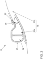
- FIG. 2 shows a schematic sectional view of a ventilation device 10.
- This view includes an air duct element 18, which in this example includes two air ducts 20a and 20b.
- Figure 2 only the exemplary positioning of these air channels 20a and 20b are shown.
- an air outflow point 22 can be seen.
- the air outflow point 22 is part of an air outflow element 24, which in this figure 2 is only shown as an example.
- Such an air outflow element 24 could also be referred to as a blade vent. It is conceivable that the air outflow element 24 has a different shape than that in Figure 2 has the shape shown.
- the arrangement of the air channels 20a, 20b and the air outflow element 24 are also shown here only as an example.
- a directional element 25 can also be seen in this exemplary embodiment.
- Such a directing element 25, as shown, can be at least partially integrated into the structure of the air outflow element 24 in such a way that components, for example, are also materially connected to this or other components. This is conceivable up to a degree of freedom such that at least one component of the directing element 25 remains separately adjustable.
- any other combination with regard to a spatial arrangement of these components of the ventilation device 10 is conceivable at this point, as long as it is ensured that at least two ventilation states, namely an indirect and a direct air flow, are made possible.
- the number of air channels in the air channel element 18 is not particularly limited. It would also be conceivable that the air duct element 18 is formed from just one air duct 20, which then supplies all of the intended air outflow points 22 of a ventilation device 10 with air.
- the air duct 20a is provided in the visible area of the side roof area 14.
- An outer area 27 of the air outflow element 24 could be designed in such a way that this outer area 27 is integrated into the appearance of the roof area 14 or cannot be visually distinguished from it.
- the air duct 20b is in the Figure 2 arranged outside the field of view and only shown using the conceivable positioning.
- such an air duct 20b could also be part of another component of the vehicle body.
- Such an air duct 20b could also be a separate component in the form of a tube, a tubular object or another geometric structure, which is designed to direct air to an intended air outflow point 22.
- a light production, not shown, could be provided, for example, using light elements in the form of light guides.
- the embodiment of Figure 2 is preferably intended for use in the roof area 14.
- a direct goal is to enable indirect ventilation through flow along a ceiling line in a selected ventilation state of the ventilation device 10.
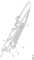
- an air outflow element 24 with an arranged directing element 25 is shown in a seat element 16.
- the straightening element 25 is shown here in the form of slats, which can be movably mounted. Due to their positioning or settings, the slats can ensure even air distribution along the ceiling line.
- electrical directivity can be implemented using an electrical device in the form of an electric motor in order to enable different ventilation styles.
- the air outflow element 24 is coupled to an air duct 20, which in turn is part of an air duct element 18.
- the air duct 20 can be supplied with air in relation to the image plane either from the left using a supply device (not shown) in the form of a rear air conditioning unit or from the right using a supply device (not shown) in the form of a front / center console air conditioning unit.
- a panel 28 is shown, which is arranged as a separating element between the air outflow element 24 with the arranged directing element 25 and a visible area of the seat element 16. In other words, this panel 28 limits the air outflow element 24 with the arranged directing element 25 in such a way that a viewer only perceives the ventilation device 10 due to the effect in the form of air provided and not visually as a separate component that is directly different from the other components of the seat element 16 visually highlights.
- the aperture 28 can also include a light element 30 in the form of a light guide, so that staging with light from the selected ventilation function is possible.
- a light element 30 in the form of a light guide, so that staging with light from the selected ventilation function is possible.
- the exemplary embodiment shown could thus enable air to be coupled into a seat structure, which could then be accompanied by a light display if a user has additionally selected this function. Integration into a back panel is therefore possible. It is also conceivable that a lighting display can be consciously switched on and off or is functionally related to a selected air conditioning program.
- FIG 4 shows a ventilation device 10 in the installed state. What can be seen is a window pane 32 in the rear of a motor vehicle and a headrest area 34 of a seat structure in the rear of this motor vehicle.
- the ventilation device 10 here comprises, for example, two air outflow elements 24 shown with respective directional elements 25, not shown in detail.
- the air outflow elements 24 with respective directional elements 25, not shown in detail are arranged in the visible area in such a way that they are clearly different from the rest of the roof area 14 visually highlight.
- the flow arrows 12 shown indicate both a possible direct and an indirect ventilation state.
- At least a portion of the window pane 32 is supplied with air in such a way that a desired effect, for example a clear view of the outside, is achieved. It is therefore also possible, for example, to implement indirect ventilation from the rear and from roof rails (not shown).
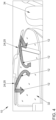
- the Figure 5a shows a sectional view of an air outflow element 24 with an arranged directing element 25 as components of a ventilation device 10, the directing element 25 being designed in the form of slats.
- the slats are divided into slats 36a in the visible area and slats 36b in the invisible area. Two slats 36a can be seen in the visible area and two slats 36b can also be seen in the invisible area. A total of four slats are therefore provided.
- the number of slats can differ in a variant not shown and can have any advantageous number of slats.
- the shape of the slats in this figure is also only to be seen as an example and any other shape of slats is also conceivable, as long as a desired direction of an air flow can be set.
- the slats 36b are therefore arranged in the background of the air outflow element 24. In the figure shown, one of these slats 36b is adjusted in such a way that it disappears at least partially or completely in a wall of the air outflow element 24, which is at least partially exposed to the air flow, and together with the wall of the air outflow element 24 has a desired effect the outflowing air has.
- the shape of the wall of the air outflow element 24 can accordingly be adapted to a shape of the slats, so that the interaction ultimately at least partially provides the desired effect on the outflowing air.
- at least one slat 36b can be adjusted in such a way that it represents an extension of an outer line of the wall or, together with the wall in which it is attached, has a common effect on outflowing air.
- Such a slat 36b can be rotatably fastened in the wall, for example with a hinge or a screw or other fastening means.
- the wall or generally the air outflow element 24 can have a recess in which the slat 36b can rest at least partially in a form-fitting manner in a foldable state.
- the opposite slat 36b is installed in a similar manner and shown in the figure.
- Different slats can be seen in front of the desired interaction of the overall concept, with a change in one slat having an effect on a resulting air flow profile, so that this state can be changed in turn by changing another slat.
- the slats 36a can at least partially take on the function of a decorative element in the visible area.
- the design of the directional element 25 can be carried out in such a way that an optical fit into a desired overall image of the interior of the motor vehicle is made possible.
- the slats 36a and 36b are in the Figure 5a adjusted so that a desired course of the flow arrow 12 shown is achieved.
- the slats 36a and 36b can be connected to the air outflow element 24, for example by means of hinges. Any other type of connection is also conceivable. It is conceivable that the slats 36a, 36b can assume a wide variety of positions in order to achieve a desired course of the flow arrow 12.
- the slats 36a, 36b can be adjustable independently of one another.
- the slats 36a, 36b can be moved at least partially coupled to one another. In other words, a deflection of any slat would then cause a movement of one or more other slats. It is also conceivable that all of the slats mentioned can be aligned in the desired manner using just one process. In particular, the interaction of two slats and the resulting arrangement relative to one another can produce a desired course of the flow arrow 12. It is also conceivable that the slats 36a, 36b are each individually adjustable and the interaction is controlled centrally, so that a resulting arrangement is ultimately established which produces a desired course of the flow arrow 12.
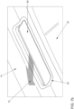
- the Figure 5b shows the air outflow element 24 with an arranged directing element 25 as components of a ventilation device 10 Figure 5a in a view from a viewer sitting in an interior area of a motor vehicle in which these components of the ventilation device are arranged.
- the slats 36a can be seen in the visible area, which at least partially take on the function of a decorative element.
- a decorative element preferably has the function of optically delimiting the ventilation device 10 to a visible interior area of the motor vehicle.
- a partial area of the air outflow element 24 can also be seen, which also takes on the function of a decorative element, at least in this partial area.
- the slats 36a can also completely take over the function of the decorative element.
- FIG 6a Another example of a directional element 25 can be seen in an installed state.
- This directing element 25 is arranged in an air outflow element 24. Both components are components of a ventilation device 10.
- the directional element 25 shown is arranged on the air outflow element 24 by means of a sliding mechanism 40, so that different ventilation states can be set either manually or electrically.
- the sliding mechanism 40 is arranged in the middle and has a straight course from the bottom right to the top left (relative to the image plane). In a variant not shown, this sliding mechanism 40 could also have an arcuate course or any other shape.
- the setting is such that a desired course of a flow arrow 12 is achieved.
- the directional element 25 includes a locking element 26, which can have the essentially shown shape of a diamond-shaped geometry.
- the sliding mechanism 40 is arranged approximately centrally on the locking element 26 in the figure.
- any other geometric shapes that allow direct or indirect air flow are also conceivable.
- the geometric shape is selected such that in a stop position, as shown in the exemplary embodiment, the locking element 26 rests at least substantially against a corresponding wall of the air outflow element 24, so that air passage is prevented at this point or at least largely avoided.
- the shape of the locking element 26 and the shape of the wall of the air outflow element 24, which is reached in a respective stop position by the locking element 26, must be at least partially matched to one another in a shape-fitting manner, so that essentially no air can pass through here.
- this is shown in that a flat side of the diamond-shaped body of the locking element 26 lies flat against the wall of the air outflow element 24, so that essentially no air escape can occur here and the flow arrow 12 can be steered in the desired direction as shown. It can be seen in particular how the air outflow element 24 and the directional element 25 together cause a desired flow pattern of an air stream to be established from within the ventilation device 10 into an interior area of a motor vehicle, not shown.
- a grip element 42 which can also only be referred to as a grip, can be seen on the directional element 25.
- This grip element 42 can be of one Users, for example, can be grasped manually in order to then move the directional element 25 into a desired position, so that a defined ventilation state is established.
- This ventilation state can then have, for example, a direct or indirect air flow.
- the directional element 25 can be actuated by means of an electrical device, for example an electric motor, with operation being possible, for example, via a climate control of an air conditioning system of a motor vehicle in which the ventilation device 10 is installed.
- the Figure 6b shows the air outflow element 24 with an arranged directing element 25 as components of a ventilation device 10 Figure 6a in a view from a viewer sitting in an interior area of a motor vehicle in which these components of the ventilation device are arranged.
- a roof area 14 and part of a window pane 32 can be seen.
- the directing element 25 is in the Figure 6b shown without a gripping element 42 and is in an upper position so that a flow arrow 12 points in the direction of the window pane 32.
- a direct ventilation state is therefore set on the window.
- the Figure 6c shows the air outflow element 24 with an arranged directing element 25 as components of a ventilation device 10 Figure 6a in a view from a viewer sitting in an interior area of a motor vehicle in which these components of the ventilation device 10 are arranged.
- a roof area 14 and part of a window pane 32 can be seen.
- the directing element 25 is in the Figure 6c shown without gripping element 42 and is in a lower position, so that a flow arrow 12 points in the direction of the roof area 14.
- An indirect ventilation state is therefore set.
- FIG 7a Another example of a directional element 25 can be seen in an installed state.
- This directing element 25 is arranged in an air outflow element 24. Both components are components of a ventilation device 10.
- the directional element 25 shown is arranged on the air outflow element 24 by means of a folding mechanism 44, so that different ventilation states can be set either manually or electrically.
- the setting is such that a desired course of a flow arrow 12 is achieved.
- the straightening element 25 comprises a locking element 26, which in the figure can essentially have the shape shown of a diamond or a diamond-shaped body or shape. This diamond-shaped shape is in the manner shown, particularly in the visible area, by means of a curved course of a front that is visible to the outside.
- the diamond-shaped locking element 26 is delimited in the visible area to the outside by a surface (outlined by a line in the figure), which bulges into the interior of a motor vehicle, not shown.
- This convex course can be adapted to the immediate surroundings of the interior of the motor vehicle in such a way that a smooth transition from the immediate surroundings to the locking element 26 occurs.
- this is indicated (relative to the image plane) in the upper left area, in that the arcuate line essentially represents an extension of an outer line from the roof area 14 shown at the top left.
- the locking element 26 is shaped in the visible area in such a way that a substantially flat transition from the roof area 14 to an outer surface of the locking element 26 is achieved.
- any other geometric shapes of the locking element 26 are also conceivable, which make it possible to enable a direct or indirect air flow.
- the aforementioned features can also occur or be taken into account with a different shape or only a slightly changed shape.
- the interaction between the course of the roof area 14 and an outer surface of the locking element 26 can be taken into account. It can be seen in particular how the air outflow element 24 and the directional element 25 together cause a desired flow pattern of an air stream to be established from within the ventilation device 10 into an interior area of a motor vehicle, not shown.
- the geometries of the two previously mentioned components are advantageously coordinated with one another.
- the folding mechanism 44 includes both a hinge 46, which is arranged centrally on the directing element 25, and an internal stand-up element 48, which is arranged on a rail element 50 in the air outflow element 24.
- the figure also only shows a possible further position for the folding mechanism 44. Any other intermediate position can be assumed between the current position shown and the further position.
- the mounting element 48 can then also assume a different position, although this position is not shown.
- the interaction between the folding mechanism 44 and the setting element 48 can take any arrangement that is made possible in accordance with the mechanical properties of the installed arrangement, so that a desired course of the flow arrow 12 is in turn achieved.
- a coupling (not shown) is conceivable. Any type of coupling element or even just one coupling element is conceivable.
- FIG. 7b shows the air outflow element 24 with an arranged directing element 25 as components of a ventilation device 10 Figure 7a in a view from a viewer sitting in an interior area of a motor vehicle in which these components of the ventilation device 10 are arranged.
- a roof area 14 and part of a window pane 32 can be seen.
- the directing element 25 is in the Figure 7b shown without gripping element 42 and is in a lower position, so that a flow arrow 12 points in the direction of the roof area 14.
- An indirect ventilation state is therefore set.
- the Figure 8 shows a schematic top view of a ventilation device 10 according to the invention.
- Two schematically illustrated air outflow elements 24 can be seen from which air flows out, the flow path in this exemplary embodiment being shown by means of dashed flow arrows 12. These air outflow elements 24 can also be referred to as static air outlets.
- a roof area 14 is shown schematically. This roof area 14 arches in relation to the image plane above two seat elements 16, which are also shown schematically.
- a directional element 25 is shown schematically on the left side above the seat element 16, which in this Figure 8 is shown as an arrow pointing downwards. This directional element 25 is in an extended state, so that the portion of the roof area 14 located immediately below curves downward.
- the installation of the directing element 25, which in this case can also be referred to as an actuator, requires that a change in shape of a roof lining occurs above this seat element 16, which is located on the left side, in order to achieve a targeted influence on the air flow by means of the To enable directing element 25 or the actuator.
- the directional element 25 can be folded out of the roof area 14 in order to bring about a desired ventilation state.
- a direct ventilation condition results, which can also be referred to as direct flow.
- a reciprocal, alternating air flow can be established or achieved on the left and right of the motor vehicle, which is reminiscent of air flows in a natural environment.
- the air outflow elements 24 on the left and right sides can, for example, be directed towards one another, so that the two competing air flows can cause air turbulence, so-called air rollers, in the center of the vehicle, which are perceived as pleasant by a passenger or generally by an occupant because their direction cannot be assigned and the speed is not constant.
Landscapes
- Engineering & Computer Science (AREA)
- Mechanical Engineering (AREA)
- Physics & Mathematics (AREA)
- Thermal Sciences (AREA)
- Power Engineering (AREA)
- Aviation & Aerospace Engineering (AREA)
- Transportation (AREA)
- Air-Conditioning For Vehicles (AREA)
Claims (5)
- Dispositif de ventilation (10) pour une zone intérieure d'un véhicule automobile, en particulier dans une zone d'une seconde rangée de sièges, comprenant au moins un élément formant conduit d'air (18), au moins un dispositif d'alimentation accouplé à une première extrémité de l'au moins un élément formant conduit d'air (18) et faisant partie d'un système de climatisation du véhicule automobile, au moins un élément de sortie d'air (24) accouplé à une seconde extrémité de l'au moins un élément formant conduit d'air (18) et conçu pour être disposé dans la zone non visible de la zone intérieure du véhicule automobile, au moins un élément de direction (25) et au moins un élément lumineux (30), dans lequel les dispositions de l'au moins un élément de direction (25) et de l'au moins un élément de sortie d'air (24) sont conçues pour amener conjointement le dispositif de ventilation (10) à pouvoir être réglé en continu entre au moins deux états de ventilation dans la zone intérieure du véhicule automobile, lesquels états de ventilation diffèrent au moins respectivement par une direction d'air sortant dirigée directement dans l'habitacle du véhicule automobile et une direction d'air sortant dirigée indirectement le long d'un ciel de toit réalisé à cet effet, par rapport à une zone de sièges du véhicule automobile, caractérisé en ce que l'au moins un élément de direction (25) est conçu pour être disposé dans une zone de toit (14) non visible de l'habitacle du véhicule automobile, dans lequel l'au moins un élément de direction (25) est conçu pour amener un changement de forme de la zone de toit (14) visible adjacente lors de l'activation de l'au moins un élément de direction (25), de sorte qu'une direction de l'air sortant de l'au moins un élément de sortie d'air (24) peut être réglée d'un état de ventilation à un autre état de ventilation.
- Dispositif de ventilation (10) selon la revendication 1, caractérisé en ce que, en fonction des au moins deux états de ventilation, une mise en scène lumineuse peut être réglée au moyen de l'au moins un élément lumineux (30).
- Dispositif de ventilation selon la revendication 1 ou la revendication 2, caractérisé en ce que l'au moins un élément formant conduit d'air (18) et l'au moins un élément de sortie d'air (24) et l'au moins un élément de direction (25) sont conçus pour être disposés dans une zone de toit (14) d'une zone intérieure du véhicule automobile.
- Dispositif de ventilation (10) selon l'une des revendications précédentes, caractérisé en ce que l'au moins un élément de direction (25) peut être réglé manuellement ou électriquement, dans lequel, dans le cas d'un réglage électrique, le dispositif de ventilation (10) est couplé à un système de climatisation programmable, de telle sorte que les au moins deux états de ventilation et la mise en scène lumineuse peuvent être réglés en fonction d'un programme activé du système de climatisation.
- Dispositif de ventilation (10) selon l'une des revendications précédentes, caractérisé en ce que le dispositif d'alimentation est accouplé sous forme d'un climatiseur avant/au centre de la console ou sous forme d'un climatiseur arrière à l'au moins un élément formant conduit d'air (18).
Applications Claiming Priority (2)
| Application Number | Priority Date | Filing Date | Title |
|---|---|---|---|
| DE102018106156.0A DE102018106156B4 (de) | 2018-03-16 | 2018-03-16 | Belüftungsvorrichtung für einen Innenbereich eines Kraftfahrzeugs, insbesondere in einem Bereich einer zweiten Sitzreihe |
| PCT/EP2019/056373 WO2019175294A1 (fr) | 2018-03-16 | 2019-03-14 | Dispositif de ventilation pour une zone intérieure d'un véhicule automobile |
Publications (2)
| Publication Number | Publication Date |
|---|---|
| EP3765320A1 EP3765320A1 (fr) | 2021-01-20 |
| EP3765320B1 true EP3765320B1 (fr) | 2024-02-28 |
Family
ID=66001165
Family Applications (1)
| Application Number | Title | Priority Date | Filing Date |
|---|---|---|---|
| EP19715001.4A Active EP3765320B1 (fr) | 2018-03-16 | 2019-03-14 | Dispositif de ventilation pour une zone intérieure d'un véhicule automobile |
Country Status (5)
| Country | Link |
|---|---|
| US (1) | US11904658B2 (fr) |
| EP (1) | EP3765320B1 (fr) |
| CN (1) | CN111770846B (fr) |
| DE (1) | DE102018106156B4 (fr) |
| WO (1) | WO2019175294A1 (fr) |
Families Citing this family (8)
| Publication number | Priority date | Publication date | Assignee | Title |
|---|---|---|---|---|
| DE102019211575A1 (de) * | 2019-08-01 | 2021-02-04 | Brose Fahrzeugteile SE & Co. Kommanditgesellschaft, Coburg | Belüftungsvorrichtung für ein Fahrzeug und Verfahren zur Belüftung |
| DE102020002486A1 (de) * | 2019-12-20 | 2021-06-24 | Gentherm Gmbh | Belüftungseinrichtung für eine Kabine eines Fahrzeugs |
| CA3120925A1 (fr) * | 2020-06-05 | 2021-12-05 | Polaris Industries Inc. | Chassis pour un vehicule hors-route |
| KR20220057695A (ko) * | 2020-10-30 | 2022-05-09 | 현대자동차주식회사 | 천장형 벤트장치 |
| DE102021110951A1 (de) | 2021-04-28 | 2022-11-03 | Kautex Textron Gmbh & Co. Kg | Ausströmungseinrichtung für ein Dachhimmelsystem und Dachhimmelsystem zur Belüftung einer Fahrgastzelle mit wenigstens einer Ausströmungseinrichtung |
| US20240059122A1 (en) * | 2022-08-18 | 2024-02-22 | Apple Inc. | Vent switching between indirect and direct modes |
| KR102527165B1 (ko) * | 2022-10-17 | 2023-04-28 | 주식회사 서연이화 | 차량용 독립 공기 조화 시트 |
| DE102023004293A1 (de) | 2023-10-26 | 2025-04-30 | Mercedes-Benz Group AG | Dachbelüftungssystem für einen Personenkraftwagen |
Family Cites Families (20)
| Publication number | Priority date | Publication date | Assignee | Title |
|---|---|---|---|---|
| DE3714223C1 (de) * | 1987-04-29 | 1988-12-22 | Fraunhofer Ges Forschung | Anordnung zur Luftfuehrung in Fahrzeugraeumen |
| JPH106745A (ja) | 1996-06-24 | 1998-01-13 | Denso Corp | 空気調和装置 |
| US6416116B1 (en) * | 2000-02-03 | 2002-07-09 | New Flyer Industries Limited | Interior structure of a mass transit vehicle |
| DE10110191A1 (de) | 2001-03-02 | 2002-09-12 | Webasto Vehicle Sys Int Gmbh | Fahrzeugdach mit einem Deckel zum Verschließen einer Dachöffnung |
| DE10239387B4 (de) | 2002-03-01 | 2011-04-07 | Volkswagen Ag | Versenkbarer Schalter |
| FR2845318B1 (fr) | 2002-10-04 | 2006-05-19 | Valeo Climatisation | Dispositif de regulation thermique pour habitacle de vehicule automobile utilisant au moins un siege |
| DE102004004387B4 (de) * | 2004-01-29 | 2006-09-14 | Daimlerchrysler Ag | Fahrzeugsitz |
| US6966829B1 (en) * | 2004-05-27 | 2005-11-22 | Lear Corporation | HVAC system for a vehicle with concealed vents |
| JP3156703U (ja) * | 2009-10-28 | 2010-01-14 | 豊和化成株式会社 | レジスタ |
| US9102215B2 (en) * | 2011-10-17 | 2015-08-11 | Ford Global Technologies, Llc | Airflow control in floor mode for vehicle with multiple seating rows |
| US20150140915A1 (en) * | 2013-11-19 | 2015-05-21 | Atieva, Inc. | Vehicle Seat Ventilation System |
| DE102014222139B4 (de) | 2014-10-30 | 2025-07-10 | Bayerische Motoren Werke Aktiengesellschaft | Kraftfahrzeug |
| JP2017030684A (ja) | 2015-08-05 | 2017-02-09 | トヨタ自動車株式会社 | 天井用空調レジスタ |
| DE102015112898A1 (de) | 2015-08-05 | 2017-02-09 | Dr. Schneider Kunststoffwerke Gmbh | Klimatisierungs- und Belüftungssystem für ein Kraftfahrzeug |
| WO2017208658A1 (fr) * | 2016-06-03 | 2017-12-07 | 株式会社デンソー | Dispositif de commande |
| US20180194194A1 (en) * | 2016-07-28 | 2018-07-12 | Faraday&Future Inc. | Air control method and system based on vehicle seat status |
| DE102018222852A1 (de) * | 2018-12-21 | 2020-06-25 | Brose Fahrzeugteile SE & Co. Kommanditgesellschaft, Coburg | Kraftfahrzeugbaugruppe mit einer Mittelkomponente |
| KR102673008B1 (ko) * | 2019-05-21 | 2024-06-05 | 현대자동차주식회사 | 루프 벤트 |
| US11760158B2 (en) * | 2019-10-07 | 2023-09-19 | Keystone Rv Company | Vent covers for recreational vehicle ductwork |
| JP2021160618A (ja) * | 2020-04-01 | 2021-10-11 | トヨタ自動車株式会社 | 車両用機器操作装置 |
-
2018
- 2018-03-16 DE DE102018106156.0A patent/DE102018106156B4/de active Active
-
2019
- 2019-03-14 EP EP19715001.4A patent/EP3765320B1/fr active Active
- 2019-03-14 CN CN201980014446.0A patent/CN111770846B/zh active Active
- 2019-03-14 WO PCT/EP2019/056373 patent/WO2019175294A1/fr not_active Ceased
-
2020
- 2020-09-16 US US17/023,325 patent/US11904658B2/en active Active
Also Published As
| Publication number | Publication date |
|---|---|
| CN111770846A (zh) | 2020-10-13 |
| WO2019175294A1 (fr) | 2019-09-19 |
| DE102018106156B4 (de) | 2026-03-12 |
| DE102018106156A1 (de) | 2019-09-19 |
| CN111770846B (zh) | 2023-11-07 |
| US11904658B2 (en) | 2024-02-20 |
| US20210001687A1 (en) | 2021-01-07 |
| EP3765320A1 (fr) | 2021-01-20 |
Similar Documents
| Publication | Publication Date | Title |
|---|---|---|
| EP3765320B1 (fr) | Dispositif de ventilation pour une zone intérieure d'un véhicule automobile | |
| DE112016003095B4 (de) | Klimatisierungs- und Belüftungssystem für ein Kraftfahrzeug | |
| DE102012021519B4 (de) | Lüftungssystem für ein Kraftfahrzeug sowie Verfahren zum Betreiben eines solchen | |
| DE102012108962B4 (de) | Passagier-Versorgungseinheit für Land-, Luft- und Wasserfahrzeuge | |
| EP3028894B1 (fr) | Dispositif de climatisation pour un vehicule automobile | |
| DE102005002062A1 (de) | Verfahren zur Regelung von Luftdüsen zur Klimatisierung eines Kraftfahrzeugs | |
| DE102016220671B4 (de) | Luftausströmer für Heizungs- und Belüftungs- oder Klimaanlagen von Kraftfahrzeugen | |
| DE202019102475U1 (de) | Fahrzeugsitzbaugruppe mit belüfteter Kühlung | |
| DE112014004376T5 (de) | Luftversorgungskomponente für einen Fahrzeugsitz | |
| EP3941767B1 (fr) | Véhicule automobile comprenant un système d'aération comprenant plusieurs buses d'aération séparées | |
| DE102014222139B4 (de) | Kraftfahrzeug | |
| DE102015101970B4 (de) | Belüftungseinrichtung für ein Fahrzeugarmaturenbrett | |
| DE102016211486B4 (de) | Kraftfahrzeug-Lüftungseinrichtung | |
| WO2012104245A1 (fr) | Diffuseur pour système de ventilation d'un véhicule | |
| DE102020128614B4 (de) | Ausströmer für einen Luftkanal eines Fahrzeugs | |
| DE102020110628B4 (de) | Luftausströmer für ein Kraftfahrzeug und Kraftfahrzeug | |
| DE102022201254A1 (de) | Armatureneinheit für ein Kraftfahrzeug | |
| EP3681758B1 (fr) | Dispositif de ventilation d'un véhicule | |
| DE102019203471B4 (de) | Kraftfahrzeug | |
| WO2021018953A1 (fr) | Dispositif d'aération pour un véhicule et procédé permettant d'aérer un compartiment passager d'un véhicule | |
| DE102023001839B3 (de) | Fahrzeugsitz | |
| DE102019203672A1 (de) | Kraftfahrzeug | |
| DE102011003433B4 (de) | Ausströmer und Belüftungssystem | |
| DE102023004293A1 (de) | Dachbelüftungssystem für einen Personenkraftwagen | |
| DE102025120556A1 (de) | Luftausströmer für eine Belüftungsvorrichtung sowie Belüftungsvorrichtung |
Legal Events
| Date | Code | Title | Description |
|---|---|---|---|
| STAA | Information on the status of an ep patent application or granted ep patent |
Free format text: STATUS: UNKNOWN |
|
| STAA | Information on the status of an ep patent application or granted ep patent |
Free format text: STATUS: THE INTERNATIONAL PUBLICATION HAS BEEN MADE |
|
| PUAI | Public reference made under article 153(3) epc to a published international application that has entered the european phase |
Free format text: ORIGINAL CODE: 0009012 |
|
| STAA | Information on the status of an ep patent application or granted ep patent |
Free format text: STATUS: REQUEST FOR EXAMINATION WAS MADE |
|
| 17P | Request for examination filed |
Effective date: 20201016 |
|
| AK | Designated contracting states |
Kind code of ref document: A1 Designated state(s): AL AT BE BG CH CY CZ DE DK EE ES FI FR GB GR HR HU IE IS IT LI LT LU LV MC MK MT NL NO PL PT RO RS SE SI SK SM TR |
|
| AX | Request for extension of the european patent |
Extension state: BA ME |
|
| RIN1 | Information on inventor provided before grant (corrected) |
Inventor name: BUDER, RICARDO Inventor name: ENKE, LUKAS Inventor name: MICHEL, TIMO Inventor name: UHLENBUSCH, OLAF |
|
| DAV | Request for validation of the european patent (deleted) | ||
| DAX | Request for extension of the european patent (deleted) | ||
| STAA | Information on the status of an ep patent application or granted ep patent |
Free format text: STATUS: EXAMINATION IS IN PROGRESS |
|
| 17Q | First examination report despatched |
Effective date: 20221011 |
|
| GRAP | Despatch of communication of intention to grant a patent |
Free format text: ORIGINAL CODE: EPIDOSNIGR1 |
|
| STAA | Information on the status of an ep patent application or granted ep patent |
Free format text: STATUS: GRANT OF PATENT IS INTENDED |
|
| RIC1 | Information provided on ipc code assigned before grant |
Ipc: B60N 2/56 20060101ALI20230922BHEP Ipc: B60H 1/00 20060101ALI20230922BHEP Ipc: B60H 1/24 20060101AFI20230922BHEP |
|
| INTG | Intention to grant announced |
Effective date: 20231010 |
|
| GRAS | Grant fee paid |
Free format text: ORIGINAL CODE: EPIDOSNIGR3 |
|
| P01 | Opt-out of the competence of the unified patent court (upc) registered |
Effective date: 20231218 |
|
| GRAA | (expected) grant |
Free format text: ORIGINAL CODE: 0009210 |
|
| STAA | Information on the status of an ep patent application or granted ep patent |
Free format text: STATUS: THE PATENT HAS BEEN GRANTED |
|
| AK | Designated contracting states |
Kind code of ref document: B1 Designated state(s): AL AT BE BG CH CY CZ DE DK EE ES FI FR GB GR HR HU IE IS IT LI LT LU LV MC MK MT NL NO PL PT RO RS SE SI SK SM TR |
|
| REG | Reference to a national code |
Ref country code: GB Ref legal event code: FG4D Free format text: NOT ENGLISH |
|
| REG | Reference to a national code |
Ref country code: CH Ref legal event code: EP |
|
| REG | Reference to a national code |
Ref country code: DE Ref legal event code: R096 Ref document number: 502019010670 Country of ref document: DE |
|
| REG | Reference to a national code |
Ref country code: IE Ref legal event code: FG4D Free format text: LANGUAGE OF EP DOCUMENT: GERMAN |
|
| REG | Reference to a national code |
Ref country code: LT Ref legal event code: MG9D |
|
| PG25 | Lapsed in a contracting state [announced via postgrant information from national office to epo] |
Ref country code: IS Free format text: LAPSE BECAUSE OF FAILURE TO SUBMIT A TRANSLATION OF THE DESCRIPTION OR TO PAY THE FEE WITHIN THE PRESCRIBED TIME-LIMIT Effective date: 20240628 |
|
| REG | Reference to a national code |
Ref country code: NL Ref legal event code: MP Effective date: 20240228 |
|
| PG25 | Lapsed in a contracting state [announced via postgrant information from national office to epo] |
Ref country code: LT Free format text: LAPSE BECAUSE OF FAILURE TO SUBMIT A TRANSLATION OF THE DESCRIPTION OR TO PAY THE FEE WITHIN THE PRESCRIBED TIME-LIMIT Effective date: 20240228 |
|
| PG25 | Lapsed in a contracting state [announced via postgrant information from national office to epo] |
Ref country code: GR Free format text: LAPSE BECAUSE OF FAILURE TO SUBMIT A TRANSLATION OF THE DESCRIPTION OR TO PAY THE FEE WITHIN THE PRESCRIBED TIME-LIMIT Effective date: 20240529 |
|
| PG25 | Lapsed in a contracting state [announced via postgrant information from national office to epo] |
Ref country code: NL Free format text: LAPSE BECAUSE OF FAILURE TO SUBMIT A TRANSLATION OF THE DESCRIPTION OR TO PAY THE FEE WITHIN THE PRESCRIBED TIME-LIMIT Effective date: 20240228 Ref country code: HR Free format text: LAPSE BECAUSE OF FAILURE TO SUBMIT A TRANSLATION OF THE DESCRIPTION OR TO PAY THE FEE WITHIN THE PRESCRIBED TIME-LIMIT Effective date: 20240228 Ref country code: RS Free format text: LAPSE BECAUSE OF FAILURE TO SUBMIT A TRANSLATION OF THE DESCRIPTION OR TO PAY THE FEE WITHIN THE PRESCRIBED TIME-LIMIT Effective date: 20240528 |
|
| PG25 | Lapsed in a contracting state [announced via postgrant information from national office to epo] |
Ref country code: ES Free format text: LAPSE BECAUSE OF FAILURE TO SUBMIT A TRANSLATION OF THE DESCRIPTION OR TO PAY THE FEE WITHIN THE PRESCRIBED TIME-LIMIT Effective date: 20240228 |
|
| PG25 | Lapsed in a contracting state [announced via postgrant information from national office to epo] |
Ref country code: RS Free format text: LAPSE BECAUSE OF FAILURE TO SUBMIT A TRANSLATION OF THE DESCRIPTION OR TO PAY THE FEE WITHIN THE PRESCRIBED TIME-LIMIT Effective date: 20240528 Ref country code: NO Free format text: LAPSE BECAUSE OF FAILURE TO SUBMIT A TRANSLATION OF THE DESCRIPTION OR TO PAY THE FEE WITHIN THE PRESCRIBED TIME-LIMIT Effective date: 20240528 Ref country code: NL Free format text: LAPSE BECAUSE OF FAILURE TO SUBMIT A TRANSLATION OF THE DESCRIPTION OR TO PAY THE FEE WITHIN THE PRESCRIBED TIME-LIMIT Effective date: 20240228 Ref country code: LT Free format text: LAPSE BECAUSE OF FAILURE TO SUBMIT A TRANSLATION OF THE DESCRIPTION OR TO PAY THE FEE WITHIN THE PRESCRIBED TIME-LIMIT Effective date: 20240228 Ref country code: IS Free format text: LAPSE BECAUSE OF FAILURE TO SUBMIT A TRANSLATION OF THE DESCRIPTION OR TO PAY THE FEE WITHIN THE PRESCRIBED TIME-LIMIT Effective date: 20240628 Ref country code: HR Free format text: LAPSE BECAUSE OF FAILURE TO SUBMIT A TRANSLATION OF THE DESCRIPTION OR TO PAY THE FEE WITHIN THE PRESCRIBED TIME-LIMIT Effective date: 20240228 Ref country code: GR Free format text: LAPSE BECAUSE OF FAILURE TO SUBMIT A TRANSLATION OF THE DESCRIPTION OR TO PAY THE FEE WITHIN THE PRESCRIBED TIME-LIMIT Effective date: 20240529 Ref country code: FI Free format text: LAPSE BECAUSE OF FAILURE TO SUBMIT A TRANSLATION OF THE DESCRIPTION OR TO PAY THE FEE WITHIN THE PRESCRIBED TIME-LIMIT Effective date: 20240228 Ref country code: ES Free format text: LAPSE BECAUSE OF FAILURE TO SUBMIT A TRANSLATION OF THE DESCRIPTION OR TO PAY THE FEE WITHIN THE PRESCRIBED TIME-LIMIT Effective date: 20240228 Ref country code: BG Free format text: LAPSE BECAUSE OF FAILURE TO SUBMIT A TRANSLATION OF THE DESCRIPTION OR TO PAY THE FEE WITHIN THE PRESCRIBED TIME-LIMIT Effective date: 20240228 |
|
| PG25 | Lapsed in a contracting state [announced via postgrant information from national office to epo] |
Ref country code: PT Free format text: LAPSE BECAUSE OF FAILURE TO SUBMIT A TRANSLATION OF THE DESCRIPTION OR TO PAY THE FEE WITHIN THE PRESCRIBED TIME-LIMIT Effective date: 20240628 Ref country code: PL Free format text: LAPSE BECAUSE OF FAILURE TO SUBMIT A TRANSLATION OF THE DESCRIPTION OR TO PAY THE FEE WITHIN THE PRESCRIBED TIME-LIMIT Effective date: 20240228 |
|
| PG25 | Lapsed in a contracting state [announced via postgrant information from national office to epo] |
Ref country code: SE Free format text: LAPSE BECAUSE OF FAILURE TO SUBMIT A TRANSLATION OF THE DESCRIPTION OR TO PAY THE FEE WITHIN THE PRESCRIBED TIME-LIMIT Effective date: 20240228 Ref country code: PT Free format text: LAPSE BECAUSE OF FAILURE TO SUBMIT A TRANSLATION OF THE DESCRIPTION OR TO PAY THE FEE WITHIN THE PRESCRIBED TIME-LIMIT Effective date: 20240628 Ref country code: PL Free format text: LAPSE BECAUSE OF FAILURE TO SUBMIT A TRANSLATION OF THE DESCRIPTION OR TO PAY THE FEE WITHIN THE PRESCRIBED TIME-LIMIT Effective date: 20240228 Ref country code: LV Free format text: LAPSE BECAUSE OF FAILURE TO SUBMIT A TRANSLATION OF THE DESCRIPTION OR TO PAY THE FEE WITHIN THE PRESCRIBED TIME-LIMIT Effective date: 20240228 |
|
| PG25 | Lapsed in a contracting state [announced via postgrant information from national office to epo] |
Ref country code: DK Free format text: LAPSE BECAUSE OF FAILURE TO SUBMIT A TRANSLATION OF THE DESCRIPTION OR TO PAY THE FEE WITHIN THE PRESCRIBED TIME-LIMIT Effective date: 20240228 |
|
| PG25 | Lapsed in a contracting state [announced via postgrant information from national office to epo] |
Ref country code: SM Free format text: LAPSE BECAUSE OF FAILURE TO SUBMIT A TRANSLATION OF THE DESCRIPTION OR TO PAY THE FEE WITHIN THE PRESCRIBED TIME-LIMIT Effective date: 20240228 |
|
| PG25 | Lapsed in a contracting state [announced via postgrant information from national office to epo] |
Ref country code: CZ Free format text: LAPSE BECAUSE OF FAILURE TO SUBMIT A TRANSLATION OF THE DESCRIPTION OR TO PAY THE FEE WITHIN THE PRESCRIBED TIME-LIMIT Effective date: 20240228 Ref country code: EE Free format text: LAPSE BECAUSE OF FAILURE TO SUBMIT A TRANSLATION OF THE DESCRIPTION OR TO PAY THE FEE WITHIN THE PRESCRIBED TIME-LIMIT Effective date: 20240228 |
|
| PG25 | Lapsed in a contracting state [announced via postgrant information from national office to epo] |
Ref country code: SK Free format text: LAPSE BECAUSE OF FAILURE TO SUBMIT A TRANSLATION OF THE DESCRIPTION OR TO PAY THE FEE WITHIN THE PRESCRIBED TIME-LIMIT Effective date: 20240228 |
|
| PG25 | Lapsed in a contracting state [announced via postgrant information from national office to epo] |
Ref country code: SM Free format text: LAPSE BECAUSE OF FAILURE TO SUBMIT A TRANSLATION OF THE DESCRIPTION OR TO PAY THE FEE WITHIN THE PRESCRIBED TIME-LIMIT Effective date: 20240228 Ref country code: SK Free format text: LAPSE BECAUSE OF FAILURE TO SUBMIT A TRANSLATION OF THE DESCRIPTION OR TO PAY THE FEE WITHIN THE PRESCRIBED TIME-LIMIT Effective date: 20240228 Ref country code: RO Free format text: LAPSE BECAUSE OF FAILURE TO SUBMIT A TRANSLATION OF THE DESCRIPTION OR TO PAY THE FEE WITHIN THE PRESCRIBED TIME-LIMIT Effective date: 20240228 Ref country code: EE Free format text: LAPSE BECAUSE OF FAILURE TO SUBMIT A TRANSLATION OF THE DESCRIPTION OR TO PAY THE FEE WITHIN THE PRESCRIBED TIME-LIMIT Effective date: 20240228 Ref country code: DK Free format text: LAPSE BECAUSE OF FAILURE TO SUBMIT A TRANSLATION OF THE DESCRIPTION OR TO PAY THE FEE WITHIN THE PRESCRIBED TIME-LIMIT Effective date: 20240228 Ref country code: CZ Free format text: LAPSE BECAUSE OF FAILURE TO SUBMIT A TRANSLATION OF THE DESCRIPTION OR TO PAY THE FEE WITHIN THE PRESCRIBED TIME-LIMIT Effective date: 20240228 |
|
| REG | Reference to a national code |
Ref country code: CH Ref legal event code: PL |
|
| PG25 | Lapsed in a contracting state [announced via postgrant information from national office to epo] |
Ref country code: LU Free format text: LAPSE BECAUSE OF NON-PAYMENT OF DUE FEES Effective date: 20240314 |
|
| PG25 | Lapsed in a contracting state [announced via postgrant information from national office to epo] |
Ref country code: MC Free format text: LAPSE BECAUSE OF FAILURE TO SUBMIT A TRANSLATION OF THE DESCRIPTION OR TO PAY THE FEE WITHIN THE PRESCRIBED TIME-LIMIT Effective date: 20240228 |
|
| PG25 | Lapsed in a contracting state [announced via postgrant information from national office to epo] |
Ref country code: MC Free format text: LAPSE BECAUSE OF FAILURE TO SUBMIT A TRANSLATION OF THE DESCRIPTION OR TO PAY THE FEE WITHIN THE PRESCRIBED TIME-LIMIT Effective date: 20240228 Ref country code: LU Free format text: LAPSE BECAUSE OF NON-PAYMENT OF DUE FEES Effective date: 20240314 |
|
| REG | Reference to a national code |
Ref country code: DE Ref legal event code: R097 Ref document number: 502019010670 Country of ref document: DE |
|
| PG25 | Lapsed in a contracting state [announced via postgrant information from national office to epo] |
Ref country code: IT Free format text: LAPSE BECAUSE OF FAILURE TO SUBMIT A TRANSLATION OF THE DESCRIPTION OR TO PAY THE FEE WITHIN THE PRESCRIBED TIME-LIMIT Effective date: 20240228 |
|
| REG | Reference to a national code |
Ref country code: BE Ref legal event code: MM Effective date: 20240331 |
|
| PG25 | Lapsed in a contracting state [announced via postgrant information from national office to epo] |
Ref country code: IT Free format text: LAPSE BECAUSE OF FAILURE TO SUBMIT A TRANSLATION OF THE DESCRIPTION OR TO PAY THE FEE WITHIN THE PRESCRIBED TIME-LIMIT Effective date: 20240228 |
|
| PLBE | No opposition filed within time limit |
Free format text: ORIGINAL CODE: 0009261 |
|
| STAA | Information on the status of an ep patent application or granted ep patent |
Free format text: STATUS: NO OPPOSITION FILED WITHIN TIME LIMIT |
|
| REG | Reference to a national code |
Ref country code: DE Ref legal event code: R082 Ref document number: 502019010670 Country of ref document: DE |
|
| PG25 | Lapsed in a contracting state [announced via postgrant information from national office to epo] |
Ref country code: BE Free format text: LAPSE BECAUSE OF NON-PAYMENT OF DUE FEES Effective date: 20240331 |
|
| PG25 | Lapsed in a contracting state [announced via postgrant information from national office to epo] |
Ref country code: IE Free format text: LAPSE BECAUSE OF NON-PAYMENT OF DUE FEES Effective date: 20240314 |
|
| PG25 | Lapsed in a contracting state [announced via postgrant information from national office to epo] |
Ref country code: IE Free format text: LAPSE BECAUSE OF NON-PAYMENT OF DUE FEES Effective date: 20240314 Ref country code: BE Free format text: LAPSE BECAUSE OF NON-PAYMENT OF DUE FEES Effective date: 20240331 Ref country code: CH Free format text: LAPSE BECAUSE OF NON-PAYMENT OF DUE FEES Effective date: 20240331 |
|
| 26N | No opposition filed |
Effective date: 20241129 |
|
| PG25 | Lapsed in a contracting state [announced via postgrant information from national office to epo] |
Ref country code: SI Free format text: LAPSE BECAUSE OF FAILURE TO SUBMIT A TRANSLATION OF THE DESCRIPTION OR TO PAY THE FEE WITHIN THE PRESCRIBED TIME-LIMIT Effective date: 20240228 |
|
| REG | Reference to a national code |
Ref country code: AT Ref legal event code: MM01 Ref document number: 1660930 Country of ref document: AT Kind code of ref document: T Effective date: 20240314 |
|
| PG25 | Lapsed in a contracting state [announced via postgrant information from national office to epo] |
Ref country code: AT Free format text: LAPSE BECAUSE OF NON-PAYMENT OF DUE FEES Effective date: 20240314 |
|
| PG25 | Lapsed in a contracting state [announced via postgrant information from national office to epo] |
Ref country code: CY Free format text: LAPSE BECAUSE OF FAILURE TO SUBMIT A TRANSLATION OF THE DESCRIPTION OR TO PAY THE FEE WITHIN THE PRESCRIBED TIME-LIMIT; INVALID AB INITIO Effective date: 20190314 |
|
| PG25 | Lapsed in a contracting state [announced via postgrant information from national office to epo] |
Ref country code: HU Free format text: LAPSE BECAUSE OF FAILURE TO SUBMIT A TRANSLATION OF THE DESCRIPTION OR TO PAY THE FEE WITHIN THE PRESCRIBED TIME-LIMIT; INVALID AB INITIO Effective date: 20190314 |
|
| PG25 | Lapsed in a contracting state [announced via postgrant information from national office to epo] |
Ref country code: TR Free format text: LAPSE BECAUSE OF FAILURE TO SUBMIT A TRANSLATION OF THE DESCRIPTION OR TO PAY THE FEE WITHIN THE PRESCRIBED TIME-LIMIT Effective date: 20240228 |
|
| PGFP | Annual fee paid to national office [announced via postgrant information from national office to epo] |
Ref country code: GB Payment date: 20260323 Year of fee payment: 8 |
|
| PGFP | Annual fee paid to national office [announced via postgrant information from national office to epo] |
Ref country code: DE Payment date: 20260331 Year of fee payment: 8 |
|
| PGFP | Annual fee paid to national office [announced via postgrant information from national office to epo] |
Ref country code: FR Payment date: 20260323 Year of fee payment: 8 |