EP3766351B1 - Dispositif de portionnement de pâte - Google Patents
Dispositif de portionnement de pâte Download PDFInfo
- Publication number
- EP3766351B1 EP3766351B1 EP20183576.6A EP20183576A EP3766351B1 EP 3766351 B1 EP3766351 B1 EP 3766351B1 EP 20183576 A EP20183576 A EP 20183576A EP 3766351 B1 EP3766351 B1 EP 3766351B1
- Authority
- EP
- European Patent Office
- Prior art keywords
- portioning
- measuring
- dough
- chamber housing
- chamber
- Prior art date
- Legal status (The legal status is an assumption and is not a legal conclusion. Google has not performed a legal analysis and makes no representation as to the accuracy of the status listed.)
- Active
Links
Images



Classifications
-
- A—HUMAN NECESSITIES
- A21—BAKING; EDIBLE DOUGHS
- A21C—MACHINES OR EQUIPMENT FOR MAKING OR PROCESSING DOUGHS; HANDLING BAKED ARTICLES MADE FROM DOUGH
- A21C5/00—Dough-dividing machines
- A21C5/02—Dough-dividing machines with division boxes and ejection plungers
-
- A—HUMAN NECESSITIES
- A21—BAKING; EDIBLE DOUGHS
- A21C—MACHINES OR EQUIPMENT FOR MAKING OR PROCESSING DOUGHS; HANDLING BAKED ARTICLES MADE FROM DOUGH
- A21C5/00—Dough-dividing machines
- A21C5/02—Dough-dividing machines with division boxes and ejection plungers
- A21C5/04—Dough-dividing machines with division boxes and ejection plungers with division boxes in a revolving body with radially-working pistons
Definitions
- German utility model application DE 20 2019 103 931.0 The content of the German utility model application DE 20 2019 103 931.0 is incorporated herein by reference.
- the invention relates to a particularly multi-row dough portioning device with at least one portioning chamber for specifying a portioned amount of dough and at least one measuring piston, which can be displaced in the portioning chamber.
- Such dough portioning devices are known from DE 10 2013 221 230 A1 , from the EP 2 071 955 B1 , from the EP 3 298 900 A , from the DE 196 40 176 A1 and from the EP 0 643 914 A1 .
- the GB659,147 describes a dough divider.
- the U.S. 3,785,623 describes a dough portioner.
- the EP 0 213 582 A2 and the EP 0 494 367 A1 disclose designs of dough dividers.
- the DE 2 244 469 A discloses an apparatus for portioning dough.
- the EP 2 353 390 A2 discloses a dividing chamber support for a dough divider.
- the JP S57 56486 U reveals a latch.
- this object is achieved by a dough portioning device having the features specified in claim 1 .
- an anti-twist bar that can be removed from the chamber housing perpendicular to the displacement direction of the measuring pistons creates the possibility of mounting the anti-rotation bar on the chamber housing without tools and accordingly also removing it from the chamber housing without tools. This avoids problems associated with installing the anti-rotation bar that requires a tool are.
- the anti-rotation bar can be removed perpendicularly to the displacement direction of the measuring pistons from the chamber housing, which is in particular designed to be pivotable. The removal direction is directed away from the protruding section of the chamber housing, so that this protruding section does not interfere.
- a circumferential section via which the measuring pistons interact with the anti-rotation bar to prevent rotation can also be directed away from the protruding section.
- a diameter of the portioning chambers or a shaft height of a housing of a portioning module can be greater than 50 mm and can be 65 mm, for example.
- a portioning cylinder according to claim 5 has proven to be particularly suitable.
- a length of the portioning chambers can be specified, in particular adjustable, by a relative displacement of the measuring unit to the base body.
- a countersunk arrangement of mounting elements according to claim 7 for mounting the measuring unit on the base body ensures that the mounting elements do not interfere with the expansion of the anti-twist strip.
- a dough processing system of which the drawing shows a portioning module 1 of a six-row dough portioning device in the embodiment shown, is used for portioning and kneading dough, for example in the production of rolls.
- Corresponding dough processing systems are known from DE 10 2013 221 230 A1 , the EP 2 071 955 B1 , the EP 3 298 900 A , the DE 196 40 176 A1 and the EP 0 643 914 A1 .
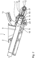
- Dough is fed into a feed funnel 2 (cf. e.g 1 ) fillable.
- a bottom exit opening 3 (cf. 2 ) of the feed funnel 2 is connected to a conveying chamber 4 in which a conveying piston, not shown in the drawing, runs.
- the conveyor piston represents a dough feed device of the dough processing system.
- the dough processing system has a total of several rows and has a corresponding number of portioning chambers 5 for presetting a portioned amount of dough.
- a total of six are perpendicular to the plane of the drawing, for example 1 and 2 such portioning chambers 5 arranged next to one another.
- a diameter of the portioning chambers 5 or a shaft height H of the conveying space 4 is greater than 50 mm and can be 65 mm, for example.
- Shell walls 6 of the portioning chambers 5 are formed in a pivotable chamber housing 6a of a portioning cylinder 7 which, driven by a pivot drive not shown in detail, can be pivoted about a pivot axis which is perpendicular to the plane of the drawing 1 and 2 is arranged.
- the portioning cylinder 7 is also referred to as a rotary slide. In the 1 and 3 the portioning cylinder 7 is in a measuring pivoted position in which the portioning chambers 5 are aligned with the conveying chamber 4 and are in dough conveying connection with it.
- a measuring piston 8 is arranged in each of the portioning chambers 5 .
- the respective measuring piston 8 has an oval piston cross section. Alternatively, a piston cross section of the measuring piston can also be circular.
- the respective measuring piston 8 is in the portioning chamber 5 assigned to it between a retracted measuring position, which is in the 2 is shown, and a pushed-out ejection position hubverlagerbar. In the ejection position, a front piston surface of the respective measuring piston 8 is aligned with a pivoting guide wall 9 which at the same time forms a transition between the portioning cylinder 7 and a housing 10 of the portioning module 1 .
- the measuring flasks 8 can be made of plastic.
- a drive unit 11 which has a control component designed as a control roller 12 , is used to move the measuring piston 8 from the measuring position to the ejection position.
- the dough portioning device is designed in such a way that a displacement of the measuring pistons 8 from the ejection position into the measuring position takes place exclusively via a conveying pressure exerted on the measuring pistons 8 by the dough fed in.
- the control roller 12 has a longitudinal extension perpendicular to the plane of the 1 and 2 .
- the control roller 12 is connected to all measuring pistons 8 in order to transmit a tensile force from the control roller 12 to the measuring pistons 8 .
- the drive unit 11 also includes at least one control cam 13 which interacts with the control roller 12 .
- the cam 13 is made in two parts and interacts with opposite free axial control sections of the control roller 12 .
- the respective measuring piston 8 is guided via two axially spaced guide surfaces 14, 15 in the associated portioning chambers 5, namely on the casing walls 6. Instead of several guide surfaces for guiding in the portioning chamber 5, the respective measuring piston 8 can also have exactly one guide surface.
- the lifting movement of the measuring piston between the measuring position and the ejection position is guided via a two-part guide fork 16.
- the control roller 12 runs in the guide fork 16. In the measuring position of the measuring piston 8, the control roller 12 is located, as in FIG 2 shown near a free end of the guide fork 16.
- the dough pressure which is generated via the dough conveyance from the conveying chamber 4 into the portioning chamber 5, ensures that the measuring pistons 8, which are initially in the ejection position, move into the measuring position via the dough pressure, for example 2 be transferred.
- the respective measuring piston 8 is in thrust connection with the control roller 12 via a plunger surface 17 .
- This push connection ensures that the control roller 12 in the 2 shown measuring position in the area of the free end of the guide fork 16 is shifted.
- the tensile connection between the control roller 12 and all measuring pistons 8 ensures that all measuring pistons 8 assume exactly the same position as far as the relative positioning within the respective portioning chamber 5 is concerned, regardless of how easy or difficult the guidance via the guide surfaces 14, 15 of the individual volumetric flasks 8 takes place.
- the measuring pistons 8 are then transferred from the measuring position, driven by the drive unit 11 with the control roller 12 and the control cam 13, to the ejection position.
- the portion of dough that has been in the portioning chamber 5 up to that point is transferred to a downstream processing unit of the dough processing system.
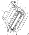
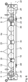
- An anti-twist bar 18 (cf. Figures 3 to 7 ) is detachably mounted on a housing rear wall 19 on the chamber housing 6a.
- the anti-rotation bar 18 acts with peripheral recesses 20 in the respective Measuring pistons to prevent the measuring pistons 8 from twisting together. This prevents these measuring pistons from twisting about their longitudinal axis in an undesired manner. Sections of the anti-rotation bar 18 bear against the peripheral recesses 20 of the measuring pistons 8 .
- a cylinder-side part of the chamber housing 6a which is in the Figures 5 to 7 is not shown, has a protruding section 21 (cf. 3 ), which protrudes backwards, ie away from the portioning chambers 5, beyond the rear wall 19 of the housing.
- the anti-rotation bar 18 is mounted on the chamber housing 6a in such a way that, when it is released, it moves in a removal direction 22 (cf. 3 ) perpendicular to the displacement direction 23 (cf. 2 ) the measuring piston 8 can be removed from the chamber housing 6a.
- This removal direction 22 is directed away from the projecting section 21 of the chamber housing 6a.
- the anti-rotation bar 18 is mounted on the chamber housing 6a via two locking units 24 that can be actuated without tools. Alternatively, a different number of such locking units can also be provided for mounting the anti-rotation bar 18 .
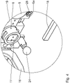
- the respective locking unit 24 is designed as a bolt 25 fixed to the housing (cf. 7 ) performed, which engages in a recess 26 in the anti-rotation strip 18.
- the bolt 25 is biased in a locking position by a spring of the locking unit 24 that is not visible in the drawing 7 is shown.
- a section of the respective portioning chamber 5 is delimited by a measuring unit 27 in the form of a strip.
- the measuring unit 27 is on a main body 28 of the chamber housing 6a mounted.
- a length of the portioning chambers 5 can be specified by an adjustable relative portioning of the measuring unit 27 to the base body 28 .
- the measuring unit 27 is flush with the rear wall 19 of the housing.
- the anti-rotation bar 18 can be detached from the chamber housing 6a by pulling the respective actuating heads of the locking units 24 so that the bolts 25 move out of the recesses 26 in the anti-rotation bar 18 against their pretensioning spring force.
- the anti-rotation strip 18 can be removed from the chamber housing 6a in the disengaged position of the two bolts 25 in the removal direction 22 .
- Retaining chambers 30, which are each mounted on the housing rear wall 19 of the chamber housing 6a, secure the anti-rotation bar 18 in the mounted position against unwanted displacement parallel to the stroke displacement of the measuring piston 8.
Landscapes
- Life Sciences & Earth Sciences (AREA)
- Engineering & Computer Science (AREA)
- Food Science & Technology (AREA)
- Manufacturing And Processing Devices For Dough (AREA)
Claims (9)
- Dispositif de portionnement de pâte sur plusieurs rangées- avec un boîtier de chambre (6a),- avec une pluralité de chambres de portionnement (5) pour prédéfinir une quantité de pâte portionnée,- avec une pluralité de fioles de mesure (8) qui peuvent être déplacées dans les chambres de portionnement (5) respectivement le long d'une direction de déplacement (23),-- entre une position de mesure rétractée, dans laquelle la fiole de mesure (8) respective prédéfinit un volume de portionnement prédéfini dans la chambre de portionnement (5) respective,-- et une position d'éjection,- avec une barrette anti-rotation (18) qui est montée de manière amovible sur une paroi arrière de boîtier (19) sur le boîtier de chambre (6a) et qui coopère avec un évidement périphérique (20) dans les fioles de mesure (8) pour empêcher la rotation des fioles de mesure (8),- dans lequel la barrette anti-rotation (18) est montée sur le boîtier de chambre (6a) de telle sorte qu'elle peut être retirée du boîtier de chambre (6a) lors du desserrage dans une direction de démontage (22) perpendiculaire à la direction de déplacement (23) des fioles de mesure (8),caractérisé en ce que le boîtier de chambre (6a) comprend une partie en saillie (21) qui dépasse de la paroi arrière de boîtier (19),- dans lequel la barrette anti-rotation (18) est conçue de manière à pouvoir être montée sans outil sur le boîtier de chambre (6a) et à pouvoir être retirée sans outil du boîtier de chambre (6a).
- Dispositif de portionnement de pâte selon la revendication 1, caractérisé en ce que la barrette anti-rotation (18) est montée sur le boîtier de chambre (6a) par l'intermédiaire d'au moins une unité de verrouillage (24) pouvant être actionnée sans outil.
- Dispositif de portionnement de pâte selon la revendication 2, caractérisé en ce que l'unité de verrouillage (24) présente un boulon (25) guidé de manière solidaire du boîtier, qui s'engage dans un évidement (26) dans la barrette anti-rotation (18).
- Dispositif de portionnement de pâte selon la revendication 3, caractérisé en ce que le boulon (25) est réalisé sous forme de boulon à ressort qui est précontraint dans une position de verrouillage.
- Dispositif de portionnement de pâte selon l'une quelconque des revendications 1 à 4, caractérisé en ce que le boîtier de chambre (6a) est réalisé en tant que partie d'un cylindre de portionnement (7) qui peut pivoter.- entre une position de mesure pivotante, dans laquelle la fiole de mesure (8) prédéfinit le volume de portionnement prédéfini dans la position de mesure,- et une position pivotée d'éjection, dans laquelle la fiole de mesure (8) peut être déplacée dans la position d'éjection pour transférer une portion de pâte à une unité de traitement située en aval.
- Dispositif de portionnement de pâte selon l'une quelconque des revendications 1 à 5, caractérisé en ce qu'au moins une section de la chambre de portionnement (5) respective est délimitée par une unité de mesure (27) pour prédéfinir une longueur de la chambre de portionnement (5), qui est montée sur un corps de base (28) du boîtier de chambre (6a).
- Dispositif de portionnement de pâte selon la revendication 6, caractérisé en ce que l'unité de mesure (27) est alignée avec la paroi arrière (19) du boîtier, dans lequel des éléments de montage (29) pour le montage de l'unité de mesure (27) sur le corps de base (28) sont disposés en retrait dans l'unité de mesure (27) pour prédéfinir une longueur de la chambre de portionnement (5).
- Dispositif de portionnement de pâte selon l'une quelconque des revendications 1 à 7, caractérisé par un modèle à plusieurs rangées avec une pluralité correspondante de chambres de portionnement (5) et de fioles de mesure (8).
- Installation de traitement de pâte comprenant un dispositif de portionnement de pâte selon l'une quelconque des revendications 1 à 8.
Applications Claiming Priority (1)
| Application Number | Priority Date | Filing Date | Title |
|---|---|---|---|
| DE202019103931.0U DE202019103931U1 (de) | 2019-07-17 | 2019-07-17 | Teigportioniervorrichtung |
Publications (2)
| Publication Number | Publication Date |
|---|---|
| EP3766351A1 EP3766351A1 (fr) | 2021-01-20 |
| EP3766351B1 true EP3766351B1 (fr) | 2022-08-24 |
Family
ID=71452072
Family Applications (1)
| Application Number | Title | Priority Date | Filing Date |
|---|---|---|---|
| EP20183576.6A Active EP3766351B1 (fr) | 2019-07-17 | 2020-07-02 | Dispositif de portionnement de pâte |
Country Status (5)
| Country | Link |
|---|---|
| US (1) | US11889838B2 (fr) |
| EP (1) | EP3766351B1 (fr) |
| DE (1) | DE202019103931U1 (fr) |
| ES (1) | ES2928707T3 (fr) |
| HU (1) | HUE060666T2 (fr) |
Citations (1)
| Publication number | Priority date | Publication date | Assignee | Title |
|---|---|---|---|---|
| EP0643914B1 (fr) * | 1993-09-21 | 1999-01-07 | Werner & Pfleiderer Lebensmitteltechnik GmbH | Diviseur de pâte avec chambre de dosage |
Family Cites Families (11)
| Publication number | Priority date | Publication date | Assignee | Title |
|---|---|---|---|---|
| GB659147A (en) * | 1948-12-28 | 1951-10-17 | Baker Perkins Ltd | Improvements in and relating to dough dividers |
| AT332822B (de) * | 1971-09-13 | 1976-10-25 | Koenig Helmut | Vorrichtung zum portionieren von teig |
| JPS5756486A (en) | 1980-08-11 | 1982-04-05 | Fujisawa Pharmaceut Co Ltd | Novel cephem compound or its salt, their preparation and prophylactic or remedy for microbism containing the same as active ingredient |
| JPS5831513Y2 (ja) * | 1980-09-20 | 1983-07-12 | 株式会社 藤沢製作所 | 分割機 |
| DE3530724C1 (de) | 1985-08-28 | 1986-07-03 | Werner & Pfleiderer, 7000 Stuttgart | Teigteilmaschine |
| DE4100243C2 (de) * | 1991-01-07 | 1993-12-09 | Werner & Pfleiderer | Teigteilmaschine |
| DE19640176A1 (de) | 1996-09-28 | 1998-04-02 | Werner & Pfleiderer Lebensmitt | Teigteil-Maschine |
| DE102007062386A1 (de) | 2007-12-22 | 2009-06-25 | Werner & Pfleiderer Lebensmitteltechnik Gmbh | Teigbearbeitungsanlage |
| DE102010007307A1 (de) * | 2010-02-08 | 2011-08-11 | Fortuna Maschinenbau Holding AG, 96231 | Teilkammerträger für eine Teigteilmaschine |
| DE102013221230B4 (de) | 2013-10-18 | 2017-10-05 | Werner & Pfleiderer Lebensmitteltechnik Gmbh | Drehschieber-Baugruppe für eine Teig-Portioniervorrichtung |
| DE102016218485A1 (de) | 2016-09-27 | 2018-03-29 | Werner & Pfleiderer Lebensmitteltechnik Gmbh | Kammertrommel für eine Teig-Wirkvorrichtung |
-
2019
- 2019-07-17 DE DE202019103931.0U patent/DE202019103931U1/de active Active
-
2020
- 2020-07-02 ES ES20183576T patent/ES2928707T3/es active Active
- 2020-07-02 EP EP20183576.6A patent/EP3766351B1/fr active Active
- 2020-07-02 HU HUE20183576A patent/HUE060666T2/hu unknown
- 2020-07-15 US US16/947,009 patent/US11889838B2/en active Active
Patent Citations (1)
| Publication number | Priority date | Publication date | Assignee | Title |
|---|---|---|---|---|
| EP0643914B1 (fr) * | 1993-09-21 | 1999-01-07 | Werner & Pfleiderer Lebensmitteltechnik GmbH | Diviseur de pâte avec chambre de dosage |
Also Published As
| Publication number | Publication date |
|---|---|
| US20210015110A1 (en) | 2021-01-21 |
| US11889838B2 (en) | 2024-02-06 |
| ES2928707T3 (es) | 2022-11-22 |
| DE202019103931U1 (de) | 2020-10-20 |
| EP3766351A1 (fr) | 2021-01-20 |
| HUE060666T2 (hu) | 2023-04-28 |
Similar Documents
| Publication | Publication Date | Title |
|---|---|---|
| EP3626133A1 (fr) | Dispositif de présentation des marchandises | |
| EP2848558B1 (fr) | Système d'ajustage | |
| DE1930151B2 (de) | Auslassvorrichtung an einer bolzenzufuehrungsvorrichtung | |
| DE4012736A1 (de) | Biegevorrichtung fuer rohrleitungen | |
| DE19700723C2 (de) | Extruder | |
| DE20312833U1 (de) | Schmiergerät und ein solches aufweisende Abschmiereinrichtung | |
| EP2049270A1 (fr) | Pistolet à cartouche | |
| EP1557387B1 (fr) | Organe de transport avec une chaine à maillons et des clips | |
| EP3581029B1 (fr) | Dispositif de division en portions de pâte | |
| EP3766351A1 (fr) | Dispositif de portionnement de pâte | |
| DE7531870U (de) | Formschliesseinrichtung fuer giessmaschinen | |
| EP3678962B1 (fr) | Dispositif de transport équipé d'une barrière comportant des segments de renforcement | |
| EP2415525A2 (fr) | Pipette pour un système de pipetage avec pipette et seringue | |
| DE8516548U1 (de) | Blindnietvorrichtung | |
| EP0918713B1 (fr) | Procede pour separer et positionner des baguettes profilees souples en flexion | |
| EP2915764B1 (fr) | Articulation de chaîne destinée à former une chaîne circulaire pour un dispositif de stockage et de préparation d'au moins un produit suspendu | |
| EP3727091B1 (fr) | Arrangement comprenant une tringle et un element mural d'un tiroir | |
| WO2017102896A1 (fr) | Presse à filer des barres et des tubes ou presse à filer les métaux | |
| DE102004015247B4 (de) | Bogendruckmaschine | |
| DE102015116214A1 (de) | Vorrichtung zum Abbremsen eines Verarbeitungselements | |
| EP2907717A2 (fr) | Dispositif de serrage amovible en fonctionnement | |
| DE102006001825B4 (de) | Dosierventileinrichtung | |
| DE10357554B4 (de) | Druckmittelzylinder mit einem über lösbare Sperrdruckmittelzylinder verstellbaren Hub | |
| DE102006049566A1 (de) | Automatische Biegemaschine zur Herstellung von Stahlmaßstab-Schneidwerkzeugen | |
| DE102012104667A1 (de) | Vorrichtung zum gemeinsamen Wechseln einer Mehrzahl von Hülsen an einer Textilmaschine mit einem Greiferbalken |
Legal Events
| Date | Code | Title | Description |
|---|---|---|---|
| PUAI | Public reference made under article 153(3) epc to a published international application that has entered the european phase |
Free format text: ORIGINAL CODE: 0009012 |
|
| STAA | Information on the status of an ep patent application or granted ep patent |
Free format text: STATUS: THE APPLICATION HAS BEEN PUBLISHED |
|
| AK | Designated contracting states |
Kind code of ref document: A1 Designated state(s): AL AT BE BG CH CY CZ DE DK EE ES FI FR GB GR HR HU IE IS IT LI LT LU LV MC MK MT NL NO PL PT RO RS SE SI SK SM TR |
|
| AX | Request for extension of the european patent |
Extension state: BA ME |
|
| STAA | Information on the status of an ep patent application or granted ep patent |
Free format text: STATUS: REQUEST FOR EXAMINATION WAS MADE |
|
| 17P | Request for examination filed |
Effective date: 20210330 |
|
| RAP1 | Party data changed (applicant data changed or rights of an application transferred) |
Owner name: BACKNET GMBH |
|
| RBV | Designated contracting states (corrected) |
Designated state(s): AL AT BE BG CH CY CZ DE DK EE ES FI FR GB GR HR HU IE IS IT LI LT LU LV MC MK MT NL NO PL PT RO RS SE SI SK SM TR |
|
| GRAP | Despatch of communication of intention to grant a patent |
Free format text: ORIGINAL CODE: EPIDOSNIGR1 |
|
| STAA | Information on the status of an ep patent application or granted ep patent |
Free format text: STATUS: GRANT OF PATENT IS INTENDED |
|
| INTG | Intention to grant announced |
Effective date: 20220222 |
|
| GRAS | Grant fee paid |
Free format text: ORIGINAL CODE: EPIDOSNIGR3 |
|
| GRAA | (expected) grant |
Free format text: ORIGINAL CODE: 0009210 |
|
| STAA | Information on the status of an ep patent application or granted ep patent |
Free format text: STATUS: THE PATENT HAS BEEN GRANTED |
|
| AK | Designated contracting states |
Kind code of ref document: B1 Designated state(s): AL AT BE BG CH CY CZ DE DK EE ES FI FR GB GR HR HU IE IS IT LI LT LU LV MC MK MT NL NO PL PT RO RS SE SI SK SM TR |
|
| REG | Reference to a national code |
Ref country code: CH Ref legal event code: EP |
|
| REG | Reference to a national code |
Ref country code: DE Ref legal event code: R096 Ref document number: 502020001570 Country of ref document: DE |
|
| REG | Reference to a national code |
Ref country code: IE Ref legal event code: FG4D Free format text: LANGUAGE OF EP DOCUMENT: GERMAN |
|
| REG | Reference to a national code |
Ref country code: AT Ref legal event code: REF Ref document number: 1513044 Country of ref document: AT Kind code of ref document: T Effective date: 20220915 |
|
| REG | Reference to a national code |
Ref country code: ES Ref legal event code: FG2A Ref document number: 2928707 Country of ref document: ES Kind code of ref document: T3 Effective date: 20221122 |
|
| REG | Reference to a national code |
Ref country code: LT Ref legal event code: MG9D |
|
| REG | Reference to a national code |
Ref country code: NL Ref legal event code: MP Effective date: 20220824 |
|
| PG25 | Lapsed in a contracting state [announced via postgrant information from national office to epo] |
Ref country code: SE Free format text: LAPSE BECAUSE OF FAILURE TO SUBMIT A TRANSLATION OF THE DESCRIPTION OR TO PAY THE FEE WITHIN THE PRESCRIBED TIME-LIMIT Effective date: 20220824 Ref country code: RS Free format text: LAPSE BECAUSE OF FAILURE TO SUBMIT A TRANSLATION OF THE DESCRIPTION OR TO PAY THE FEE WITHIN THE PRESCRIBED TIME-LIMIT Effective date: 20220824 Ref country code: PT Free format text: LAPSE BECAUSE OF FAILURE TO SUBMIT A TRANSLATION OF THE DESCRIPTION OR TO PAY THE FEE WITHIN THE PRESCRIBED TIME-LIMIT Effective date: 20221226 Ref country code: NO Free format text: LAPSE BECAUSE OF FAILURE TO SUBMIT A TRANSLATION OF THE DESCRIPTION OR TO PAY THE FEE WITHIN THE PRESCRIBED TIME-LIMIT Effective date: 20221124 Ref country code: NL Free format text: LAPSE BECAUSE OF FAILURE TO SUBMIT A TRANSLATION OF THE DESCRIPTION OR TO PAY THE FEE WITHIN THE PRESCRIBED TIME-LIMIT Effective date: 20220824 Ref country code: LV Free format text: LAPSE BECAUSE OF FAILURE TO SUBMIT A TRANSLATION OF THE DESCRIPTION OR TO PAY THE FEE WITHIN THE PRESCRIBED TIME-LIMIT Effective date: 20220824 Ref country code: LT Free format text: LAPSE BECAUSE OF FAILURE TO SUBMIT A TRANSLATION OF THE DESCRIPTION OR TO PAY THE FEE WITHIN THE PRESCRIBED TIME-LIMIT Effective date: 20220824 Ref country code: FI Free format text: LAPSE BECAUSE OF FAILURE TO SUBMIT A TRANSLATION OF THE DESCRIPTION OR TO PAY THE FEE WITHIN THE PRESCRIBED TIME-LIMIT Effective date: 20220824 |
|
| PG25 | Lapsed in a contracting state [announced via postgrant information from national office to epo] |
Ref country code: PL Free format text: LAPSE BECAUSE OF FAILURE TO SUBMIT A TRANSLATION OF THE DESCRIPTION OR TO PAY THE FEE WITHIN THE PRESCRIBED TIME-LIMIT Effective date: 20220824 Ref country code: IS Free format text: LAPSE BECAUSE OF FAILURE TO SUBMIT A TRANSLATION OF THE DESCRIPTION OR TO PAY THE FEE WITHIN THE PRESCRIBED TIME-LIMIT Effective date: 20221224 Ref country code: HR Free format text: LAPSE BECAUSE OF FAILURE TO SUBMIT A TRANSLATION OF THE DESCRIPTION OR TO PAY THE FEE WITHIN THE PRESCRIBED TIME-LIMIT Effective date: 20220824 Ref country code: GR Free format text: LAPSE BECAUSE OF FAILURE TO SUBMIT A TRANSLATION OF THE DESCRIPTION OR TO PAY THE FEE WITHIN THE PRESCRIBED TIME-LIMIT Effective date: 20221125 |
|
| PG25 | Lapsed in a contracting state [announced via postgrant information from national office to epo] |
Ref country code: SM Free format text: LAPSE BECAUSE OF FAILURE TO SUBMIT A TRANSLATION OF THE DESCRIPTION OR TO PAY THE FEE WITHIN THE PRESCRIBED TIME-LIMIT Effective date: 20220824 Ref country code: RO Free format text: LAPSE BECAUSE OF FAILURE TO SUBMIT A TRANSLATION OF THE DESCRIPTION OR TO PAY THE FEE WITHIN THE PRESCRIBED TIME-LIMIT Effective date: 20220824 Ref country code: DK Free format text: LAPSE BECAUSE OF FAILURE TO SUBMIT A TRANSLATION OF THE DESCRIPTION OR TO PAY THE FEE WITHIN THE PRESCRIBED TIME-LIMIT Effective date: 20220824 |
|
| REG | Reference to a national code |
Ref country code: HU Ref legal event code: AG4A Ref document number: E060666 Country of ref document: HU |
|
| REG | Reference to a national code |
Ref country code: DE Ref legal event code: R097 Ref document number: 502020001570 Country of ref document: DE |
|
| PG25 | Lapsed in a contracting state [announced via postgrant information from national office to epo] |
Ref country code: SK Free format text: LAPSE BECAUSE OF FAILURE TO SUBMIT A TRANSLATION OF THE DESCRIPTION OR TO PAY THE FEE WITHIN THE PRESCRIBED TIME-LIMIT Effective date: 20220824 Ref country code: EE Free format text: LAPSE BECAUSE OF FAILURE TO SUBMIT A TRANSLATION OF THE DESCRIPTION OR TO PAY THE FEE WITHIN THE PRESCRIBED TIME-LIMIT Effective date: 20220824 |
|
| PG25 | Lapsed in a contracting state [announced via postgrant information from national office to epo] |
Ref country code: AL Free format text: LAPSE BECAUSE OF FAILURE TO SUBMIT A TRANSLATION OF THE DESCRIPTION OR TO PAY THE FEE WITHIN THE PRESCRIBED TIME-LIMIT Effective date: 20220824 |
|
| PLBE | No opposition filed within time limit |
Free format text: ORIGINAL CODE: 0009261 |
|
| STAA | Information on the status of an ep patent application or granted ep patent |
Free format text: STATUS: NO OPPOSITION FILED WITHIN TIME LIMIT |
|
| 26N | No opposition filed |
Effective date: 20230525 |
|
| PG25 | Lapsed in a contracting state [announced via postgrant information from national office to epo] |
Ref country code: SI Free format text: LAPSE BECAUSE OF FAILURE TO SUBMIT A TRANSLATION OF THE DESCRIPTION OR TO PAY THE FEE WITHIN THE PRESCRIBED TIME-LIMIT Effective date: 20220824 |
|
| PG25 | Lapsed in a contracting state [announced via postgrant information from national office to epo] |
Ref country code: MC Free format text: LAPSE BECAUSE OF FAILURE TO SUBMIT A TRANSLATION OF THE DESCRIPTION OR TO PAY THE FEE WITHIN THE PRESCRIBED TIME-LIMIT Effective date: 20220824 |
|
| PG25 | Lapsed in a contracting state [announced via postgrant information from national office to epo] |
Ref country code: MC Free format text: LAPSE BECAUSE OF FAILURE TO SUBMIT A TRANSLATION OF THE DESCRIPTION OR TO PAY THE FEE WITHIN THE PRESCRIBED TIME-LIMIT Effective date: 20220824 |
|
| REG | Reference to a national code |
Ref country code: BE Ref legal event code: MM Effective date: 20230731 |
|
| PG25 | Lapsed in a contracting state [announced via postgrant information from national office to epo] |
Ref country code: LU Free format text: LAPSE BECAUSE OF NON-PAYMENT OF DUE FEES Effective date: 20230702 |
|
| PG25 | Lapsed in a contracting state [announced via postgrant information from national office to epo] |
Ref country code: LU Free format text: LAPSE BECAUSE OF NON-PAYMENT OF DUE FEES Effective date: 20230702 |
|
| REG | Reference to a national code |
Ref country code: IE Ref legal event code: MM4A |
|
| PG25 | Lapsed in a contracting state [announced via postgrant information from national office to epo] |
Ref country code: BE Free format text: LAPSE BECAUSE OF NON-PAYMENT OF DUE FEES Effective date: 20230731 |
|
| PG25 | Lapsed in a contracting state [announced via postgrant information from national office to epo] |
Ref country code: IE Free format text: LAPSE BECAUSE OF NON-PAYMENT OF DUE FEES Effective date: 20230702 |
|
| PG25 | Lapsed in a contracting state [announced via postgrant information from national office to epo] |
Ref country code: IE Free format text: LAPSE BECAUSE OF NON-PAYMENT OF DUE FEES Effective date: 20230702 |
|
| PG25 | Lapsed in a contracting state [announced via postgrant information from national office to epo] |
Ref country code: BG Free format text: LAPSE BECAUSE OF FAILURE TO SUBMIT A TRANSLATION OF THE DESCRIPTION OR TO PAY THE FEE WITHIN THE PRESCRIBED TIME-LIMIT Effective date: 20220824 |
|
| PG25 | Lapsed in a contracting state [announced via postgrant information from national office to epo] |
Ref country code: BG Free format text: LAPSE BECAUSE OF FAILURE TO SUBMIT A TRANSLATION OF THE DESCRIPTION OR TO PAY THE FEE WITHIN THE PRESCRIBED TIME-LIMIT Effective date: 20220824 |
|
| PG25 | Lapsed in a contracting state [announced via postgrant information from national office to epo] |
Ref country code: CY Free format text: LAPSE BECAUSE OF FAILURE TO SUBMIT A TRANSLATION OF THE DESCRIPTION OR TO PAY THE FEE WITHIN THE PRESCRIBED TIME-LIMIT; INVALID AB INITIO Effective date: 20200702 |
|
| PGFP | Annual fee paid to national office [announced via postgrant information from national office to epo] |
Ref country code: CZ Payment date: 20250619 Year of fee payment: 6 |
|
| PGFP | Annual fee paid to national office [announced via postgrant information from national office to epo] |
Ref country code: HU Payment date: 20250626 Year of fee payment: 6 |
|
| PGFP | Annual fee paid to national office [announced via postgrant information from national office to epo] |
Ref country code: ES Payment date: 20250819 Year of fee payment: 6 |
|
| PGFP | Annual fee paid to national office [announced via postgrant information from national office to epo] |
Ref country code: DE Payment date: 20250919 Year of fee payment: 6 |
|
| PGFP | Annual fee paid to national office [announced via postgrant information from national office to epo] |
Ref country code: IT Payment date: 20250731 Year of fee payment: 6 |
|
| PGFP | Annual fee paid to national office [announced via postgrant information from national office to epo] |
Ref country code: GB Payment date: 20250724 Year of fee payment: 6 |
|
| PGFP | Annual fee paid to national office [announced via postgrant information from national office to epo] |
Ref country code: FR Payment date: 20250723 Year of fee payment: 6 Ref country code: AT Payment date: 20250620 Year of fee payment: 6 |
|
| PGFP | Annual fee paid to national office [announced via postgrant information from national office to epo] |
Ref country code: CH Payment date: 20250801 Year of fee payment: 6 |
|
| PG25 | Lapsed in a contracting state [announced via postgrant information from national office to epo] |
Ref country code: TR Free format text: LAPSE BECAUSE OF FAILURE TO SUBMIT A TRANSLATION OF THE DESCRIPTION OR TO PAY THE FEE WITHIN THE PRESCRIBED TIME-LIMIT Effective date: 20220824 |