EP3766384A1 - Verbindungsvorrichtung insbesondere für möbel - Google Patents
Verbindungsvorrichtung insbesondere für möbel Download PDFInfo
- Publication number
- EP3766384A1 EP3766384A1 EP20186144.0A EP20186144A EP3766384A1 EP 3766384 A1 EP3766384 A1 EP 3766384A1 EP 20186144 A EP20186144 A EP 20186144A EP 3766384 A1 EP3766384 A1 EP 3766384A1
- Authority
- EP
- European Patent Office
- Prior art keywords
- hollow body
- connecting device
- opening
- activation element
- receptacle
- Prior art date
- Legal status (The legal status is an assumption and is not a legal conclusion. Google has not performed a legal analysis and makes no representation as to the accuracy of the status listed.)
- Granted
Links
Images


Classifications
-
- A—HUMAN NECESSITIES
- A47—FURNITURE; DOMESTIC ARTICLES OR APPLIANCES; COFFEE MILLS; SPICE MILLS; SUCTION CLEANERS IN GENERAL
- A47B—TABLES; DESKS; OFFICE FURNITURE; CABINETS; DRAWERS; GENERAL DETAILS OF FURNITURE
- A47B96/00—Details of cabinets, racks or shelf units not covered by a single one of groups A47B43/00 - A47B95/00; General details of furniture
- A47B96/06—Brackets or similar supporting means for cabinets, racks or shelves
- A47B96/066—Supporting means received within an edge of the shelf
-
- F—MECHANICAL ENGINEERING; LIGHTING; HEATING; WEAPONS; BLASTING
- F16—ENGINEERING ELEMENTS AND UNITS; GENERAL MEASURES FOR PRODUCING AND MAINTAINING EFFECTIVE FUNCTIONING OF MACHINES OR INSTALLATIONS; THERMAL INSULATION IN GENERAL
- F16B—DEVICES FOR FASTENING OR SECURING CONSTRUCTIONAL ELEMENTS OR MACHINE PARTS TOGETHER, e.g. NAILS, BOLTS, CIRCLIPS, CLAMPS, CLIPS OR WEDGES; JOINTS OR JOINTING
- F16B12/00—Jointing of furniture or the like, e.g. hidden from exterior
- F16B12/10—Jointing of furniture or the like, e.g. hidden from exterior using pegs, bolts, tenons, clamps, clips, or the like
- F16B12/12—Jointing of furniture or the like, e.g. hidden from exterior using pegs, bolts, tenons, clamps, clips, or the like for non-metal furniture parts, e.g. made of wood, of plastics
- F16B12/20—Jointing of furniture or the like, e.g. hidden from exterior using pegs, bolts, tenons, clamps, clips, or the like for non-metal furniture parts, e.g. made of wood, of plastics using clamps, clips, wedges, sliding bolts, or the like
- F16B12/2009—Jointing of furniture or the like, e.g. hidden from exterior using pegs, bolts, tenons, clamps, clips, or the like for non-metal furniture parts, e.g. made of wood, of plastics using clamps, clips, wedges, sliding bolts, or the like actuated by rotary motion
- F16B12/2027—Jointing of furniture or the like, e.g. hidden from exterior using pegs, bolts, tenons, clamps, clips, or the like for non-metal furniture parts, e.g. made of wood, of plastics using clamps, clips, wedges, sliding bolts, or the like actuated by rotary motion with rotating excenters or wedges
-
- F—MECHANICAL ENGINEERING; LIGHTING; HEATING; WEAPONS; BLASTING
- F16—ENGINEERING ELEMENTS AND UNITS; GENERAL MEASURES FOR PRODUCING AND MAINTAINING EFFECTIVE FUNCTIONING OF MACHINES OR INSTALLATIONS; THERMAL INSULATION IN GENERAL
- F16B—DEVICES FOR FASTENING OR SECURING CONSTRUCTIONAL ELEMENTS OR MACHINE PARTS TOGETHER, e.g. NAILS, BOLTS, CIRCLIPS, CLAMPS, CLIPS OR WEDGES; JOINTS OR JOINTING
- F16B12/00—Jointing of furniture or the like, e.g. hidden from exterior
- F16B12/10—Jointing of furniture or the like, e.g. hidden from exterior using pegs, bolts, tenons, clamps, clips, or the like
- F16B12/12—Jointing of furniture or the like, e.g. hidden from exterior using pegs, bolts, tenons, clamps, clips, or the like for non-metal furniture parts, e.g. made of wood, of plastics
- F16B12/20—Jointing of furniture or the like, e.g. hidden from exterior using pegs, bolts, tenons, clamps, clips, or the like for non-metal furniture parts, e.g. made of wood, of plastics using clamps, clips, wedges, sliding bolts, or the like
- F16B12/2009—Jointing of furniture or the like, e.g. hidden from exterior using pegs, bolts, tenons, clamps, clips, or the like for non-metal furniture parts, e.g. made of wood, of plastics using clamps, clips, wedges, sliding bolts, or the like actuated by rotary motion
- F16B12/2054—Jointing of furniture or the like, e.g. hidden from exterior using pegs, bolts, tenons, clamps, clips, or the like for non-metal furniture parts, e.g. made of wood, of plastics using clamps, clips, wedges, sliding bolts, or the like actuated by rotary motion with engaging screw threads as securing means for limiting movement
- F16B12/2063—Jointing of furniture or the like, e.g. hidden from exterior using pegs, bolts, tenons, clamps, clips, or the like for non-metal furniture parts, e.g. made of wood, of plastics using clamps, clips, wedges, sliding bolts, or the like actuated by rotary motion with engaging screw threads as securing means for limiting movement with engaging screw threads as tightening means
Definitions
- the present invention relates to a connecting device, in particular for furniture according to the preamble of patent claim 1.
- connection device between furniture components which comprises a housing stretched along the longitudinal axis between a first end received in a first receptacle and a second end received in a second receptacle.
- the connecting device comprises a tie rod with a variable cross section.
- An eccentric part is set up for hooking the tie rod head in order to adjust the tie rod in the clamping directions as soon as this eccentric part is rotated about its own main axis X.
- the tie rod spreads the tie rod head arranged in the receptacle, but the connection between the tie rod head and the connecting device is only ensured by the friction between the tie rod head and the furniture receptacle.
- connection produced in this way only generates a frictional force between the tie rod head and the furniture receptacle, but no tensile force between the two furniture parts.
- the patent application EP 3,502,491 describes a connecting device between furniture components, comprising an elongated body which unwinds along its own longitudinal axis between a portion receivable in a first recess recessed in the first furniture component and a second portion receivable in a second recess recessed in the second furniture part, the elongated body having a first and a second expandable region, which are each associated with the first and the second section and are adjustable between a radially contracted state and a radially expanded state.
- the connecting device also comprises actuators with at least one expansion body, which is received in the elongate body and provided with at least a first and a second widened section, which are each assigned to the first and the second expansion area.
- This expansion body is selectively adjustable between a first position in which it holds the first and the second expansion area in the radially contracted position and a second position in which the first and the second widened section Bring the first and the second expansion area into the radially expanded position.
- the expansion body comprises a plurality of spaced apart along the longitudinal axis radial shoulders such that an alternation of elevations is determined, with which in the radially expanded position each radial shoulder with the first expansion area engages under radial pressure such that an extended expansion of the first expansion region is produced, which extends at least into the radial shoulder.
- the device described requires that the hollow body is formed from two individual parts in which the activation part is then enclosed, since the activation part has widenings on both sides in order to be able to spread the hollow body and in this way to lock the connecting device in the respective receptacles can.
- This requires a more complex position and additional work during assembly.
- problems can arise with the attachment of the two individual parts and therefore this device could no longer be as robust in use.
- a releasable connecting device for connecting a first Component with a second component known which comprises elements for anchoring the first and the second component.
- it is designed such that it is non-rotatably symmetrical with an outer contour which has a cross section with two semicircles, which are connected by two lines. In this way an attempt is made to avoid the unwanted rotation of the object, but it is still possible the longitudinal movement which could create problems with the activation of the connecting element, since it has to be aligned with the bore through which it is activated.
- the object of the present invention is therefore to implement a connection of two elements with releasable locking in the connection position, with a high level of stability and a tensile force between the two furniture parts to be ensured.
- a connecting device between two components comprising a hollow body which extends along a longitudinal axis between a first end received in a first recess recessed in the first component and a second end received in a second recess recessed in a second component, the Hollow body preferably has a radially expandable area in the center, the hollow body having an opening at one of its ends for the introduction of an activation element, the activation element being displaceable within the hollow body and the connecting device being characterized in that the hollow body has at least one at one end in the direction of the end has an angle greater than 90 ° with respect to the longitudinal axis of the hollow body and that at least one receptacle has recesses and at least one opening on its side surface, and wherein the activation element tapers in the direction of one end and has a substantially centrally arranged opening and the activation element and the hollow body are preferably connected via a connecting element which connects the hollow body and the activation element, the activation element in the lateral opening of the hollow body and in the
- the connecting device has a first end which consists of at least two flaps which each have a surface inclined in the direction of the end at their free ends. When the flaps are spread, this inclined surface rests on the surface forming the recess in the receptacle and a tensile force is generated between the two components to be connected.
- the other end of the connecting device is advantageously designed with a cross section in the shape of a double circle, in which the two circles intersect but overlap.
- the cut surface has a diameter smaller than the radius of a circle. In this way the end can only be inserted into the constituent receptacle in two predetermined ways.
- the inclusion of the component, as well as a side opening for access to the connecting element centers the access to the connecting element from the outside, since it can be activated on both sides of the connecting device.
- a first receptacle for fastening the connecting device is formed in a first component.
- This first receptacle has a recess to to allow an optimal attachment of the device according to the invention.
- a second receptacle for fastening the connecting device is produced.
- This second receptacle is essentially designed in a preferred manner as a crossing double circle. This recording can be carried out quickly and easily using two boreholes lying one above the other. In this way, the connecting device can also be centered.
- the second receptacle also has a side opening that is accessible outside of the component. As soon as the connecting device is preferably pressed into the second receptacle, the other end of the connecting device is then introduced into the first receptacle with a recess in the first component.
- the connecting element is rotated, which in this way pushes the activation element in the direction of the first receptacles.
- the flaps / shoulders arranged at the first end of the connecting device spread apart and, at the same time, as the activation element is advanced, the second end is also spread apart.
- the second end of the connecting device is fastened and a tension is also created between the two components through the first end of the connecting device, which are spread apart and the inclined surfaces rest in the recess of the first receptacle and generate an attractive force.
- the connecting device preferably has an annular bead, which serves as a stop, between the first component that can be inserted into the first receptacle and the second component that can be inserted into the second receptacle.
- the hollow body also advantageously has notches at its second end, which allow the second end to be spread by the advancement of the activation element.
- the activation element is advantageously formed by a first area that activates the first end of the hollow body and a second area that activates the shoulders and is wider than the first area, wherein the shoulders are present on the hollow body and advantageously have wings and in the advanced position of the activation element, these shoulders are spread and oppose the extraction from the receptacle in which the connecting device was introduced.
- the activation element now preferably has a continuous opening in its body in order to be able to introduce the connecting element.
- the connecting element is introduced in such a way that a rotatable coupling is formed and in this way, when the connecting element is rotated, for example by means of a screwdriver or other tool, the activation element is displaced within the hollow body.
- the activation element also has an end part with elevations with a double cross, which can be introduced into openings, gaps at its second end. As soon as the activation element is displaced by means of the connecting element, these elevations exert a pressure on the hollow body and spread the latter. As a result of the expansion, the hollow body is better clamped in the second receptacle of the component.
- the hollow body preferably has wings on its outer surface. These wings are arranged in such a way that the extraction from the inclusion of the component is made more difficult.
- the end of the activation element pushes the first end of the hollow body and spreads it.
- the shoulders are preferably spread apart and the inclined surfaces rest on the surface of the first receptacle of the first component. Thanks to the inclination of the surfaces, the connecting device creates a tensile force between the two components.
- the second end of the hollow body advantageously has the shape of a double circle. In this way it is possible to introduce the second end of the hollow body into the receptacle of the second component only in two mutually mirrored locations. Since the connecting element can be activated on both sides, the user can always reach the connecting element in this way, even if there is only one opening for the access of the user. This is particularly advantageous because, if you want to loosen the connection again at a second point in time, the connecting device cannot be rotated during its service life, since the receptacle is in the second component no rotation of the connector allowed.
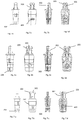
- Figure 1 shows the entirety of a device according to the invention indicated by reference numeral 100 Connecting device.
- Figure 2 is an exploded view of the connecting device 100 in its individual parts.
- the device according to the invention consists of a hollow body 200 which forms the shell of the device in which an activation element 300 is received.
- the hollow body 200 has at least one opening on one side 201.
- These elements 200, 300 and 400 are designed to be die-cast from plastic. This allows economical and series production.
- the individual elements are standard products, they can be easily exchanged. If a single part breaks during use, it can be replaced.
- the connecting device 100 according to the invention is designed in such a way that it can be easily installed manually and / or by machine.
- This activation element 300 is inserted over one of the ends of the hollow body 200.
- the activation element 300 has an opening 301 in its interior, into which the connecting element 400 is introduced and which, in the assembled state, is aligned with the opening of the hollow body 201.
- the connecting element 400 is inserted.
- the connecting element 400 preferably has an elevation 401. This survey is rotatable with coupled to the activation element 300 and, if the connection element 400 is rotated, it is displaced in a longitudinal direction facing away from the end of the hollow body 200, in which the activation element 300 was introduced inside the hollow body 200.
- the lateral opening 201 of the hollow body 200 can advantageously be an elliptical opening in one embodiment. In this way, it is possible to introduce the connecting element 400 with its projection 401 through the lateral opening 201 by connecting the activation element 300 to the hollow body 200.
- a receptacle 501 is made, which has a recess.
- a second receptacle 601 is formed, which advantageously has a cross section in the shape of a double circle.
- a recess is also formed in the first receptacle 501 to receive the annular bead 211, which is formed outside the hollow body 200 and is a stop to the depth of the insertion of the connecting device 100 in the first receptacle 501 and / or in the second Limit inclusion 601.
- the recess in the first receptacle 501 is advantageously designed to be inclined relative to the bottom of the recess 501.
- the second end 208 of the connecting device 100 is inserted into the second receptacle 601. Thanks to the cross-sectional shape with a double circle, the connecting device is automatically centered on the lateral opening 602 of the second receptacle 601.
- the annular bead rests on the second receptacle 601 in such a way that the insertion depth of the second end of the connecting device 100 is limited.
- the first end 206 of the connecting device 100 is introduced into the first receptacle 501.
- the activation element 300 is moved by rotating the connecting element 400. This activation takes place via the lateral bore 602.
- the connecting element 400 By rotating the connecting element 400 and in particular via the projection 401 of the connecting element 400, the activation element 300 is moved within the hollow body 200 in the longitudinal direction. As it moves, the activating element pushes the shoulders 203 outward by moving the head of the end 204. With the advancement of the activation element 300, the second end 208 is also spread apart. This spreading movement is facilitated by the openings 205 provided on the hollow body 200.
- the cross-shaped end structure of the activation element allows the hollow body 200 to be spread open in all directions.
- the wings arranged on the outer surface of the hollow body 200 thus generate greater friction with the surface of the receptacle 601 and prevent the second end 208 of the hollow body 200 from pulling out of the receptacle 601 of the second component 600.
- the feed movement within the hollow body 200 the activation element 300 also spread the wings 202, which they also counteract an extension of the second end from the second receptacle 601. With the advance of the activation element 300, the tip of the activation element 300 also spreads the first end 206.
- the inclined surface 204 of the connecting device 100 according to the invention rests on the, preferably, inclined surface 502 of the receptacle 501.
- the connecting device 100 With the advancement of the activation element 300 and the bearing of the inclined surface of the hollow body 204 against the inclined surface of the receptacle 502, the connecting device 100 shortens the distance between the first component and the second component and in this way provides a connection between the two components with a minimum gap between the parts.
- the outer surface of the hollow body 200 has wings 207. These wings 207 make it more difficult to pull them out of the second receptacle 601 of the second component.
- the first end advantageously has a groove 210 at the base of the shoulders 203, which allows the shoulders 203 to spread more easily.
- the first end 206 also advantageously has two or three shoulders 203.
- the first end can have one or more side guides 213. This or these side guides are used to center the second end within the first receptacle 501.
- the connecting element 400 has an opening 402 with walls that taper from the outside to the inside by reducing the size of the opening in the center of the connecting element 400. This makes it easier to use a tool because it is centered in opening 402.
- the connecting element 400 is snapped into a receptacle at the beginning and at the end of the barrel in order to give the user a wink.
- the device according to the invention can consist entirely of plastic, which allows easy and quick assembly and economical series production.
Landscapes
- Engineering & Computer Science (AREA)
- General Engineering & Computer Science (AREA)
- Mechanical Engineering (AREA)
- Connection Of Plates (AREA)
- Threshing Machine Elements (AREA)
Abstract
Description
- Die vorliegende Erfindung bezieht sich auf eine Verbindungsvorrichtung, insbesondere für Möbel gemäß dem Oberbegriff des Patentanspruchs 1.
- Für die Verbindung von Möbelteilen wird oftmals eine lösbare, wirtschaftliche und möglichst nicht von außen sichtbare Verbindung während der gesamten Lebensdauergefordert.
- Aus
EP 3 302 175 ist eine Verbindungvorrichtung zwischen Möbelbestandteilen bekannt, die ein längs der Längsachse zwischen einem ersten, in einer ersten Aufnahme aufgenommenen und einem zweiten in einer zweiten Aufnahme aufgenommenen Ende gespanntes Gehäuse umfasst. Die Verbindungvorrichtung umfasst einen Zuganker mit veränderlichem Querschnitt. Ein Exzenterteil ist für das Einhaken des Zugankerkopfes zur Verstellung des Zugankers in Klemmrichtungen eingerichtet, sobald dieses Exzenterteil um die eigene Hauptachse X gedreht wird. Durch diese Verstellung spreizt der Zuganker den in der Aufnahme angeordneten Zugankerkopf, die Verbindung zwischen dem Zugankerkopf und der Verbindungsvorrichtung wird jedoch nur durch die Reibung zwischen dem Zugankerkopf und der Möbelaufnahme sichergestellt. - Außerdem erzeugt die so hergestellte Verbindung nur eine Reibungskraft zwischen dem Zugankerkopf und der Möbelaufnahme, jedoch keine Zugkraft zwischen den beiden Möbelteilen.
- Die Patentanmeldung
EP 3 502 491 beschreibt eine Verbindungsvorrichtung zwischen Möbelbestandteilen, umfassend einen länglichen Körper, der sich längs einer eigenen Längsachse zwischen einem in einer ersten im ersten Möbelbestandteil ausgenommenen Aufnahme aufnehmbaren Abschnitt und einem zweiten in einer zweiten im zweiten Möbelteil ausgenommenen Aufnahme aufnehmbaren Abschnitt abwickelt, wobei der längliche Körper einen ersten und einen zweiten spreizbaren Bereich umfasst, die jeweils dem ersten und dem zweiten Abschnitt zugeordnet sind und zwischen einem radial zusammengezogenen Zustand und einem radial gespreizten Zustand verstellbar sind. - Die Verbindungvorrichtung umfasst überdies Stellglieder mit mindestens einem Spreizkörper, der im länglichen Körper aufgenommen und mit mindestens einem ersten und einem zweiten verbreiteten Abschnitt versehen ist, die jeweils dem ersten und dem zweiten Spreizbereich zugeordnet sind. Dieser Spreizkörper ist zwischen einer ersten Stellung, in der er den ersten und den zweiten Spreizbereich in der radial zusammengezogenen Stellung hält und einer zweiten Stellung wahlweise verstellbar, in der der erste und der zweite verbreitete Abschnitt den ersten und den zweiten Spreizbereich in die radial gespreizte Stellung bringen. Das Spreizkörper umfasst eine Vielzahl von zueinander beabstandeten längs der Längsachse radialen Schultern der Art, dass ein Wechsel von Erhöhungen festgelegt wird, mit dem in der radial gespreizten Stellung jede radiale Schulter mit dem ersten Spreizbereich derart unter radialem Druck in Eingriff steht, dass eine verlängerte Spreizung des ersten Spreizbereiches hergestellt wird, der sich mindestens in die radiale Schulter erstreckt.
- Die beschriebene Vorrichtung erfordert, dass der Hohlkörper aus zwei einzelnen Teilen gebildet wird, in denen dann das Aktivierungsteil umschlossen wird, da das Aktivierungsteil Verbreiterungen auf beiden Seiten aufweist, um den Hohlkörper spreizen zu können und auf diese Weise die Verbindungsvorrichtung in den jeweiligen Aufnahmen arretieren zu können. Dies verlangt eine komplexere Stellung und eine Zusatzarbeit während der Montage. Es können überdies Probleme bei der Befestigung der beiden einzelnen Teile entstehen und daher konnte diese Vorrichtung nicht mehr so widerstandsfähig im Gebrauch sein.
- Aus der
SE 1 300 329 - Aus der
DE 10 20043179 ist eine lösbare Verbindungvorrichtung für die Verbindung eines ersten Bauteils mit einem zweiten Bauteil bekannt, die Elemente für die Verankerung des ersten und des zweiten Bauteils umfasst. Insbesondere ist sie der Art ausgebildet, dass sie nicht drehbar symmetrisch mit einer Außenkontur ist, die einen Querschnitt mit zwei Halbkreisen aufweist, die durch zwei Linien verbunden sind. Auf diese Weise wird versucht, die ungewollte Drehung des Gegenstandes zu vermeiden, es wird jedoch noch die Längsbewegung ermöglicht, die Probleme bei der Aktivierung des Verbindungselementes schaffen konnte, da sie mit der Bohrung ausgerichtet werden muss, durch die sie aktiviert wird. - Die Aufgabe der vorliegenden Erfindung ist daher die Ausführung einer Verbindung von zwei Elementen unter lösbarer Arretierung in der Verbindungstellung, wobei eine hohe Standfestigkeit und eine Zugkraft zwischen den beiden Möbelteilen sichergestellt werden soll.
- Diese Aufgabe wird durch eine Verbindungvorrichtung mit den Merkmalen des kennzeichnenden Teils des Patentanspruchs 1 gelöst.
- Es wird eine Verbindungsvorrichtung zwischen zwei Bestandteilen vorgeschlagen, umfassend einen Hohlkörper, der sich längs einer Längsachse zwischen einem ersten, in einer ersten im ersten Bestandteil ausgenommenen Aufnahme auf genommenen und einem zweiten in einer zweiten in einem zweiten Bestandteil ausgenommen Aufnahme aufgenommenen Ende erstreckt, wobei der Hohlkörper bevorzugter Weise mittig einen radial spreizbaren Bereich aufweist, wobei der Hohlkörper an einem seiner Enden eine Öffnung für die Einbringung eines Aktivierungselementes aufweist, wobei das Aktivierungselement innerhalb des Hohlkörpers verschiebbar ist und wobei die Verbindungsvorrichtung dadurch gekennzeichnet ist, dass der Hohlkörper an einem Ende mindestens eine in Richtung des Endes einen Winkel größer als 90° gegenüber der Längsachse des Hohlkörpers aufweist und dass mindestens eine Aufnahme Aussparungen und mindestens eine Öffnung auf ihrer Seitenfläche aufweist, und wobei das Aktivierungselement sich in Richtung eines Endes verjüngt und eine im Wesentlichen mittig angeordnete Öffnung aufweist und das Aktivierungselement und der Hohlkörper bevorzugter Weise über ein Verbindungselement verbunden werden, das den Hohlkörper und das Aktivierungselement verbindet, wobei das Aktivierungselement in der seitlichen Öffnung des Hohlkörpers und in der Öffnung des Aktivierungselementes eingeführt ist, wobei das Verbindungselement auf dieser Weise den Hohlkörper und das Aktivierungselement verbindet, und wobei das Verbindungselement einen Vorsprung aufweist, der drehbar mit dem Aktivierungselement gekoppelt ist und unter Drehung des Verbindungselementes das Aktivierungselement von einer ersten Ruhestellung in eine zweite Arretierstellung bringt, in der das Ende, das eine in Richtung des Endes mit einem Winkel größer als 90° geneigte Fläche aufweist, in der die eine Aussparung aufweisende Aufnahme eingebracht, aufgespreizt wird.
- Die erfindungsgemäße Verbindungvorrichtung weist ein erstes Ende auf, das aus mindestens zwei Klappen besteht, die an ihren freien Enden jeweils eine in Richtung des Endes geneigte Oberfläche aufweisen. Diese geneigte Oberfläche liegt bei Spreizung der Klappen auf der die Aussparung in der Aufnahme bildenden Fläche auf und es wird eine Zugkraft zwischen den beiden zu verbindenden Bestandteilen erzeugt. Vorteilhafter Weise ist das andere Ende der Verbindungvorrichtung vorteilhafter Weise mit einem Querschnitt in der Form eines Doppelkreises ausgebildet, in der sich die beiden Kreise schneiden, jedoch sich überlappen. Die Schnittfläche weist einen Durchmesser kleiner als der Radius eines Kreises auf. Auf diese Art und Weise kann das Ende nur auf zwei vorbestimmten Weisen in der in Bestandteil gebildeten Aufnahme eingeführt werden. Die Aufnahme des Bestandteils, wie auch eine seitliche Öffnung für den Zugang zum Verbindungselement, zentriert den Zugang zum Verbindungselement von außen, da es auf beiden Seiten der Verbindungvorrichtung aktivierbar ist.
- An einem ersten Zeitpunkt wird in einem ersten Bestandteil eine erste Aufnahme für die Befestigung der Verbindungvorrichtung gebildet. Diese erste Aufnahme weist eine Aussparung auf, um eine optimale Befestigung der erfindungsgemäßen Vorrichtung zu erlauben.
- An einem zweiten Zeitpunkt wird in einem zweiten mit dem ersten Bestandteil zu verbindenden Bestandteil eine zweite Aufnahme für die Befestigung der Verbindungvorrichtung hergestellt. Diese zweite Aufnahme ist im Wesentlichen in bevorzugter Weise als ein sich kreuzender Doppelkreis ausgebildet. Diese Aufnahme kann einfach und schnell durch zwei übereinander liegende Bohrungen ausgeführt werden. Auf diese Weise kann auch die Verbindungsvorrichtung zentriert werden. Die zweite Aufnahme weist überdies eine seitliche Öffnung auf, die außerhalb des Bestandteils zugänglich ist. Sobald die Verbindungsvorrichtung in der zweiten Aufnahme bevorzugter Weise eingepresst ist, wird dann das andere Ende der Verbindungsvorrichtung in der ersten Aufnahme mit Aussparung im ersten Bestandteil eingebracht. Nach Einbringung der beiden Enden in den jeweiligen Bestandteilen mittels zum Beispiel eines Werkzeugs wird das Verbindungselement gedreht, das auf diese Weise das Aktivierungselement in Richtung der ersten Aufnahmen schiebt. Mit der Längsbewegung des Aktivierungselementes spreizen sich die am ersten Ende der Verbindungsvorrichtung angeordneten Klappen/Schultern und gleichzeitig wird mit dem Vorschub des Aktivierungselementes auch das zweite Ende gespreizt. Auf diese Weise wird mit der Längsbewegung des Aktivierungselementes eine Befestigung des zweiten Endes der Verbindungvorrichtung hergestellt und es wird auch ein Zug zwischen den beiden Bestandteilen durch das erste Ende der Verbindungsvorrichtung erzeugt, die aufgespreizt werden und die geneigten Oberfläche liegen in der Aussparung der ersten Aufnahme auf und erzeugen eine Anziehungskraft.
- Schon vor der Spreizung, wenn das erste Ende in der ersten Aufnahme eingebracht ist, tritt dieses Ende schnappartig in die Einsparung ein und dies gewährleistet schon vor der Arretierung über das Aktivierungselement die Positionierung der Verbindungsvorrichtung in der ersten Aufnahmen und vermeidet ungewollte Austritte und die Befestigung in einer nicht deckungsgleichen Stellung.
- Bevorzugter Weise weist die Verbindungsvorrichtung zwischen dem ersten in der ersten Aufnahme einfügbaren Bestandteil und dem zweiten in der zweiten Aufnahme einfügbaren Bestandteil einen ringförmige Wulst auf, der als Anschlag dient.
- Der Hohlkörper weist überdies vorteilhafter Weise an seinem zweiten Ende Kerben auf, welche die Spreizung des zweiten Endes durch den Vorschub des Aktivierungselementes erlauben. Das Aktivierungselement ist vorteilhafter Weise durch einen ersten das erste Ende des Hohlkörpers aktivierenden Bereich und einen zweiten die Schultern aktivierenden Bereich mit größerer Breite als der erste Bereich ausgebildet, wobei die Schultern am Hohlkörper anwesend sind und vorteilhafter Weise Flügel aufweisen und in vorgerückter Stellung des Aktivierungselementes werden diese Schultern gespreizt und widersetzen sich dem Auszug aus der Aufnahme, in der die Verbindungsvorrichtung eingebracht wurde.
- Das Aktivierungselement weist nun eine bevorzugter Weise durchgehende Öffnung in seinem Körper auf um das Verbindungselement einbringen zu können. Das Verbindungselement wird der Art eingebracht, dass eine drehbare Kupplung gebildet wird und auf diese Weise, wenn das Verbindungselement zum Beispiel mittels eines Schraubenzieher oder eines anderen Werkzeuges gedreht wird, wird das Aktivierungselement innerhalb des Hohlkörpers verschoben. Das Aktivierungselement weist überdies einen Endteil mit Erhebungen mit Doppelkreuz auf, die in Öffnungen, Spalten an seinem zweiten Ende eingebracht werden können. Diese Erhebungen üben sobald das Aktivierungselement mittels des Verbindungselements verschoben wird, einen Druck auf den Hohlkörper aus und spreizen diesen Letzteren. Durch die Spreizung wird der Hohlkörper besser in der zweiten Aufnahme des Bestandteils eingespannt. Bevorzugter Weise weist auch in diesem Bereich der Hohlkörper Flügel auf seiner Außenfläche auf. Diese Flügel sind der Art angeordnet, dass der Auszug aus der Aufnahme des Bestandteiles schwieriger gestaltet wird.
- Mit der Verschiebung und daher dem Vorschub des Aktivierungselementes des Hohlkörpers schiebt das Ende des Aktivierungselementes das erste Ende des Hohlkörpers und spreizt diesen. Bevorzugter Weise werden die Schultern gespreizt und die geneigten Flächen liegen auf der Oberfläche der ersten Aufnahme des ersten Bestandteils auf. Dank der Neigung der Oberflächen erzeugt die Verbindungsvorrichtung eine Zugkraft zwischen den beiden Bestandteilen.
- Um das Verbindungselement in der zweiten Aufnahme aktivieren zu können, muss eine seitliche Öffnung vorhanden sein, durch die der Benutzer das Verbindungselement dreht und daher das Aktivierungselement verschiebt.
- Das zweite Ende des Hohlkörpers weist vorteilhafter Weise eine Form eines Doppelkreises auf. Auf diese Art ist es möglich, das zweite Ende des Hohlkörpers in die Aufnahme des zweiten Bestandteiles nur in zwei zueinander gespiegelten Stellen einzubringen. Da das Verbindungselement an beiden Seiten aktivierbar ist, kann auf diese Weise der Benutzer auch wenn nur eine Öffnung für den Zugang des Benutzers vorhanden ist, immer das Verbindungselement erreichen. Dies ist besonders vorteilhaft, da, wollte man an einem zweiten Zeitpunkt von neuem die Verbindung lösen, die Verbindungsvorrichtung während ihrer Lebensdauer nicht gedreht werden kann, da die Aufnahme im zweiten Bestandteil keine Drehung der Verbindungsvorrichtung erlaubt.
- Weitere Merkmale und Einzelheiten gehen aus den Patentansprüchen und aus der folgenden Beschreibung von in der beiliegenden Zeichnung dargestellten Ausführungsformen hervor, in der zeigen,
- Figur 1
- eine perspektivische Ansicht der erfindungsgemäßen Vorrichtung,
- Figur 2a,2b und c2
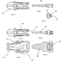
- eine perspektivische Ansicht der einzelnen Teile der erfindungsgemäßen Vorrichtung,
- Figur 3a,3b,3c und 3d
- eine perspektivische Stirnansicht, von oben, von unten und seitlich der erfindungsgemäßen Vorrichtung,
- Figur 4a,4b und 4c
- eine stilisierte Ansicht von oben, von unten und seitlich der erfindungsgemäßen Vorrichtung,
- Figur 5a,5b,5c und 5d
- eine seitliche und stirnseitige Ansicht und einen seitlichen und stirnseitigen Querschnitt der erfindungsgemäßen Vorrichtung während der Schließung,
- Figur 6a,6b,6c und 6d
- eine seitliche und stirnseitige Ansicht und einen seitlichen und stirnseitigen Querschnitt der erfindungsgemäßen Vorrichtung in der geöffneten Stellung,
- Figur 7a,7b,7c und 7d
- eine seitliche und stirnseitige Ansicht und einen seitlichen und stirnseitigen Querschnitt der erfindungsgemäßen Vorrichtung in Arretierstellung,
- Figur 8a und 8b
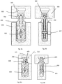
- einen seitlichen und stirnseitigen Querschnitt mit Aufnahmen vor der Einführung,
- Figur 9a und 9b
- einen seitlichen und stirnseitigen Querschnitt mit Aufnahmen während der Einführung,
- Figur 10a und 10b
- einen seitlichen und stirnseitigen Querschnitt mit Aufnahmen in Arretierstellung,
- Figur 11a, 11b, 11c, 12a, 12b, 12c e 12d
- Querschnitte der einzelnen Teile und des Zusammenbaus einer erfindungsgemäßen Vorrichtung in einer weiteren Ausführungsform.
-
Figur 1 zeigt die Gesamtheit einer erfindungsgemäßen mit der Bezugsziffer 100 angegebenen Verbindungsvorrichtung. InFigur 2 ist eine explosionsartig die Verbindungsvorrichtung 100 in ihren Einzelteilen erläutert. Es ist anzumerken, dass die Vorrichtung nur aus drei zueinander leicht montierbaren Elementen besteht. Die erfindungsgemäße Vorrichtung besteht aus einem Hohlkörper 200, der die Schale der Vorrichtung bildet, in der ein Aktivierungselement 300 aufgenommen ist. Der Hohlkörper 200 weist mindestens eine Öffnung auf einer Seite 201 auf. Diese Elemente 200, 300 und 400 sind entworfen um über Druckguss aus Plastik hergestellt zu werden. Dies erlaubt eine wirtschaftliche und serienmäßige Herstellung. Da überdies die einzelnen Elemente serienmäßige Produkte sind, können sie leicht ausgetauscht werden. Sollte während der Verwendung ein einzelnes Teil brechen, so kann es ausgetauscht werden. Die erfindungsgemäße Verbindungsvorrichtung 100 ist derart ausgeführt, dass sie einfach manuell und/oder maschinell montiert werden kann. - Dieses Aktivierungselement 300 wird über eines der Enden des Hohlkörpers 200 eingeführt. Das Aktivierungselement 300 weist in seinem Inneren eine Öffnung 301 auf, in der das Verbindungselement 400 eingebracht und die im montierten Zustand mit der Öffnung des Hohlkörpers 201 ausgerichtet ist. Um das Verbindungselement im Hohlkörper 200 zu befestigen wird das Verbindungselement 400 eingeführt. Das Verbindungselement 400 weist bevorzugter Weise eine Erhebung 401 auf. Diese Erhebung wird drehbar mit dem Aktivierungselement 300 gekoppelt und falls das Verbindungselement 400 gedreht wird dieses in einer dem Ende des Hohlkörpers 200 abgewandten Längsrichtung verschoben, in welcher das Aktivierungselement 300 innerhalb des Hohlkörpers 200 eingeführt wurde.
- In den Figuren von 5a bis 7d sind perspektivische Ansichten und Querschnitte einer erfindungsgemäßen Vorrichtung in den verschiedenen Gebrauchsschritten erläutert. Insbesondere ist zu bemerken, dass vorteilhafter Weise die seitliche Öffnung 201 des Hohlkörpers 200 in einer Ausführungsform eine elliptische Öffnung sein kann. Auf diese Weise ist es möglich, das Verbindungselement 400 mit seinem Vorsprung 401 über die seitliche Öffnung 201 einzuführen, indem das Aktivierungselement 300 mit dem Hohlkörper 200 verbunden wird.
- In den Figuren von 8a bis 10b werden die verschiedenen Schritte während der Montage der Verbindungsvorrichtung in den beiden in den entsprechenden Bestandteilen gebildeten Aufnahmen erläutert. Vorteilhafter Weise sind die Bestandteile Teile von Holzmöbeln oder ähnlichem.
- Im ersten Bestandteil 500 wird eine Aufnahme 501 ausgeführt, die eine Aussparung aufweist. Im zweiten Bestandteil 600 wird eine zweite Aufnahme 601 gebildet, die vorteilhafter Weise einen Querschnitt in der Form eines Doppelkreises aufweist. Überdies wird eine seitliche Öffnung 602 in der zweiten Aufnahme 601 derart ausgeführt, dass außerhalb der in der zweiten Aufnahme 601 eingeführten Verbindungsvorrichtung 100 Zugang gefunden wird.
- Vorteilhafter Weise wird in der ersten Aufnahme 501 überdies eine Aussparung gebildet, um den ringförmigen Wulst 211 aufzunehmen, der außerhalb des Hohlkörpers 200 ausgebildet und ein Anschlag ist, um die Tiefe der Einführung der Verbindungsvorrichtung 100 in der ersten Aufnahme 501 und/oder in der zweiten Aufnahme 601 zu begrenzen.
- Vorteilhafter Weise ist die Aussparung in der ersten Aufnahme 501 gegenüber dem Boden der Aussparung 501 geneigt ausgebildet.
- In einem ersten Schritt der Verbindungsvorrichtung 100 wird in der zweiten Aufnahme 601 das zweite Ende 208 der Verbindungsvorrichtung 100 eingeführt. Dank der Querschnittsform mit Doppelkreis wird die Verbindungvorrichtung selbsttätig auf die seitliche Öffnung 602 der zweiten Aufnahme 601 zentriert. In einem zweiten Schritt, wie in den
Figuren 9a e 9b dargestellt, liegt der ringförmige Wulst auf die zweite Aufnahme 601 derart auf, dass die Einführungstiefe des zweiten Endes der Verbindungsvorrichtung 100 begrenzt wird. Das erste Ende 206 der Verbindungsvorrichtung 100 wird in die erste Aufnahme 501 eingebracht. - Am Ende der Einführung des ersten Endes 206 in der ersten, eine Aussparung bevorzugter Weise mit einer geneigten Fläche 502 aufweisenden Aufnahme 501 wird das Aktivierungselement 300 durch Drehung des Verbindungselementes 400 bewegt. Diese Aktivierung erfolgt über die seitliche Bohrung 602. Durch die Drehung des Verbindungselementes 400 und insbesondere über den Vorsprung 401 des Verbindungselementes 400 wird das Aktivierungselement 300 innerhalb des Hohlkörpers 200 in Längsrichtung bewegt. Durch seine Bewegung schiebt das Aktivierungselement die Schultern 203 nach außen, indem der Kopf des Endes 204 bewegt wird. Mit dem Vorschub des Aktivierungselementes 300 wird auch das zweite Ende 208 gespreizt. Diese Spreizbewegung wird durch die am Hohlkörper 200 vorgesehenen Öffnungen 205 erleichtert. Die kreuzförmige Endstruktur des Aktivierungselementes erlaubt den Hohlkörper 200 in allen Richtungen aufzuspreizen. Die auf der Außenfläche des Hohlkörpers 200 angeordneten Flügel erzeugen so eine größere Reibung mit der Oberfläche der Aufnahme 601 und vermeiden einen Auszug des zweiten Endes 208 des Hohlkörpers 200 aus der Aufnahme 601 des zweiten Bestandteils 600. Vorteilhafter Weise wird mit der Vorschubbewegung innerhalb des Hohlkörpers 200 das Aktivierungselement 300 auch die Flügel 202 spreizen, die auch sie einem Auszug des zweiten Endes aus der zweiten Aufnahme 601 entgegenwirken. Mit dem Vorschub des Aktivierungselementes 300 spreizt überdies die Spitze des Aktivierungselementes 300 das erste Ende 206. Die geneigte Fläche 204 der erfindungsgemäßen Verbindungsvorrichtung 100 liegt auf der, bevorzugter Weise, geneigten Fläche 502 der Aufnahme 501 auf. Mit dem Vorschub des Aktivierungselementes 300 und der Auflage der geneigten Fläche des Hohlkörpers 204 gegen die geneigte Fläche der Aufnahme 502 verkürzt die Verbindungsvorrichtung 100 den Abstand zwischen dem ersten Bestandteil und dem zweiten Bestandteil und stellt auf diese Weise eine Verbindung zwischen den beiden Bestandteilen mit einem Mindestspalt zwischen den Teilen her.
- In einer bevorzugten Ausführungsform weist der Außenfläche des Hohlkörpers 200 Flügel 207 auf. Diese Flügel 207 erschweren einen ungewollten Auszug aus der zweiten Aufnahme 601 des zweiten Bestandteils.
- Vorteilhafter Weise weist das erste Ende an der Basis der Schultern 203 eine Nut 210 auf, die eine leichtere Spreizung der Schultern 203 erlaubt.
- Das erste Ende 206 weist überdies vorteilhafter Weise zwei oder drei Schultern 203 auf. Um die Einführung des ersten Endes 206 in der Aufnahme zu erleichtern, kann das erste Ende eine oder mehrere Seitenführungen 213 aufweisen. Diese oder diese Seitenführungen dienen dazu um das zweite enden innerhalb der ersten Aufnahme 501 zu zentrieren.
- Vorteilhafter Weise weist das Verbindungselement 400 eine Öffnung 402 mit Wänden auf, die von außen nach innen zulaufen, indem die Abmessung der Öffnung in der Mitte des Verbindungselementes 400 reduziert wird. Auf diese Weise kann ein Werkzeug leichter Verwendung finden, da es in der Öffnung 402 zentriert wird.
- Vorteilhafter Weise wird das Verbindungselement 400 in einer Aufnahme am Anfang und am Ende des Laufes schnappartig arretiert um dem Benutzer einen Wink zu geben.
- Die erfindungsgemäße Vorrichtung kann vollständig aufgrund ihrer Ausführung und Geometrie aus Kunststoff bestehen, der eine leichte und schnelle Montage und eine wirtschaftliche serienmäßige Produktion erlaubt.
- Zahlreich sind die Möglichkeiten Varianten und Vorschläge vorzustellen, die am Schutzbereich des erfindungsgemäßen Gegenstandes vorgenommen werden können, der in der folgenden Patentansprüchen festgelegt ist. Die einzelnen Schritte des erfindungsgemäßen Verfahrens können in ihrer Abfolge geändert werden ohne dadurch den Schutzbereich der Erfindung zu verlassen.
- Aufstellung der Bezugsziffern
- 100
- Verbindungsvorrichtung
- 101
- Längsachse der Verbindungsvorrichtung
- 200
- Hohlkörper
- 201
- seitliche Öffnung
- 202
- Flügel
- 203
- Schultern
- 204
- geneigte Fläche
- 205
- Öffnungen
- 206
- erstes Ende
- 207
- Flügel
- 208
- zweites Ende
- 210
- Nut
- 211
- ringförmiger Wulst
- 212
- Projektion der geneigten Fläche
- 213
- Seitenführung
- 300
- Aktivierungselement
- 301
- eine Öffnung
- 302
- die Spitze des Aktivierungselementes
- 400
- Verbindungselement
- 401
- Vorsprung
- 402
- Öffnung
- 500
- erstes Bestandteil
- 501
- erste Aufnahme des ersten Bestandteils
- 600
- zweites Bestandteil
- 601
- zweite Aufnahme des zweiten Bestandteils
- 602
- seitliche Öffnung
- Alpha
- Winkel zwischen der Längsachse der Verbindungsvorrichtung und der Projektion der geneigten Fläche
Claims (8)
- Verbindungsvorrichtung zwischen zwei Bestandteilen (100), umfassend- einen Hohlkörper (200), der sich längs einer Längsachse zwischen einem ersten, in einer ersten im ersten Bestandteil (500) ausgenommenen Aufnahme (501) aufgenommenen und einem zweiten in einer zweiten in einem zweiten Bestandteil (600) ausgenommenen Aufnahme (601) aufgenommenen Ende (206, 208) erstreckt, wobei die Verbindungsvorrichtung ein Aktivierungselement (300) umfasst, wobei der Hohlkörper (300) in einem seiner Enden (206, 208) eine Öffnung (400) für die Einbringung des Aktivierungselementes (300) aufweist, wobei das Aktivierungselement innerhalb des Hohlkörpers (200) verschiebbar ist, und dadurch gekennzeichnet ist, dass der Hohlkörper an einem Ende mindestens eine in Richtung des Endes mit einem Winkel (alpha) größer als 90° gegenüber der Längsachse des Hohlkörpers (100) geneigte Fläche aufweist und wobei das Aktivierungselement (300) eine im Wesentlichen mittig angeordnete Öffnung (301) aufweist, wobei der Hohlkörper mindestens eine Öffnung (201) auf der seitlichen Fläche aufweist und die Öffnung des Aktivierungselementes (301) und die Öffnung des Hohlkörpers (201) in montierter Stellung miteinander ausgerichtet sind und die Verbindungsvorrichtung (100) ein Verbindungselement (400) umfasst und dass die Öffnung des Aktivierungselementes (301) das Verbindungselement (400) aufnimmt und das Verbindungselement (400) einen Vorsprung (401) aufweist, der drehbar mit dem Aktivierungselement (300) gekoppelt ist und unter Drehung des Verbindungselementes (400) das Aktivierungselement (300) von einer ersten Ruhestellung in eine zweite Arretierstellung bringt, in der das Ende, das eine in Richtung dieses Endes des Hohlkörpers mit einem Winkel größer als 90° geneigte Öffnung aufweist, in der die eine Aussparung aufweisende Aufnahme (501) eingebracht, aufgespreizt wird.
- Verbindungsvorrichtung zwischen zwei Bestandteilen (100) nach Anspruch 1, dadurch gekennzeichnet, dass das zweite Ende (208) einen Quer schnitt mit sich kreuzendem Doppel kreis auf weist, i n dem die Schnittfläche eine Breite kleiner als der Radius eines der bei den Kreise auf weist.
- Verbindungsvorrichtung zwischen zwei Bestandteilen (100) nach Anspruch 1 oder 2, dadurch gekennzeichnet, dass auf der Außenfläche des Hohlkörpers (200) einringförmi - ger Wulst (211) vorhanden ist, der als Anschlagwirkt.
- Verbindungsvorrichtung zwischen zwei Bestandteilen (100) nach einem der vorstehenden Ansprüche, dadurch gekennzeichnet, dass das erste Ende (206) an der Basis der Schultern (203) Nuten (210) auf weist.
- Verbindungsvorrichtung zwischen zwei Bestandteilen (100) nach einem der vorst ehenden Ansprüche, dadurch gekennzeichnet, dass das erste Ende zwei oder drei Schultern (203) aufweist.
- Verbindungsvorrichtung zwischen zwei Bestandteilen (100) nach einem der vorstehenden Ansprüche, dadurch gekennzeichnet, dass das erste Ende äußere Führungen (213) auf - weist.
- Verbindungsvorrichtung zwischen zwei Bestandteilen (100) nach einem der vorstehenden Ansprüche, dadurch gekennzeichnet, dass das Aktivier ungsel ement (300) an einem Ende einen Querschnitt mit Doppelkreuzform auf - weist.
- Verbindungsvorrichtung zwischen zwei Bestandteilen (100) nach einem der vorstehenden Ansprüche, dadurch gekennzeichnet, dass eine Öffnung (402) des Verbindungselement es (400) Wände auf weist, die in Richtung der Mitte des Verbindungselement es (400) zusammenlaufen.
Applications Claiming Priority (1)
| Application Number | Priority Date | Filing Date | Title |
|---|---|---|---|
| IT102019000012105A IT201900012105A1 (it) | 2019-07-17 | 2019-07-17 | Dispositivo di giunzione in particolare per mobili |
Publications (2)
| Publication Number | Publication Date |
|---|---|
| EP3766384A1 true EP3766384A1 (de) | 2021-01-20 |
| EP3766384B1 EP3766384B1 (de) | 2022-03-09 |
Family
ID=68582194
Family Applications (1)
| Application Number | Title | Priority Date | Filing Date |
|---|---|---|---|
| EP20186144.0A Active EP3766384B1 (de) | 2019-07-17 | 2020-07-16 | Verbindungsvorrichtung insbesondere für möbel |
Country Status (2)
| Country | Link |
|---|---|
| EP (1) | EP3766384B1 (de) |
| IT (1) | IT201900012105A1 (de) |
Cited By (2)
| Publication number | Priority date | Publication date | Assignee | Title |
|---|---|---|---|---|
| EP4118346A1 (de) * | 2020-03-10 | 2023-01-18 | Effegi Brevetti S.r.l. | Verbesserte verbindungsvorrichtung für möbelteile und möbelzubehör |
| EP4650609A1 (de) * | 2024-05-15 | 2025-11-19 | Festool GmbH | Verbinder zum mechanischen verbinden eines ersten werkstücks mit einem zweiten werkstück, anordnung und verfahren zum betreiben eines verbinders |
Citations (4)
| Publication number | Priority date | Publication date | Assignee | Title |
|---|---|---|---|---|
| EP0930436A1 (de) * | 1998-01-19 | 1999-07-21 | Fiorello Giovannetti | Befestigungsmittel für lösbare Verbindungen von Platten |
| SE1300329A1 (sv) | 2013-05-10 | 2014-11-11 | Furnparts Ab | Anordning för lösbart sammanfästande av möbeldelar såsom skivor |
| EP3302175A1 (de) | 2015-06-08 | 2018-04-11 | CAR S.r.l. | Verbindungsvorrichtung zwischen bauteilen eines möbels |
| EP3502491A1 (de) | 2017-12-21 | 2019-06-26 | CAR S.r.l. | Verbindungseinrichtung |
-
2019
- 2019-07-17 IT IT102019000012105A patent/IT201900012105A1/it unknown
-
2020
- 2020-07-16 EP EP20186144.0A patent/EP3766384B1/de active Active
Patent Citations (4)
| Publication number | Priority date | Publication date | Assignee | Title |
|---|---|---|---|---|
| EP0930436A1 (de) * | 1998-01-19 | 1999-07-21 | Fiorello Giovannetti | Befestigungsmittel für lösbare Verbindungen von Platten |
| SE1300329A1 (sv) | 2013-05-10 | 2014-11-11 | Furnparts Ab | Anordning för lösbart sammanfästande av möbeldelar såsom skivor |
| EP3302175A1 (de) | 2015-06-08 | 2018-04-11 | CAR S.r.l. | Verbindungsvorrichtung zwischen bauteilen eines möbels |
| EP3502491A1 (de) | 2017-12-21 | 2019-06-26 | CAR S.r.l. | Verbindungseinrichtung |
Cited By (3)
| Publication number | Priority date | Publication date | Assignee | Title |
|---|---|---|---|---|
| EP4118346A1 (de) * | 2020-03-10 | 2023-01-18 | Effegi Brevetti S.r.l. | Verbesserte verbindungsvorrichtung für möbelteile und möbelzubehör |
| EP4118346B1 (de) * | 2020-03-10 | 2025-05-21 | Effegi Brevetti S.r.l. | Verbesserte verbindungsvorrichtung für möbelteile und möbelzubehör |
| EP4650609A1 (de) * | 2024-05-15 | 2025-11-19 | Festool GmbH | Verbinder zum mechanischen verbinden eines ersten werkstücks mit einem zweiten werkstück, anordnung und verfahren zum betreiben eines verbinders |
Also Published As
| Publication number | Publication date |
|---|---|
| EP3766384B1 (de) | 2022-03-09 |
| IT201900012105A1 (it) | 2021-01-17 |
Similar Documents
| Publication | Publication Date | Title |
|---|---|---|
| DE60208218T2 (de) | Vorrichtung und verfahren zur lösbaren verbindung aneinanderstossender lasttragender teile und zugglied zur verwendung zur herstellung der vorrichtung | |
| DE19881663C2 (de) | Vorrichtung zur Herstellung einer Verbindung | |
| EP2786026A1 (de) | Profilstab, profilverbund sowie verfahren zum herstellen eines profilverbundes | |
| DE202016008130U1 (de) | Verbindungsvorrichtung zwischen den Komponenten eines Möbels | |
| EP0370172B1 (de) | Vorrichtung zur stufenweisen Höhenverstellung eines Befestigungs- oder Umlenkpunktes für einen Sicherheitsgurt o. dgl. | |
| EP3060823B2 (de) | Verfahren zur herstellung eines trägerkörpers mit tilgermasse zur veränderung der schwingung für einen bremsbelag einer scheibenbremse | |
| DE112017006304T5 (de) | Seitlich aktivierter modularer bohrer | |
| EP2450492A1 (de) | System zum Befestigen eines Sanitärartikels | |
| DE102019116160A1 (de) | Seitlich geschlossener modularer Bohrer mit federunterstütztem Auswurf | |
| DE2917611A1 (de) | Duebel, werkzeug und verfahren zum herstellen einer bohrung fuer den duebel und werkzeug zum einsetzen des duebels | |
| EP3766384B1 (de) | Verbindungsvorrichtung insbesondere für möbel | |
| DE3329047C2 (de) | Verfahren zum Herstellen eines Spreizdübels | |
| DE2646007A1 (de) | Verankerungsduebel | |
| DE2361846A1 (de) | Vorrichtung zur verriegelung eines elements in einer erforderlichen gebrauchsstellung | |
| DE102017121382A1 (de) | Blendenträger und Schubkasten | |
| AT524730B1 (de) | Wandbauteil für eine Schublade, Schublade und Möbel | |
| EP1455096A2 (de) | Mit Spiralwirkung arbeitende Befestigung zwischen Wänden und/oder Regalbrettern von Möbelstücken | |
| DE102008018692B3 (de) | Eckverbindung für Bettgestelle, die insbesondere metallfrei sind | |
| DE2627650A1 (de) | Befestigungssatz mit spreizduebel und befestigungsschraube | |
| EP2740947B1 (de) | Befestigungssystem mit entkoppelbarem Halteteller | |
| DE2731761B2 (de) | Hohlraumbefestigung | |
| DE202012104972U1 (de) | Ankerverbinder | |
| EP2802432B1 (de) | Werkzeug zum erzeugen eines ringförmigen hinterschnittes in einem körper, verfahren zum festlegen eines dübels in einem körper, dübel zum einsetzen in eine bohrung und verwendung eines dübels | |
| DE3328232C2 (de) | Raumfachwerk | |
| DE2650713A1 (de) | Spreizbolzen |
Legal Events
| Date | Code | Title | Description |
|---|---|---|---|
| PUAI | Public reference made under article 153(3) epc to a published international application that has entered the european phase |
Free format text: ORIGINAL CODE: 0009012 |
|
| STAA | Information on the status of an ep patent application or granted ep patent |
Free format text: STATUS: THE APPLICATION HAS BEEN PUBLISHED |
|
| AK | Designated contracting states |
Kind code of ref document: A1 Designated state(s): AL AT BE BG CH CY CZ DE DK EE ES FI FR GB GR HR HU IE IS IT LI LT LU LV MC MK MT NL NO PL PT RO RS SE SI SK SM TR |
|
| AX | Request for extension of the european patent |
Extension state: BA ME |
|
| STAA | Information on the status of an ep patent application or granted ep patent |
Free format text: STATUS: REQUEST FOR EXAMINATION WAS MADE |
|
| 17P | Request for examination filed |
Effective date: 20210416 |
|
| RBV | Designated contracting states (corrected) |
Designated state(s): AL AT BE BG CH CY CZ DE DK EE ES FI FR GB GR HR HU IE IS IT LI LT LU LV MC MK MT NL NO PL PT RO RS SE SI SK SM TR |
|
| GRAP | Despatch of communication of intention to grant a patent |
Free format text: ORIGINAL CODE: EPIDOSNIGR1 |
|
| STAA | Information on the status of an ep patent application or granted ep patent |
Free format text: STATUS: GRANT OF PATENT IS INTENDED |
|
| INTG | Intention to grant announced |
Effective date: 20211022 |
|
| GRAS | Grant fee paid |
Free format text: ORIGINAL CODE: EPIDOSNIGR3 |
|
| GRAA | (expected) grant |
Free format text: ORIGINAL CODE: 0009210 |
|
| STAA | Information on the status of an ep patent application or granted ep patent |
Free format text: STATUS: THE PATENT HAS BEEN GRANTED |
|
| AK | Designated contracting states |
Kind code of ref document: B1 Designated state(s): AL AT BE BG CH CY CZ DE DK EE ES FI FR GB GR HR HU IE IS IT LI LT LU LV MC MK MT NL NO PL PT RO RS SE SI SK SM TR |
|
| REG | Reference to a national code |
Ref country code: CH Ref legal event code: EP Ref country code: AT Ref legal event code: REF Ref document number: 1473439 Country of ref document: AT Kind code of ref document: T Effective date: 20220315 |
|
| REG | Reference to a national code |
Ref country code: DE Ref legal event code: R096 Ref document number: 502020000775 Country of ref document: DE |
|
| REG | Reference to a national code |
Ref country code: IE Ref legal event code: FG4D Free format text: LANGUAGE OF EP DOCUMENT: GERMAN |
|
| REG | Reference to a national code |
Ref country code: LT Ref legal event code: MG9D |
|
| REG | Reference to a national code |
Ref country code: NL Ref legal event code: MP Effective date: 20220309 |
|
| PG25 | Lapsed in a contracting state [announced via postgrant information from national office to epo] |
Ref country code: SE Free format text: LAPSE BECAUSE OF FAILURE TO SUBMIT A TRANSLATION OF THE DESCRIPTION OR TO PAY THE FEE WITHIN THE PRESCRIBED TIME-LIMIT Effective date: 20220309 Ref country code: RS Free format text: LAPSE BECAUSE OF FAILURE TO SUBMIT A TRANSLATION OF THE DESCRIPTION OR TO PAY THE FEE WITHIN THE PRESCRIBED TIME-LIMIT Effective date: 20220309 Ref country code: NO Free format text: LAPSE BECAUSE OF FAILURE TO SUBMIT A TRANSLATION OF THE DESCRIPTION OR TO PAY THE FEE WITHIN THE PRESCRIBED TIME-LIMIT Effective date: 20220609 Ref country code: LT Free format text: LAPSE BECAUSE OF FAILURE TO SUBMIT A TRANSLATION OF THE DESCRIPTION OR TO PAY THE FEE WITHIN THE PRESCRIBED TIME-LIMIT Effective date: 20220309 Ref country code: HR Free format text: LAPSE BECAUSE OF FAILURE TO SUBMIT A TRANSLATION OF THE DESCRIPTION OR TO PAY THE FEE WITHIN THE PRESCRIBED TIME-LIMIT Effective date: 20220309 Ref country code: BG Free format text: LAPSE BECAUSE OF FAILURE TO SUBMIT A TRANSLATION OF THE DESCRIPTION OR TO PAY THE FEE WITHIN THE PRESCRIBED TIME-LIMIT Effective date: 20220609 |
|
| PG25 | Lapsed in a contracting state [announced via postgrant information from national office to epo] |
Ref country code: LV Free format text: LAPSE BECAUSE OF FAILURE TO SUBMIT A TRANSLATION OF THE DESCRIPTION OR TO PAY THE FEE WITHIN THE PRESCRIBED TIME-LIMIT Effective date: 20220309 Ref country code: GR Free format text: LAPSE BECAUSE OF FAILURE TO SUBMIT A TRANSLATION OF THE DESCRIPTION OR TO PAY THE FEE WITHIN THE PRESCRIBED TIME-LIMIT Effective date: 20220610 Ref country code: FI Free format text: LAPSE BECAUSE OF FAILURE TO SUBMIT A TRANSLATION OF THE DESCRIPTION OR TO PAY THE FEE WITHIN THE PRESCRIBED TIME-LIMIT Effective date: 20220309 |
|
| PG25 | Lapsed in a contracting state [announced via postgrant information from national office to epo] |
Ref country code: NL Free format text: LAPSE BECAUSE OF FAILURE TO SUBMIT A TRANSLATION OF THE DESCRIPTION OR TO PAY THE FEE WITHIN THE PRESCRIBED TIME-LIMIT Effective date: 20220309 |
|
| PG25 | Lapsed in a contracting state [announced via postgrant information from national office to epo] |
Ref country code: SM Free format text: LAPSE BECAUSE OF FAILURE TO SUBMIT A TRANSLATION OF THE DESCRIPTION OR TO PAY THE FEE WITHIN THE PRESCRIBED TIME-LIMIT Effective date: 20220309 Ref country code: SK Free format text: LAPSE BECAUSE OF FAILURE TO SUBMIT A TRANSLATION OF THE DESCRIPTION OR TO PAY THE FEE WITHIN THE PRESCRIBED TIME-LIMIT Effective date: 20220309 Ref country code: RO Free format text: LAPSE BECAUSE OF FAILURE TO SUBMIT A TRANSLATION OF THE DESCRIPTION OR TO PAY THE FEE WITHIN THE PRESCRIBED TIME-LIMIT Effective date: 20220309 Ref country code: PT Free format text: LAPSE BECAUSE OF FAILURE TO SUBMIT A TRANSLATION OF THE DESCRIPTION OR TO PAY THE FEE WITHIN THE PRESCRIBED TIME-LIMIT Effective date: 20220711 Ref country code: ES Free format text: LAPSE BECAUSE OF FAILURE TO SUBMIT A TRANSLATION OF THE DESCRIPTION OR TO PAY THE FEE WITHIN THE PRESCRIBED TIME-LIMIT Effective date: 20220309 Ref country code: EE Free format text: LAPSE BECAUSE OF FAILURE TO SUBMIT A TRANSLATION OF THE DESCRIPTION OR TO PAY THE FEE WITHIN THE PRESCRIBED TIME-LIMIT Effective date: 20220309 Ref country code: CZ Free format text: LAPSE BECAUSE OF FAILURE TO SUBMIT A TRANSLATION OF THE DESCRIPTION OR TO PAY THE FEE WITHIN THE PRESCRIBED TIME-LIMIT Effective date: 20220309 |
|
| PG25 | Lapsed in a contracting state [announced via postgrant information from national office to epo] |
Ref country code: PL Free format text: LAPSE BECAUSE OF FAILURE TO SUBMIT A TRANSLATION OF THE DESCRIPTION OR TO PAY THE FEE WITHIN THE PRESCRIBED TIME-LIMIT Effective date: 20220309 Ref country code: IS Free format text: LAPSE BECAUSE OF FAILURE TO SUBMIT A TRANSLATION OF THE DESCRIPTION OR TO PAY THE FEE WITHIN THE PRESCRIBED TIME-LIMIT Effective date: 20220709 Ref country code: AL Free format text: LAPSE BECAUSE OF FAILURE TO SUBMIT A TRANSLATION OF THE DESCRIPTION OR TO PAY THE FEE WITHIN THE PRESCRIBED TIME-LIMIT Effective date: 20220309 |
|
| REG | Reference to a national code |
Ref country code: DE Ref legal event code: R097 Ref document number: 502020000775 Country of ref document: DE |
|
| PLBE | No opposition filed within time limit |
Free format text: ORIGINAL CODE: 0009261 |
|
| STAA | Information on the status of an ep patent application or granted ep patent |
Free format text: STATUS: NO OPPOSITION FILED WITHIN TIME LIMIT |
|
| PG25 | Lapsed in a contracting state [announced via postgrant information from national office to epo] |
Ref country code: DK Free format text: LAPSE BECAUSE OF FAILURE TO SUBMIT A TRANSLATION OF THE DESCRIPTION OR TO PAY THE FEE WITHIN THE PRESCRIBED TIME-LIMIT Effective date: 20220309 |
|
| 26N | No opposition filed |
Effective date: 20221212 |
|
| PG25 | Lapsed in a contracting state [announced via postgrant information from national office to epo] |
Ref country code: SI Free format text: LAPSE BECAUSE OF FAILURE TO SUBMIT A TRANSLATION OF THE DESCRIPTION OR TO PAY THE FEE WITHIN THE PRESCRIBED TIME-LIMIT Effective date: 20220309 Ref country code: MC Free format text: LAPSE BECAUSE OF FAILURE TO SUBMIT A TRANSLATION OF THE DESCRIPTION OR TO PAY THE FEE WITHIN THE PRESCRIBED TIME-LIMIT Effective date: 20220309 |
|
| REG | Reference to a national code |
Ref country code: BE Ref legal event code: MM Effective date: 20220731 |
|
| PG25 | Lapsed in a contracting state [announced via postgrant information from national office to epo] |
Ref country code: LU Free format text: LAPSE BECAUSE OF NON-PAYMENT OF DUE FEES Effective date: 20220716 Ref country code: FR Free format text: LAPSE BECAUSE OF NON-PAYMENT OF DUE FEES Effective date: 20220731 |
|
| PG25 | Lapsed in a contracting state [announced via postgrant information from national office to epo] |
Ref country code: BE Free format text: LAPSE BECAUSE OF NON-PAYMENT OF DUE FEES Effective date: 20220731 |
|
| PG25 | Lapsed in a contracting state [announced via postgrant information from national office to epo] |
Ref country code: IE Free format text: LAPSE BECAUSE OF NON-PAYMENT OF DUE FEES Effective date: 20220716 |
|
| PG25 | Lapsed in a contracting state [announced via postgrant information from national office to epo] |
Ref country code: MK Free format text: LAPSE BECAUSE OF FAILURE TO SUBMIT A TRANSLATION OF THE DESCRIPTION OR TO PAY THE FEE WITHIN THE PRESCRIBED TIME-LIMIT Effective date: 20220309 Ref country code: CY Free format text: LAPSE BECAUSE OF FAILURE TO SUBMIT A TRANSLATION OF THE DESCRIPTION OR TO PAY THE FEE WITHIN THE PRESCRIBED TIME-LIMIT Effective date: 20220309 |
|
| PG25 | Lapsed in a contracting state [announced via postgrant information from national office to epo] |
Ref country code: HU Free format text: LAPSE BECAUSE OF FAILURE TO SUBMIT A TRANSLATION OF THE DESCRIPTION OR TO PAY THE FEE WITHIN THE PRESCRIBED TIME-LIMIT; INVALID AB INITIO Effective date: 20200716 |
|
| PG25 | Lapsed in a contracting state [announced via postgrant information from national office to epo] |
Ref country code: MT Free format text: LAPSE BECAUSE OF FAILURE TO SUBMIT A TRANSLATION OF THE DESCRIPTION OR TO PAY THE FEE WITHIN THE PRESCRIBED TIME-LIMIT Effective date: 20220309 |
|
| GBPC | Gb: european patent ceased through non-payment of renewal fee |
Effective date: 20240716 |
|
| PG25 | Lapsed in a contracting state [announced via postgrant information from national office to epo] |
Ref country code: GB Free format text: LAPSE BECAUSE OF NON-PAYMENT OF DUE FEES Effective date: 20240716 |
|
| PGFP | Annual fee paid to national office [announced via postgrant information from national office to epo] |
Ref country code: DE Payment date: 20250729 Year of fee payment: 6 |
|
| PGFP | Annual fee paid to national office [announced via postgrant information from national office to epo] |
Ref country code: IT Payment date: 20250722 Year of fee payment: 6 |
|
| PGFP | Annual fee paid to national office [announced via postgrant information from national office to epo] |
Ref country code: AT Payment date: 20250702 Year of fee payment: 6 |
|
| PGFP | Annual fee paid to national office [announced via postgrant information from national office to epo] |
Ref country code: CH Payment date: 20250801 Year of fee payment: 6 |
|
| PG25 | Lapsed in a contracting state [announced via postgrant information from national office to epo] |
Ref country code: TR Free format text: LAPSE BECAUSE OF FAILURE TO SUBMIT A TRANSLATION OF THE DESCRIPTION OR TO PAY THE FEE WITHIN THE PRESCRIBED TIME-LIMIT Effective date: 20220309 |