EP3766384A1 - Dispositif de connexion, notamment pour les meubles - Google Patents
Dispositif de connexion, notamment pour les meubles Download PDFInfo
- Publication number
- EP3766384A1 EP3766384A1 EP20186144.0A EP20186144A EP3766384A1 EP 3766384 A1 EP3766384 A1 EP 3766384A1 EP 20186144 A EP20186144 A EP 20186144A EP 3766384 A1 EP3766384 A1 EP 3766384A1
- Authority
- EP
- European Patent Office
- Prior art keywords
- hollow body
- connecting device
- opening
- activation element
- receptacle
- Prior art date
- Legal status (The legal status is an assumption and is not a legal conclusion. Google has not performed a legal analysis and makes no representation as to the accuracy of the status listed.)
- Granted
Links
Images


Classifications
-
- A—HUMAN NECESSITIES
- A47—FURNITURE; DOMESTIC ARTICLES OR APPLIANCES; COFFEE MILLS; SPICE MILLS; SUCTION CLEANERS IN GENERAL
- A47B—TABLES; DESKS; OFFICE FURNITURE; CABINETS; DRAWERS; GENERAL DETAILS OF FURNITURE
- A47B96/00—Details of cabinets, racks or shelf units not covered by a single one of groups A47B43/00 - A47B95/00; General details of furniture
- A47B96/06—Brackets or similar supporting means for cabinets, racks or shelves
- A47B96/066—Supporting means received within an edge of the shelf
-
- F—MECHANICAL ENGINEERING; LIGHTING; HEATING; WEAPONS; BLASTING
- F16—ENGINEERING ELEMENTS AND UNITS; GENERAL MEASURES FOR PRODUCING AND MAINTAINING EFFECTIVE FUNCTIONING OF MACHINES OR INSTALLATIONS; THERMAL INSULATION IN GENERAL
- F16B—DEVICES FOR FASTENING OR SECURING CONSTRUCTIONAL ELEMENTS OR MACHINE PARTS TOGETHER, e.g. NAILS, BOLTS, CIRCLIPS, CLAMPS, CLIPS OR WEDGES; JOINTS OR JOINTING
- F16B12/00—Jointing of furniture or the like, e.g. hidden from exterior
- F16B12/10—Jointing of furniture or the like, e.g. hidden from exterior using pegs, bolts, tenons, clamps, clips, or the like
- F16B12/12—Jointing of furniture or the like, e.g. hidden from exterior using pegs, bolts, tenons, clamps, clips, or the like for non-metal furniture parts, e.g. made of wood, of plastics
- F16B12/20—Jointing of furniture or the like, e.g. hidden from exterior using pegs, bolts, tenons, clamps, clips, or the like for non-metal furniture parts, e.g. made of wood, of plastics using clamps, clips, wedges, sliding bolts, or the like
- F16B12/2009—Jointing of furniture or the like, e.g. hidden from exterior using pegs, bolts, tenons, clamps, clips, or the like for non-metal furniture parts, e.g. made of wood, of plastics using clamps, clips, wedges, sliding bolts, or the like actuated by rotary motion
- F16B12/2027—Jointing of furniture or the like, e.g. hidden from exterior using pegs, bolts, tenons, clamps, clips, or the like for non-metal furniture parts, e.g. made of wood, of plastics using clamps, clips, wedges, sliding bolts, or the like actuated by rotary motion with rotating excenters or wedges
-
- F—MECHANICAL ENGINEERING; LIGHTING; HEATING; WEAPONS; BLASTING
- F16—ENGINEERING ELEMENTS AND UNITS; GENERAL MEASURES FOR PRODUCING AND MAINTAINING EFFECTIVE FUNCTIONING OF MACHINES OR INSTALLATIONS; THERMAL INSULATION IN GENERAL
- F16B—DEVICES FOR FASTENING OR SECURING CONSTRUCTIONAL ELEMENTS OR MACHINE PARTS TOGETHER, e.g. NAILS, BOLTS, CIRCLIPS, CLAMPS, CLIPS OR WEDGES; JOINTS OR JOINTING
- F16B12/00—Jointing of furniture or the like, e.g. hidden from exterior
- F16B12/10—Jointing of furniture or the like, e.g. hidden from exterior using pegs, bolts, tenons, clamps, clips, or the like
- F16B12/12—Jointing of furniture or the like, e.g. hidden from exterior using pegs, bolts, tenons, clamps, clips, or the like for non-metal furniture parts, e.g. made of wood, of plastics
- F16B12/20—Jointing of furniture or the like, e.g. hidden from exterior using pegs, bolts, tenons, clamps, clips, or the like for non-metal furniture parts, e.g. made of wood, of plastics using clamps, clips, wedges, sliding bolts, or the like
- F16B12/2009—Jointing of furniture or the like, e.g. hidden from exterior using pegs, bolts, tenons, clamps, clips, or the like for non-metal furniture parts, e.g. made of wood, of plastics using clamps, clips, wedges, sliding bolts, or the like actuated by rotary motion
- F16B12/2054—Jointing of furniture or the like, e.g. hidden from exterior using pegs, bolts, tenons, clamps, clips, or the like for non-metal furniture parts, e.g. made of wood, of plastics using clamps, clips, wedges, sliding bolts, or the like actuated by rotary motion with engaging screw threads as securing means for limiting movement
- F16B12/2063—Jointing of furniture or the like, e.g. hidden from exterior using pegs, bolts, tenons, clamps, clips, or the like for non-metal furniture parts, e.g. made of wood, of plastics using clamps, clips, wedges, sliding bolts, or the like actuated by rotary motion with engaging screw threads as securing means for limiting movement with engaging screw threads as tightening means
Definitions
- the present invention relates to a connecting device, in particular for furniture according to the preamble of patent claim 1.
- connection device between furniture components which comprises a housing stretched along the longitudinal axis between a first end received in a first receptacle and a second end received in a second receptacle.
- the connecting device comprises a tie rod with a variable cross section.
- An eccentric part is set up for hooking the tie rod head in order to adjust the tie rod in the clamping directions as soon as this eccentric part is rotated about its own main axis X.
- the tie rod spreads the tie rod head arranged in the receptacle, but the connection between the tie rod head and the connecting device is only ensured by the friction between the tie rod head and the furniture receptacle.
- connection produced in this way only generates a frictional force between the tie rod head and the furniture receptacle, but no tensile force between the two furniture parts.
- the patent application EP 3,502,491 describes a connecting device between furniture components, comprising an elongated body which unwinds along its own longitudinal axis between a portion receivable in a first recess recessed in the first furniture component and a second portion receivable in a second recess recessed in the second furniture part, the elongated body having a first and a second expandable region, which are each associated with the first and the second section and are adjustable between a radially contracted state and a radially expanded state.
- the connecting device also comprises actuators with at least one expansion body, which is received in the elongate body and provided with at least a first and a second widened section, which are each assigned to the first and the second expansion area.
- This expansion body is selectively adjustable between a first position in which it holds the first and the second expansion area in the radially contracted position and a second position in which the first and the second widened section Bring the first and the second expansion area into the radially expanded position.
- the expansion body comprises a plurality of spaced apart along the longitudinal axis radial shoulders such that an alternation of elevations is determined, with which in the radially expanded position each radial shoulder with the first expansion area engages under radial pressure such that an extended expansion of the first expansion region is produced, which extends at least into the radial shoulder.
- the device described requires that the hollow body is formed from two individual parts in which the activation part is then enclosed, since the activation part has widenings on both sides in order to be able to spread the hollow body and in this way to lock the connecting device in the respective receptacles can.
- This requires a more complex position and additional work during assembly.
- problems can arise with the attachment of the two individual parts and therefore this device could no longer be as robust in use.
- a releasable connecting device for connecting a first Component with a second component known which comprises elements for anchoring the first and the second component.
- it is designed such that it is non-rotatably symmetrical with an outer contour which has a cross section with two semicircles, which are connected by two lines. In this way an attempt is made to avoid the unwanted rotation of the object, but it is still possible the longitudinal movement which could create problems with the activation of the connecting element, since it has to be aligned with the bore through which it is activated.
- the object of the present invention is therefore to implement a connection of two elements with releasable locking in the connection position, with a high level of stability and a tensile force between the two furniture parts to be ensured.
- a connecting device between two components comprising a hollow body which extends along a longitudinal axis between a first end received in a first recess recessed in the first component and a second end received in a second recess recessed in a second component, the Hollow body preferably has a radially expandable area in the center, the hollow body having an opening at one of its ends for the introduction of an activation element, the activation element being displaceable within the hollow body and the connecting device being characterized in that the hollow body has at least one at one end in the direction of the end has an angle greater than 90 ° with respect to the longitudinal axis of the hollow body and that at least one receptacle has recesses and at least one opening on its side surface, and wherein the activation element tapers in the direction of one end and has a substantially centrally arranged opening and the activation element and the hollow body are preferably connected via a connecting element which connects the hollow body and the activation element, the activation element in the lateral opening of the hollow body and in the
- the connecting device has a first end which consists of at least two flaps which each have a surface inclined in the direction of the end at their free ends. When the flaps are spread, this inclined surface rests on the surface forming the recess in the receptacle and a tensile force is generated between the two components to be connected.
- the other end of the connecting device is advantageously designed with a cross section in the shape of a double circle, in which the two circles intersect but overlap.
- the cut surface has a diameter smaller than the radius of a circle. In this way the end can only be inserted into the constituent receptacle in two predetermined ways.
- the inclusion of the component, as well as a side opening for access to the connecting element centers the access to the connecting element from the outside, since it can be activated on both sides of the connecting device.
- a first receptacle for fastening the connecting device is formed in a first component.
- This first receptacle has a recess to to allow an optimal attachment of the device according to the invention.
- a second receptacle for fastening the connecting device is produced.
- This second receptacle is essentially designed in a preferred manner as a crossing double circle. This recording can be carried out quickly and easily using two boreholes lying one above the other. In this way, the connecting device can also be centered.
- the second receptacle also has a side opening that is accessible outside of the component. As soon as the connecting device is preferably pressed into the second receptacle, the other end of the connecting device is then introduced into the first receptacle with a recess in the first component.
- the connecting element is rotated, which in this way pushes the activation element in the direction of the first receptacles.
- the flaps / shoulders arranged at the first end of the connecting device spread apart and, at the same time, as the activation element is advanced, the second end is also spread apart.
- the second end of the connecting device is fastened and a tension is also created between the two components through the first end of the connecting device, which are spread apart and the inclined surfaces rest in the recess of the first receptacle and generate an attractive force.
- the connecting device preferably has an annular bead, which serves as a stop, between the first component that can be inserted into the first receptacle and the second component that can be inserted into the second receptacle.
- the hollow body also advantageously has notches at its second end, which allow the second end to be spread by the advancement of the activation element.
- the activation element is advantageously formed by a first area that activates the first end of the hollow body and a second area that activates the shoulders and is wider than the first area, wherein the shoulders are present on the hollow body and advantageously have wings and in the advanced position of the activation element, these shoulders are spread and oppose the extraction from the receptacle in which the connecting device was introduced.
- the activation element now preferably has a continuous opening in its body in order to be able to introduce the connecting element.
- the connecting element is introduced in such a way that a rotatable coupling is formed and in this way, when the connecting element is rotated, for example by means of a screwdriver or other tool, the activation element is displaced within the hollow body.
- the activation element also has an end part with elevations with a double cross, which can be introduced into openings, gaps at its second end. As soon as the activation element is displaced by means of the connecting element, these elevations exert a pressure on the hollow body and spread the latter. As a result of the expansion, the hollow body is better clamped in the second receptacle of the component.
- the hollow body preferably has wings on its outer surface. These wings are arranged in such a way that the extraction from the inclusion of the component is made more difficult.
- the end of the activation element pushes the first end of the hollow body and spreads it.
- the shoulders are preferably spread apart and the inclined surfaces rest on the surface of the first receptacle of the first component. Thanks to the inclination of the surfaces, the connecting device creates a tensile force between the two components.
- the second end of the hollow body advantageously has the shape of a double circle. In this way it is possible to introduce the second end of the hollow body into the receptacle of the second component only in two mutually mirrored locations. Since the connecting element can be activated on both sides, the user can always reach the connecting element in this way, even if there is only one opening for the access of the user. This is particularly advantageous because, if you want to loosen the connection again at a second point in time, the connecting device cannot be rotated during its service life, since the receptacle is in the second component no rotation of the connector allowed.
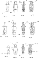
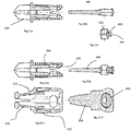
- Figure 1 shows the entirety of a device according to the invention indicated by reference numeral 100 Connecting device.
- Figure 2 is an exploded view of the connecting device 100 in its individual parts.
- the device according to the invention consists of a hollow body 200 which forms the shell of the device in which an activation element 300 is received.
- the hollow body 200 has at least one opening on one side 201.
- These elements 200, 300 and 400 are designed to be die-cast from plastic. This allows economical and series production.
- the individual elements are standard products, they can be easily exchanged. If a single part breaks during use, it can be replaced.
- the connecting device 100 according to the invention is designed in such a way that it can be easily installed manually and / or by machine.
- This activation element 300 is inserted over one of the ends of the hollow body 200.
- the activation element 300 has an opening 301 in its interior, into which the connecting element 400 is introduced and which, in the assembled state, is aligned with the opening of the hollow body 201.
- the connecting element 400 is inserted.
- the connecting element 400 preferably has an elevation 401. This survey is rotatable with coupled to the activation element 300 and, if the connection element 400 is rotated, it is displaced in a longitudinal direction facing away from the end of the hollow body 200, in which the activation element 300 was introduced inside the hollow body 200.
- the lateral opening 201 of the hollow body 200 can advantageously be an elliptical opening in one embodiment. In this way, it is possible to introduce the connecting element 400 with its projection 401 through the lateral opening 201 by connecting the activation element 300 to the hollow body 200.
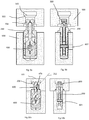
- a receptacle 501 is made, which has a recess.
- a second receptacle 601 is formed, which advantageously has a cross section in the shape of a double circle.
- a recess is also formed in the first receptacle 501 to receive the annular bead 211, which is formed outside the hollow body 200 and is a stop to the depth of the insertion of the connecting device 100 in the first receptacle 501 and / or in the second Limit inclusion 601.
- the recess in the first receptacle 501 is advantageously designed to be inclined relative to the bottom of the recess 501.
- the second end 208 of the connecting device 100 is inserted into the second receptacle 601. Thanks to the cross-sectional shape with a double circle, the connecting device is automatically centered on the lateral opening 602 of the second receptacle 601.
- the annular bead rests on the second receptacle 601 in such a way that the insertion depth of the second end of the connecting device 100 is limited.
- the first end 206 of the connecting device 100 is introduced into the first receptacle 501.
- the activation element 300 is moved by rotating the connecting element 400. This activation takes place via the lateral bore 602.
- the connecting element 400 By rotating the connecting element 400 and in particular via the projection 401 of the connecting element 400, the activation element 300 is moved within the hollow body 200 in the longitudinal direction. As it moves, the activating element pushes the shoulders 203 outward by moving the head of the end 204. With the advancement of the activation element 300, the second end 208 is also spread apart. This spreading movement is facilitated by the openings 205 provided on the hollow body 200.
- the cross-shaped end structure of the activation element allows the hollow body 200 to be spread open in all directions.
- the wings arranged on the outer surface of the hollow body 200 thus generate greater friction with the surface of the receptacle 601 and prevent the second end 208 of the hollow body 200 from pulling out of the receptacle 601 of the second component 600.
- the feed movement within the hollow body 200 the activation element 300 also spread the wings 202, which they also counteract an extension of the second end from the second receptacle 601. With the advance of the activation element 300, the tip of the activation element 300 also spreads the first end 206.
- the inclined surface 204 of the connecting device 100 according to the invention rests on the, preferably, inclined surface 502 of the receptacle 501.
- the connecting device 100 With the advancement of the activation element 300 and the bearing of the inclined surface of the hollow body 204 against the inclined surface of the receptacle 502, the connecting device 100 shortens the distance between the first component and the second component and in this way provides a connection between the two components with a minimum gap between the parts.
- the outer surface of the hollow body 200 has wings 207. These wings 207 make it more difficult to pull them out of the second receptacle 601 of the second component.
- the first end advantageously has a groove 210 at the base of the shoulders 203, which allows the shoulders 203 to spread more easily.
- the first end 206 also advantageously has two or three shoulders 203.
- the first end can have one or more side guides 213. This or these side guides are used to center the second end within the first receptacle 501.
- the connecting element 400 has an opening 402 with walls that taper from the outside to the inside by reducing the size of the opening in the center of the connecting element 400. This makes it easier to use a tool because it is centered in opening 402.
- the connecting element 400 is snapped into a receptacle at the beginning and at the end of the barrel in order to give the user a wink.
- the device according to the invention can consist entirely of plastic, which allows easy and quick assembly and economical series production.
Landscapes
- Engineering & Computer Science (AREA)
- General Engineering & Computer Science (AREA)
- Mechanical Engineering (AREA)
- Connection Of Plates (AREA)
- Threshing Machine Elements (AREA)
Applications Claiming Priority (1)
| Application Number | Priority Date | Filing Date | Title |
|---|---|---|---|
| IT102019000012105A IT201900012105A1 (it) | 2019-07-17 | 2019-07-17 | Dispositivo di giunzione in particolare per mobili |
Publications (2)
| Publication Number | Publication Date |
|---|---|
| EP3766384A1 true EP3766384A1 (fr) | 2021-01-20 |
| EP3766384B1 EP3766384B1 (fr) | 2022-03-09 |
Family
ID=68582194
Family Applications (1)
| Application Number | Title | Priority Date | Filing Date |
|---|---|---|---|
| EP20186144.0A Active EP3766384B1 (fr) | 2019-07-17 | 2020-07-16 | Dispositif de connexion, notamment pour les meubles |
Country Status (2)
| Country | Link |
|---|---|
| EP (1) | EP3766384B1 (fr) |
| IT (1) | IT201900012105A1 (fr) |
Cited By (2)
| Publication number | Priority date | Publication date | Assignee | Title |
|---|---|---|---|---|
| EP4118346A1 (fr) * | 2020-03-10 | 2023-01-18 | Effegi Brevetti S.r.l. | Dispositif d'assemblage amélioré pour parties de meubles et accessoires d'ameublement |
| EP4650609A1 (fr) * | 2024-05-15 | 2025-11-19 | Festool GmbH | Connecteur pour relier mécaniquement une première pièce à travailler et une seconde pièce à travailler, ensemble et procédé de fonctionnement d'un connecteur |
Citations (4)
| Publication number | Priority date | Publication date | Assignee | Title |
|---|---|---|---|---|
| EP0930436A1 (fr) * | 1998-01-19 | 1999-07-21 | Fiorello Giovannetti | Dispositif d'assemblage déblocable pour panneaux |
| SE1300329A1 (sv) | 2013-05-10 | 2014-11-11 | Furnparts Ab | Anordning för lösbart sammanfästande av möbeldelar såsom skivor |
| EP3302175A1 (fr) | 2015-06-08 | 2018-04-11 | CAR S.r.l. | Dispositif de raccordement entre des éléments d'un meuble |
| EP3502491A1 (fr) | 2017-12-21 | 2019-06-26 | CAR S.r.l. | Dispositif de connexion |
-
2019
- 2019-07-17 IT IT102019000012105A patent/IT201900012105A1/it unknown
-
2020
- 2020-07-16 EP EP20186144.0A patent/EP3766384B1/fr active Active
Patent Citations (4)
| Publication number | Priority date | Publication date | Assignee | Title |
|---|---|---|---|---|
| EP0930436A1 (fr) * | 1998-01-19 | 1999-07-21 | Fiorello Giovannetti | Dispositif d'assemblage déblocable pour panneaux |
| SE1300329A1 (sv) | 2013-05-10 | 2014-11-11 | Furnparts Ab | Anordning för lösbart sammanfästande av möbeldelar såsom skivor |
| EP3302175A1 (fr) | 2015-06-08 | 2018-04-11 | CAR S.r.l. | Dispositif de raccordement entre des éléments d'un meuble |
| EP3502491A1 (fr) | 2017-12-21 | 2019-06-26 | CAR S.r.l. | Dispositif de connexion |
Cited By (3)
| Publication number | Priority date | Publication date | Assignee | Title |
|---|---|---|---|---|
| EP4118346A1 (fr) * | 2020-03-10 | 2023-01-18 | Effegi Brevetti S.r.l. | Dispositif d'assemblage amélioré pour parties de meubles et accessoires d'ameublement |
| EP4118346B1 (fr) * | 2020-03-10 | 2025-05-21 | Effegi Brevetti S.r.l. | Dispositif d'assemblage amélioré pour parties de meubles et accessoires d'ameublement |
| EP4650609A1 (fr) * | 2024-05-15 | 2025-11-19 | Festool GmbH | Connecteur pour relier mécaniquement une première pièce à travailler et une seconde pièce à travailler, ensemble et procédé de fonctionnement d'un connecteur |
Also Published As
| Publication number | Publication date |
|---|---|
| EP3766384B1 (fr) | 2022-03-09 |
| IT201900012105A1 (it) | 2021-01-17 |
Similar Documents
| Publication | Publication Date | Title |
|---|---|---|
| DE60208218T2 (de) | Vorrichtung und verfahren zur lösbaren verbindung aneinanderstossender lasttragender teile und zugglied zur verwendung zur herstellung der vorrichtung | |
| DE19881663C2 (de) | Vorrichtung zur Herstellung einer Verbindung | |
| EP2786026A1 (fr) | Barre profilée, assemblage de profilés et procédé de fabrication d'un assemblage de profilés | |
| DE202016008130U1 (de) | Verbindungsvorrichtung zwischen den Komponenten eines Möbels | |
| EP0370172B1 (fr) | Dispositif de réglage en hauteur échelonné pour ferrure de fixation ou de renvoi d'une ceinture de sécurité ou équivalent | |
| EP3060823B2 (fr) | Procédé de fabrication d'un corps support comportant une masse antivibratoire pour modifier l'oscillation pour une garniture de frein d'un frein à disque | |
| DE112017006304T5 (de) | Seitlich aktivierter modularer bohrer | |
| EP2450492A1 (fr) | Système de fixation d'un article sanitaire | |
| DE102019116160A1 (de) | Seitlich geschlossener modularer Bohrer mit federunterstütztem Auswurf | |
| DE2917611A1 (de) | Duebel, werkzeug und verfahren zum herstellen einer bohrung fuer den duebel und werkzeug zum einsetzen des duebels | |
| EP3766384B1 (fr) | Dispositif de connexion, notamment pour les meubles | |
| DE3329047C2 (de) | Verfahren zum Herstellen eines Spreizdübels | |
| DE2646007A1 (de) | Verankerungsduebel | |
| DE2361846A1 (de) | Vorrichtung zur verriegelung eines elements in einer erforderlichen gebrauchsstellung | |
| DE102017121382A1 (de) | Blendenträger und Schubkasten | |
| AT524730B1 (de) | Wandbauteil für eine Schublade, Schublade und Möbel | |
| EP1455096A2 (fr) | Fixation par une sorte d'effet spirale entre cloisons et/ou étagères de meubles | |
| DE102008018692B3 (de) | Eckverbindung für Bettgestelle, die insbesondere metallfrei sind | |
| DE2627650A1 (de) | Befestigungssatz mit spreizduebel und befestigungsschraube | |
| EP2740947B1 (fr) | Système de fixation avec disque de maintien pouvant être découplé | |
| DE2731761B2 (de) | Hohlraumbefestigung | |
| DE202012104972U1 (de) | Ankerverbinder | |
| EP2802432B1 (fr) | Outil de réalisation d'une contre-dépouille annulaire dans un corps, procédé de fixation d'une cheville dans un corps, cheville à insérer dans un perçage et utilisation d'une cheville | |
| DE3328232C2 (de) | Raumfachwerk | |
| DE2650713A1 (de) | Spreizbolzen |
Legal Events
| Date | Code | Title | Description |
|---|---|---|---|
| PUAI | Public reference made under article 153(3) epc to a published international application that has entered the european phase |
Free format text: ORIGINAL CODE: 0009012 |
|
| STAA | Information on the status of an ep patent application or granted ep patent |
Free format text: STATUS: THE APPLICATION HAS BEEN PUBLISHED |
|
| AK | Designated contracting states |
Kind code of ref document: A1 Designated state(s): AL AT BE BG CH CY CZ DE DK EE ES FI FR GB GR HR HU IE IS IT LI LT LU LV MC MK MT NL NO PL PT RO RS SE SI SK SM TR |
|
| AX | Request for extension of the european patent |
Extension state: BA ME |
|
| STAA | Information on the status of an ep patent application or granted ep patent |
Free format text: STATUS: REQUEST FOR EXAMINATION WAS MADE |
|
| 17P | Request for examination filed |
Effective date: 20210416 |
|
| RBV | Designated contracting states (corrected) |
Designated state(s): AL AT BE BG CH CY CZ DE DK EE ES FI FR GB GR HR HU IE IS IT LI LT LU LV MC MK MT NL NO PL PT RO RS SE SI SK SM TR |
|
| GRAP | Despatch of communication of intention to grant a patent |
Free format text: ORIGINAL CODE: EPIDOSNIGR1 |
|
| STAA | Information on the status of an ep patent application or granted ep patent |
Free format text: STATUS: GRANT OF PATENT IS INTENDED |
|
| INTG | Intention to grant announced |
Effective date: 20211022 |
|
| GRAS | Grant fee paid |
Free format text: ORIGINAL CODE: EPIDOSNIGR3 |
|
| GRAA | (expected) grant |
Free format text: ORIGINAL CODE: 0009210 |
|
| STAA | Information on the status of an ep patent application or granted ep patent |
Free format text: STATUS: THE PATENT HAS BEEN GRANTED |
|
| AK | Designated contracting states |
Kind code of ref document: B1 Designated state(s): AL AT BE BG CH CY CZ DE DK EE ES FI FR GB GR HR HU IE IS IT LI LT LU LV MC MK MT NL NO PL PT RO RS SE SI SK SM TR |
|
| REG | Reference to a national code |
Ref country code: CH Ref legal event code: EP Ref country code: AT Ref legal event code: REF Ref document number: 1473439 Country of ref document: AT Kind code of ref document: T Effective date: 20220315 |
|
| REG | Reference to a national code |
Ref country code: DE Ref legal event code: R096 Ref document number: 502020000775 Country of ref document: DE |
|
| REG | Reference to a national code |
Ref country code: IE Ref legal event code: FG4D Free format text: LANGUAGE OF EP DOCUMENT: GERMAN |
|
| REG | Reference to a national code |
Ref country code: LT Ref legal event code: MG9D |
|
| REG | Reference to a national code |
Ref country code: NL Ref legal event code: MP Effective date: 20220309 |
|
| PG25 | Lapsed in a contracting state [announced via postgrant information from national office to epo] |
Ref country code: SE Free format text: LAPSE BECAUSE OF FAILURE TO SUBMIT A TRANSLATION OF THE DESCRIPTION OR TO PAY THE FEE WITHIN THE PRESCRIBED TIME-LIMIT Effective date: 20220309 Ref country code: RS Free format text: LAPSE BECAUSE OF FAILURE TO SUBMIT A TRANSLATION OF THE DESCRIPTION OR TO PAY THE FEE WITHIN THE PRESCRIBED TIME-LIMIT Effective date: 20220309 Ref country code: NO Free format text: LAPSE BECAUSE OF FAILURE TO SUBMIT A TRANSLATION OF THE DESCRIPTION OR TO PAY THE FEE WITHIN THE PRESCRIBED TIME-LIMIT Effective date: 20220609 Ref country code: LT Free format text: LAPSE BECAUSE OF FAILURE TO SUBMIT A TRANSLATION OF THE DESCRIPTION OR TO PAY THE FEE WITHIN THE PRESCRIBED TIME-LIMIT Effective date: 20220309 Ref country code: HR Free format text: LAPSE BECAUSE OF FAILURE TO SUBMIT A TRANSLATION OF THE DESCRIPTION OR TO PAY THE FEE WITHIN THE PRESCRIBED TIME-LIMIT Effective date: 20220309 Ref country code: BG Free format text: LAPSE BECAUSE OF FAILURE TO SUBMIT A TRANSLATION OF THE DESCRIPTION OR TO PAY THE FEE WITHIN THE PRESCRIBED TIME-LIMIT Effective date: 20220609 |
|
| PG25 | Lapsed in a contracting state [announced via postgrant information from national office to epo] |
Ref country code: LV Free format text: LAPSE BECAUSE OF FAILURE TO SUBMIT A TRANSLATION OF THE DESCRIPTION OR TO PAY THE FEE WITHIN THE PRESCRIBED TIME-LIMIT Effective date: 20220309 Ref country code: GR Free format text: LAPSE BECAUSE OF FAILURE TO SUBMIT A TRANSLATION OF THE DESCRIPTION OR TO PAY THE FEE WITHIN THE PRESCRIBED TIME-LIMIT Effective date: 20220610 Ref country code: FI Free format text: LAPSE BECAUSE OF FAILURE TO SUBMIT A TRANSLATION OF THE DESCRIPTION OR TO PAY THE FEE WITHIN THE PRESCRIBED TIME-LIMIT Effective date: 20220309 |
|
| PG25 | Lapsed in a contracting state [announced via postgrant information from national office to epo] |
Ref country code: NL Free format text: LAPSE BECAUSE OF FAILURE TO SUBMIT A TRANSLATION OF THE DESCRIPTION OR TO PAY THE FEE WITHIN THE PRESCRIBED TIME-LIMIT Effective date: 20220309 |
|
| PG25 | Lapsed in a contracting state [announced via postgrant information from national office to epo] |
Ref country code: SM Free format text: LAPSE BECAUSE OF FAILURE TO SUBMIT A TRANSLATION OF THE DESCRIPTION OR TO PAY THE FEE WITHIN THE PRESCRIBED TIME-LIMIT Effective date: 20220309 Ref country code: SK Free format text: LAPSE BECAUSE OF FAILURE TO SUBMIT A TRANSLATION OF THE DESCRIPTION OR TO PAY THE FEE WITHIN THE PRESCRIBED TIME-LIMIT Effective date: 20220309 Ref country code: RO Free format text: LAPSE BECAUSE OF FAILURE TO SUBMIT A TRANSLATION OF THE DESCRIPTION OR TO PAY THE FEE WITHIN THE PRESCRIBED TIME-LIMIT Effective date: 20220309 Ref country code: PT Free format text: LAPSE BECAUSE OF FAILURE TO SUBMIT A TRANSLATION OF THE DESCRIPTION OR TO PAY THE FEE WITHIN THE PRESCRIBED TIME-LIMIT Effective date: 20220711 Ref country code: ES Free format text: LAPSE BECAUSE OF FAILURE TO SUBMIT A TRANSLATION OF THE DESCRIPTION OR TO PAY THE FEE WITHIN THE PRESCRIBED TIME-LIMIT Effective date: 20220309 Ref country code: EE Free format text: LAPSE BECAUSE OF FAILURE TO SUBMIT A TRANSLATION OF THE DESCRIPTION OR TO PAY THE FEE WITHIN THE PRESCRIBED TIME-LIMIT Effective date: 20220309 Ref country code: CZ Free format text: LAPSE BECAUSE OF FAILURE TO SUBMIT A TRANSLATION OF THE DESCRIPTION OR TO PAY THE FEE WITHIN THE PRESCRIBED TIME-LIMIT Effective date: 20220309 |
|
| PG25 | Lapsed in a contracting state [announced via postgrant information from national office to epo] |
Ref country code: PL Free format text: LAPSE BECAUSE OF FAILURE TO SUBMIT A TRANSLATION OF THE DESCRIPTION OR TO PAY THE FEE WITHIN THE PRESCRIBED TIME-LIMIT Effective date: 20220309 Ref country code: IS Free format text: LAPSE BECAUSE OF FAILURE TO SUBMIT A TRANSLATION OF THE DESCRIPTION OR TO PAY THE FEE WITHIN THE PRESCRIBED TIME-LIMIT Effective date: 20220709 Ref country code: AL Free format text: LAPSE BECAUSE OF FAILURE TO SUBMIT A TRANSLATION OF THE DESCRIPTION OR TO PAY THE FEE WITHIN THE PRESCRIBED TIME-LIMIT Effective date: 20220309 |
|
| REG | Reference to a national code |
Ref country code: DE Ref legal event code: R097 Ref document number: 502020000775 Country of ref document: DE |
|
| PLBE | No opposition filed within time limit |
Free format text: ORIGINAL CODE: 0009261 |
|
| STAA | Information on the status of an ep patent application or granted ep patent |
Free format text: STATUS: NO OPPOSITION FILED WITHIN TIME LIMIT |
|
| PG25 | Lapsed in a contracting state [announced via postgrant information from national office to epo] |
Ref country code: DK Free format text: LAPSE BECAUSE OF FAILURE TO SUBMIT A TRANSLATION OF THE DESCRIPTION OR TO PAY THE FEE WITHIN THE PRESCRIBED TIME-LIMIT Effective date: 20220309 |
|
| 26N | No opposition filed |
Effective date: 20221212 |
|
| PG25 | Lapsed in a contracting state [announced via postgrant information from national office to epo] |
Ref country code: SI Free format text: LAPSE BECAUSE OF FAILURE TO SUBMIT A TRANSLATION OF THE DESCRIPTION OR TO PAY THE FEE WITHIN THE PRESCRIBED TIME-LIMIT Effective date: 20220309 Ref country code: MC Free format text: LAPSE BECAUSE OF FAILURE TO SUBMIT A TRANSLATION OF THE DESCRIPTION OR TO PAY THE FEE WITHIN THE PRESCRIBED TIME-LIMIT Effective date: 20220309 |
|
| REG | Reference to a national code |
Ref country code: BE Ref legal event code: MM Effective date: 20220731 |
|
| PG25 | Lapsed in a contracting state [announced via postgrant information from national office to epo] |
Ref country code: LU Free format text: LAPSE BECAUSE OF NON-PAYMENT OF DUE FEES Effective date: 20220716 Ref country code: FR Free format text: LAPSE BECAUSE OF NON-PAYMENT OF DUE FEES Effective date: 20220731 |
|
| PG25 | Lapsed in a contracting state [announced via postgrant information from national office to epo] |
Ref country code: BE Free format text: LAPSE BECAUSE OF NON-PAYMENT OF DUE FEES Effective date: 20220731 |
|
| PG25 | Lapsed in a contracting state [announced via postgrant information from national office to epo] |
Ref country code: IE Free format text: LAPSE BECAUSE OF NON-PAYMENT OF DUE FEES Effective date: 20220716 |
|
| PG25 | Lapsed in a contracting state [announced via postgrant information from national office to epo] |
Ref country code: MK Free format text: LAPSE BECAUSE OF FAILURE TO SUBMIT A TRANSLATION OF THE DESCRIPTION OR TO PAY THE FEE WITHIN THE PRESCRIBED TIME-LIMIT Effective date: 20220309 Ref country code: CY Free format text: LAPSE BECAUSE OF FAILURE TO SUBMIT A TRANSLATION OF THE DESCRIPTION OR TO PAY THE FEE WITHIN THE PRESCRIBED TIME-LIMIT Effective date: 20220309 |
|
| PG25 | Lapsed in a contracting state [announced via postgrant information from national office to epo] |
Ref country code: HU Free format text: LAPSE BECAUSE OF FAILURE TO SUBMIT A TRANSLATION OF THE DESCRIPTION OR TO PAY THE FEE WITHIN THE PRESCRIBED TIME-LIMIT; INVALID AB INITIO Effective date: 20200716 |
|
| PG25 | Lapsed in a contracting state [announced via postgrant information from national office to epo] |
Ref country code: MT Free format text: LAPSE BECAUSE OF FAILURE TO SUBMIT A TRANSLATION OF THE DESCRIPTION OR TO PAY THE FEE WITHIN THE PRESCRIBED TIME-LIMIT Effective date: 20220309 |
|
| GBPC | Gb: european patent ceased through non-payment of renewal fee |
Effective date: 20240716 |
|
| PG25 | Lapsed in a contracting state [announced via postgrant information from national office to epo] |
Ref country code: GB Free format text: LAPSE BECAUSE OF NON-PAYMENT OF DUE FEES Effective date: 20240716 |
|
| PGFP | Annual fee paid to national office [announced via postgrant information from national office to epo] |
Ref country code: DE Payment date: 20250729 Year of fee payment: 6 |
|
| PGFP | Annual fee paid to national office [announced via postgrant information from national office to epo] |
Ref country code: IT Payment date: 20250722 Year of fee payment: 6 |
|
| PGFP | Annual fee paid to national office [announced via postgrant information from national office to epo] |
Ref country code: AT Payment date: 20250702 Year of fee payment: 6 |
|
| PGFP | Annual fee paid to national office [announced via postgrant information from national office to epo] |
Ref country code: CH Payment date: 20250801 Year of fee payment: 6 |
|
| PG25 | Lapsed in a contracting state [announced via postgrant information from national office to epo] |
Ref country code: TR Free format text: LAPSE BECAUSE OF FAILURE TO SUBMIT A TRANSLATION OF THE DESCRIPTION OR TO PAY THE FEE WITHIN THE PRESCRIBED TIME-LIMIT Effective date: 20220309 |