EP3766744A1 - Déclenchement d'au moins un coussin gonflable d'un véhicule sans équipage - Google Patents
Déclenchement d'au moins un coussin gonflable d'un véhicule sans équipage Download PDFInfo
- Publication number
- EP3766744A1 EP3766744A1 EP20184164.0A EP20184164A EP3766744A1 EP 3766744 A1 EP3766744 A1 EP 3766744A1 EP 20184164 A EP20184164 A EP 20184164A EP 3766744 A1 EP3766744 A1 EP 3766744A1
- Authority
- EP
- European Patent Office
- Prior art keywords
- unmanned vehicle
- triggering
- parameter
- vehicle
- sensor
- Prior art date
- Legal status (The legal status is an assumption and is not a legal conclusion. Google has not performed a legal analysis and makes no representation as to the accuracy of the status listed.)
- Granted
Links
Images

Classifications
-
- B—PERFORMING OPERATIONS; TRANSPORTING
- B60—VEHICLES IN GENERAL
- B60R—VEHICLES, VEHICLE FITTINGS, OR VEHICLE PARTS, NOT OTHERWISE PROVIDED FOR
- B60R21/00—Arrangements or fittings on vehicles for protecting or preventing injuries to occupants or pedestrians in case of accidents or other traffic risks
- B60R21/01—Electrical circuits for triggering passive safety arrangements, e.g. airbags, safety belt tighteners, in case of vehicle accidents or impending vehicle accidents
- B60R21/013—Electrical circuits for triggering passive safety arrangements, e.g. airbags, safety belt tighteners, in case of vehicle accidents or impending vehicle accidents including means for detecting collisions, impending collisions or roll-over
- B60R21/0134—Electrical circuits for triggering passive safety arrangements, e.g. airbags, safety belt tighteners, in case of vehicle accidents or impending vehicle accidents including means for detecting collisions, impending collisions or roll-over responsive to imminent contact with an obstacle, e.g. using radar systems
-
- B—PERFORMING OPERATIONS; TRANSPORTING
- B60—VEHICLES IN GENERAL
- B60R—VEHICLES, VEHICLE FITTINGS, OR VEHICLE PARTS, NOT OTHERWISE PROVIDED FOR
- B60R21/00—Arrangements or fittings on vehicles for protecting or preventing injuries to occupants or pedestrians in case of accidents or other traffic risks
- B60R21/34—Protecting non-occupants of a vehicle, e.g. pedestrians
- B60R21/36—Protecting non-occupants of a vehicle, e.g. pedestrians using airbags
-
- G—PHYSICS
- G08—SIGNALLING
- G08G—TRAFFIC CONTROL SYSTEMS
- G08G1/00—Traffic control systems for road vehicles
- G08G1/16—Anti-collision systems
- G08G1/161—Decentralised systems, e.g. inter-vehicle communication
- G08G1/163—Decentralised systems, e.g. inter-vehicle communication involving continuous checking
-
- G—PHYSICS
- G08—SIGNALLING
- G08G—TRAFFIC CONTROL SYSTEMS
- G08G1/00—Traffic control systems for road vehicles
- G08G1/16—Anti-collision systems
- G08G1/166—Anti-collision systems for active traffic, e.g. moving vehicles, pedestrians, bikes
-
- B—PERFORMING OPERATIONS; TRANSPORTING
- B60—VEHICLES IN GENERAL
- B60R—VEHICLES, VEHICLE FITTINGS, OR VEHICLE PARTS, NOT OTHERWISE PROVIDED FOR
- B60R21/00—Arrangements or fittings on vehicles for protecting or preventing injuries to occupants or pedestrians in case of accidents or other traffic risks
- B60R21/01—Electrical circuits for triggering passive safety arrangements, e.g. airbags, safety belt tighteners, in case of vehicle accidents or impending vehicle accidents
- B60R2021/01013—Means for detecting collision, impending collision or roll-over
-
- B—PERFORMING OPERATIONS; TRANSPORTING
- B60—VEHICLES IN GENERAL
- B60R—VEHICLES, VEHICLE FITTINGS, OR VEHICLE PARTS, NOT OTHERWISE PROVIDED FOR
- B60R21/00—Arrangements or fittings on vehicles for protecting or preventing injuries to occupants or pedestrians in case of accidents or other traffic risks
- B60R21/01—Electrical circuits for triggering passive safety arrangements, e.g. airbags, safety belt tighteners, in case of vehicle accidents or impending vehicle accidents
- B60R2021/01204—Actuation parameters of safety arrangents
- B60R2021/01211—Expansion of air bags
-
- B—PERFORMING OPERATIONS; TRANSPORTING
- B60—VEHICLES IN GENERAL
- B60R—VEHICLES, VEHICLE FITTINGS, OR VEHICLE PARTS, NOT OTHERWISE PROVIDED FOR
- B60R21/00—Arrangements or fittings on vehicles for protecting or preventing injuries to occupants or pedestrians in case of accidents or other traffic risks
- B60R21/01—Electrical circuits for triggering passive safety arrangements, e.g. airbags, safety belt tighteners, in case of vehicle accidents or impending vehicle accidents
- B60R2021/01204—Actuation parameters of safety arrangents
- B60R2021/01211—Expansion of air bags
- B60R2021/01218—Expansion of air bags control of expansion speed
-
- B—PERFORMING OPERATIONS; TRANSPORTING
- B60—VEHICLES IN GENERAL
- B60R—VEHICLES, VEHICLE FITTINGS, OR VEHICLE PARTS, NOT OTHERWISE PROVIDED FOR
- B60R21/00—Arrangements or fittings on vehicles for protecting or preventing injuries to occupants or pedestrians in case of accidents or other traffic risks
- B60R21/01—Electrical circuits for triggering passive safety arrangements, e.g. airbags, safety belt tighteners, in case of vehicle accidents or impending vehicle accidents
- B60R2021/01204—Actuation parameters of safety arrangents
- B60R2021/01211—Expansion of air bags
- B60R2021/01225—Expansion of air bags control of expansion volume
-
- B—PERFORMING OPERATIONS; TRANSPORTING
- B60—VEHICLES IN GENERAL
- B60R—VEHICLES, VEHICLE FITTINGS, OR VEHICLE PARTS, NOT OTHERWISE PROVIDED FOR
- B60R21/00—Arrangements or fittings on vehicles for protecting or preventing injuries to occupants or pedestrians in case of accidents or other traffic risks
- B60R21/01—Electrical circuits for triggering passive safety arrangements, e.g. airbags, safety belt tighteners, in case of vehicle accidents or impending vehicle accidents
- B60R2021/01204—Actuation parameters of safety arrangents
- B60R2021/01211—Expansion of air bags
- B60R2021/01231—Expansion of air bags control of expansion timing or sequence
-
- B—PERFORMING OPERATIONS; TRANSPORTING
- B60—VEHICLES IN GENERAL
- B60R—VEHICLES, VEHICLE FITTINGS, OR VEHICLE PARTS, NOT OTHERWISE PROVIDED FOR
- B60R21/00—Arrangements or fittings on vehicles for protecting or preventing injuries to occupants or pedestrians in case of accidents or other traffic risks
- B60R21/01—Electrical circuits for triggering passive safety arrangements, e.g. airbags, safety belt tighteners, in case of vehicle accidents or impending vehicle accidents
- B60R2021/01286—Electronic control units
-
- B—PERFORMING OPERATIONS; TRANSPORTING
- B60—VEHICLES IN GENERAL
- B60R—VEHICLES, VEHICLE FITTINGS, OR VEHICLE PARTS, NOT OTHERWISE PROVIDED FOR
- B60R21/00—Arrangements or fittings on vehicles for protecting or preventing injuries to occupants or pedestrians in case of accidents or other traffic risks
- B60R21/01—Electrical circuits for triggering passive safety arrangements, e.g. airbags, safety belt tighteners, in case of vehicle accidents or impending vehicle accidents
- B60R21/013—Electrical circuits for triggering passive safety arrangements, e.g. airbags, safety belt tighteners, in case of vehicle accidents or impending vehicle accidents including means for detecting collisions, impending collisions or roll-over
- B60R21/0134—Electrical circuits for triggering passive safety arrangements, e.g. airbags, safety belt tighteners, in case of vehicle accidents or impending vehicle accidents including means for detecting collisions, impending collisions or roll-over responsive to imminent contact with an obstacle, e.g. using radar systems
- B60R2021/01345—Electrical circuits for triggering passive safety arrangements, e.g. airbags, safety belt tighteners, in case of vehicle accidents or impending vehicle accidents including means for detecting collisions, impending collisions or roll-over responsive to imminent contact with an obstacle, e.g. using radar systems using mechanical sensing means
Definitions
- Exemplary embodiments of the invention relate to a method, a device and a computer program for triggering at least one impact cushion for an unmanned vehicle.
- unmanned vehicles with a means for picking up and transporting one or more shipments are known.
- Such an unmanned vehicle moves autonomously or partially autonomously (e.g. in a follow-me mode behind a person or by remote control) on sidewalks, bike paths and streets. It crosses streets, pulls out from behind house corners or turns around bends.
- the unmanned vehicle e.g. compared to a person walking upright
- it is easily overlooked by other road users, e.g. pedestrians or cyclists.
- the present invention has therefore set itself the task of providing a method, a device, a system and a computer program for triggering at least one impact cushion of an unmanned vehicle.
- the disclosed method is carried out by an apparatus, for example the apparatus disclosed below.
- a device comprising means set up for carrying out the disclosed method or respective means for carrying out the steps of the disclosed method.
- One or more steps can be carried out by the same means or different steps by different means.
- the means of the disclosed device can comprise hardware and / or software components.
- the means can comprise, for example, at least one memory with program instructions of a computer program (e.g. the computer program disclosed below) and at least one processor designed to execute program instructions from the at least one memory.
- a device should also be understood as disclosed which comprises at least one processor and at least one memory with program instructions, the at least one memory and the program instructions being set up, together with the at least one processor, to cause the device to execute the disclosed method and / or control.
- the means of the device can, for example, also include one or more wireless and / or wired communication interfaces (for example one or more wireless and / or wired network adapters) and / or one or more User interfaces (e.g., a keyboard, a mouse, a monitor, a touch screen, a speaker, a microphone, a camera, etc.).
- one or more wireless and / or wired communication interfaces for example one or more wireless and / or wired network adapters
- User interfaces e.g., a keyboard, a mouse, a monitor, a touch screen, a speaker, a microphone, a camera, etc.
- the device further comprises at least one sensor that is set up to detect sensor information.
- the device is set up, for example, to receive sensor information from one or more sensors of the unmanned vehicle.
- the sensors of the unmanned vehicle are external to the device (i.e. not part of the device).
- the device is communicatively connected directly or indirectly to the sensors of the unmanned vehicle.
- An example of such a sensor is an environment sensor that is set up to at least partially monitor an environment of the unmanned vehicle and sensor information (e.g. sensor information that contains at least one object parameter of an object that moves with respect to the unmanned vehicle and in which Environment of the unmanned vehicle is represented).
- a vehicle sensor which is set up to detect vehicle information that represents a vehicle parameter (e.g. an acceleration or speed) of the unmanned vehicle.
- the device is communicatively connected, for example, directly or indirectly to at least one impact cushion of the unmanned vehicle, so that the device can, for example, trigger the at least one impact cushion.
- the disclosed device is communicatively connected, for example, to a sensor (e.g. an object sensor or a vehicle sensor) and an impact cushion of the unmanned vehicle
- a sensor e.g. an object sensor or a vehicle sensor
- an impact cushion of the unmanned vehicle can be understood, for example, to mean that the connection between the device and the respective component (i.e. sensor and / or Impact cushion) is a wired and / or wireless communication link (e.g. for information transmission).
- the device comprises, for example, one or more wireless and / or wired communication interfaces (for example one or more wireless and / or wired network adapters).
- the device may comprise one or more user interfaces (e.g. a keyboard, a mouse, a screen, a touch-sensitive screen, a loudspeaker, a microphone, a camera, etc.).
- user interfaces e.g. a keyboard, a mouse, a screen, a touch-sensitive screen, a loudspeaker, a microphone, a camera, etc.
- the device is a device for the unmanned vehicle, or a module for the unmanned vehicle, or a part of the unmanned vehicle, for example in that the device is installed in the unmanned vehicle.
- the device can, for example, be a control device or a control module for the unmanned vehicle.
- the device can, for example, be connected to the power supply of the unmanned vehicle.
- the device can also have its own power supply in the form of its own energy store such as a battery and / or a capacitor.
- the device's own energy supply could serve as a backup power supply, for example. In this way, the device can be operated even if the power supply to the unmanned vehicle fails.
- the device as part of the unmanned vehicle, it is also possible, for example, to deactivate the device (e.g. manually or automatically) and to use the unmanned vehicle independently of the disclosed use of the device. This is advantageous, for example, in situations in which method steps carried out by the device, in particular the triggering of an impact cushion, are not desired.
- the device is a server, for example a server remote from the unmanned vehicle (ie a server that is not part of the unmanned vehicle).
- a server can be, for example, both a physical server (ie a server with hardware and / or software components) and a virtual server.
- a virtual server should be understood to mean, for example, a server functionality provided by hardware and / or software components of one or more physical servers (e.g. several servers of a so-called server cloud), in that the several physical servers interact, for example, to provide the functionality of the virtual server .
- a computer program is further disclosed, the computer program comprising program instructions which, when executed by at least one processor, cause a device (e.g. the disclosed device) to carry out the disclosed method.
- the disclosed computer program is contained and / or stored, for example, on a computer-readable storage medium.
- a computer-readable storage medium should be understood to mean, for example, a physical and / or touchable storage medium. It goes without saying that the invention is not restricted to this and the storage medium can alternatively also be a virtual storage medium that is formed, for example, by a plurality of physical memories.
- the unmanned vehicle is to be understood as meaning, for example, a land vehicle that takes part in land traffic, in particular in pedestrian traffic or in pedestrian areas (e.g. on sidewalks, inside buildings and in pedestrian zones).
- the unmanned vehicle preferably has neither a driver nor passengers.
- the unmanned vehicle is set up to move at least partially autonomously and / or automatically and / or remotely.
- the unmanned vehicle is a robot and / or a drone.
- the unmanned vehicle includes at least the impact cushion, which is arranged, for example, on an outside of the unmanned vehicle and / or opens outwards and / or unfolds (ie opens and / or unfolds away from an outside of the unmanned vehicle) when triggered becomes.
- An impact cushion can, for example, be at least partially formed by a fluid sack which, when the impact cushion is triggered, is filled with a fluid and thereby opens and / or unfolds.
- An example of such a crash cushion is an airbag device comprising a gas bag (eg a plastic bag, in particular a nylon bag) and a gas generator, the airbag device being set up, when triggered, to fill the gas bag with gas generated by the gas generator.
- the gas generator is, for example, a pyrotechnic gas generator, a cold gas generator or a hybrid gas generator.
- a gas generator comprises an ignition unit and one or more propellant charges (for example a solid propellant which is in tablet form).
- the ignition unit ignites one or more of the propellant charges when the airbag is triggered (eg via a current pulse) so that gas is generated, which leads to the gas bag being filled with gas.
- an airbag device can be deployed with different deployment intensities. The lowest trigger intensity corresponds, for example, to the case that only one propellant charge is ignited, and the highest trigger intensity corresponds, for example, to the case that all propellant charges are ignited.
- the unmanned vehicle comprises at least one sensor which is set up to acquire sensor information (e.g. sensor information representing at least one object parameter of an object moving in relation to the unmanned vehicle or vehicle information).
- a sensor of the unmanned vehicle may be a sensor of the device or external to the device.
- the sensor of the unmanned vehicle can be a sensor of a plurality of sensors of the unmanned vehicle.
- the sensors of such a plurality of sensors can be at least partially different sensors and / or at least partially arranged at different locations (e.g. on different sides) of the unmanned vehicle.
- sensor information detected by a sensor eg the environment sensor or a vehicle sensor
- the sensor if the sensor is also part of the device, can be obtained by the device by detecting the sensor information by the at least one sensor.
- sensor information detected by a sensor for example the environment sensor or a vehicle sensor
- Sensor information can be obtained from the sensor (e.g. via a communication link) through the device.
- Effecting the receipt of sensor information detected by a sensor of the unmanned vehicle is to be understood as meaning, for example, that the device controls the unmanned vehicle and / or the sensor in such a way (e.g. by means of control information) that the unmanned vehicle and / or the sensor receives the sensor information detected and made available to the device (for example sends to the device via a communication link) so that the device receives the information.
- the device and the unmanned vehicle have, for example, appropriately set up communication interfaces.
- Sensor information detected by a sensor of the unmanned vehicle should be, for example, a quantitative or qualitative representation of a chemical or physical property detected by the sensor (e.g. in the form of a sensor information detected measured value of a chemical or physical property) and / or an environmental quality detected by the sensor (for example in the form of an image detected by an optical sensor such as a camera).
- a parameter represented by sensor information should, for example, be a qualitative or quantitative representation of a measured value of a physical and / or chemical property (e.g. a speed) detected by a sensor (e.g. an environmental sensor or a vehicle sensor) or acceleration).
- a quantitative representation of a measured value of a physical and / or chemical property can, for example, indicate the measured value of the physical and / or chemical property detected by the sensor; and a qualitative representation of a physical and / or chemical property can for example represent an indication of whether the measured value of the physical and / or chemical property recorded and / or determined by the sensor is above or below a predetermined threshold value or in a predetermined measured value range.
- a parameter represented by sensor information can also be understood as a parameter that can be determined based on the sensor information.
- the sensor information is processed further in order to obtain the parameter represented by the sensor information.
- an object recognition and object classification algorithm is applied to sensor information, which represents an image captured by an optical sensor such as a camera, in order to recognize and / or classify an object contained in the image, so that as Object parameters, for example, the object class of the recognized object is determined.
- sensor information can represent several parameters (e.g. several object parameters or vehicle parameters). It is therefore conceivable, for example, that sensor information represents the course of a parameter over time. Alternatively or additionally, one piece of sensor information can represent several different parameters. For example, it should also be understood as disclosed that a single piece of sensor information represents a minimum number of parameters (e.g. at least one parameter, at least two parameters, etc.).
- the sensor information detected by the environment sensor of the unmanned vehicle represents an object parameter of an object
- this sensor information represents a qualitative or quantitative representation of at least one measured value of at least one chemical or physical property of the object detected by the environment sensor or the object parameters of the Object can be determined based on this sensor information.
- An example of the object parameter of the object is a speed, an acceleration, an object class or a distance of the object.
- the object is, for example, a road user (for example a person and / or a vehicle) or an object in an environment (for example an environment that can be detected by the sensor of the unmanned vehicle) of the unmanned vehicle.
- a road user for example a person and / or a vehicle
- an object in an environment for example an environment that can be detected by the sensor of the unmanned vehicle
- the fact that the object moves with respect to the unmanned vehicle is to be understood, for example, in such a way that the unmanned vehicle and the object approach or move away from one another.
- the object can be moving or at rest.
- Determining whether a collision is imminent between the unmanned vehicle and the object takes place, for example, according to one or more (e.g. predetermined) rules such as an algorithm or a decision model.
- the fact that the determination of whether a collision between the unmanned vehicle and the object is imminent is based at least partially on the at least one object parameter should be understood, for example, to mean that the at least one object parameter when determining whether a collision between the unmanned vehicle and the object threatens to be taken into account.
- one or more further object parameters e.g. represented by the sensor information
- other parameters e.g. vehicle parameters of the unmanned vehicle
- the rules can specify for which object parameters (e.g. for which qualitative or quantitative representation of at least one measured value of at least one chemical or physical property of the object detected by the environmental sensor) or for which combination of object parameters that a collision between the unmanned The vehicle and the property.
- the rules can specify, for example, that if an object parameter represented by the sensor information indicates that the object is approaching the unmanned vehicle at a speed greater than or equal to a predetermined threshold value (e.g. 3 m / s) and the distance of the object to the unmanned vehicle is less than or equal to a predetermined threshold value (for example 0.3 m), a collision between the unmanned vehicle and the object threatens.
- a predetermined threshold value e.g. 3 m / s
- a collision between the unmanned vehicle and the object should be understood to mean, for example, a collision between the unmanned vehicle and the object.
- the object collided with the unmanned vehicle is, for example, a person (for example a pedestrian or a cyclist), the collision can result in injury to the person.
- the at least one triggering parameter for triggering the at least one impact cushion of the unmanned vehicle and triggering and / or causing the triggering of the at least one impact cushion is determined. It can be provided, for example, that these steps (i.e. determining the triggering parameter and triggering and / or causing the triggering of the at least one impact cushion) are only carried out if it is determined that a collision between the unmanned vehicle and the object is imminent.
- the at least one triggering parameter for triggering the at least one impact cushion is set up, for example, to at least partially control the triggering of the at least one impact cushion.
- the at least one triggering parameter specifies, for example, the at least one impact cushion, a triggering intensity, a triggering volume and / or a triggering time for triggering the at least one impact cushion.
- the at least one impact pad can be part of a plurality of impact pads.
- the at least one triggering parameter can define, for example, which triggering pad (s) of the plurality of triggering pads are to be triggered.
- the at least one triggering parameter for triggering the at least one impact cushion of the unmanned vehicle is determined, for example, in accordance with one or more (eg predetermined) rules such as an algorithm or a decision model.
- the fact that the determination of at least one trigger parameter for triggering the at least one impact cushion is based at least partially on the at least one object parameter should be understood, for example, to mean that the object information is taken into account when determining at least one trigger parameter for triggering the at least one impact cushion.
- one or more further object parameters for example represented by the sensor information
- other parameters for example vehicle parameters of the unmanned vehicle
- one or more further triggering parameters for triggering the at least one impact cushion of the unmanned vehicle can be determined.
- the rules can specify for which object parameters (e.g. for which qualitative or quantitative representation of at least one measured value of at least one chemical or physical property of the object detected by the environmental sensor) or for which combination of object parameters which trigger parameter (s) should be determined ).
- the rules can stipulate, for example, that the at least one impact cushion should be triggered with a first trigger intensity (e.g. a gas pressure with which the gas bag of an airbag device is filled with gas by the gas generator when triggered) when the at least one is triggered by the Object parameters represented by sensor information indicate that the object is approaching the unmanned vehicle at a speed less than a predetermined threshold value (e.g.
- the object parameter represented indicates that the object is approaching the unmanned vehicle at a speed greater than or equal to the predetermined threshold value (eg 5 m / s).
- the first triggering intensity is, for example, less than the second triggering intensity.
- the at least one impact cushion is triggered according to the at least one trigger parameter should be understood, for example, to mean that the at least one trigger parameter is taken into account when triggering the at least one impact cushion, for example by controlling the triggering of the at least one impact cushion in such a way that the at least one impact cushion is triggered a trip parameter is followed.
- the disclosed device controls the unmanned vehicle (e.g. a control device of the unmanned vehicle) and / or the at least one impact cushion of the unmanned vehicle in such a way (e.g. by means of control information) that the at least one impact pad is triggered.
- the impact cushion is triggered by a suitable trigger mechanism (e.g. a lighting unit).
- the at least one impact cushion of the unmanned vehicle should be triggered in such a way that the at least one impact cushion is triggered before the impending collision.
- the at least one impact cushion (1) is determined immediately (for example as quickly as possible) after that a collision is imminent, or (2) to one specific triggering time (e.g. determined by a further triggering parameter) is triggered.
- the triggering of the at least one impact cushion before the impending collision according to the at least one triggering parameter is particularly advantageous, since damage as a consequence of an impending collision for which there is an increased risk with regard to an unmanned vehicle, for example due to its small size, compared to other road users can be effectively prevented or reduced.
- the triggering of the at least one impact cushion can be particularly advantageous because the at least one impact cushion according to the at least one specific triggering parameter occurs before the impending collision between the unmanned vehicle and an object (e.g. before the physical contact between the unmanned vehicle and the object, if the impending collision actually occurs) is triggered.
- the triggering of at least one impact cushion before the impending collision can be particularly advantageous because, for example, a lower triggering intensity than conventional triggering methods (e.g. a lower speed at which the impact cushion opens) can already be sufficient to avoid collision damage protect.
- the fact that the determination of a probability for the occurrence of the impending collision is at least partially based on the at least one object parameter should be understood, for example, to mean that the at least one object parameter is taken into account when determining a probability for the occurrence of the impending collision.
- a speed of the object and / or a distance of the object from the unmanned vehicle is taken into account in order to determine a probability for the impending collision to occur.
- the higher the probability that the impending collision will occur the faster the object moves and / or the smaller the distance between the object and the unmanned vehicle.
- one or more further object parameters e.g. represented by the sensor information
- other parameters e.g. vehicle parameters of the unmanned vehicle
- Whether a collision is imminent between the unmanned vehicle and the object can accordingly include, for example, checking whether the probability determined for the impending collision to occur exceeds a predetermined threshold value (e.g. 50%, 75% or 90%).
- a predetermined threshold value e.g. 50%, 75% or 90%.
- the threshold value can, for example, have been determined by systematic experiments and / or be based on machine learning.
- the decision model receives the at least one object parameter, for example, as an input parameter and outputs a probability that a collision with the object is imminent as an output parameter.
- a decision model are an artificial neural network or an AI (artificial intelligence) based decision matrix.
- the decision model is obtained, for example, as the result of a learning phase according to a machine learning algorithm (e.g. an algorithm according to the deep learning method).
- the decision model is trained using object parameters as input parameters.
- the object parameters can be obtained, for example, in the context of systematic experiments.
- the unmanned vehicle includes a plurality of impact pads.
- One or more (e.g. each) of the impact cushions of the plurality of impact cushions can for example be arranged at a different location on an outside of the unmanned vehicle and / or at least partially open and / or unfold in a different direction when the respective impact cushion is triggered.
- the plurality of impact pads can be arranged at least partially in the form of a matrix on an outside of the unmanned vehicle. Furthermore, the majority of the impact pads can differ at least partially (e.g. in shape and / or size).
- one or more of the impact cushions of the plurality of impact cushions can be arranged on a front, rear, right and / or left outside of the unmanned vehicle as seen in the direction of travel of the unmanned vehicle and can open or unfold at least substantially away from the respective outside, so that the impact cushions of the plurality of impact cushions arranged on the front outer side of the unmanned vehicle open and / or unfold at least essentially in the direction of travel when they are triggered.
- determining whether a collision is imminent between the unmanned vehicle and the object further includes determining from which direction and / or on which outside (e.g. on the front, rear, left, right outside) of the unmanned vehicle threatens a collision with the object, for example at least partially based on the at least one object parameter (eg a direction of movement) of the object. Accordingly, if it is determined, for example, that a collision is imminent between the unmanned vehicle and the object and that this collision is imminent on a specific outside of the unmanned vehicle, it can be determined, for example, that at least one impact cushion of the plurality of impact cushions is triggered, which is on the specific Outside of the unmanned vehicle is arranged on which the collision threatens.
- This procedure is advantageous, for example, in order to specifically reduce and / or prevent collision damage due to an impending collision and to use the plurality of impact cushions particularly efficiently (e.g. by avoiding unnecessary triggering of one impact cushion of the plurality of impact cushions).
- the unmanned vehicle comprises it can be determined, for example, that more than one impact cushion (e.g. 2, 3 or more impact cushions) of the plurality of impact cushions are to be triggered. It can be determined, for example, that these multiple impact cushions are at least partially triggered according to different triggering parameters. In this way it can be achieved, for example, that the multiple impact cushions are triggered, for example, at the same time or at different times, or, for example, are triggered with the same or different triggering intensity.
- more than one impact cushion e.g. 2, 3 or more impact cushions
- a triggering parameter is obtained, for example, which defines which at least one impact cushion of the plurality of impact cushions is to be triggered.
- the triggering parameter can represent (e.g. identify) the at least one impact cushion of the plurality of impact cushions.
- the triggering parameter can furthermore define, for example, a triggering intensity, a triggering volume and / or a triggering time for triggering the at least one impact cushion.
- the at least one triggering parameter defines the at least one impact cushion, a triggering intensity, a triggering volume and / or a triggering time for triggering the at least one impact cushion.
- a trigger intensity of an impact cushion is characteristic, for example, of the period in which the impact cushion opens and / or unfolds when it is triggered, the speed at which the impact cushion opens and / or unfolds when it is triggered, and / or or the pressure with which the impact pad opens and / or deploys when triggered.
- a trigger volume of an impact cushion should be understood, for example, as the (e.g. maximum) volume of the opened and / or unfolded impact cushion after triggering.
- the trigger time of an impact cushion describes, for example, the point in time at which the impact cushion is to be triggered (e.g. the point in time at which the opening and / or unfolding of the impact cushion is to begin).
- an example of an impact cushion is an airbag device comprising a gas bag (e.g. a plastic bag, in particular a nylon bag) and a gas generator, the airbag device being set up, when triggered, to fill the gas bag with gas generated by the gas generator.
- the gas generator comprises, for example, an ignition unit and one or more propellant charges (for example a solid propellant which is in tablet form).
- the ignition unit ignites one or more of the propellant charges when the airbag is triggered (e.g. via a current pulse), so that gas is generated, which leads to the gas bag being filled with gas.
- a triggering parameter can determine the triggering intensity and / or the triggering volume of an airbag device by specifying the number of propellant charges that are to be ignited by the ignition unit.
- a triggering parameter can define the triggering time of an airbag device by specifying the point in time at which the ignition unit should ignite the propellant charge (s).
- a position of an object is, for example, an absolute position or a relative position (e.g. in relation to the unmanned vehicle).
- a position can be represented, for example, in the form of a position specification that relates, for example, to any absolute or relative coordinate system that has been specified.
- a position of an object in relation to the unmanned vehicle can, for example, be determined based on a sequence of several images captured by an optical sensor (e.g. a camera) of the unmanned vehicle.
- a distance between an object (for example the object) and the unmanned vehicle is, for example, a Euclidean or geodetic distance between the object and the unmanned vehicle.
- a distance between such an object and the unmanned vehicle can, for example, by a distance sensor (e.g. a Distance sensor in the form of an ultrasonic or radar sensor) of the unmanned vehicle can be detected.
- An object class of an object is, for example, an object class of a plurality of predetermined object classes.
- object classes are: moving objects and non-moving objects.
- Land vehicles such as bicycles, motorcycles, cars, trucks and pedestrians as object classes for "moving objects” and street furniture (e.g. bench, traffic lights, advertising column, street sign), buildings, plants as object classes for "non-moving objects”.
- a position of an object in relation to the unmanned vehicle can be determined, for example, based on an image captured by an optical sensor (e.g. a camera) of the unmanned vehicle (e.g. according to a predefined algorithm such as a predefined segmentation, image recognition and / or classification algorithm) .
- a direction of movement of an object is to be understood, for example, as the direction in which the object is moving.
- This direction can, for example, be represented without reference (e.g. by specifying a compass direction) or with reference to the unmanned vehicle (e.g. by specifying an angle which includes the direction of movement of the object with a direction of movement of the unmanned vehicle).
- the direction of movement as an object parameter of an object, is limited to an indication of whether or not the object is moving towards the unmanned vehicle.
- a speed of an object can be understood, for example, without reference (e.g. as absolute speed) or with reference to the unmanned vehicle (e.g. as relative speed or differential speed). It can also be an average speed or a current speed, for example.
- An acceleration of an object can be understood, for example, without reference (for example as an absolute acceleration) or with reference to the unmanned vehicle (for example as relative acceleration or differential acceleration).
- the acceleration of an object is a change in the Specifies the speed of the object and thus a positive acceleration (increase in the speed of the object) or a negative acceleration (decrease in the speed of the object) of the object is conceivable.
- a direction of movement, a speed and / or an acceleration of an object can be detected, for example, by a radar or lidar sensor of the unmanned vehicle.
- the at least one environmental sensor of the unmanned vehicle is one of the following sensors: a temperature sensor (e.g. a thermometer, a thermocouple and / or a thermal resistor), an electromagnetic sensor (e.g. a radar sensor), an acoustic sensor (e.g. a Microphone, a noise sensor and / or an ultrasonic sensor) or an optical sensor (e.g. an infrared sensor, a light sensor, a brightness sensor, a photodiode, a photoresistor, an image sensor, an image camera, a CMOS sensor and / or a CCD sensor, a Video camera and / or a lidar sensor).
- a temperature sensor e.g. a thermometer, a thermocouple and / or a thermal resistor
- an electromagnetic sensor e.g. a radar sensor
- an acoustic sensor e.g. a Microphone, a noise sensor and / or an ultrasonic sensor
- an optical sensor e
- vehicle information detected by the vehicle sensor of the unmanned vehicle represents a vehicle parameter of the unmanned vehicle
- vehicle information detected by the vehicle sensor of the unmanned vehicle represents a qualitative or quantitative representation of at least one measured value of at least one chemical or physical property of the unmanned vehicle detected by the vehicle sensor.
- vehicle parameter of the unmanned vehicle is a speed or an acceleration of the unmanned vehicle.
- the fact that the determination of whether a collision between the unmanned vehicle and the object is imminent is based at least partially on the at least one vehicle parameter should be understood, for example, to mean that the at least one vehicle parameter when determining whether a collision between the unmanned vehicle and the object threatens to be taken into account.
- the determination of whether a collision is imminent between the unmanned vehicle and the object can take place, for example, in accordance with one or more (e.g. predetermined) rules such as an algorithm or a decision model.
- the rules can specify for which combination of object parameter (s) and vehicle parameter (s) it should be determined that a collision between the unmanned vehicle and the object is imminent.
- the rules can stipulate, for example, that if the object parameter represented by the sensor information indicates that the distance of the object to the unmanned vehicle is less than or equal to a predetermined threshold value (e.g.
- such vehicle information which represents at least one detected vehicle parameter of the unmanned vehicle
- vehicle information can be obtained, for example, by detecting the vehicle parameter by at least one vehicle sensor of the unmanned vehicle.
- the present invention is not limited thereto. Accordingly, it should be understood as disclosed that the at least one vehicle parameter is detected by at least one vehicle sensor of the unmanned vehicle.
- the at least one vehicle sensor of the unmanned vehicle is, for example, part of the device that executes the method, or external to this device (i.e. not part of the device that executes the method).
- the at least one vehicle sensor can be, for example, a speed sensor (for example a tachometer and / or a speed sensor, the detected speed being, for example, proportional to the speed), an acceleration sensor (e.g. a piezoelectric acceleration sensor) or a rotation rate sensor (e.g. a gyroscope). It should be understood as being disclosed that, in the case of a plurality of vehicle sensors, the vehicle sensors can be different sensors.
- a speed sensor for example a tachometer and / or a speed sensor, the detected speed being, for example, proportional to the speed
- an acceleration sensor e.g. a piezoelectric acceleration sensor
- a rotation rate sensor e.g. a gyroscope
- a direction of movement of the unmanned vehicle is to be understood, for example, as the direction in which the unmanned vehicle is moving.
- the direction of movement of the unmanned vehicle can be detected, for example, by a gyroscope.
- a speed of the unmanned vehicle can be understood, for example, as the average speed or an instantaneous speed of the unmanned vehicle.
- the speed of the unmanned vehicle can be detected, for example, by a speed sensor.
- An acceleration of the unmanned vehicle should be understood, for example, that the acceleration of the unmanned vehicle indicates a change in the speed of the unmanned vehicle and thus a positive acceleration (increase in the speed of the unmanned vehicle) or a negative acceleration (decrease in the speed of the unmanned vehicle) of the unmanned vehicle is conceivable.
- the acceleration of the unmanned vehicle can be detected, for example, by an acceleration sensor.
- the unmanned vehicle is an at least partially autonomous driving and / or automatic driving vehicle and / or remote-controlled driving vehicle.
- An unmanned vehicle should be understood, for example, as at least partially autonomous driving if the vehicle is at least on a part of a predetermined Route moves automatically (eg without the influence of a driver) and navigates along the specified route.
- An autonomously driving vehicle for example, moves automatically along the entire route (eg without the influence of a driver) and navigates automatically along the entire route.
- An automatically driving vehicle is, for example, a vehicle that automatically follows a vehicle or person ahead (e.g. in a so-called follow-me mode).
- a remotely driven vehicle is controlled by a remote driver (i.e., a driver who is not in the vehicle).
- Remote control on sight i.e. the driver is still within sight of the unmanned vehicle
- remote control via teleoperation i.e. the driver is out of sight of the vehicle and controls the vehicle on the basis of sensor information captured by sensors of the unmanned vehicle
- how through images captured by a camera of the unmanned vehicle i.e., a remotely driven vehicle is controlled by a remote driver (i.e., a driver who is not in the vehicle).
- Remote control on sight i.e. the driver is still within sight of the unmanned vehicle
- remote control via teleoperation i.e. the driver is out of sight of the vehicle and controls the vehicle on the basis of sensor information captured by sensors of the unmanned vehicle
- the unmanned vehicle comprises means for picking up and transporting one or more goods.
- goods are bulk goods or general cargo.
- piece goods can also be a shipment such as a package, a parcel (e.g. a parcel) and / or a letter shipment (e.g. a letter).
- a means for receiving and transporting such an item is, for example, a receiving compartment which can be closed by a door and / or flap for receiving and transporting the item.
- the unmanned vehicle can also have a plurality of storage compartments, which can be closed by a door and / or flap, for receiving and transporting one or more goods.
- the respective door and / or flap closes, for example, a housing and / or body opening of the unmanned vehicle, through which the respective receiving compartment of the vehicle is accessible.
- the unmanned vehicle is not intended to transport people. This is to be understood, for example, in such a way that the unmanned vehicle is not set up to transport people (ie neither a driver nor passengers). For example, the unmanned vehicle is intended exclusively for picking up and transporting one or more goods.
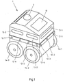
- FIG. 1 Figure 3 is a schematic representation of an exemplary embodiment of an unmanned vehicle 1 according to the invention.
- the unmanned vehicle 1 is a land vehicle and has a receiving compartment 10 closed by a door.
- the unmanned vehicle 1 can transport a shipment in the receiving compartment 10.
- the unmanned vehicle 1 is one Outdoor robots or a transport drone.
- the unmanned vehicle is set up to move at least partially autonomously.
- the unmanned vehicle 1 has a device 2 which is set up, for example, to implement a method according to the invention (for example the method according to the flowchart in FIG Fig. 4 ) to execute.
- a device 2 which is set up, for example, to implement a method according to the invention (for example the method according to the flowchart in FIG Fig. 4 ) to execute.
- the unmanned vehicle 1 has, for example, a plurality of environmental sensors 12-1 to 12-7, which are arranged on different outside of the unmanned vehicle 1.
- the environment sensors 12-1 to 12-7 are set up, for example, to at least partially monitor the environment of the unmanned vehicle 1 and to acquire sensor information that represents at least one object parameter of an object that is located in the vicinity of the unmanned vehicle.
- the unmanned vehicle 1, in addition to the environmental sensors 12-1 to 12-7 has additional sensors (for example environmental sensors that are attached to in Fig. 1 non-visible outsides of the unmanned vehicle 1 can be arranged, and / or vehicle sensors).
- the device 2 can also comprise one or more further sensors (for example environmental sensors and / or vehicle sensors), which would thus be part of both the device 2 and the unmanned vehicle 1.
- the environmental sensors 12-1 to 12-7 are ultrasonic sensors which are set up to record ultrasonic sensor information (for example in the form of an ultrasonic signal transit time).
- the ultrasonic sensors 12-1 to 12-7 are each set up to emit an ultrasonic pulse and receive a reflection of the ultrasonic pulse and to measure an ultrasonic signal transit time (ie the period between the transmission of the ultrasonic pulse and the reception of the reflection of the ultrasonic pulse). Based on such an ultrasonic signal transit time, the distance between the unmanned vehicle 1 and the object on which the ultrasonic pulse was reflected can be determined.
- the unmanned vehicle 1 can additionally or alternatively also comprise other sensors (temperature sensors, electromagnetic sensors, acoustic sensors and / or optical sensors) as environmental sensors 12-1 to 12-7.
- the unmanned vehicle 1 includes a plurality of crash pads 13-1, 13-2 and 13-3 (ie, a plurality of crash pads 13-1 to 13-3) arranged on different outer sides of the unmanned vehicle 1. It goes without saying that the unmanned vehicle 1 can comprise further impact cushions (for example impact cushions which are attached to in Fig. 1 non-visible outsides of the unmanned vehicle 1 can be arranged).
- each of the airbag devices 13-1 to 13-3 comprises, for example, a respective airbag and a respective gas generator, the airbag device being set up, when it is triggered, to fill the airbag with gas generated by the gas generator, so that the The gas bag opens or unfolds.
- the gas bag is, for example, a plastic bag (e.g. a nylon bag).
- the gas generator is, for example, a pyrotechnic gas generator, a cold gas generator or a hybrid gas generator.
- the respective gas generator of each of the airbag devices 13-1 to 13-3 comprises two propellant charges.
- each of the airbag devices 13-1 to 13-3 can be triggered with two different triggering intensities.
- the lower triggering intensity corresponds, for example, to the case that only one propellant charge of the respective airbag device is ignited, and the higher triggering intensity corresponds, for example, to the case that both propellant charges of the respective airbag device are ignited.
- the ultrasonic sensors 12-1 to 12-7 and the airbag devices 13-1 to 13-3 of the unmanned vehicle with the device 2 via one or more wired communication connections e.g. via one or more bus systems such as one or more serial and / or parallel bus connections of the unmanned vehicle 1 communicatively connected.
- the ultrasonic sensors 12-1 to 12-7 and the airbag devices 13-1 to 13-3 have one or more corresponding wired communication interfaces.
- ultrasonic sensors 12-1 to 12-7 and the airbag devices 13-1 to 13-3 can also have a wireless communication link to be communicatively connected to the device 2.
- the ultrasonic sensors 12-1 to 12-7 and the airbag devices 13-1 to 13-3 can comprise one or more wireless communication interfaces.
- a wired communication connection should preferably be understood to mean a communication connection via a wired communication network such as an Ethernet communication network, a CAN bus system (Controller Area Network), a K-line bus system or a FlexRay bus system.
- Ethernet is specified, for example, in the standards of the IEEE 802.3 family.
- CAN is specified in the standards of the ISO 11898 family
- K line is specified in the standards ISO 9141 and ISO 14230-1
- FlexRay in the standards of the ISO 17458 family.
- An example of a wireless communication link is a communication link based on wireless communication technology such as radio frequency identification (RFID) and / or near field communication (NFC) and / or Bluetooth (eg Bluetooth version 2.1 and / or 4.0) and / or wireless local area network (WIRELESS INTERNET ACCESS).
- RFID and NFC are specified, for example, according to ISO standards 18000, 11784/11785 and ISO / IEC standards 14443-A and 15693.
- the Bluetooth specifications are currently available on the Internet at www.bluetooth.org.
- WLAN is specified, for example, in the standards of the IEEE 802.11 family.
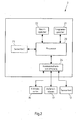
- FIG. 3 is a schematic representation of an exemplary embodiment of a device 2 (e.g. that of FIG Fig. 1 illustrated device 2) according to the invention.
- the device 2 comprises, for example, a processor 20 and, connected to the processor 20, a first memory as program memory 21, a second memory as main memory 22 and a wired communication interface 24. Furthermore, the device 2 can optionally include one or more sensors 23 (e.g. an environmental sensor) .
- sensors 23 e.g. an environmental sensor
- a processor such as processor 20 should be understood to mean, for example, a microprocessor, a microcontroller, a microcontroller, a digital signal processor (DSP), an application-specific integrated circuit (ASIC) or a field programmable gate array (FPGA). It goes without saying that the device 2 can also comprise a plurality of processors 20.
- DSP digital signal processor
- ASIC application-specific integrated circuit
- FPGA field programmable gate array
- Processor 20 executes program instructions that are stored in program memory 21 and stores, for example, intermediate results or the like in main memory 22.
- Program memory 21 contains, for example, program instructions of a computer program that includes program instructions that cause processor 20 to use the disclosed method (e.g. the method according to the in Fig. 4 flowchart 400 shown) and / or to control when the processor 20 executes these program instructions stored in program memory 21.
- the program memory 21 also contains, for example, the operating system of the device 2, which is at least partially loaded into the main memory 22 when the device 2 is started and executed by the processor 20.
- the operating system of the device 2 which is at least partially loaded into the main memory 22 when the device 2 is started and executed by the processor 20.
- the device 2 when the device 2 is started, at least part of the core of the operating system is loaded into the main memory 22 and executed by the processor 20.
- an operating system is a Windows, UNIX, Linux, Android, Apple iOS and / or MAC OS operating system.
- the operating system enables the device 2 to be used for data processing. For example, it manages resources such as a main memory and a program memory, provides other computer programs with basic functions through programming interfaces and controls the execution of computer programs.
- a program memory such as program memory 21 is, for example, a non-volatile memory such as a flash memory, a magnetic memory, an EEPROM memory (electrically erasable programmable read-only memory) and / or an optical memory.
- a main memory such as main memory 22 is, for example, a volatile or non-volatile memory, in particular a memory with random access (RAM) such as a static RAM memory (SRAM), a dynamic RAM memory (DRAM), a ferroelectric RAM memory (FeRAM) and / or a magnetic RAM memory (MRAM).
- RAM random access
- SRAM static RAM memory
- DRAM dynamic RAM memory
- FeRAM ferroelectric RAM memory
- MRAM magnetic RAM memory
- Main memory 22 and program memory 21 can also be designed as one memory.
- main memory 22 and / or program memory 21 can each be formed by a plurality of memories.
- main memory 22 and / or program memory 21 can also be part of processor 20.
- the communication interface 24 of the device 2 can be a wireless or a wired communication interface, a wired communication interface being assumed in the following as an example.
- the device 2 can send and / or receive information by means of the communication interface 24.
- the device 2 can receive sensor information from the environmental sensors 12-1 to 12-7 of the unmanned vehicle 1 by means of the communication interface 24.
- the device 2 can use the communication interface 24 to trigger one or more of the airbag devices 13-1 to 13-3 of the unmanned vehicle 1 by sending control information to the respective airbag device in order to control the respective airbag device and triggering the respective airbag device Control airbag device.
- the triggering of the respective airbag device can be controlled in such a way that it takes place according to one or more (previously determined) triggering parameters.
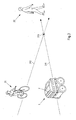
- Fig. 3 is a schematic representation of a situation in which a method according to the invention can run, the situation for example according to Fig. 1 disclosed unmanned vehicle 1, which the after Fig. 2 disclosed device 2 comprises.
- the unmanned vehicle 1 moves automatically and follows a person 32 (e.g. a parcel deliverer) (e.g. in a follow-me mode).
- a cyclist 31 e.g., a bicycle and a rider of the bicycle is located in the vicinity of the unmanned vehicle 1, and the cyclist 31 moves with respect to the unmanned vehicle 1.
- FIG. 4 shows a flow chart 400 of an exemplary embodiment of a method according to the invention, the method steps 401 to 405 of which with a view to the FIGS Fig. 3 depicted situation are explained below by way of example. It is assumed here by way of example that the following method steps 401 to 405 are carried out by the device 2 of the unmanned vehicle 1.
- the device 2 receives sensor information, the sensor information being detected by at least one environment sensor of the environment sensors 12-1 to 12-7 of the unmanned vehicle 1 and at least one object parameter of the cyclist 31 as an object that is related to the unmanned vehicle Vehicle 1 moves, represents.
- the sensor information represents the distance of the cyclist 31 to the unmanned vehicle 1 as an object parameter of the cyclist 31.
- a plurality of sensor information recorded by at least one environmental sensor of the environmental sensors 12-1 to 12-7 of the unmanned vehicle 1 can be obtained.
- such multiple pieces of sensor information could represent the distance of the cyclist 31 from the unmanned vehicle 1 at successive points in time as object parameters of the cyclist 31.
- an average differential speed of the cyclist 31 at which the cyclist 31 approaches the unmanned vehicle or moves away from it can be determined based on such a time profile of the distance.
- the device 2 determines, based at least in part on the at least one object parameter that is represented by the sensor information obtained in step 401, whether a collision between the unmanned vehicle 1 and the cyclist 31 is imminent.
- the determination in step 402 takes place, for example, according to one or more (eg predetermined) rules such as an algorithm or a decision model.
- the determination in step 402 takes place at least partially based on a decision model obtained by machine learning, such as an artificial neural network or an AI-based decision matrix.
- the decision model receives the at least one object parameter, which is represented by the sensor information obtained in step 401, as an input parameter and outputs, for example, a probability of a collision between the unmanned vehicle 1 and the cyclist 31 as an output parameter.
- the decision model has additional object parameters and / or vehicle parameters than Receive input parameters and can thus take into account when determining the probability of a collision occurring between the unmanned vehicle 1 and the cyclist 31.
- a predetermined threshold value e.g. 50%, 75% or 90%
- step 402 it is determined in step 402 that there is no threat of a collision between the unmanned vehicle 1 and the cyclist 31. In this case, the method is ended in step 403, for example.
- step 402 If, on the other hand, it is determined in step 402 that a collision is imminent between the unmanned vehicle 1 and the cyclist 31, the method continues with step 404.
- step 404 the device 2 determines, based at least partially on the at least one object parameter represented by the sensor information obtained in step 401, at least one triggering parameter for triggering at least one airbag device of the airbag devices 13-1 to 13-3 of the unmanned vehicle 1
- a plurality of trigger parameters can also be determined in step 404.
- the triggering parameters determined in step 404 define, for example, the airbag device (s) of the airbag devices 13-1 to 13-3 that is to be triggered and / or the respective triggering time and / or the respective triggering intensity.
- the cyclist 31 threatens to collide with the front outside of the unmanned vehicle 1 as seen in the direction of travel, so that the triggering parameter is determined, for example, such that it stipulates that the airbag device 13-1 arranged on this outside of the unmanned vehicle 1 is triggered should.
- a further triggering parameter is determined in step 404, for example, in such a way that it defines the triggering time in such a way that the airbag device 13-1 is triggered before the impending collision.
- a further triggering parameter is determined in step 404, which determines the triggering intensity.
- the triggering parameter is determined in such a way that it specifies that the airbag device 13-1 should be triggered with the higher triggering intensity when the cyclist 31 approaches the unmanned vehicle 1 with an average differential speed greater than or equal to a the predetermined threshold value (e.g. 5 m / s) approaches. Otherwise it can be provided, for example, that the triggering parameter is determined in such a way that it stipulates that the airbag device 13-1 should be triggered with the lower triggering intensity.
- step 405 the at least one airbag device of the airbag devices 13-1 to 13-3 is triggered and / or triggered according to the at least one trigger parameter determined in step 404, the at least one airbag device being triggered before the impending collision.
- the device 2 triggers the airbag device 13-1 in step 405 according to the trigger parameters determined in step 404, the airbag device 13-1 being triggered before the impending collision between the unmanned vehicle 1 and the cyclist 31, for example by the device 2 controls the airbag device in such a way that the propellant charge (s) of the airbag device 13-1 are ignited in accordance with the trigger parameters determined in step 404.
- the triggering of the airbag device 13-1 in step 405 before the impending collision according to the triggering parameters determined in step 404 is particularly advantageous, since damage as a result of an impending collision, for the unmanned vehicle 1, for example due to its small size compared to the rest Road users are at an increased risk, can be prevented or reduced particularly effectively.
- the triggering of an airbag device 13-1 in step 405 can be particularly advantageous because the airbag device 13-1 according to the at least one specific trigger parameter occurs before the impending collision between the unmanned vehicle 1 and the cyclist 31 (e.g. before the physical contact between the unmanned Vehicle 1 and the cyclist 31 if the impending collision actually occurs) is triggered.
- the triggering of an airbag device as a crash cushion in step 405 before the impending collision can be particularly advantageous because a lower trigger intensity (e.g. a lower speed at which the crash cushion opens) can already be sufficient compared to conventional triggering methods to protect against collision damage.
- a lower trigger intensity e.g. a lower speed at which the crash cushion opens
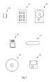
- FIG. 4 shows exemplary embodiments of storage media on which an exemplary embodiment of a computer program according to the invention can be stored.
- the storage medium can be, for example, a magnetic, electrical, optical and / or other type of storage medium.
- the storage medium can, for example, be part of a processor (eg the processor 20 of the Fig. 2 ), for example a (non-volatile or volatile) program memory of the processor or a part thereof (e.g. memory 21 in Fig. 2 ).
- Embodiments of a storage medium are a flash memory 50, an SSD hard disk 51, a magnetic hard disk 52, a memory card 53, a memory stick 54 (e.g. a USB stick), a CD-ROM or DVD 55 or a floppy disk 56.
- a flash memory 50 an SSD hard disk 51, a magnetic hard disk 52, a memory card 53, a memory stick 54 (e.g. a USB stick), a CD-ROM or DVD 55 or a floppy disk 56.
Landscapes
- Engineering & Computer Science (AREA)
- Mechanical Engineering (AREA)
- Radar, Positioning & Navigation (AREA)
- Remote Sensing (AREA)
- Physics & Mathematics (AREA)
- General Physics & Mathematics (AREA)
- Control Of Position, Course, Altitude, Or Attitude Of Moving Bodies (AREA)
- Traffic Control Systems (AREA)
Applications Claiming Priority (1)
| Application Number | Priority Date | Filing Date | Title |
|---|---|---|---|
| DE102019119093.2A DE102019119093B4 (de) | 2019-07-15 | 2019-07-15 | Auslösen zumindest eines Aufprallkissens eines unbemannten Fahrzeugs |
Publications (3)
| Publication Number | Publication Date |
|---|---|
| EP3766744A1 true EP3766744A1 (fr) | 2021-01-20 |
| EP3766744C0 EP3766744C0 (fr) | 2025-04-02 |
| EP3766744B1 EP3766744B1 (fr) | 2025-04-02 |
Family
ID=71515039
Family Applications (1)
| Application Number | Title | Priority Date | Filing Date |
|---|---|---|---|
| EP20184164.0A Active EP3766744B1 (fr) | 2019-07-15 | 2020-07-06 | Déclenchement d'au moins un coussin gonflable d'un véhicule sans équipage |
Country Status (4)
| Country | Link |
|---|---|
| US (1) | US11472362B2 (fr) |
| EP (1) | EP3766744B1 (fr) |
| CN (1) | CN112224165A (fr) |
| DE (1) | DE102019119093B4 (fr) |
Families Citing this family (10)
| Publication number | Priority date | Publication date | Assignee | Title |
|---|---|---|---|---|
| JP7340402B2 (ja) * | 2019-10-01 | 2023-09-07 | 株式会社ダイセル | 乗員保護システム |
| JP7380171B2 (ja) * | 2019-12-17 | 2023-11-15 | 株式会社デンソー | 運転支援装置および運転支援プログラム |
| US20220063679A1 (en) * | 2020-08-26 | 2022-03-03 | Karma Automotive Llc | Logistics system |
| DE102021207126A1 (de) | 2021-07-07 | 2023-01-12 | Zf Friedrichshafen Ag | Verfahren zum Betreiben eines Sicherheitssystems eines Fahrzeugs, Computerprogrammprodukt, Vorrichtung und Steuergerät |
| US20230252903A1 (en) * | 2022-02-08 | 2023-08-10 | Nullmax (Hong Kong) Limited | Autonomous driving system with air support |
| US12330821B2 (en) | 2022-02-08 | 2025-06-17 | Nullmax (Hong Kong) Limited | Autonomous driving system with air support |
| CN114675640B (zh) * | 2022-03-03 | 2025-07-22 | 北京三快在线科技有限公司 | 一种无人设备、保护方法、装置、电子设备及存储介质 |
| DE102023112088B3 (de) | 2023-05-09 | 2024-10-17 | Cariad Se | Verfahren zum Vorbereiten eines Kraftfahrzeugs auf eine Kollision |
| DE102023116663A1 (de) * | 2023-06-23 | 2024-12-24 | Otto-von-Guericke-Universität Magdeburg, Körperschaft des öffentlichen Rechts | Verfahren zum Betreiben eines Transportfahrzeugs, Steuerungsvorrichtung, Speichermedium und Transportfahrzeug |
| DE102023002858A1 (de) * | 2023-07-14 | 2025-01-16 | Mercedes-Benz Group AG | Verfahren und Vorrichtung zur Kollisionserkennung eines Fahrzeugs |
Citations (4)
| Publication number | Priority date | Publication date | Assignee | Title |
|---|---|---|---|---|
| DE10327115B3 (de) * | 2003-06-13 | 2004-11-11 | Rehau Ag + Co. | Fußgängerschutzsystem für Kraftfahrzeuge |
| WO2010040376A1 (fr) * | 2008-10-06 | 2010-04-15 | Alexander Augst | Procédé de réduction des risques de collision |
| JP2017124809A (ja) * | 2016-01-07 | 2017-07-20 | シャープ株式会社 | 自律走行車両 |
| EP3312810A1 (fr) * | 2016-10-20 | 2018-04-25 | Deutsche Post AG | Dispositif de prévention d'un danger |
Family Cites Families (26)
| Publication number | Priority date | Publication date | Assignee | Title |
|---|---|---|---|---|
| DE8232628U1 (de) | 1983-04-07 | Wollert, Wolfgang, Dipl.-Ing. | Auffahrschutzvorrichtung für Fahrzeuge | |
| US5732785A (en) * | 1996-03-28 | 1998-03-31 | Transmart Technologies, Inc. | Proactive exterior airbag system and its deployment method for a motor vehicle |
| DE10132681C1 (de) | 2001-07-05 | 2002-08-22 | Bosch Gmbh Robert | Verfahren zur Klassifizierung von einem Hindernis anhand von Precrashsensorsignalen |
| US6950014B2 (en) * | 2002-02-13 | 2005-09-27 | Ford Global Technologies Llc | Method for operating a pre-crash sensing system in a vehicle having external airbags |
| IL150123A0 (en) * | 2002-06-10 | 2003-07-06 | Shahar Avneri | Security system |
| DE10326001B4 (de) | 2003-02-26 | 2014-02-13 | Volkswagen Ag | Verfahren und Einrichtung zur Ansteuerung einer Sicherheitseinrichtung bei einem Kraftfahrzeug |
| US20060106538A1 (en) * | 2004-11-12 | 2006-05-18 | Browne Alan L | Cooperative collision mitigation |
| DE102006008636A1 (de) | 2006-02-24 | 2007-08-30 | Robert Bosch Gmbh | Sensorik und zugehöriges Verfahren zur Objekterkennung für ein Fahrzeug |
| DE102010003333B4 (de) * | 2010-03-26 | 2020-07-30 | Robert Bosch Gmbh | Verfahren und Vorrichtung zur Bestimmung von zumindest einem Auslöseparameter eines Personenschutzmittels eines Fahrzeugs |
| KR20120063626A (ko) * | 2010-12-08 | 2012-06-18 | 현대자동차주식회사 | 외장에어백의 제어장치 및 제어방법 |
| KR101428260B1 (ko) * | 2012-12-10 | 2014-08-07 | 현대자동차주식회사 | 외장에어백 전개방법 |
| EP2845779B1 (fr) * | 2013-09-09 | 2018-08-01 | Honda Research Institute Europe GmbH | Technique d'assistance à la conduite pour commande active de véhicule |
| DE102014002540B4 (de) | 2014-02-22 | 2018-08-30 | Audi Ag | Sicherheitseinrichtung für ein Kraftfahrzeug und zugehöriges Betriebsverfahren |
| KR101583928B1 (ko) * | 2014-05-12 | 2016-01-11 | 현대자동차주식회사 | 외장에어백 전개방법 |
| US9804599B2 (en) * | 2015-11-04 | 2017-10-31 | Zoox, Inc. | Active lighting control for communicating a state of an autonomous vehicle to entities in a surrounding environment |
| US10580301B2 (en) * | 2016-03-16 | 2020-03-03 | Kiomars Anvari | Moving vehicles in a smart environment |
| WO2017177205A1 (fr) * | 2016-04-08 | 2017-10-12 | Faraday & Future Inc. | Capteur mobile destiné à une conduite autonome |
| US10183641B2 (en) * | 2017-03-23 | 2019-01-22 | Baidu Usa Llc | Collision prediction and forward airbag deployment system for autonomous driving vehicles |
| CN108146378A (zh) * | 2018-01-12 | 2018-06-12 | 吴盼婷 | 一种电动汽车的安全气囊控制系统及电动汽车 |
| CN108583495B (zh) * | 2018-04-26 | 2021-09-24 | 刘宗烨 | 一种汽车被动安全系统 |
| DE102018111153A1 (de) | 2018-05-09 | 2019-11-14 | Deutsche Post Ag | Transportwagen für Sendungen und Verfahren zum Betrieb des Transportwagens |
| JP7111517B2 (ja) * | 2018-06-14 | 2022-08-02 | シャープ株式会社 | 走行装置、走行装置の走行制御方法、走行装置の走行制御プログラムおよび記録媒体 |
| US20200020234A1 (en) * | 2018-07-10 | 2020-01-16 | Cavh Llc | Safety technologies for connected automated vehicle highway systems |
| US10858011B1 (en) * | 2018-07-13 | 2020-12-08 | State Farm Mutual Automobile Insurance Company | Dynamic safe storage of vehicle content |
| US10953830B1 (en) * | 2018-07-13 | 2021-03-23 | State Farm Mutual Automobile Insurance Company | Adjusting interior configuration of a vehicle based on vehicle contents |
| US11427146B2 (en) * | 2019-07-10 | 2022-08-30 | Pony Ai Inc. | Collision protection |
-
2019
- 2019-07-15 DE DE102019119093.2A patent/DE102019119093B4/de active Active
-
2020
- 2020-07-06 EP EP20184164.0A patent/EP3766744B1/fr active Active
- 2020-07-15 CN CN202010679850.4A patent/CN112224165A/zh active Pending
- 2020-07-15 US US16/929,888 patent/US11472362B2/en active Active
Patent Citations (4)
| Publication number | Priority date | Publication date | Assignee | Title |
|---|---|---|---|---|
| DE10327115B3 (de) * | 2003-06-13 | 2004-11-11 | Rehau Ag + Co. | Fußgängerschutzsystem für Kraftfahrzeuge |
| WO2010040376A1 (fr) * | 2008-10-06 | 2010-04-15 | Alexander Augst | Procédé de réduction des risques de collision |
| JP2017124809A (ja) * | 2016-01-07 | 2017-07-20 | シャープ株式会社 | 自律走行車両 |
| EP3312810A1 (fr) * | 2016-10-20 | 2018-04-25 | Deutsche Post AG | Dispositif de prévention d'un danger |
Also Published As
| Publication number | Publication date |
|---|---|
| DE102019119093A1 (de) | 2021-01-21 |
| CN112224165A (zh) | 2021-01-15 |
| US11472362B2 (en) | 2022-10-18 |
| EP3766744C0 (fr) | 2025-04-02 |
| DE102019119093B4 (de) | 2023-05-04 |
| EP3766744B1 (fr) | 2025-04-02 |
| US20210016735A1 (en) | 2021-01-21 |
Similar Documents
| Publication | Publication Date | Title |
|---|---|---|
| EP3766744B1 (fr) | Déclenchement d'au moins un coussin gonflable d'un véhicule sans équipage | |
| DE102006041725B4 (de) | Verfahren und Vorrichtung zum Betrieb einer Vor-Aufprall-Erfassungsanordnung mit Kontaktsensor | |
| EP3083361B1 (fr) | Procédé et dispositif pour surveiller une cote extérieure d'un véhicule | |
| DE102017113596A1 (de) | Erkennen von gefahren in erwartung sich öffnender fahrzeugtüren | |
| DE102017116582A1 (de) | Fahrzeugferneinparkhilfe mit insassenerfassung | |
| EP2753532A1 (fr) | Procédé et dispositif pour un système d'assistance d'un véhicule servant à exécuter une man uvre autonome ou partiellement autonome | |
| DE102016226040A1 (de) | Verfahren und Vorrichtung in einem Kraftfahrzeug zum Fußgängerschutz | |
| DE112017007735T5 (de) | System und -verfahren zur fahrzeugüberprüfung | |
| WO2020020504A1 (fr) | Système de protection de passagers, véhicule automobile et procédé servant à faire fonctionner un système de protection de passagers | |
| DE102022121324A1 (de) | Verbessertes insassenkollisionssicherheitssystem | |
| DE102020122086A1 (de) | Messen von vertrauen in tiefen neuronalen netzwerken | |
| DE102015001861A1 (de) | Verfahren zur Umgebungsüberwachung | |
| DE102019216805A1 (de) | Verfahren zum Verfolgen eines entfernten Zielfahrzeugs in einem Umgebungsbereich eines Kraftfahrzeugs mittels einer Kollisionserkennungsvorrichtung | |
| WO2019081206A1 (fr) | Dispositif et procédé de régulation adaptative de véhicule | |
| DE112015004722T5 (de) | Auffahrunfallschutz | |
| DE10335601B4 (de) | Verfahren zur Objektklassifizierung unter Verwendung einer 3D-Modelldatenbank | |
| DE102023113852A1 (de) | Objekterkennung um fahrzeugladestationen | |
| DE102014215430A1 (de) | Verfahren und Vorrichtung zum Überwachen eines abgestellten Fahrzeugs | |
| DE102016207376A1 (de) | Verfahren und Vorrichtung zum Erkennen von zumindest einer Position einer Person und/oder einer veränderten Position der Person oder einer weiteren Person für ein Fahrzeug und Verfahren zum Aktivieren eines Personenschutzmittels für ein Fahrzeug | |
| DE102018222518A1 (de) | Kamerasystem mit hoher Updaterate | |
| WO2025012194A1 (fr) | Procédé pour faire fonctionner un système d'assistance d'un véhicule automobile fonctionnant de manière au moins partiellement assistée, produit programme d'ordinateur, support d'enregistrement lisible par ordinateur et système d'assistance | |
| DE102022123154A1 (de) | Systeme und verfahren zum verfolgen von ausrüstungsschutzkabel | |
| DE102019113927B4 (de) | SYSTEM UND VERFAHREN ZUM ANZEIGEN VON INFORMATIONEN NACH EINEM FUßGÄNGERUNFALL | |
| DE102016216979A1 (de) | Verfahren und Steuergerät zum Personenschutz für ein Fahrzeug | |
| DE102022206131A1 (de) | Klassifikator und Verfahren für die Erkennung von Objekten aus Sensordaten auf der Basis einer vorgegebenen Klassenhierarchie |
Legal Events
| Date | Code | Title | Description |
|---|---|---|---|
| PUAI | Public reference made under article 153(3) epc to a published international application that has entered the european phase |
Free format text: ORIGINAL CODE: 0009012 |
|
| STAA | Information on the status of an ep patent application or granted ep patent |
Free format text: STATUS: THE APPLICATION HAS BEEN PUBLISHED |
|
| AK | Designated contracting states |
Kind code of ref document: A1 Designated state(s): AL AT BE BG CH CY CZ DE DK EE ES FI FR GB GR HR HU IE IS IT LI LT LU LV MC MK MT NL NO PL PT RO RS SE SI SK SM TR |
|
| AX | Request for extension of the european patent |
Extension state: BA ME |
|
| RIN1 | Information on inventor provided before grant (corrected) |
Inventor name: BISCHOFF, HEIKE Inventor name: TRENDAFILOV, BORIS Inventor name: DREES, SANDRA Inventor name: KONG, DONG UCK Inventor name: RADETZKI, UWE |
|
| STAA | Information on the status of an ep patent application or granted ep patent |
Free format text: STATUS: REQUEST FOR EXAMINATION WAS MADE |
|
| 17P | Request for examination filed |
Effective date: 20210719 |
|
| RBV | Designated contracting states (corrected) |
Designated state(s): AL AT BE BG CH CY CZ DE DK EE ES FI FR GB GR HR HU IE IS IT LI LT LU LV MC MK MT NL NO PL PT RO RS SE SI SK SM TR |
|
| RIN1 | Information on inventor provided before grant (corrected) |
Inventor name: DREES, SANDRA Inventor name: BISCHOFF, HEIKE Inventor name: TRENDAFILOV, BORIS Inventor name: KONG, DONG UCK Inventor name: RADETZKI, UWE |
|
| STAA | Information on the status of an ep patent application or granted ep patent |
Free format text: STATUS: EXAMINATION IS IN PROGRESS |
|
| 17Q | First examination report despatched |
Effective date: 20230922 |
|
| GRAP | Despatch of communication of intention to grant a patent |
Free format text: ORIGINAL CODE: EPIDOSNIGR1 |
|
| STAA | Information on the status of an ep patent application or granted ep patent |
Free format text: STATUS: GRANT OF PATENT IS INTENDED |
|
| RIC1 | Information provided on ipc code assigned before grant |
Ipc: B60R 21/01 20060101ALN20241101BHEP Ipc: G08G 1/04 20060101ALI20241101BHEP Ipc: G08G 1/16 20060101ALI20241101BHEP Ipc: G08G 1/00 20060101ALI20241101BHEP Ipc: B60R 21/0134 20060101AFI20241101BHEP |
|
| INTG | Intention to grant announced |
Effective date: 20241122 |
|
| GRAS | Grant fee paid |
Free format text: ORIGINAL CODE: EPIDOSNIGR3 |
|
| GRAA | (expected) grant |
Free format text: ORIGINAL CODE: 0009210 |
|
| STAA | Information on the status of an ep patent application or granted ep patent |
Free format text: STATUS: THE PATENT HAS BEEN GRANTED |
|
| AK | Designated contracting states |
Kind code of ref document: B1 Designated state(s): AL AT BE BG CH CY CZ DE DK EE ES FI FR GB GR HR HU IE IS IT LI LT LU LV MC MK MT NL NO PL PT RO RS SE SI SK SM TR |
|
| REG | Reference to a national code |
Ref country code: GB Ref legal event code: FG4D Free format text: NOT ENGLISH |
|
| REG | Reference to a national code |
Ref country code: CH Ref legal event code: EP |
|
| REG | Reference to a national code |
Ref country code: IE Ref legal event code: FG4D Free format text: LANGUAGE OF EP DOCUMENT: GERMAN |
|
| REG | Reference to a national code |
Ref country code: DE Ref legal event code: R096 Ref document number: 502020010723 Country of ref document: DE |
|
| U01 | Request for unitary effect filed |
Effective date: 20250410 |
|
| U07 | Unitary effect registered |
Designated state(s): AT BE BG DE DK EE FI FR IT LT LU LV MT NL PT RO SE SI Effective date: 20250416 |
|
| U20 | Renewal fee for the european patent with unitary effect paid |
Year of fee payment: 6 Effective date: 20250722 |
|
| PG25 | Lapsed in a contracting state [announced via postgrant information from national office to epo] |
Ref country code: ES Free format text: LAPSE BECAUSE OF FAILURE TO SUBMIT A TRANSLATION OF THE DESCRIPTION OR TO PAY THE FEE WITHIN THE PRESCRIBED TIME-LIMIT Effective date: 20250402 |
|
| PG25 | Lapsed in a contracting state [announced via postgrant information from national office to epo] |
Ref country code: NO Free format text: LAPSE BECAUSE OF FAILURE TO SUBMIT A TRANSLATION OF THE DESCRIPTION OR TO PAY THE FEE WITHIN THE PRESCRIBED TIME-LIMIT Effective date: 20250702 Ref country code: GR Free format text: LAPSE BECAUSE OF FAILURE TO SUBMIT A TRANSLATION OF THE DESCRIPTION OR TO PAY THE FEE WITHIN THE PRESCRIBED TIME-LIMIT Effective date: 20250703 |
|
| PG25 | Lapsed in a contracting state [announced via postgrant information from national office to epo] |
Ref country code: PL Free format text: LAPSE BECAUSE OF FAILURE TO SUBMIT A TRANSLATION OF THE DESCRIPTION OR TO PAY THE FEE WITHIN THE PRESCRIBED TIME-LIMIT Effective date: 20250402 |
|
| PGFP | Annual fee paid to national office [announced via postgrant information from national office to epo] |
Ref country code: GB Payment date: 20250722 Year of fee payment: 6 |
|
| PG25 | Lapsed in a contracting state [announced via postgrant information from national office to epo] |
Ref country code: HR Free format text: LAPSE BECAUSE OF FAILURE TO SUBMIT A TRANSLATION OF THE DESCRIPTION OR TO PAY THE FEE WITHIN THE PRESCRIBED TIME-LIMIT Effective date: 20250402 |
|
| PG25 | Lapsed in a contracting state [announced via postgrant information from national office to epo] |
Ref country code: RS Free format text: LAPSE BECAUSE OF FAILURE TO SUBMIT A TRANSLATION OF THE DESCRIPTION OR TO PAY THE FEE WITHIN THE PRESCRIBED TIME-LIMIT Effective date: 20250702 |
|
| PG25 | Lapsed in a contracting state [announced via postgrant information from national office to epo] |
Ref country code: IS Free format text: LAPSE BECAUSE OF FAILURE TO SUBMIT A TRANSLATION OF THE DESCRIPTION OR TO PAY THE FEE WITHIN THE PRESCRIBED TIME-LIMIT Effective date: 20250802 |
|
| PG25 | Lapsed in a contracting state [announced via postgrant information from national office to epo] |
Ref country code: SM Free format text: LAPSE BECAUSE OF FAILURE TO SUBMIT A TRANSLATION OF THE DESCRIPTION OR TO PAY THE FEE WITHIN THE PRESCRIBED TIME-LIMIT Effective date: 20250402 |
|
| PG25 | Lapsed in a contracting state [announced via postgrant information from national office to epo] |
Ref country code: CZ Free format text: LAPSE BECAUSE OF FAILURE TO SUBMIT A TRANSLATION OF THE DESCRIPTION OR TO PAY THE FEE WITHIN THE PRESCRIBED TIME-LIMIT Effective date: 20250402 |
|
| PG25 | Lapsed in a contracting state [announced via postgrant information from national office to epo] |
Ref country code: SK Free format text: LAPSE BECAUSE OF FAILURE TO SUBMIT A TRANSLATION OF THE DESCRIPTION OR TO PAY THE FEE WITHIN THE PRESCRIBED TIME-LIMIT Effective date: 20250402 |
|
| PLBE | No opposition filed within time limit |
Free format text: ORIGINAL CODE: 0009261 |
|
| STAA | Information on the status of an ep patent application or granted ep patent |
Free format text: STATUS: NO OPPOSITION FILED WITHIN TIME LIMIT |
|
| REG | Reference to a national code |
Ref country code: CH Ref legal event code: L10 Free format text: ST27 STATUS EVENT CODE: U-0-0-L10-L00 (AS PROVIDED BY THE NATIONAL OFFICE) Effective date: 20260211 |
|
| REG | Reference to a national code |
Ref country code: CH Ref legal event code: H13 Free format text: ST27 STATUS EVENT CODE: U-0-0-H10-H13 (AS PROVIDED BY THE NATIONAL OFFICE) Effective date: 20260224 |
|
| 26N | No opposition filed |
Effective date: 20260105 |
|
| PG25 | Lapsed in a contracting state [announced via postgrant information from national office to epo] |
Ref country code: CH Free format text: LAPSE BECAUSE OF NON-PAYMENT OF DUE FEES Effective date: 20250731 |