EP3767061A1 - Entraînement pour une porte, en particulier un meuble ou un appareil, procédé de fonctionnement d'un tel entraînement de porte ainsi que dispositif doté d'au moins un tel entraînement de porte - Google Patents
Entraînement pour une porte, en particulier un meuble ou un appareil, procédé de fonctionnement d'un tel entraînement de porte ainsi que dispositif doté d'au moins un tel entraînement de porte Download PDFInfo
- Publication number
- EP3767061A1 EP3767061A1 EP19425052.8A EP19425052A EP3767061A1 EP 3767061 A1 EP3767061 A1 EP 3767061A1 EP 19425052 A EP19425052 A EP 19425052A EP 3767061 A1 EP3767061 A1 EP 3767061A1
- Authority
- EP
- European Patent Office
- Prior art keywords
- coupling
- door
- rotation
- relative
- actuating
- Prior art date
- Legal status (The legal status is an assumption and is not a legal conclusion. Google has not performed a legal analysis and makes no representation as to the accuracy of the status listed.)
- Granted
Links
Images


Classifications
-
- E—FIXED CONSTRUCTIONS
- E05—LOCKS; KEYS; WINDOW OR DOOR FITTINGS; SAFES
- E05F—DEVICES FOR MOVING WINGS INTO OPEN OR CLOSED POSITION; CHECKS FOR WINGS; WING FITTINGS NOT OTHERWISE PROVIDED FOR, CONCERNED WITH THE FUNCTIONING OF THE WING
- E05F15/00—Power-operated mechanisms for wings
- E05F15/60—Power-operated mechanisms for wings using electrical actuators
- E05F15/603—Power-operated mechanisms for wings using electrical actuators using rotary electromotors
- E05F15/611—Power-operated mechanisms for wings using electrical actuators using rotary electromotors for swinging wings
- E05F15/616—Power-operated mechanisms for wings using electrical actuators using rotary electromotors for swinging wings operated by push-pull mechanisms
- E05F15/622—Power-operated mechanisms for wings using electrical actuators using rotary electromotors for swinging wings operated by push-pull mechanisms using screw-and-nut mechanisms
-
- F—MECHANICAL ENGINEERING; LIGHTING; HEATING; WEAPONS; BLASTING
- F16—ENGINEERING ELEMENTS AND UNITS; GENERAL MEASURES FOR PRODUCING AND MAINTAINING EFFECTIVE FUNCTIONING OF MACHINES OR INSTALLATIONS; THERMAL INSULATION IN GENERAL
- F16D—COUPLINGS FOR TRANSMITTING ROTATION; CLUTCHES; BRAKES
- F16D11/00—Clutches in which the members have interengaging parts
- F16D11/02—Clutches in which the members have interengaging parts disengaged by a contact of a part mounted on the clutch with a stationarily-mounted member
- F16D11/04—Clutches in which the members have interengaging parts disengaged by a contact of a part mounted on the clutch with a stationarily-mounted member with clutching members movable only axially
-
- E—FIXED CONSTRUCTIONS
- E05—LOCKS; KEYS; WINDOW OR DOOR FITTINGS; SAFES
- E05Y—INDEXING SCHEME ASSOCIATED WITH SUBCLASSES E05D AND E05F, RELATING TO CONSTRUCTION ELEMENTS, ELECTRIC CONTROL, POWER SUPPLY, POWER SIGNAL OR TRANSMISSION, USER INTERFACES, MOUNTING OR COUPLING, DETAILS, ACCESSORIES, AUXILIARY OPERATIONS NOT OTHERWISE PROVIDED FOR, APPLICATION THEREOF
- E05Y2201/00—Constructional elements; Accessories therefor
- E05Y2201/20—Brakes; Disengaging means; Holders; Stops; Valves; Accessories therefor
- E05Y2201/214—Disengaging means
- E05Y2201/216—Clutches
-
- E—FIXED CONSTRUCTIONS
- E05—LOCKS; KEYS; WINDOW OR DOOR FITTINGS; SAFES
- E05Y—INDEXING SCHEME ASSOCIATED WITH SUBCLASSES E05D AND E05F, RELATING TO CONSTRUCTION ELEMENTS, ELECTRIC CONTROL, POWER SUPPLY, POWER SIGNAL OR TRANSMISSION, USER INTERFACES, MOUNTING OR COUPLING, DETAILS, ACCESSORIES, AUXILIARY OPERATIONS NOT OTHERWISE PROVIDED FOR, APPLICATION THEREOF
- E05Y2201/00—Constructional elements; Accessories therefor
- E05Y2201/60—Suspension or transmission members; Accessories therefor
- E05Y2201/622—Suspension or transmission members elements
- E05Y2201/638—Cams; Ramps
-
- E—FIXED CONSTRUCTIONS
- E05—LOCKS; KEYS; WINDOW OR DOOR FITTINGS; SAFES
- E05Y—INDEXING SCHEME ASSOCIATED WITH SUBCLASSES E05D AND E05F, RELATING TO CONSTRUCTION ELEMENTS, ELECTRIC CONTROL, POWER SUPPLY, POWER SIGNAL OR TRANSMISSION, USER INTERFACES, MOUNTING OR COUPLING, DETAILS, ACCESSORIES, AUXILIARY OPERATIONS NOT OTHERWISE PROVIDED FOR, APPLICATION THEREOF
- E05Y2800/00—Details, accessories and auxiliary operations not otherwise provided for
- E05Y2800/20—Combinations of elements
- E05Y2800/23—Combinations of elements of elements of different categories
- E05Y2800/238—Combinations of elements of elements of different categories of springs and transmissions
-
- E—FIXED CONSTRUCTIONS
- E05—LOCKS; KEYS; WINDOW OR DOOR FITTINGS; SAFES
- E05Y—INDEXING SCHEME ASSOCIATED WITH SUBCLASSES E05D AND E05F, RELATING TO CONSTRUCTION ELEMENTS, ELECTRIC CONTROL, POWER SUPPLY, POWER SIGNAL OR TRANSMISSION, USER INTERFACES, MOUNTING OR COUPLING, DETAILS, ACCESSORIES, AUXILIARY OPERATIONS NOT OTHERWISE PROVIDED FOR, APPLICATION THEREOF
- E05Y2900/00—Application of doors, windows, wings or fittings thereof
- E05Y2900/20—Application of doors, windows, wings or fittings thereof for furniture, e.g. cabinets
-
- E—FIXED CONSTRUCTIONS
- E05—LOCKS; KEYS; WINDOW OR DOOR FITTINGS; SAFES
- E05Y—INDEXING SCHEME ASSOCIATED WITH SUBCLASSES E05D AND E05F, RELATING TO CONSTRUCTION ELEMENTS, ELECTRIC CONTROL, POWER SUPPLY, POWER SIGNAL OR TRANSMISSION, USER INTERFACES, MOUNTING OR COUPLING, DETAILS, ACCESSORIES, AUXILIARY OPERATIONS NOT OTHERWISE PROVIDED FOR, APPLICATION THEREOF
- E05Y2900/00—Application of doors, windows, wings or fittings thereof
- E05Y2900/30—Application of doors, windows, wings or fittings thereof for domestic appliances
- E05Y2900/31—Application of doors, windows, wings or fittings thereof for domestic appliances for refrigerators
-
- E—FIXED CONSTRUCTIONS
- E05—LOCKS; KEYS; WINDOW OR DOOR FITTINGS; SAFES
- E05Y—INDEXING SCHEME ASSOCIATED WITH SUBCLASSES E05D AND E05F, RELATING TO CONSTRUCTION ELEMENTS, ELECTRIC CONTROL, POWER SUPPLY, POWER SIGNAL OR TRANSMISSION, USER INTERFACES, MOUNTING OR COUPLING, DETAILS, ACCESSORIES, AUXILIARY OPERATIONS NOT OTHERWISE PROVIDED FOR, APPLICATION THEREOF
- E05Y2999/00—Subject-matter not otherwise provided for in this subclass
-
- F—MECHANICAL ENGINEERING; LIGHTING; HEATING; WEAPONS; BLASTING
- F16—ENGINEERING ELEMENTS AND UNITS; GENERAL MEASURES FOR PRODUCING AND MAINTAINING EFFECTIVE FUNCTIONING OF MACHINES OR INSTALLATIONS; THERMAL INSULATION IN GENERAL
- F16D—COUPLINGS FOR TRANSMITTING ROTATION; CLUTCHES; BRAKES
- F16D23/00—Details of mechanically-actuated clutches not specific for one distinct type
- F16D23/12—Mechanical clutch-actuating mechanisms arranged outside the clutch as such
- F16D2023/123—Clutch actuation by cams, ramps or ball-screw mechanisms
Definitions
- the invention relates to a door drive according to the preamble of patent claim 1, a method for operating such a door drive according to the preamble of patent claim 13 and a device with at least one such door drive.
- the EP 2 148 035 A2 discloses an arrangement with a housing, in particular a refrigerator and / or freezer.
- the arrangement further comprises a door articulated on the housing so as to be pivotable about a pivot axis of a hinge and at least one drive device for pivoting the door relative to the housing.
- the drive device comprises a drive unit, by means of which a torque with respect to the hinge axis can be exerted on the door via at least one force transmission means.
- the object of the present invention is to create a door drive for a door, in particular a method for operating such a door drive and a device so that the door can be moved in a particularly advantageous manner.
- a first aspect of the invention relates to a door drive for a door, in particular a piece of furniture or an, in particular electrical or electronic, device.
- the device is preferably a refrigerator and / or freezer. This means that the device or the piece of furniture is in its completely manufactured state
- a housing element also referred to as a body
- the aforementioned door which, in particular via at least one hinge, can be moved, in particular pivoted, is held on the housing element and is thus pivotable relative to the housing element, while the door, in particular via the hinge, with is connected to the housing element.
- the door drive is used or can be used to move the door relative to the housing element, in particular to pivot it.
- the door can be opened and / or closed by means of the door drive.
- the door drive has a drive motor, which is preferably designed as an electric motor and can thus be operated electrically or by means of electrical energy or electrical current.
- the door drive also has a drive shaft that can be driven by the drive motor and thereby, in particular, rotatable about a shaft axis of rotation.
- the drive motor has, for example, a stator and a rotor that can be driven by the stator and thus rotatable about a motor axis of rotation relative to the stator, the shaft being driven, for example, by the rotor.
- the shaft is part of the rotor or is connected to the rotor in a rotationally fixed manner.
- the shaft is arranged coaxially to the rotor so that the motor axis of rotation and the shaft axis of rotation coincide.
- the door drive also has a coupling and a threaded spindle, which can be driven by the drive shaft via the coupling and thus rotatable, in particular about a spindle axis of rotation.
- the threaded spindle also referred to simply as a spindle, is preferably arranged coaxially to the shaft, so that the spindle axis of rotation coincides with the shaft axis of rotation.
- the spindle is preferably arranged coaxially with the drive motor or with the rotor, so that, for example, the spindle axis of rotation coincides with the motor axis of rotation.
- the drive shaft, the threaded spindle and possibly the rotor can be rotated relative to a housing of the door drive, for example.
- the housing of the door drive can be the housing element of the device, or the housing is formed separately from the housing element and provided in addition thereto Housing which, for example, can be fastened, in particular fixed, at least indirectly, in particular directly, to the housing element.
- the threaded spindle has, for example, a first thread, in particular in the form of an external thread.
- a screw element is provided, for example, which has, for example, a second thread that corresponds to the first thread and is designed, for example, as an internal thread.
- the screw element is, for example, a nut and can be screwed onto the threaded spindle.
- the door can be driven via the threaded spindle and can thereby be moved relative to the housing element. If, for example, the threaded spindle is rotated relative to the screw element, in particular by means of the drive motor via the coupling, the first thread and the second thread convert the relative rotation between the threaded spindle and the screw element into a translational movement of the screw element, its translational movement along the threaded spindle and takes place in particular along the spindle axis of rotation and relative to the housing.
- the screw element is secured against rotation about the spindle axis of rotation and relative to the housing, or such a rotation of the screw element about the spindle axis of rotation relative to the housing is at least limited, so that when the threaded spindle is rotated about the spindle axis of rotation, the screw element does not is rotated with the threaded spindle, but there is a relative rotation between the threaded spindle and the screw element.
- the screw element is displaced along the threaded spindle and in particular relative to the housing, as a result of which, for example, the door can be moved relative to the housing element.
- the door can be driven by the threaded spindle via the screw element and moved, in particular pivoted, relative to the housing element.
- the coupling is designed as a drive plate, for example Has driver element.
- the clutch also has an actuating element which can be driven by the drive shaft by rotating the drive shaft and thereby is rotatable about an actuating axis of rotation, in particular relative to the housing.
- the actuating element is preferably arranged coaxially to the drive shaft, so that the actuating axis of rotation coincides with the axis of rotation of the shaft.
- the actuation element has at least one first actuation area.
- the clutch also includes a clutch element, which can be designed as a clutch disc, for example.
- the coupling element has at least one second actuation area corresponding to the first actuation area and is translationally movable, i.e. displaceable, along the actuation axis of rotation relative to the driver element and in particular relative to the housing between at least one decoupling position and at least one coupling position.
- the coupling element In the decoupling position, the coupling element is decoupled from the driver element, so that in the decoupling position no torques can be transmitted between the coupling element and the driver element.
- the coupling element is at a distance, in particular completely, from the driver element, in particular at least along the actuation axis of rotation.
- the coupling element In the coupling position, the coupling element is coupled to the driver element, in particular in a torque-transmitting manner, so that in the coupling position torques can be transmitted between the coupling element and the driver element.
- the coupling element is in the coupling position and the coupling element is driven by the drive shaft in the coupling position, for example, and thereby rotated about the actuating axis of rotation, for example, the coupling element takes the driver element with it, so that the driver element then also, in particular about the actuating axis of rotation, in particular is rotated relative to the housing.
- a relative rotation between the actuating element and the coupling element which can be brought about or brought about by rotating the drive shaft and takes place, for example, about the actuating axis of rotation, in a direction along the actuating axis of rotation, relative to the driver element, relative to the actuating element and preferably relative to the housing and in the direction of the Driving element taking place, translational movement of the coupling element from the decoupling position into the coupling position convertible.
- the actuating element is driven, for example, by the drive shaft and thereby to the actuating axis of rotation is rotated relative to the housing and in particular relative to the coupling element while the coupling element is still in the decoupling position, this relative rotation between the coupling element and the actuating element is converted by means of the actuation areas into such a movement of the coupling element, which is within the scope of the the aforementioned movement along the actuating axis of rotation relative to the actuating element, relative to the driver element and relative to the housing along the actuating axis of rotation and thereby shifts towards the driver element, such that the coupling element moves or shifts from the decoupling position into the coupling position and in the Sequence is or is coupled to transmit torque with the driver element.
- the coupling element is thereby rotated relative to the housing, in particular around the actuating axis of rotation. Since the coupling element is in the coupling position, the coupling element takes the driver element with it, whereby the driver element is rotated by the coupling element, in particular about the actuating axis of rotation, relative to the housing.
- the driver element in turn entrains the threaded spindle at least indirectly, in particular directly, so that the threaded spindle is rotated about the spindle axis of rotation relative to the housing.
- the driver element is connected to the threaded spindle in a torque-transmitting manner, in particular connected to the threaded spindle in a rotationally fixed manner.
- a force or torque transmission path between the threaded spindle, in particular the door, and the drive motor, in particular via the coupling is closed so that, for example, forces or torques between the threaded spindle or the door and the drive motor are transmitted via the force or torque transmission path can.
- the force or torque transmission path is interrupted, in particular by the coupling, so that in the decoupling position no forces or torques can be transmitted between the threaded spindle or the door and the drive motor.
- the screw element is then, for example, moved translationally relative to the housing, whereby, for example, the threaded spindle is rotated about the spindle axis of rotation relative to the housing.
- the coupling element since the coupling element is in the decoupling position, the drive shaft and the rotor are not driven and therefore not rotated relative to the housing. As a result, the person can move the door manually in a particularly simple manner.
- one and the same drive motor in particular one and the same rotor, is used both for rotating the threaded spindle and thus for moving the door and for moving the coupling element from the decoupling position into the coupling position.
- the door drive according to the invention is free of an actuator which is provided in addition to the drive motor and designed to move the coupling element from the decoupling position into the coupling position.
- the coupling element located in the coupling position can be driven by rotating the actuating element and thereby rotates with the actuating element, whereby by rotating the coupling element located in the coupling position the driver element and via the Driver element, the threaded spindle can be driven and thereby rotated by the driver element.
- the coupling element in the coupling position is, for example, driven by the actuating element and rotated, in particular about the actuating axis of rotation relative to the housing, that the coupling element in the coupling position is against a further, starting from the coupling position, along the actuating axis of rotation and relative to the Housing taking place and pointing away from the actuating element displacement is secured.
- the actuation areas have the effect, so to speak, that in the event of a relative rotation between the actuation element and the coupling element, the coupling element, which is initially in the decoupling position, evades the actuation element or its rotation, and for this purpose moves away from the actuation element along the actuation axis of rotation and towards the driver element shifts, this shifting of the coupling element away from the actuating element and towards the driver element being permitted or taking place until the coupling element reaches the coupling position.
- the coupling element In the coupling position, the coupling element, in particular by means of the driver element, is secured against further displacement away from the actuating element along the actuating axis of rotation, so that by further turning the actuating element the coupling element is rotated by means of the actuating element, in particular about the actuating axis of rotation relative to the housing .
- the coupling element takes the driver element with it, whereby the driver element and consequently the threaded spindle are rotated relative to the housing.
- actuation areas run in a respective plane which runs obliquely to the actuation axis of rotation.
- a torque running around the axis of rotation by means of which, for example, the actuating element is rotated relative to the coupling element initially in the decoupling position, or a force causing the torque is divided or broken down in such a way that a force component results from the torque or the force whose direction of action runs parallel to the actuation axis of rotation or coincides with the actuation axis of rotation and in particular points away from the actuation element and in the direction of the driver element.
- This force component becomes finally causes the translational movement of the coupling element along the actuating axis of rotation from the decoupling position into the coupling position.
- the coupling element In the coupling position, for example, the coupling element is supported on the driver element at least indirectly, in particular directly, in a support direction running parallel to the actuating axis of rotation and pointing from the actuating element to the driver element, and is thereby secured against further displacement away from the actuating element in the support direction.
- the actuation areas slide from the decoupling position into the coupling position on one another, in particular directly.
- the actuation areas have the effect that the relative rotation between the actuation element and the coupling element is superimposed on a displacement of the coupling element from the decoupling position into the coupling position, so that the same drive motor, in particular the same rotor of the drive motor, can be used to move the coupling element from the decoupling position into the To move the coupling position as well as to turn the threaded spindle and then to move the door.
- Another embodiment is characterized in that the actuation areas in the decoupling position mutually overlap in the circumferential direction running around the actuation axis of rotation.
- the actuating element does not first have to be shifted separately in order to move the coupling element from the decoupling position into the coupling position by rotating the actuating element relative to the coupling element, but the actuating element can simply be rotated by means of the rotor in order to move the coupling element out of the decoupling position to move into the coupling position.
- the coupling element can be moved translationally from the decoupling position into the coupling position without moving the actuating element relative to the housing. Additional actuators can thus be avoided, so that the number of parts and thus the weight, costs and space requirements of the door drive can be kept particularly low.
- one of the actuation areas at least partially delimits a receptacle into which the other actuation area, in particular the first actuation area, engages at least in the decoupling position.
- the space requirement of the door drive can be kept particularly low, particularly in the axial direction of the door drive.
- the actuating element does not first have to be displaced relative to the housing in order to be brought into cooperation with the coupling element, but rather the actuating element can simply be rotated around the actuating axis of rotation without moving it, thereby causing the coupling element to be displaced immediately.
- At least one spring element preferably designed as a mechanical spring, is provided, which is to be tensioned by moving the coupling element out of the decoupling position into the coupling position and thereby, at least in the coupling position, at least indirectly onto the coupling element and, for example, along it provides spring force acting on the actuating axis of rotation, by means of which a movement of the coupling element from the coupling position into the decoupling position can be brought about.
- the coupling element can be moved from the coupling position back into the decoupling position in a particularly simple and thus space-saving, weight-saving and cost-effective manner.
- the coupling element can be rotated relative to the housing and can be moved translationally, that is to say displaceable, relative to the housing between the coupling position and the decoupling position.
- At least one braking element formed separately from the coupling element and preferably separately from the housing is provided, by means of which the coupling element can be braked or braked at least with respect to its rotation relative to the housing against the housing.
- the braking element ensures the desired relative rotation between the actuating element and the coupling element which brings about the movement of the coupling element from the decoupling position into the coupling position.
- This embodiment is based, in particular, on the knowledge that, for example, when using a gear via which the drive shaft is driven by the drive motor, and in particular when the gear has a large gear ratio, such unfavorable inertia conditions can occur that, for example, when the coupling element is not braked by means of the braking element with respect to the housing and with respect to a rotation taking place relative to the housing, the coupling element in the decoupling position is rotated with the actuating element without a relative rotation occurring between the actuation element and the coupling element in the decoupling position and thus without the coupling element in the decoupling position being shifted into the coupling position.
- At least a first surface of the braking element directly contacts at least a second surface of the coupling element.
- the surfaces extend in a respective plane running obliquely to the actuation axis of rotation.
- a first of the surfaces extends in a first plane and the second surface extends in a second plane, the planes extending obliquely to the actuation axis of rotation.
- the planes preferably run parallel to one another.
- the respective surface is thus, for example, a wedge, a cone, wedge-shaped or conical.
- the surfaces are conical or conical segment-shaped so that, for example, the respective surface is formed by a respective cone, in particular by a respective friction cone.
- the coupling element can be braked relative to its rotation relative to the housing and, for example, about the actuating axis of rotation by means of the friction cones relative to the housing.
- the feature that the respective surface extends in a respective plane running obliquely to the actuating axis of rotation can also be understood to mean that, for example, when the respective surface is conical, a plane tangent to the respective surface runs obliquely to the actuating axis of rotation.
- the coupling element can advantageously be braked with regard to its rotation relative to the housing in order to achieve a relative rotation between the actuating element and the actuating element that causes the displacement of the coupling element from the decoupling position into the coupling position Ensure coupling element.
- excessive, undesired braking of the coupling element with regard to its displacement from the decoupling position into the coupling position relative to the housing can be avoided by using the friction cones.
- the coupling element is braked sufficiently to ensure a relative rotation between the actuating element and the coupling element.
- excessive braking of the coupling element along the actuation axis of rotation can be avoided.
- the braking element can preferably be displaced with the coupling element relative to the housing.
- the braking element is coupled to the housing or held on the housing by means of a spring, for example designed as a leaf spring, which is preferably a mechanical spring.
- the spring for example, the surface of the braking element is held in, in particular, direct, supporting contact with the surface of the coupling element.
- the braking element can be displaced along with the spring relative to the housing with the coupling element. In the case of relative displacements between the coupling element and the housing and thus between the braking element and the housing occurring along the actuation axis of rotation and relative to the housing, for example the braking element slides along the spring and / or on the spring.
- the spring thus functions, for example, as a guide by means of which the braking element is to be guided or is guided in the case of displacements occurring along the actuating axis of rotation and relative to the housing.
- the brake element is secured against rotations occurring relative to the housing and about the actuating axis of rotation by means of the spring.
- Another embodiment is characterized in that one of the surfaces at least partially delimits a recess into which the other surface engages. A particularly advantageous braking of the coupling element can thereby be ensured.
- the braking element is formed from a first material, in particular from a plastic and preferably from a fiber-reinforced plastic, and the coupling element from a second material different from the first material, in particular from a metallic material is.
- a particularly advantageous braking of the coupling element can hereby be ensured.
- Another embodiment is characterized in that the coupling element and the driver element interact in the coupling position in a form-fitting and / or force-fitting manner and are thereby coupled to one another, in particular in a torque-transmitting manner. It can thereby be ensured that the coupling element securely entrains the driver element.
- a second aspect of the invention relates to a method for operating a door drive, in particular according to the first aspect of the invention, for a door.
- the door is driven by means of the drive and thereby moved relative to a housing element from a first position into a second position different from the first position.
- the door drive has a drive motor and a drive shaft which is driven by the drive motor when the door is driven and is rotated thereby.
- the door drive also has a coupling and a threaded spindle which, when the door is driven via the coupling, is driven by the drive shaft and thereby rotated, whereby the door is driven by the motor via the threaded spindle, the coupling and the drive shaft.
- the coupling has a driver element and an actuating element which is driven by the rotation of the drive shaft by the drive shaft and is thereby rotated about an actuating axis of rotation and has at least one first actuation area.
- the coupling also has a coupling element which has at least one second actuation area corresponding to the first actuation area and is translationally movable along the actuation axis of rotation relative to the driver element between at least one decoupling position in which the coupling element is decoupled from the driver element and at least one coupling position, in which the coupling element is coupled to the driver element.
- the actuating element is rotated via the drive shaft by means of the drive motor in a first direction of rotation, in particular relative to the housing.
- the actuating element After moving the door into the second position, the actuating element is rotated back via the drive shaft by means of the drive motor, in particular automatically, a little in a second direction of rotation opposite to the first direction of rotation, in particular relative to the housing, so that a movement of the door out of the second Position is omitted or the door is moved into an intermediate position between the first position and the second position and closer to the second position than to the first position.
- the actuation element is thus turned back automatically and at least almost without moving the door, so that the door remains at least almost in the second position, but the spring element can move the coupling element back from the coupling position into the decoupling position, in particular pushing it back. A particularly advantageous mobility of the door can thereby be ensured.
- a third aspect of the invention relates to a device with a housing element, with a door hingedly held on the housing element and movable, in particular pivotable, relative to the housing element, and at least one door drive according to the invention according to the first aspect of the invention, the door by means of the door drive can be driven and thereby moved relative to the housing.
- Advantages and advantageous configurations of the first and second aspects of the invention are to be regarded as advantages and advantageous configurations of the third aspect of the invention and vice versa.
- the device is, for example, the aforementioned device or the aforementioned piece of furniture.
- Fig. 1 shows, in a schematic and partially sectioned side view, a door drive 10 for a door of a device.
- the device in its completely manufactured state, has a housing element, also referred to as a body, and the door mentioned, which is for example hinged to the housing element at least one hinge and is thus held in an articulated manner on the housing element.
- the door can thus be moved, in particular rotated, relative to the housing element, while the door is connected to the housing element.
- the door can be moved between a first position and a second position relative to the housing.
- the housing element has, for example, an opening designed in particular as a through opening.
- the first position is, for example, a closed position in which at least a partial area of the opening is covered by the door and is thus closed.
- the second position is, for example, an open position in which the door releases at least the partial area.
- the door by means of the door drive 10, in particular using electrical energy, relative to the Housing element are moved.
- the door can be moved from the first position into the second position relative to the housing element by means of the door drive 10.
- the door drive 10 has a drive motor 12, preferably designed as an electric motor, and one that can be driven by the drive motor 12 and is particularly effective Fig. 2 recognizable drive shaft 14, which can be driven by the drive motor 12 and thereby rotatable about a shaft axis of rotation 16 relative to the housing element.
- the door drive 10 has a housing 18 in which the drive shaft 14 can be at least partially received.
- the drive shaft 14 is rotatable about the shaft axis of rotation 16 relative to the housing 18.
- the drive motor 12 is assigned, for example, a gear 20, via which the drive shaft 14 can be driven by the drive motor 12.
- the door drive 10 also has a coupling 22 and a threaded spindle 24, which can be driven by the drive shaft 14 via the coupling 22 and thus rotatable about a spindle axis of rotation 26 relative to the housing 18.
- Figs. 1 to 4 show a first embodiment in which the spindle axis of rotation 26 coincides with the shaft axis of rotation 16.
- the door can be driven via the threaded spindle 24 by means of the drive motor 12 and thus moved relative to the housing element.
- the threaded spindle 24 has a first thread 28 in the form of an external thread.
- a screw element in the form of a spindle nut is provided, for example, which is also referred to simply as a nut.
- the spindle nut has a second thread which corresponds to the thread 28 and is designed as an internal thread, the threaded nut being screwed to the threaded spindle 24 via the thread.
- the door is, for example, at least indirectly and / or articulated to the spindle nut.
- the spindle nut is secured against rotation relative to the housing 18, for example.
- the threaded spindle 24 is thus driven by the drive motor 12 and thus rotated about the spindle axis of rotation 26 relative to the housing 18, the threaded spindle 24 is thereby also rotated relative to the spindle nut. Since the spindle nut is secured against rotations occurring relative to the housing 18 and about the spindle axis of rotation 26, the spindle nut does not rotate with the threaded spindle 24, but the spindle nut becomes, in particular, depending on the direction of rotation of the threaded spindle 24, moved translationally along the spindle axis of rotation 26 relative to the housing 18, that is to say displaced. As a result, the door is moved, in particular pivoted, relative to the housing element.
- the coupling 22 In order to be able to move the door particularly advantageously and in particular manually, the coupling 22 - how particularly well when viewed together Fig. 3 and 4th It can be seen - a driver element 30 which is, for example, at least indirectly non-rotatably connected to the threaded spindle 24.
- the coupling 22 comprises an actuating element 32, which can be driven by the drive shaft 14 by rotating the drive shaft 14 and thereby rotatable about an actuating axis of rotation 34 relative to the housing 18.
- the actuation axis of rotation 34 coincides with the shaft axis of rotation 16 and with the spindle axis of rotation 26.
- the actuation element 32 has first actuation areas 36 which, for example, run obliquely to the actuation axis of rotation 34 and / or wind helically around the actuation axis of rotation 34.
- the actuating element 32 is therefore also referred to as a screw adjuster, for example.
- the clutch 22 also has a clutch element 38, which has second operating areas 40 corresponding to the respective first operating areas 36. It can be seen from the figures that the driver element 30 and the coupling element 38 are designed as disks, so that the driver element 30 is also referred to as a driver disk and the coupling element 38 is also referred to as a clutch disk.
- the coupling element 38 is also along the actuation axis of rotation 34 relative to the driver element 30 and relative to the housing 18 between at least one in Fig. 3 shown decoupling position E and at least one for example in Fig. 4 illustrated coupling position K translationally movable and thus displaceable.
- the decoupling position E the coupling element 38 is decoupled from the driver element 30, so that no torques can be transmitted between the coupling element 38 and the driver element 30.
- the coupling element 38 is coupled to the driver element 30 in a torque-transmitting manner.
- Coupling element 38 and the driver element 30 in the coupling position K are positively connected to each other in a torque-transmitting manner, so that torques running around the actuating axis of rotation 34 can be transmitted between the coupling element 38 and the driver element 30. From a synopsis of Fig.
- the coupling element 38 which is in the coupling position K, can be driven by rotating the actuating element 32 and thereby rotatable with the actuating element 32 about the actuating axis of rotation 34 relative to the housing 18.
- the driver element 30 and, via the driver element 30, the threaded spindle 24 can be driven and thus rotatable about the spindle axis of rotation 26 or the actuating axis of rotation 34 relative to the housing 18.
- the actuation areas 36 and 40 run in respective planes which run obliquely to the actuation axis of rotation 34.
- a further displacement of the coupling element 38 from the coupling position K away from the actuating element 32 is avoided in that the coupling element 38 points away from and with the actuating element 32
- the support direction coinciding with the actuating axis of rotation 34 or running parallel to the actuating axis of rotation 34 is at least indirectly, in particular directly, supported on the driver element 30.
- the driver element 30 thus prevents further displacements of the coupling element 38 from the coupling position K away from the actuating element 32.
- the actuation areas 36 and 40 already overlap in the decoupling position E in extending around the actuation axis of rotation 34 and for example in Fig. 2 by a double arrow 42 illustrated circumferential direction.
- the actuation areas 40 of the coupling element 38 delimit a receptacle 44 into which the actuation areas 36 engage both in the decoupling position E and in the coupling position K.
- the coupling element 38 located in the coupling position K is then activated when the actuating element 32 is rotated about the actuating axis of rotation 34 relative to the housing 18 while the The coupling element 38 is in the coupling position K, rotated with the actuating element 32 and thus rotated about the actuating axis of rotation 34 relative to the housing 18.
- the driver element 30 and via this the threaded spindle 24 are also rotated about the actuating axis of rotation 34 relative to the housing 18, whereby the door is moved relative to the housing element.
- the door drive 10 has a spring element 46 designed as a mechanical spring, which is supported along the actuating axis of rotation 34 at least indirectly, in particular directly, on the coupling element 38 and, on the other hand, at least indirectly, in particular directly, on the driver element 30.
- the spring element 46 By moving the coupling element 38 from the decoupling position E into the coupling position K, the spring element 46 is tensioned, in particular compressed.
- the spring element 46 provides a spring force, at least in the coupling position K, which acts at least indirectly on the coupling element 38 along the actuation axis of rotation.
- the coupling element 38 is held in the coupling position K against the spring force. If the exertion of the torque on the actuating element 32 is ended, the spring element 46 can, for example, at least partially relax. As a result the coupling element 38 is moved back from the coupling position K into the decoupling position E, in particular pushed back, by means of the spring element 46, that is to say by means of the spring force provided by the spring element 46. Since the movement of the coupling element 38 from the coupling position K into the decoupling position E is also referred to as opening the coupling 22, the spring element 46 is also referred to as an opening spring.
- the door drive 10 is separate from the coupling element 38 and separate from the housing 18 trained brake elements 48, also referred to as brake shoes.
- the respective braking element 48 is secured against rotation about the actuating axis of rotation 34 and relative to the housing 18.
- the respective braking element 48 is, for example, designed and made as a leaf spring Fig. 2 recognizable spring 51 is coupled to the housing 18, in particular such that the respective spring 51 secures the respective braking element 48 against a rotation occurring about the actuating axis of rotation 34 and relative to the housing 18.
- the respective spring 51 preferably designed as a leaf spring, however, exhibits one Fig. 3 recognizable and in particular designed as a spring force force F ready, which acts obliquely or preferably perpendicular to the actuation axis of rotation 34 and in the direction of the coupling element 38.
- the respective brake element 48 is kept in, in particular direct, contact with the coupling element 38.
- the coupling element 38 is braked with respect to its rotation relative to the housing 18 against the housing 18 by means of the respective braking element 48.
- the respective braking element 48 has at least one or more conical first surfaces 50.
- the coupling element 38 has at least one or more conical second surfaces 52.
- the respective first conical surface 50 lies directly against the respective second conical surface 52, so that the respective conical surfaces 50 and 52 touch one another directly.
- the conical surfaces 50 and 52 thus act as friction cones, by means of which, on the one hand, an advantageous braking of the coupling element 38 with respect to it relative to the actuating axis of rotation 34 the housing 18 following rotation can be realized.
- the friction cones excessive braking of the coupling element 38 with regard to its displacement running along the actuating axis of rotation 34 and relative to the housing 18 can be avoided.
- the braking elements 48 or the braking of the coupling element 38 provided by the braking elements 48 excessively opposes the displacement of the coupling element 38 between the decoupling position E and the coupling position K.
- the respective brake element 48 can be displaced along the actuating axis of rotation 34 with the coupling element 38 relative to the housing 18.
- the respective brake element 48 slides on the respective spring 51 and along the respective spring 51.
- the conical surfaces 52 of the coupling element 38 delimit a recess 54 which is designed as a groove, in particular as an annular groove, for example, which extends completely circumferentially and thus without interruption in the circumferential direction of the coupling element 38.
- the braking elements 48 engage in the recess 54 in such a way that the conical surfaces 50 are arranged in the recess 54 and thus engage in the recess 54.
- a motor flange 56 can also be seen in the figures, via which, for example, the drive motor 12 and, if applicable, the gear 20 are connected to the housing 18 and, in particular, are supported or fixed in a rotationally fixed manner on the housing 18.
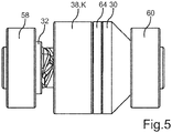
- bearings 58 and 60 spaced apart from one another and designed as roller bearings, for example, are provided in the axial direction of the drive motor 12, the coupling element 38 and the driver element 30 being arranged between the bearings 58 and 60 in the axial direction.
- the coupling 22 is mounted on the housing 18, in particular in the radial direction and in the axial direction.
- the bearings 58 and 60 limit one or the movement of the coupling element 38 along the actuation axis of rotation 34 in the direction of the actuation element 32 or the drive motor 12 and in the opposite direction and thus in the direction of the driver element 30 or the threaded spindle 24.
- the door drive 10 also has a further bearing 62 functioning as a spindle bearing, by means of which, for example, the threaded spindle 24 is mounted on the housing 18 in the radial direction and / or in the axial direction. While the in Figs. 1 to 4 The first embodiment shown, the driver element 30 and the coupling element 38 cooperate in the coupling position K in a form-fitting manner and are thus coupled to one another in a form-fitting manner in a torque-transmitting manner Fig.
- a clutch friction lining 64 is provided, for example, which is held, for example, on the driver element 30 or on the clutch element 38.
- the actuating element 32 is rotated about the actuating axis of rotation 34 in a first direction of rotation by means of the drive motor 12. This is brought about, for example, by a corresponding operation by a human user, that is to say a person, that is, initiated or caused.
- the actuating element 32 is automatically activated by means of the drive motor 12, i.e.
Landscapes
- Engineering & Computer Science (AREA)
- General Engineering & Computer Science (AREA)
- Mechanical Engineering (AREA)
- Power-Operated Mechanisms For Wings (AREA)
Priority Applications (4)
| Application Number | Priority Date | Filing Date | Title |
|---|---|---|---|
| ES19425052T ES2918386T3 (es) | 2019-07-15 | 2019-07-15 | Accionamiento de puerta para una puerta, en particular de un mueble o de un aparato, método para el funcionamiento de un tal accionamiento de puerta y dispositivo con al menos un tal accionamiento de puerta |
| EP19425052.8A EP3767061B1 (fr) | 2019-07-15 | 2019-07-15 | Entraînement pour une porte, en particulier d'un meuble ou d'un appareil, procédé de fonctionnement d'un tel entraînement de porte ainsi que dispositif doté d'au moins un tel entraînement de porte |
| US16/920,944 US11499358B2 (en) | 2019-07-15 | 2020-07-06 | Door drive for a door, in particular of a piece of furniture or an appliance, method for operating such a door drive as well as device with at least one such door drive |
| CN202010681035.1A CN112227869B (zh) | 2019-07-15 | 2020-07-15 | 用于家具或器具的门的门驱动器、用于运行门驱动器的方法和带有至少一个门驱动器的装置 |
Applications Claiming Priority (1)
| Application Number | Priority Date | Filing Date | Title |
|---|---|---|---|
| EP19425052.8A EP3767061B1 (fr) | 2019-07-15 | 2019-07-15 | Entraînement pour une porte, en particulier d'un meuble ou d'un appareil, procédé de fonctionnement d'un tel entraînement de porte ainsi que dispositif doté d'au moins un tel entraînement de porte |
Publications (2)
| Publication Number | Publication Date |
|---|---|
| EP3767061A1 true EP3767061A1 (fr) | 2021-01-20 |
| EP3767061B1 EP3767061B1 (fr) | 2022-05-04 |
Family
ID=67847667
Family Applications (1)
| Application Number | Title | Priority Date | Filing Date |
|---|---|---|---|
| EP19425052.8A Active EP3767061B1 (fr) | 2019-07-15 | 2019-07-15 | Entraînement pour une porte, en particulier d'un meuble ou d'un appareil, procédé de fonctionnement d'un tel entraînement de porte ainsi que dispositif doté d'au moins un tel entraînement de porte |
Country Status (4)
| Country | Link |
|---|---|
| US (1) | US11499358B2 (fr) |
| EP (1) | EP3767061B1 (fr) |
| CN (1) | CN112227869B (fr) |
| ES (1) | ES2918386T3 (fr) |
Cited By (3)
| Publication number | Priority date | Publication date | Assignee | Title |
|---|---|---|---|---|
| EP4047164A1 (fr) * | 2021-02-18 | 2022-08-24 | Apparatebau Gronbach S.R.L. | Dispositif d'entraînement pour un appareil, agencement, ainsi qu'appareil électroménager |
| DE102021109715C5 (de) * | 2021-04-16 | 2025-02-27 | Bayerische Motoren Werke Aktiengesellschaft | Aktivierbare Antriebsvorrichtung |
| US12523082B2 (en) | 2021-04-16 | 2026-01-13 | Edscha Engineering Gmbh | Activatable drive device |
Families Citing this family (1)
| Publication number | Priority date | Publication date | Assignee | Title |
|---|---|---|---|---|
| US20230049706A1 (en) * | 2021-08-11 | 2023-02-16 | Hi-Lex Controls, Inc. | Power actuator for automotive passenger door |
Citations (3)
| Publication number | Priority date | Publication date | Assignee | Title |
|---|---|---|---|---|
| EP2148035A2 (fr) | 2008-07-24 | 2010-01-27 | SUSPA Holding GmbH | Dispositif d'entraînement pour portes de réfrigérateur |
| DE102016113353A1 (de) * | 2016-07-20 | 2018-01-25 | Brose Fahrzeugteile Gmbh & Co. Kg, Bamberg | Antriebsanordnung einer Verschlusselementanordnung |
| US20190040670A1 (en) * | 2017-08-04 | 2019-02-07 | Faringosi Hinges S.R.L. | Motorized hinge |
Family Cites Families (7)
| Publication number | Priority date | Publication date | Assignee | Title |
|---|---|---|---|---|
| US3690427A (en) * | 1970-09-10 | 1972-09-12 | Int Harvester Co | Positive shifted jaw clutch |
| JPS6095228A (ja) * | 1983-10-29 | 1985-05-28 | Matsushita Electric Ind Co Ltd | プラスチツクブレ−キシユ− |
| DE102007020826B4 (de) * | 2007-05-02 | 2019-01-03 | Stabilus Gmbh | Antriebseinrichtung |
| CN106714981A (zh) * | 2014-09-23 | 2017-05-24 | Sika技术股份公司 | 用于材料的施加装置 |
| US10648231B2 (en) * | 2016-01-14 | 2020-05-12 | Hunter Douglas, Inc. | Methods and apparatus for controlling architectural opening coverings in more than one mode |
| DE102016116876A1 (de) | 2016-09-08 | 2018-03-08 | Brose Fahrzeugteile Gmbh & Co. Kg, Bamberg | Antriebsanordnung |
| CN106761141B (zh) | 2017-03-07 | 2019-03-26 | 上海胜华波汽车电器有限公司 | 具有过载保护功能的电动撑杆 |
-
2019
- 2019-07-15 ES ES19425052T patent/ES2918386T3/es active Active
- 2019-07-15 EP EP19425052.8A patent/EP3767061B1/fr active Active
-
2020
- 2020-07-06 US US16/920,944 patent/US11499358B2/en active Active
- 2020-07-15 CN CN202010681035.1A patent/CN112227869B/zh active Active
Patent Citations (3)
| Publication number | Priority date | Publication date | Assignee | Title |
|---|---|---|---|---|
| EP2148035A2 (fr) | 2008-07-24 | 2010-01-27 | SUSPA Holding GmbH | Dispositif d'entraînement pour portes de réfrigérateur |
| DE102016113353A1 (de) * | 2016-07-20 | 2018-01-25 | Brose Fahrzeugteile Gmbh & Co. Kg, Bamberg | Antriebsanordnung einer Verschlusselementanordnung |
| US20190040670A1 (en) * | 2017-08-04 | 2019-02-07 | Faringosi Hinges S.R.L. | Motorized hinge |
Cited By (3)
| Publication number | Priority date | Publication date | Assignee | Title |
|---|---|---|---|---|
| EP4047164A1 (fr) * | 2021-02-18 | 2022-08-24 | Apparatebau Gronbach S.R.L. | Dispositif d'entraînement pour un appareil, agencement, ainsi qu'appareil électroménager |
| DE102021109715C5 (de) * | 2021-04-16 | 2025-02-27 | Bayerische Motoren Werke Aktiengesellschaft | Aktivierbare Antriebsvorrichtung |
| US12523082B2 (en) | 2021-04-16 | 2026-01-13 | Edscha Engineering Gmbh | Activatable drive device |
Also Published As
| Publication number | Publication date |
|---|---|
| US20210017801A1 (en) | 2021-01-21 |
| EP3767061B1 (fr) | 2022-05-04 |
| US11499358B2 (en) | 2022-11-15 |
| CN112227869A (zh) | 2021-01-15 |
| ES2918386T3 (es) | 2022-07-15 |
| CN112227869B (zh) | 2022-04-19 |
Similar Documents
| Publication | Publication Date | Title |
|---|---|---|
| EP3516251B1 (fr) | Système d'actionnement et dispositif embrayage pour un véhicule automobile | |
| EP3767061B1 (fr) | Entraînement pour une porte, en particulier d'un meuble ou d'un appareil, procédé de fonctionnement d'un tel entraînement de porte ainsi que dispositif doté d'au moins un tel entraînement de porte | |
| DE102007020826B4 (de) | Antriebseinrichtung | |
| EP3508676B1 (fr) | Charnière pour un appareil électroménager | |
| WO1999042739A1 (fr) | Frein a disque a commande electromagnetique | |
| EP2098743A1 (fr) | Mécanisme de réglage destiné à l'insertion et l'extraction d'un embrayage de coupure à l'aide d'un segment de came rotatif | |
| WO2003093695A1 (fr) | Frein hydrodynamique | |
| DE102021120210B4 (de) | Antriebsvorrichtung für eine verstellbare Fahrzeugklappe | |
| DE102021203008A1 (de) | Betätigungseinrichtung für eine elektromechanisch betätigbare Kraftfahrzeugbremse | |
| EP1143160A2 (fr) | Ensemble à embrayage double | |
| DE102009036872B4 (de) | Türeinheit | |
| DE102012006097A1 (de) | Zuspannvorrichtung für eine drehhebelbetätigte Scheibenbremse | |
| DE102006045163A1 (de) | Doppelkupplung für ein Doppelkupplungsgetriebe | |
| EP0716242B1 (fr) | Actionnement à moteur électrique d'un embrayage à friction | |
| DE102019130202B4 (de) | Mehrscheiben-Kupplungseinrichtung, Hybridmodul und Antriebsanordnung | |
| DE102005014633A1 (de) | Kupplungsaktorik und Verfahren zum Betätigen zumindest einer Kupplung in einem Antriebsstrang eines Fahrzeugs | |
| EP1586784A1 (fr) | Méthode et actionneur d'embrayage pour actionner au moins un embrayage dans une transmission d'un véhicule | |
| DE102009057330A1 (de) | Elektromechanische Bremse für ein Kraftfahrzeug | |
| DE10029708A1 (de) | Bremsvorrichtung für ein Fahrzeug | |
| WO2021089218A1 (fr) | Embrayage à friction conique doté d'un actionneur et d'un levier pour débrayer l'embrayage | |
| DE10257865A1 (de) | Vorrichtung zum Betätigen von Fahrzeugbremsen | |
| DE102023111774B4 (de) | Verstellaktuator für Lenkeinrichtung | |
| DE102019100969B4 (de) | Trockendoppelkupplung für eine elektrische Achse sowie elektrische Achse mit der Trockendoppelkupplung | |
| DE102019115904A1 (de) | Hybridmodul mit Trennkupplung und Betätigungseinheit ohne Kompensation; sowie Antriebsstrang | |
| DE10238117B4 (de) | Einrückeranordnung zur Erzeugung einer Einrückkraft für eine Reibungskupplung |
Legal Events
| Date | Code | Title | Description |
|---|---|---|---|
| PUAI | Public reference made under article 153(3) epc to a published international application that has entered the european phase |
Free format text: ORIGINAL CODE: 0009012 |
|
| STAA | Information on the status of an ep patent application or granted ep patent |
Free format text: STATUS: THE APPLICATION HAS BEEN PUBLISHED |
|
| AK | Designated contracting states |
Kind code of ref document: A1 Designated state(s): AL AT BE BG CH CY CZ DE DK EE ES FI FR GB GR HR HU IE IS IT LI LT LU LV MC MK MT NL NO PL PT RO RS SE SI SK SM TR |
|
| AX | Request for extension of the european patent |
Extension state: BA ME |
|
| STAA | Information on the status of an ep patent application or granted ep patent |
Free format text: STATUS: REQUEST FOR EXAMINATION WAS MADE |
|
| 17P | Request for examination filed |
Effective date: 20210709 |
|
| RBV | Designated contracting states (corrected) |
Designated state(s): AL AT BE BG CH CY CZ DE DK EE ES FI FR GB GR HR HU IE IS IT LI LT LU LV MC MK MT NL NO PL PT RO RS SE SI SK SM TR |
|
| GRAP | Despatch of communication of intention to grant a patent |
Free format text: ORIGINAL CODE: EPIDOSNIGR1 |
|
| STAA | Information on the status of an ep patent application or granted ep patent |
Free format text: STATUS: GRANT OF PATENT IS INTENDED |
|
| RIC1 | Information provided on ipc code assigned before grant |
Ipc: F16D 11/04 20060101ALI20211123BHEP Ipc: E05F 15/622 20150101AFI20211123BHEP |
|
| INTG | Intention to grant announced |
Effective date: 20211221 |
|
| GRAS | Grant fee paid |
Free format text: ORIGINAL CODE: EPIDOSNIGR3 |
|
| GRAA | (expected) grant |
Free format text: ORIGINAL CODE: 0009210 |
|
| STAA | Information on the status of an ep patent application or granted ep patent |
Free format text: STATUS: THE PATENT HAS BEEN GRANTED |
|
| AK | Designated contracting states |
Kind code of ref document: B1 Designated state(s): AL AT BE BG CH CY CZ DE DK EE ES FI FR GB GR HR HU IE IS IT LI LT LU LV MC MK MT NL NO PL PT RO RS SE SI SK SM TR |
|
| REG | Reference to a national code |
Ref country code: GB Ref legal event code: FG4D Free format text: NOT ENGLISH |
|
| REG | Reference to a national code |
Ref country code: CH Ref legal event code: EP |
|
| REG | Reference to a national code |
Ref country code: AT Ref legal event code: REF Ref document number: 1489213 Country of ref document: AT Kind code of ref document: T Effective date: 20220515 |
|
| REG | Reference to a national code |
Ref country code: DE Ref legal event code: R096 Ref document number: 502019004259 Country of ref document: DE |
|
| REG | Reference to a national code |
Ref country code: IE Ref legal event code: FG4D Free format text: LANGUAGE OF EP DOCUMENT: GERMAN |
|
| REG | Reference to a national code |
Ref country code: ES Ref legal event code: FG2A Ref document number: 2918386 Country of ref document: ES Kind code of ref document: T3 Effective date: 20220715 |
|
| REG | Reference to a national code |
Ref country code: LT Ref legal event code: MG9D |
|
| REG | Reference to a national code |
Ref country code: NL Ref legal event code: MP Effective date: 20220504 |
|
| PG25 | Lapsed in a contracting state [announced via postgrant information from national office to epo] |
Ref country code: SE Free format text: LAPSE BECAUSE OF FAILURE TO SUBMIT A TRANSLATION OF THE DESCRIPTION OR TO PAY THE FEE WITHIN THE PRESCRIBED TIME-LIMIT Effective date: 20220504 Ref country code: PT Free format text: LAPSE BECAUSE OF FAILURE TO SUBMIT A TRANSLATION OF THE DESCRIPTION OR TO PAY THE FEE WITHIN THE PRESCRIBED TIME-LIMIT Effective date: 20220905 Ref country code: NO Free format text: LAPSE BECAUSE OF FAILURE TO SUBMIT A TRANSLATION OF THE DESCRIPTION OR TO PAY THE FEE WITHIN THE PRESCRIBED TIME-LIMIT Effective date: 20220804 Ref country code: NL Free format text: LAPSE BECAUSE OF FAILURE TO SUBMIT A TRANSLATION OF THE DESCRIPTION OR TO PAY THE FEE WITHIN THE PRESCRIBED TIME-LIMIT Effective date: 20220504 Ref country code: LT Free format text: LAPSE BECAUSE OF FAILURE TO SUBMIT A TRANSLATION OF THE DESCRIPTION OR TO PAY THE FEE WITHIN THE PRESCRIBED TIME-LIMIT Effective date: 20220504 Ref country code: HR Free format text: LAPSE BECAUSE OF FAILURE TO SUBMIT A TRANSLATION OF THE DESCRIPTION OR TO PAY THE FEE WITHIN THE PRESCRIBED TIME-LIMIT Effective date: 20220504 Ref country code: GR Free format text: LAPSE BECAUSE OF FAILURE TO SUBMIT A TRANSLATION OF THE DESCRIPTION OR TO PAY THE FEE WITHIN THE PRESCRIBED TIME-LIMIT Effective date: 20220805 Ref country code: FI Free format text: LAPSE BECAUSE OF FAILURE TO SUBMIT A TRANSLATION OF THE DESCRIPTION OR TO PAY THE FEE WITHIN THE PRESCRIBED TIME-LIMIT Effective date: 20220504 Ref country code: BG Free format text: LAPSE BECAUSE OF FAILURE TO SUBMIT A TRANSLATION OF THE DESCRIPTION OR TO PAY THE FEE WITHIN THE PRESCRIBED TIME-LIMIT Effective date: 20220804 |
|
| PG25 | Lapsed in a contracting state [announced via postgrant information from national office to epo] |
Ref country code: RS Free format text: LAPSE BECAUSE OF FAILURE TO SUBMIT A TRANSLATION OF THE DESCRIPTION OR TO PAY THE FEE WITHIN THE PRESCRIBED TIME-LIMIT Effective date: 20220504 Ref country code: PL Free format text: LAPSE BECAUSE OF FAILURE TO SUBMIT A TRANSLATION OF THE DESCRIPTION OR TO PAY THE FEE WITHIN THE PRESCRIBED TIME-LIMIT Effective date: 20220504 Ref country code: LV Free format text: LAPSE BECAUSE OF FAILURE TO SUBMIT A TRANSLATION OF THE DESCRIPTION OR TO PAY THE FEE WITHIN THE PRESCRIBED TIME-LIMIT Effective date: 20220504 Ref country code: IS Free format text: LAPSE BECAUSE OF FAILURE TO SUBMIT A TRANSLATION OF THE DESCRIPTION OR TO PAY THE FEE WITHIN THE PRESCRIBED TIME-LIMIT Effective date: 20220904 |
|
| PG25 | Lapsed in a contracting state [announced via postgrant information from national office to epo] |
Ref country code: SM Free format text: LAPSE BECAUSE OF FAILURE TO SUBMIT A TRANSLATION OF THE DESCRIPTION OR TO PAY THE FEE WITHIN THE PRESCRIBED TIME-LIMIT Effective date: 20220504 Ref country code: SK Free format text: LAPSE BECAUSE OF FAILURE TO SUBMIT A TRANSLATION OF THE DESCRIPTION OR TO PAY THE FEE WITHIN THE PRESCRIBED TIME-LIMIT Effective date: 20220504 Ref country code: RO Free format text: LAPSE BECAUSE OF FAILURE TO SUBMIT A TRANSLATION OF THE DESCRIPTION OR TO PAY THE FEE WITHIN THE PRESCRIBED TIME-LIMIT Effective date: 20220504 Ref country code: EE Free format text: LAPSE BECAUSE OF FAILURE TO SUBMIT A TRANSLATION OF THE DESCRIPTION OR TO PAY THE FEE WITHIN THE PRESCRIBED TIME-LIMIT Effective date: 20220504 Ref country code: DK Free format text: LAPSE BECAUSE OF FAILURE TO SUBMIT A TRANSLATION OF THE DESCRIPTION OR TO PAY THE FEE WITHIN THE PRESCRIBED TIME-LIMIT Effective date: 20220504 Ref country code: CZ Free format text: LAPSE BECAUSE OF FAILURE TO SUBMIT A TRANSLATION OF THE DESCRIPTION OR TO PAY THE FEE WITHIN THE PRESCRIBED TIME-LIMIT Effective date: 20220504 |
|
| REG | Reference to a national code |
Ref country code: DE Ref legal event code: R097 Ref document number: 502019004259 Country of ref document: DE |
|
| PG25 | Lapsed in a contracting state [announced via postgrant information from national office to epo] |
Ref country code: MC Free format text: LAPSE BECAUSE OF FAILURE TO SUBMIT A TRANSLATION OF THE DESCRIPTION OR TO PAY THE FEE WITHIN THE PRESCRIBED TIME-LIMIT Effective date: 20220504 |
|
| REG | Reference to a national code |
Ref country code: CH Ref legal event code: PL |
|
| PLBE | No opposition filed within time limit |
Free format text: ORIGINAL CODE: 0009261 |
|
| STAA | Information on the status of an ep patent application or granted ep patent |
Free format text: STATUS: NO OPPOSITION FILED WITHIN TIME LIMIT |
|
| REG | Reference to a national code |
Ref country code: BE Ref legal event code: MM Effective date: 20220731 |
|
| PG25 | Lapsed in a contracting state [announced via postgrant information from national office to epo] |
Ref country code: AL Free format text: LAPSE BECAUSE OF FAILURE TO SUBMIT A TRANSLATION OF THE DESCRIPTION OR TO PAY THE FEE WITHIN THE PRESCRIBED TIME-LIMIT Effective date: 20220504 |
|
| 26N | No opposition filed |
Effective date: 20230207 |
|
| PG25 | Lapsed in a contracting state [announced via postgrant information from national office to epo] |
Ref country code: LU Free format text: LAPSE BECAUSE OF NON-PAYMENT OF DUE FEES Effective date: 20220715 Ref country code: LI Free format text: LAPSE BECAUSE OF NON-PAYMENT OF DUE FEES Effective date: 20220731 Ref country code: FR Free format text: LAPSE BECAUSE OF NON-PAYMENT OF DUE FEES Effective date: 20220731 Ref country code: CH Free format text: LAPSE BECAUSE OF NON-PAYMENT OF DUE FEES Effective date: 20220731 |
|
| PG25 | Lapsed in a contracting state [announced via postgrant information from national office to epo] |
Ref country code: BE Free format text: LAPSE BECAUSE OF NON-PAYMENT OF DUE FEES Effective date: 20220731 |
|
| P01 | Opt-out of the competence of the unified patent court (upc) registered |
Effective date: 20230526 |
|
| PG25 | Lapsed in a contracting state [announced via postgrant information from national office to epo] |
Ref country code: IE Free format text: LAPSE BECAUSE OF NON-PAYMENT OF DUE FEES Effective date: 20220715 |
|
| GBPC | Gb: european patent ceased through non-payment of renewal fee |
Effective date: 20230715 |
|
| PG25 | Lapsed in a contracting state [announced via postgrant information from national office to epo] |
Ref country code: MK Free format text: LAPSE BECAUSE OF FAILURE TO SUBMIT A TRANSLATION OF THE DESCRIPTION OR TO PAY THE FEE WITHIN THE PRESCRIBED TIME-LIMIT Effective date: 20220504 Ref country code: CY Free format text: LAPSE BECAUSE OF FAILURE TO SUBMIT A TRANSLATION OF THE DESCRIPTION OR TO PAY THE FEE WITHIN THE PRESCRIBED TIME-LIMIT Effective date: 20220504 Ref country code: GB Free format text: LAPSE BECAUSE OF NON-PAYMENT OF DUE FEES Effective date: 20230715 |
|
| PG25 | Lapsed in a contracting state [announced via postgrant information from national office to epo] |
Ref country code: HU Free format text: LAPSE BECAUSE OF FAILURE TO SUBMIT A TRANSLATION OF THE DESCRIPTION OR TO PAY THE FEE WITHIN THE PRESCRIBED TIME-LIMIT; INVALID AB INITIO Effective date: 20190715 |
|
| PG25 | Lapsed in a contracting state [announced via postgrant information from national office to epo] |
Ref country code: MT Free format text: LAPSE BECAUSE OF FAILURE TO SUBMIT A TRANSLATION OF THE DESCRIPTION OR TO PAY THE FEE WITHIN THE PRESCRIBED TIME-LIMIT Effective date: 20220504 |
|
| PG25 | Lapsed in a contracting state [announced via postgrant information from national office to epo] |
Ref country code: BG Free format text: LAPSE BECAUSE OF FAILURE TO SUBMIT A TRANSLATION OF THE DESCRIPTION OR TO PAY THE FEE WITHIN THE PRESCRIBED TIME-LIMIT Effective date: 20220504 |
|
| PG25 | Lapsed in a contracting state [announced via postgrant information from national office to epo] |
Ref country code: BG Free format text: LAPSE BECAUSE OF FAILURE TO SUBMIT A TRANSLATION OF THE DESCRIPTION OR TO PAY THE FEE WITHIN THE PRESCRIBED TIME-LIMIT Effective date: 20220504 |
|
| PGFP | Annual fee paid to national office [announced via postgrant information from national office to epo] |
Ref country code: SI Payment date: 20250709 Year of fee payment: 7 |
|
| REG | Reference to a national code |
Ref country code: AT Ref legal event code: MM01 Ref document number: 1489213 Country of ref document: AT Kind code of ref document: T Effective date: 20240715 |
|
| PGFP | Annual fee paid to national office [announced via postgrant information from national office to epo] |
Ref country code: ES Payment date: 20250819 Year of fee payment: 7 |
|
| PGFP | Annual fee paid to national office [announced via postgrant information from national office to epo] |
Ref country code: DE Payment date: 20250724 Year of fee payment: 7 |
|
| PGFP | Annual fee paid to national office [announced via postgrant information from national office to epo] |
Ref country code: TR Payment date: 20250710 Year of fee payment: 7 Ref country code: IT Payment date: 20250731 Year of fee payment: 7 |
|
| PG25 | Lapsed in a contracting state [announced via postgrant information from national office to epo] |
Ref country code: AT Free format text: LAPSE BECAUSE OF NON-PAYMENT OF DUE FEES Effective date: 20240715 |
|
| PGFP | Annual fee paid to national office [announced via postgrant information from national office to epo] |
Ref country code: AT Payment date: 20260410 Year of fee payment: 5 |