EP3767258A1 - Dispositif de détection de longueur d'onde et dispositif de mesure confocal - Google Patents
Dispositif de détection de longueur d'onde et dispositif de mesure confocal Download PDFInfo
- Publication number
- EP3767258A1 EP3767258A1 EP19766776.9A EP19766776A EP3767258A1 EP 3767258 A1 EP3767258 A1 EP 3767258A1 EP 19766776 A EP19766776 A EP 19766776A EP 3767258 A1 EP3767258 A1 EP 3767258A1
- Authority
- EP
- European Patent Office
- Prior art keywords
- light
- wavelength
- transmittance
- optical filters
- detection device
- Prior art date
- Legal status (The legal status is an assumption and is not a legal conclusion. Google has not performed a legal analysis and makes no representation as to the accuracy of the status listed.)
- Pending
Links
- 238000001514 detection method Methods 0.000 title claims abstract description 74
- 238000005259 measurement Methods 0.000 title claims description 55
- 238000002834 transmittance Methods 0.000 claims abstract description 185
- 230000003287 optical effect Effects 0.000 claims abstract description 104
- 238000004364 calculation method Methods 0.000 claims abstract description 17
- 230000004075 alteration Effects 0.000 claims description 18
- 238000006073 displacement reaction Methods 0.000 claims description 12
- 230000007423 decrease Effects 0.000 claims description 7
- 239000000758 substrate Substances 0.000 claims description 5
- 238000004611 spectroscopical analysis Methods 0.000 abstract description 4
- 230000002708 enhancing effect Effects 0.000 abstract description 2
- 239000000835 fiber Substances 0.000 description 17
- 238000010586 diagram Methods 0.000 description 5
- 230000001965 increasing effect Effects 0.000 description 4
- 238000000034 method Methods 0.000 description 4
- 230000000737 periodic effect Effects 0.000 description 3
- 230000008020 evaporation Effects 0.000 description 2
- 238000001704 evaporation Methods 0.000 description 2
- 230000001678 irradiating effect Effects 0.000 description 2
- 230000005540 biological transmission Effects 0.000 description 1
- BJQHLKABXJIVAM-UHFFFAOYSA-N bis(2-ethylhexyl) phthalate Chemical compound CCCCC(CC)COC(=O)C1=CC=CC=C1C(=O)OCC(CC)CCCC BJQHLKABXJIVAM-UHFFFAOYSA-N 0.000 description 1
- 230000006866 deterioration Effects 0.000 description 1
- 230000000694 effects Effects 0.000 description 1
- 239000011521 glass Substances 0.000 description 1
- 238000004088 simulation Methods 0.000 description 1
Images




Classifications
-
- G—PHYSICS
- G01—MEASURING; TESTING
- G01J—MEASUREMENT OF INTENSITY, VELOCITY, SPECTRAL CONTENT, POLARISATION, PHASE OR PULSE CHARACTERISTICS OF INFRARED, VISIBLE OR ULTRAVIOLET LIGHT; COLORIMETRY; RADIATION PYROMETRY
- G01J3/00—Spectrometry; Spectrophotometry; Monochromators; Measuring colours
- G01J3/12—Generating the spectrum; Monochromators
- G01J3/26—Generating the spectrum; Monochromators using multiple reflection, e.g. Fabry-Perot interferometer, variable interference filters
-
- G—PHYSICS
- G01—MEASURING; TESTING
- G01J—MEASUREMENT OF INTENSITY, VELOCITY, SPECTRAL CONTENT, POLARISATION, PHASE OR PULSE CHARACTERISTICS OF INFRARED, VISIBLE OR ULTRAVIOLET LIGHT; COLORIMETRY; RADIATION PYROMETRY
- G01J9/00—Measuring optical phase difference; Determining degree of coherence; Measuring optical wavelength
- G01J9/02—Measuring optical phase difference; Determining degree of coherence; Measuring optical wavelength by interferometric methods
- G01J9/0246—Measuring optical wavelength
-
- G—PHYSICS
- G01—MEASURING; TESTING
- G01B—MEASURING LENGTH, THICKNESS OR SIMILAR LINEAR DIMENSIONS; MEASURING ANGLES; MEASURING AREAS; MEASURING IRREGULARITIES OF SURFACES OR CONTOURS
- G01B11/00—Measuring arrangements characterised by the use of optical techniques
-
- G—PHYSICS
- G01—MEASURING; TESTING
- G01B—MEASURING LENGTH, THICKNESS OR SIMILAR LINEAR DIMENSIONS; MEASURING ANGLES; MEASURING AREAS; MEASURING IRREGULARITIES OF SURFACES OR CONTOURS
- G01B11/00—Measuring arrangements characterised by the use of optical techniques
- G01B11/02—Measuring arrangements characterised by the use of optical techniques for measuring length, width or thickness
- G01B11/06—Measuring arrangements characterised by the use of optical techniques for measuring length, width or thickness for measuring thickness ; e.g. of sheet material
- G01B11/0608—Height gauges
-
- G—PHYSICS
- G01—MEASURING; TESTING
- G01J—MEASUREMENT OF INTENSITY, VELOCITY, SPECTRAL CONTENT, POLARISATION, PHASE OR PULSE CHARACTERISTICS OF INFRARED, VISIBLE OR ULTRAVIOLET LIGHT; COLORIMETRY; RADIATION PYROMETRY
- G01J3/00—Spectrometry; Spectrophotometry; Monochromators; Measuring colours
- G01J3/28—Investigating the spectrum
- G01J3/30—Measuring the intensity of spectral lines directly on the spectrum itself
- G01J3/36—Investigating two or more bands of a spectrum by separate detectors
-
- G—PHYSICS
- G01—MEASURING; TESTING
- G01J—MEASUREMENT OF INTENSITY, VELOCITY, SPECTRAL CONTENT, POLARISATION, PHASE OR PULSE CHARACTERISTICS OF INFRARED, VISIBLE OR ULTRAVIOLET LIGHT; COLORIMETRY; RADIATION PYROMETRY
- G01J3/00—Spectrometry; Spectrophotometry; Monochromators; Measuring colours
- G01J3/46—Measurement of colour; Colour measuring devices, e.g. colorimeters
- G01J3/50—Measurement of colour; Colour measuring devices, e.g. colorimeters using electric radiation detectors
- G01J3/51—Measurement of colour; Colour measuring devices, e.g. colorimeters using electric radiation detectors using colour filters
-
- G—PHYSICS
- G01—MEASURING; TESTING
- G01J—MEASUREMENT OF INTENSITY, VELOCITY, SPECTRAL CONTENT, POLARISATION, PHASE OR PULSE CHARACTERISTICS OF INFRARED, VISIBLE OR ULTRAVIOLET LIGHT; COLORIMETRY; RADIATION PYROMETRY
- G01J9/00—Measuring optical phase difference; Determining degree of coherence; Measuring optical wavelength
-
- G—PHYSICS
- G01—MEASURING; TESTING
- G01B—MEASURING LENGTH, THICKNESS OR SIMILAR LINEAR DIMENSIONS; MEASURING ANGLES; MEASURING AREAS; MEASURING IRREGULARITIES OF SURFACES OR CONTOURS
- G01B2210/00—Aspects not specifically covered by any group under G01B, e.g. of wheel alignment, caliper-like sensors
- G01B2210/50—Using chromatic effects to achieve wavelength-dependent depth resolution
Definitions
- the present invention relates to a wavelength detection device that detects the wavelength of light and a confocal measurement device that includes the wavelength detection device.
- a confocal measurement device that measures the displacement of the measurement object using a confocal optical system is disclosed in patent literature 1.
- the confocal measurement device disclosed in patent literature 1 has a white LED 21, a diffractive lens 1 that generates chromatic aberration in the light emitted from the white LED 21 along the optical axis direction, an objective lens 2 which is arranged closer to the measurement object 200 side than the diffractive lens 1 and which condenses the light having the chromatic aberration generated by the diffraction lens 1 on the measurement object 200, a pinhole that allows the light focused in the measurement object 200 among the light condensed by the objective lens 2 to pass through, and a wavelength measurement portion that measures the wavelength of the light that has passed through the pinhole.
- the focal length of the diffractive lens 1 is set to be longer than the difference between the distance from the diffractive lens 1 to the objective lens 2 and the focal length of the objective lens 2.
- incident light 100 of an optical signal is distributed into a plurality of lights by an optical distributor 101, and a part of the distributed plurality of lights is transmitted through an optical filter 103 having different transmission ratios due to the incident wavelengths, and the transmitted light and the non-transmitted light that does not pass through the optical filter 103 are received by the light receivers 105 and 107 to be converted into voltage signals.
- the comparison calculator 109 calculates the ratio of the light intensities of the transmitted light and the non-transmitted light based on the voltage signals, and calculates the wavelength of the incident light 100 based on the intensity ratio.
- the displacement is measured using a diffraction grating and a line CMOS.
- the line CMOS it takes a long time to read out the CMOS information, which causes a problem that the measurement time becomes long. From the point above, it is advantageous to adopt a spectroscopic method using an optical filter.
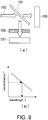
- the basic principle of the optical wavelength monitor device described in patent literature 2 can be explained as shown in FIG 9 . That is, in the optical wavelength monitor, the incident light is divided into a plurality of lights by the optical distributor 101 such as an optical filter. Then, one of the lights passes through the optical filter 103 in which the relationship between the wavelength of light and the transmittance is known, and the intensity is detected by the light receiver 107. The intensity of the other light is detected by the light receiver 105 without passing through an optical filter. Then, for example, by dividing the output of the light receiver 107 by the output of the light receiver 105, the transmittance T of the light is derived. The wavelength of the incident light is derived from the derived transmittance T of the light and the known relationship between the wavelength of the light and the transmittance as shown in (b) of FIG. 9 .
- the wavelength detection precision ⁇ can be expressed by the following equation (1).
- [Mathematical formula 1] ⁇ 1 SN T 2 + 1 dT d ⁇ ⁇ 1
- SN the SN ratio of the light receiver without any optical filter
- T the transmittance
- ⁇ the wavelength. That is, the precision of wavelength detection is inversely proportional to the inclination (dT/d ⁇ ) of the change in the transmittance T with respect to the change in the wavelength ⁇ in the optical filter 103. Therefore, if (dT/d ⁇ ) is increased to improve the precision of wavelength detection, the measurable range of the wavelength would become narrow, and it is difficult to balance the measurable range of wavelength.
- the present invention is accomplished based on the above described problems, and the purpose of the present invention is to provide a technique capable of maintaining a wide wavelength range to be measured and enhancing wavelength detection precision in a wavelength detection device using a spectroscopic method employing an optical filter.
- the present invention for solving the above described problems is a wavelength detection device, including:
- the wavelength detection device of the present invention divides light and allows the split lights to pass through the plurality of optical filters or be reflected by the plurality of optical filters. Then, the plurality of light receiving elements detect the intensities of the lights that have passed through each of the plurality of optical filters or reflected by each of the plurality of optical filters. Then, the calculation portion derives a physical quantity related to the transmittances of the plurality of optical filters from the outputs of the plurality of light receiving elements, and derives the wavelengths of the lights which have passed through the plurality of optical filters on the basis of the known transmittance characteristics of the plurality of optical filters.
- the transmittance characteristic of each optical filter has an inclination portion in different wavelength ranges of the wavelength range to be measured. That is, the plurality of optical filters as a whole have as many inclination portions as the number of the optical filters in different wavelength ranges of the wavelength range to be measured.
- the device it is possible to detect the wavelength of light by using the plurality of inclination portions in the transmittance characteristic arranged in different wavelength ranges. Accordingly, as compared with the case where the wavelength is detected by using the transmittance characteristic having a single inclination portion with respect to the wavelength range to be measured, a wide wavelength range to be measured can be maintained and the inclination angle of the inclination portion can be steeper. Then, the wavelength value can be more clearly specified by detecting the wavelength using the steeper inclination portion in the transmittance characteristic. As a result, it is possible to further improve the precision of wavelength detection.
- the physical quantity related to the transmittance may be transmittance or reflectance.
- the physical quantity related to the transmittance may be a value obtained by dividing the light amount or light intensity after passing through the optical filter by the light amount or light intensity before passing through the optical filter, or may be a value obtained by logarithmically converting the light amount or light intensity before passing through the optical filter and the light amount or light intensity after passing through the optical filter respectively and taking the difference.
- the physical quantity related to the transmittance may be a value obtained by dividing the light amount or light intensity after being reflected by the optical filter by the light amount or light intensity before being reflected by the optical filter, or may be a value obtained by logarithmically converting the light amount or light intensity before being reflected by the optical filter and the light amount or light intensity after being reflected by the optical filter respectively and taking the difference.
- the physical quantity related to the transmittance may be a value obtained by adding a predetermined calculation to the result obtained by each of the above calculations. Further, the physical quantity may be a value derived by another calculation method as long as the value has an equivalent technical meaning.
- the light amount or light intensity before passing through the optical filter or being reflected by the optical filter may be substituted with an equivalent value obtained by another method, such as the light amount or light intensity after passing through the transparent plate.
- the physical quantity related to the transmittance may be transmittance, and in the transmittance characteristic for each of the plurality of optical filters, the transmittance of each of the optical filters may change between approximately 0 and approximately 1 in the inclination portion.
- the steeper inclination portion can be more reliably distributed in the range of 0 to 1 of the transmittance, and it is possible to detect the wavelength more reliably by using the steeper inclination portion with respect to the light of any wavelength of the wavelength range to be measured.
- the physical quantity related to the transmittance may be transmittance, and the absolute value of at least one inclination of the inclination portion may be 0.0033 (1/nm) or more.
- the absolute value of at least one inclination of the inclination portion is 0.0053 (1/nm) or more.
- the inclination portion in the transmittance characteristic of each of the plurality of optical filters may be arranged so as to cover the wavelength range to be measured without any gap.
- any of the above described inclination portions can be used more reliably. Therefore, it is possible to more reliably improve the wavelength detection precision.
- two or more of the transmittance characteristics consist of curves that periodically change in the wavelength range to be measured and the curves related to each of the transmittance characteristics may have different phases.
- the transmittance characteristics of each of the plurality of optical filters may further include a transmittance characteristic consisting of a straight line or a curve that monotonically increases or monotonically decreases in the wavelength range to be measured. That is, when a curve that periodically changes in the wavelength range to be measured is used as the transmittance characteristic, the wavelength can be detected for any wavelength in the wavelength range to be measured, but when the physical quantity related to the specified transmittance is obtained, it may be difficult to determine that the physical quantity related to the transmittance is due to the inclination portion of which cycle.
- the transmittance characteristic consisting of a straight line or a curve that monotonically increases or monotonically decreases in the wavelength range to be measured, it is possible to more reliably determine that the physical quantity related to the transmittance is due to the inclination portion of which cycle, and it is possible to more reliably detect the wavelength of the incident light.
- the plurality of optical filters may be configured by dividing one filter plate into a plurality of regions having different transmittance characteristics, and at least one of the plurality of regions having different transmittance characteristics may be formed of a transparent plate.
- the plurality of light receiving elements may be arranged on the same substrate so as to be able to respectively receive the light transmitted through the plurality of regions.
- the plurality of the light receiving elements may be arranged on the same substrate so as to be able to respectively receive the light transmitted through the plurality of regions.
- the intensity of the light entering the plurality of optical filters and the transparent plate may be non-uniform.
- the intensity of the light entering the plurality of optical filters and the transparent plate may be non-uniform.
- the present invention may be a confocal measurement device, including:
- a confocal measurement device that can detect the wavelength of the incident light with higher precision and thus can measure the displacement of the measurement object more precisely.
- the device can be downsized and the cost can be reduced.
- a wavelength detection device using a spectroscopic method employing an optical filter it is possible to maintain a wide wavelength range to be measured and improve wavelength detection precision.
- the light which enters an incident light fiber 14 is branched into a first branching fiber 14a, a second branching fiber 14b, and a third branching fiber 14c by a branching coupler 11 serving as a splitting unit. Then, the light emitted from each of the first branching fiber 14a, the second branching fiber 14b and the third branching fiber 14c is respectively converted into parallel rays by a first condenser lens 15a, a second condenser lens 15b, and a third condenser lens 15c.
- the light that has passed through the first condenser lens 15a passes through a first filter 12a and then is received by a first light receiving element 13a, and the intensity thereof is converted into an electric signal.
- the light that has passed through the second condenser lens 15b passes through a second filter 12b and then is received by a second light receiving element 13b, and the intensity thereof is converted into an electric signal.
- the light that has passed through the third condenser lens 15c is directly received as reference light by a third light receiving element 13c, and the intensity thereof is converted into an electric signal.
- the intensity of the light received by the first light receiving element 13 a is divided by the intensity of the light received by the third light receiving element 13c, and thereby the transmittance of the first filter 12a is calculated and derived.
- the intensity of the light received by the second light receiving element 13b is divided by the intensity of the light received by the third light receiving element 13c, and thereby the transmittance of the second filter 12b is calculated and derived.
- FIG. 1 shows a relationship between the transmittance and the wavelength of the first filter 12a and the second filter 12b (hereinafter, also referred to as transmittance characteristic).
- the first filter 12a has a characteristic that the transmittance sharply changes from 1 to 0 in the wavelength range of 500 nm to 575 nm, and has a characteristic that all the light is allowed to pass through when the wavelength is shorter than 500 nm (transmittance 1) and no light is allowed to pass through when the wavelength is longer than 575 nm (transmittance 0).
- the second filter 12b has a characteristic that the transmittance sharply changes from 1 to 0 in the wavelength range of 575 nm to 650 nm, and has a characteristic that all the light is allowed to pass through when the wavelength is shorter than 575 nm (transmittance 1) and no light is allowed to pass through when the wavelength is longer than 650 nm (transmittance 0).
- the calculation device 16 detects the wavelength of the incident light according to the transmittance of the light that has passed through the first filter 12a and the transmittance of the light that has passed through the second filter 12b.
- the transmittance of the light that has passed through the first filter 12a is 0, and the transmittance of the light that has passed through the second filter 12b is 0.5.
- the wavelength ⁇ at which the transmittance of the light that has passed through the second filter 12b is 0.5 is derived.
- the calculation device 16 has a table storing a relationship between the wavelength ⁇ , the transmittance of the first filter 12a, and the transmittance of the second filter 12b, the relationship corresponding to the graph of (b) of FIG. 1 .
- the wavelength ⁇ of the incident light is derived according to the table and the values of the transmittance of the light that has passed through the first filter 12a and the transmittance of the light that has passed through the second filter 12b.
- two filters which have transmittance characteristics of having steep inclinations with respect to changes in wavelength in different wavelength ranges of 500 nm to 575 nm and 575 nm to 650 nm are used to detect the wavelength of the incident light. Therefore, it is possible to detect the wavelength in a wide wavelength range of 500 nm to 650 nm by utilizing steep transmittance characteristic.
- the branching coupler 11 splits the incident light into three lights.
- the wavelength range to be measured is measured by using transmittance characteristics of two types of filters, but the number of the filter is not limited to two. The number of the filter may be three types or more.
- the absolute value of the inclination is 0.0133 (1/nm), which is a sufficiently steep inclination.
- the transmittance characteristic of the first filter 12a and the transmittance characteristic of the second filter 12b are arranged without any gap with respect to the wavelength, the wavelength detection is possible with respect to the light having any wavelength in the wavelength range (500 nm to 650 nm) to be measured.
- the transmittance characteristic of the first filter 12a and the transmittance characteristic of the second filter 12b are distributed from 0 to 1 with respect to the transmittance, a steeper transmittance characteristic can be easily realized.
- a confocal measurement device 50 including the wavelength detection device 10 of the present invention is described.
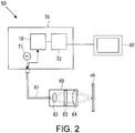
- FIG. 2 is a schematic diagram showing the configuration of the confocal measurement device 50 including the wavelength detection device 10.
- the confocal measurement device 50 shown in FIG. 2 is a measurement device that measures the displacement of the measurement object ob by using a confocal optical system.
- the confocal measuring device 50 includes a head portion 60 having a confocal optical system, a controller portion 70 optically connected through a light fiber 61, and a monitor portion 80 displaying a signal output from the controller portion 70.
- the head portion 60 has a diffractive lens 62 serving as a chromatic aberration imparting unit, and generates chromatic aberration along the optical axis direction in the light emitted from a light source 71 described later (for example, a white light source) that emits lights of a plurality of wavelengths. Then, the light having the chromatic aberration generated by the diffractive lens is condensed on the measurement object ob by an objective lens 64.
- a diffractive lens 62 serving as a chromatic aberration imparting unit, and generates chromatic aberration along the optical axis direction in the light emitted from a light source 71 described later (for example, a white light source) that emits lights of a plurality of wavelengths. Then, the light having the chromatic aberration generated by the diffractive lens is condensed on the measurement object ob by an objective lens 64.
- the light emitted from the light source 71 arranged in the controller portion 70 is guided to the head portion 60 through the light fiber 61.
- the light fiber 61 is a light path from the head portion 60 to the controller portion 70 and also functions as a pinhole 63. That is, among the light condensed by the head portion 60, the light focused on the measurement object ob is focused on the opening portion of the light fiber 61. Therefore, the light fiber 61 functions as the pinhole 63 that blocks light having a wavelength that is not focused on the measurement object ob and allows light that is focused on the measurement object ob to pass through. By using the light fiber 61 in the light path from the head portion 60 to the controller portion 70, it is not necessary to separately arrange a pinhole.
- the confocal measurement device 50 may has a configuration in which a pinhole is separately arranged in the light path from the head portion 60 to the controller portion 70 without using the light fiber 61.
- the controller portion 70 includes the light source 71, which is a white light source, and the wavelength detection device 10.
- a white LED can be illustrated as an example of the light source 71, and another light source may be illustrated as long as it is a light source that can emit white light.
- chromatic aberration is given to the light having a plurality of wavelengths emitted from the light source 71 in the diffractive lens 62 of the head portion 60, and an image is formed on the measurement object ob. Only the light of the wavelength at which an image is accurately formed on the measurement object ob passes through the opening of the light fiber 61 also serving as the pinhole 63, and reaches the controller portion 70 through the light fiber 61. Then, the wavelength is detected by the wavelength detection device 10. Besides, the controller portion 70 is provided with a displacement calculation portion 73 having a table of the relationship between the wavelength of the reflected light from the measurement object ob and the displacement of the measurement object ob. The displacement of the measurement object ob is calculated according to the wavelength measured by the wavelength detection device 10, and the monitor portion 80 displays the result.
- the confocal measurement device 50 in the present example includes the wavelength detection device 10 of the present invention, it is possible to more precisely measure the wavelength of the light imaged and reflected on the measurement object ob. As a result, it is possible to more precisely measure the displacement of the measurement object ob.
- the wavelength detection device used in the confocal measurement device 50 is not limited to the wavelength detection device described in the application example, and may be wavelength detection devices described in following embodiment examples.
- Example 1 of the present invention is described.
- an example is described in which a plurality of filters having different transmittance characteristics are formed on one filter plate, and as for the light receiving element, split light receiving elements obtained by arranging a plurality of light receiving elements on one substrate are used, thereby the structure is further simplified and the number of the inclination portion in the wavelength range to be measured is increased.
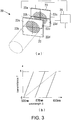
- the configuration of the wavelength detection device 20 in the present example is shown in FIG. 3 .
- the incident light is parallelized by a collimator lens that is not shown.
- the incident light enters a four-division filter 22 without using a branching coupler.
- the incident surface of the filter is divided into four, and filters 22a to 22c having three types of different transmittance characteristics and a transparent plate 22d that allows light of all wavelengths in the wavelength range to be measured to pass through are formed.
- the light that has been parallelized enters and passes through the four-division filter 22 in a manner of evenly entering the filters 22a to 22c and the transparent plate 22d.
- the intensity of the light that has passed through the filters 22a to 22c and the transparent plate 22d is measured.
- the intensity of the light received by the light receiving elements 23a to 23c is divided by the intensity of the light received by the light receiving element 23d, and thereby the transmittance of the light that has passed through the filters 22a to 22c is calculated and derived. Furthermore, in the calculation device 26, the wavelength of the incident light is detected according to the transmittance of the light that has passed through the filters 22a to 22c and the known transmittance characteristic of the filters 22a to 22c. Further, the filters 22a to 22c may be formed on a transparent substrate by evaporation or the like, or may be formed by a color glass filter or a multilayer film filter.
- the filters 22a to 22c and the transparent plate 22d correspond to a plurality of regions.
- the configuration in which the light that has been parallelized enters the four-division filter 22 in a manner of evenly entering the filters 22a to 22c and the transparent plate 22d corresponds to the splitting unit.
- (b) of FIG. 3 shows the transmittance characteristic of the filters 22a to 22c.
- the transmittance characteristic of the filter 22a has a steep inclination portion with respect to the wavelength range of 500 nm to 550 nm.
- the transmittance characteristic of the filter 22b has a steep inclination portion with respect to the wavelength range of 550 nm to 600 nm.
- the transmittance characteristic of the filter 22c has a steep inclination portion with respect to the wavelength range of 600 nm to 650 nm.
- the transmittances of the filters 22a to 22c change from 0 to 1.
- the transmittance characteristic of each of the three filters 22a to 22c has an inclination portion in different wavelength ranges. Further, the absolute value of the inclination of each inclination portion is 0.02 (1/nm), which is sufficiently large, and it is possible to detect the wavelength of light precisely.
- each of the filters 22a to 22c is set to be gentler, it is possible to detect the wavelength of light in a wider wavelength range.
- FIG. 4 shows another example of the transmittance characteristic of the filters 22a to 22c to be used in the wavelength detection device 20.
- the inclination portion when the transmittance increases from 0 to 1 and the inclination portion when the transmittance decreases from 1 to 0 are arranged. Accordingly, it is possible to arrange as many inclination portions as twice the number of filters with respect to the wavelength range to be measured. Then, as shown in FIG. 4 , more inclination portions can be distributed in the wavelength range to be measured, and it is possible to further increase the measurement precision in the wavelength range.
- the transmittance characteristic of the filters 22a to 22c in this case has a flat portion at the peak or the bottom.
- the transmittance characteristic of the filter 22a in the range of 525 nm to 575 nm, there is a portion where the transmittance does not change regardless of the change in wavelength. In the portion, it becomes impossible to detect the wavelength of light from the transmittance of the filter 22a.
- the filter 22b due to the inclination portion of the transmittance characteristic of the filter 22b, it is possible to detect the wavelength of light in the wavelength range of 525 nm to 550 nm, and due to the inclination portion of the transmittance characteristic of the filter 22c, it is possible to detect the wavelength of light in the wavelength range of 550 nm to 575 nm,.
- at least one of the transmittance characteristics of the three filters 22a to 22c has an inclination portion in the wavelength range to be measured. Therefore, it is possible to detect any wavelength with high precision.
- the filters 22a to 22d in the present example may be installed on the surface of the four-division light receiving element 23, or may be formed directly on the surface of the four-division light receiving element 23 by a method such as evaporation.
- the number of the filter is four including the transparent plate, but the number of the filter is not limited to four.
- the number of the filter may be three or may be five or more.
- Example 2 of the present invention is described.
- a four-division filter is used as in the case of Example 1 and the transmittance characteristic of each filter is selected according to the intensity distribution for each wavelength in the light source.
- the transmittance characteristic of each of the filters 22a to 22c of the four-division filter 22 is as shown in (a) of FIG. 5 .
- the filter 22a has a relatively steep inclination portion in the wavelength range of 500 nm to 535 nm.
- the filter 22b has a relatively gentle inclination in the wavelength range of 535 nm to 620 nm.
- the filter 22c has a relatively steep inclination portion in the wavelength range of 620 nm to 650 nm.
- (b) of FIG. 5 shows the intensity distribution of each wavelength of the light source in the wavelength detection device 20.
- the light intensity is particularly weak in the wavelength range of 520 nm or less and the wavelength range of 620 nm or more.
- the SN ratio of the light receiving element 23 becomes low in the wavelength ranges described above.
- Example 3 of the present invention is described.
- the hardware configuration is the same as that of the wavelength detection device 20 described in Example 1.
- the filter has a transmittance characteristic that periodically changes in the wavelength range to be measured.
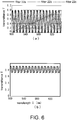
- the transmittance characteristics of the filters 22a to 22c of the filter 22 in the present example are shown in FIG. 6 .
- the filter 22a and the filter 22b both have a transmittance characteristic in which periodical changes with phases different from each other are made with respect to the change in wavelength.
- the transmittance characteristic of the other of the filter 22a or the filter 22b has a steep inclination portion, and it is possible to perform precise wavelength detection by using the transmittance characteristic of either the filter 22a or the filter 22b.
- the transmittance characteristic of the filter 22c has a characteristic of gently and linearly increasing in the wavelength range to be measured. That is, because the transmittance characteristics of the filter 22a and the filter 22b change periodically, it becomes difficult to determine on which number of cycle of the inclination portion is the transmittance based. At this time, by measuring the transmittance in combination with the transmittance of the filter 22c, it is possible to determine whether the transmittance is measured based on which number of cycle of the inclination portion.
- the transmittance characteristics having periodic and steep inclination portions are adopted in two filters, it is possible to distribute a larger number of inclination portions in the wavelength range to be measured, and it is possible to improve the wavelength detection precision.
- a phase difference is arranged in the periodic transmittance characteristics of the two filters, and in the wavelength range where the transmittance characteristic of one filter has a small or flat inclination at the peak or the bottom, the transmittance characteristic of the other filter has an inclination portion.
- a filter that has a transmittance characteristic that monotonously decreases or monotonically increases gently in the wavelength range to be measured it is possible to determine whether the transmittance is measured based on which cycle of the inclination portion. According to the above, it is possible to detect the wavelength in a wider wavelength range with higher precision.
- FIG. 6 shows a simulation result of actual transmittance characteristics of the filter 22a and the filter 22b.
- the filter can be realized by using an etalon or the like constructed according to the principle of Fabry-Perot interferometer.
- the half width at the peak portion of the transmittance characteristic of the filter in the present example is larger than the half width of the wavelength distribution of the light source, as shown in FIG. 7 . Otherwise, the wavelength distribution of the light source is applied to an adjacent cycle in the transmittance characteristic of the filter, and it is difficult to perform accurate measurement. By satisfying the condition, it becomes possible to perform more precise wavelength measurement even if the light source has a certain wavelength distribution.
- the transmittance characteristic that periodically changes in the present example may be a sinusoidal change, a trapezoidal change or a triangular wave change. Even in a case that the triangular wave change is adopted as the transmittance characteristic, a sharp change may not always be achieved at the top or the bottom, and thus phases of periodic changes in transmittance characteristics of two filters should be different. Further, in the present example, the waveform or the cycle of the transmittance characteristics of the two filters may be changed.
- Example 4 of the present invention is described.
- the hardware configuration is also the same as that of the wavelength detection device 20 described in Example 1.
- an example is described in which the four-division filter 22 is used and the entering of the incident light is made non-uniform with respect to the four filters 22a to 22d.
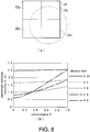
- ⁇ is a light amount division ratio which is a ratio between the light amount applied to the filter 22a and the light amount applied to the transparent plate 22d (light amount applied to filter 22a/ light amount applied to transparent plate 22d) when the incident position of light on the four-division filter 22 is shifted in the direction of the transparent plate 22d or in the opposite direction (direction of the filter 22a) as shown in (a) of FIG. 8 .
- dT/d ⁇ represents the inclination in the transmittance characteristic of the filter
- T represents the transmittance
- SN represents the SN ratio of the received signal at the light receiving element 23d that receives the light transmitted through the transparent plate 22d.
- FIG. 8 is a diagram showing the relationship between the transmittance and the wavelength detection precision with the light amount division ratio ⁇ as a parameter.
- the horizontal axis represents the transmittance T and the vertical axis represents the wavelength detection precision ⁇
- the wavelength detection precision ⁇ is a numerical value that is higher in precision as the numerical value decreases.
- the physical quantity related to the transmittance is the transmittance and the light that has passed through the filters 12a, 12b, 22a to 22d is received by the light receiving elements.
- the light that has been reflected in the filters 12a, 12b, 22a to 22d may be received by the light receiving elements, and the physical quantity related to the transmittance may be detected from the intensity of the reflected light.
- the physical quantity related to the transmittance may be reflectance, or the transmittance may be obtained by subtracting the reflectance from 1 or the like.
- the wavelength detection device wherein the physical quantity related to the transmittance is transmittance, and wherein in the transmittance characteristic for each of the plurality of optical filters (12a, 12b), the transmittance of each of the optical filters (12a, 12b) changes between approximately 0 and approximately 1 in the inclination portion.
- the wavelength detection device wherein the physical quantity related to the transmittance is transmittance, and wherein the absolute value of at least one inclination of the inclination portion is 0.0033 (1/nm) or more.
- the wavelength detection device according to any one of claims 1 to 3, wherein the inclination portion in the transmittance characteristic of each of the plurality of optical filters (12a, 12b) is arranged so as to cover the wavelength range to be measured without any gap.
- the wavelength detection device according to any one of claims 1 to 4, wherein among the transmittance characteristics of each of the plurality of optical filters (12a, 12b), two or more of the transmittance characteristics consist of curves that periodically change in the wavelength range to be measured and the curves related to each of the transmittance characteristics have different phases.
- each of the plurality of optical filters (12a, 12b) further include a transmittance characteristic consisting of a straight line or a curve that monotonically increases or monotonically decreases in the wavelength range to be measured.
- the wavelength detection device according to any one of claims 1 to 6, wherein the plurality of optical filters are configured by dividing one filter plate (22) into a plurality of regions (22a to 22d) having different transmittance characteristics, and at least one of the plurality of regions (22a to 22d) having different transmittance characteristics is formed of a transparent plate (22d).
- the wavelength detection device wherein the plurality of light receiving elements (23a to 23d) are arranged on the same substrate (23) so as to be able to respectively receive the light transmitted through the plurality of regions.
- the wavelength detection device wherein the intensity of the light entering the plurality of optical filters (23 a to 23c) and the transparent plate (22d) is non-uniform.
- a confocal measurement device including:
Landscapes
- Physics & Mathematics (AREA)
- Spectroscopy & Molecular Physics (AREA)
- General Physics & Mathematics (AREA)
- Length Measuring Devices By Optical Means (AREA)
- Spectrometry And Color Measurement (AREA)
- Investigating Or Analysing Materials By Optical Means (AREA)
- Measurement Of Optical Distance (AREA)
- Microscoopes, Condenser (AREA)
Applications Claiming Priority (2)
| Application Number | Priority Date | Filing Date | Title |
|---|---|---|---|
| JP2018044588A JP6919603B2 (ja) | 2018-03-12 | 2018-03-12 | 波長検出装置及び共焦点計測装置 |
| PCT/JP2019/010010 WO2019176938A1 (fr) | 2018-03-12 | 2019-03-12 | Dispositif de détection de longueur d'onde et dispositif de mesure confocal |
Publications (2)
| Publication Number | Publication Date |
|---|---|
| EP3767258A1 true EP3767258A1 (fr) | 2021-01-20 |
| EP3767258A4 EP3767258A4 (fr) | 2021-12-01 |
Family
ID=67906808
Family Applications (1)
| Application Number | Title | Priority Date | Filing Date |
|---|---|---|---|
| EP19766776.9A Pending EP3767258A4 (fr) | 2018-03-12 | 2019-03-12 | Dispositif de détection de longueur d'onde et dispositif de mesure confocal |
Country Status (5)
| Country | Link |
|---|---|
| US (1) | US11262238B2 (fr) |
| EP (1) | EP3767258A4 (fr) |
| JP (1) | JP6919603B2 (fr) |
| CN (1) | CN111684244B (fr) |
| WO (1) | WO2019176938A1 (fr) |
Families Citing this family (3)
| Publication number | Priority date | Publication date | Assignee | Title |
|---|---|---|---|---|
| FR3104254B1 (fr) * | 2019-12-04 | 2021-12-03 | Safran | Spectromètre optique et procédé de caractérisation d’une source associé |
| US11460347B2 (en) * | 2020-02-24 | 2022-10-04 | Lumentum Operations Llc | Optical frequency measurement device |
| DE102023120240B4 (de) | 2023-07-31 | 2025-08-07 | Jenoptik Optical Systems Gmbh | Aufnahmevorrichtung zum Erzeugen einer 3D-Aufnahme eines dreidimensionalen Objekts und Verfahren |
Family Cites Families (17)
| Publication number | Priority date | Publication date | Assignee | Title |
|---|---|---|---|---|
| US3748035A (en) * | 1971-12-28 | 1973-07-24 | Xerox Corp | Method for sequential illumination in a polychrome process |
| JPH0658817A (ja) | 1992-08-12 | 1994-03-04 | Yokogawa Electric Corp | 光波長計 |
| SE514188C2 (sv) * | 1999-02-17 | 2001-01-22 | Altitun Ab | Metod för karakterisering av en avstämbar laser och bestämmande av aktuell våglängd |
| WO2002075877A2 (fr) * | 2001-03-15 | 2002-09-26 | Digital Optics Corporation | Verrou de longueurs d'onde integre pour plus d'une longueur d'onde et procede associe |
| JP2002071459A (ja) * | 2000-08-25 | 2002-03-08 | Ntt Electornics Corp | 光波長モニタ装置 |
| JP2006086955A (ja) * | 2004-09-17 | 2006-03-30 | Fujitsu Ltd | 伝送特性評価システムおよびその擬似伝送路装置 |
| GB2399875B (en) * | 2003-03-24 | 2006-02-22 | Tsunami Photonics Ltd | Optical wavelength meter |
| US7459713B2 (en) * | 2003-08-14 | 2008-12-02 | Microptix Technologies, Llc | Integrated sensing system approach for handheld spectral measurements having a disposable sample handling apparatus |
| KR20090040343A (ko) * | 2006-07-18 | 2009-04-23 | 티아이알 테크놀로지 엘피 | 광의 세기 및 피크 파장을 결정하는 방법 및 장치 |
| US20080137061A1 (en) * | 2006-12-07 | 2008-06-12 | Christopher John Rush | Displacement Measurement Sensor Using the Confocal Principle |
| US8432553B2 (en) * | 2009-10-08 | 2013-04-30 | Massachusetts Institute Of Technology | Phase from defocused color images |
| WO2011121896A1 (fr) * | 2010-03-31 | 2011-10-06 | コニカミノルタセンシング株式会社 | Système optique pour la mesure, et dispositif de mesure de luminance de couleur et colorimètre l'utilisant |
| JP5790178B2 (ja) | 2011-03-14 | 2015-10-07 | オムロン株式会社 | 共焦点計測装置 |
| US8878114B2 (en) * | 2012-08-16 | 2014-11-04 | Nanohmics, Inc. | Apparatus and methods for locating source of and analyzing electromagnetic radiation |
| JP6347070B2 (ja) * | 2014-06-03 | 2018-06-27 | コニカミノルタ株式会社 | 分光分析装置 |
| US11019316B1 (en) * | 2018-02-09 | 2021-05-25 | Tdone, Llc | Sequential spectral imaging |
| DE102018114860A1 (de) * | 2018-06-20 | 2019-12-24 | Precitec Optronik Gmbh | Vorrichtung und Verfahren zur optischen Vermessung eines Messobjekts |
-
2018
- 2018-03-12 JP JP2018044588A patent/JP6919603B2/ja active Active
-
2019
- 2019-03-12 US US16/970,377 patent/US11262238B2/en active Active
- 2019-03-12 WO PCT/JP2019/010010 patent/WO2019176938A1/fr not_active Ceased
- 2019-03-12 EP EP19766776.9A patent/EP3767258A4/fr active Pending
- 2019-03-12 CN CN201980011576.9A patent/CN111684244B/zh active Active
Also Published As
| Publication number | Publication date |
|---|---|
| EP3767258A4 (fr) | 2021-12-01 |
| JP2019158527A (ja) | 2019-09-19 |
| US20210088383A1 (en) | 2021-03-25 |
| WO2019176938A1 (fr) | 2019-09-19 |
| CN111684244B (zh) | 2023-07-28 |
| JP6919603B2 (ja) | 2021-08-18 |
| US11262238B2 (en) | 2022-03-01 |
| CN111684244A (zh) | 2020-09-18 |
Similar Documents
| Publication | Publication Date | Title |
|---|---|---|
| US10466357B1 (en) | Optical measuring device | |
| US10228551B1 (en) | Device and method for optically measuring a measurement object | |
| US8520218B2 (en) | Measuring method of refractive index and measuring apparatus of refractive index | |
| US4891510A (en) | Device and method for determining displacement | |
| US8432553B2 (en) | Phase from defocused color images | |
| JP7410853B2 (ja) | 表面に対する間隔又は2つの表面の間の間隔を非接触で測定する方法と装置 | |
| CA2272033A1 (fr) | Disposition pour determiner les fluctuations de contraintes sur une fibre optique et sa temperature | |
| EP3767258A1 (fr) | Dispositif de détection de longueur d'onde et dispositif de mesure confocal | |
| KR20190038994A (ko) | 공초점 계측 장치 | |
| CN103267482A (zh) | 一种高精度位移检测装置及方法 | |
| JP2011237272A (ja) | 光距離計及び距離測定方法 | |
| US20170315053A1 (en) | Refractive index measurement method, refractive index measurement apparatus, and optical element manufacturing method | |
| CN102778202A (zh) | 一种膜厚测量装置及方法 | |
| US5483344A (en) | Process and apparatus for performing differential refractive index measurements using interference of modulated light beams passing through reference and test samples | |
| EP2871451A1 (fr) | Procédé de réglage d'un dispositif d'imagerie spectroscopique et système d'imagerie spectroscopique | |
| EP2792996A1 (fr) | Dispositif de détection de distance interférométrique et procédé | |
| JP2000111472A (ja) | 複屈折測定装置及びフィルムの配向測定装置 | |
| JP2013024720A (ja) | 屈折率測定方法、屈折率測定装置および屈折率測定プログラム | |
| WO2017104661A1 (fr) | Spectroscope, dispositif d'inspection optique, et dispositif de tomographie par cohérence optique (oct) | |
| JP7812916B2 (ja) | 光学的厚さ測定装置 | |
| JP2014202645A (ja) | 計測装置 | |
| JP2679810B2 (ja) | 光波長測定装置 | |
| SU366760A1 (ru) | Рефрактометр | |
| JP2005148027A (ja) | 屈折率測定装置および濃度測定装置 | |
| KR940011274B1 (ko) | 레이저 다이오드의 파장변화 측정장치 |
Legal Events
| Date | Code | Title | Description |
|---|---|---|---|
| STAA | Information on the status of an ep patent application or granted ep patent |
Free format text: STATUS: THE INTERNATIONAL PUBLICATION HAS BEEN MADE |
|
| PUAI | Public reference made under article 153(3) epc to a published international application that has entered the european phase |
Free format text: ORIGINAL CODE: 0009012 |
|
| STAA | Information on the status of an ep patent application or granted ep patent |
Free format text: STATUS: REQUEST FOR EXAMINATION WAS MADE |
|
| 17P | Request for examination filed |
Effective date: 20200914 |
|
| AK | Designated contracting states |
Kind code of ref document: A1 Designated state(s): AL AT BE BG CH CY CZ DE DK EE ES FI FR GB GR HR HU IE IS IT LI LT LU LV MC MK MT NL NO PL PT RO RS SE SI SK SM TR |
|
| AX | Request for extension of the european patent |
Extension state: BA ME |
|
| DAV | Request for validation of the european patent (deleted) | ||
| DAX | Request for extension of the european patent (deleted) | ||
| A4 | Supplementary search report drawn up and despatched |
Effective date: 20211029 |
|
| RIC1 | Information provided on ipc code assigned before grant |
Ipc: G01J 9/02 20060101ALI20211025BHEP Ipc: G01J 9/00 20060101ALI20211025BHEP Ipc: G01J 3/26 20060101ALI20211025BHEP Ipc: G01B 11/00 20060101ALI20211025BHEP Ipc: G01J 3/51 20060101AFI20211025BHEP |
|
| STAA | Information on the status of an ep patent application or granted ep patent |
Free format text: STATUS: EXAMINATION IS IN PROGRESS |
|
| 17Q | First examination report despatched |
Effective date: 20230830 |