EP3767285B1 - Capteur de composé - Google Patents
Capteur de composé Download PDFInfo
- Publication number
- EP3767285B1 EP3767285B1 EP19831012.0A EP19831012A EP3767285B1 EP 3767285 B1 EP3767285 B1 EP 3767285B1 EP 19831012 A EP19831012 A EP 19831012A EP 3767285 B1 EP3767285 B1 EP 3767285B1
- Authority
- EP
- European Patent Office
- Prior art keywords
- sensor
- terminal
- humidity
- sensitive member
- moisture
- Prior art date
- Legal status (The legal status is an assumption and is not a legal conclusion. Google has not performed a legal analysis and makes no representation as to the accuracy of the status listed.)
- Active
Links
Images







Classifications
-
- G—PHYSICS
- G01—MEASURING; TESTING
- G01K—MEASURING TEMPERATURE; MEASURING QUANTITY OF HEAT; THERMALLY-SENSITIVE ELEMENTS NOT OTHERWISE PROVIDED FOR
- G01K7/00—Measuring temperature based on the use of electric or magnetic elements directly sensitive to heat ; Power supply therefor, e.g. using thermoelectric elements
-
- G—PHYSICS
- G01—MEASURING; TESTING
- G01N—INVESTIGATING OR ANALYSING MATERIALS BY DETERMINING THEIR CHEMICAL OR PHYSICAL PROPERTIES
- G01N27/00—Investigating or analysing materials by the use of electric, electrochemical, or magnetic means
- G01N27/02—Investigating or analysing materials by the use of electric, electrochemical, or magnetic means by investigating impedance
- G01N27/22—Investigating or analysing materials by the use of electric, electrochemical, or magnetic means by investigating impedance by investigating capacitance
- G01N27/223—Investigating or analysing materials by the use of electric, electrochemical, or magnetic means by investigating impedance by investigating capacitance for determining moisture content, e.g. humidity
-
- G—PHYSICS
- G01—MEASURING; TESTING
- G01K—MEASURING TEMPERATURE; MEASURING QUANTITY OF HEAT; THERMALLY-SENSITIVE ELEMENTS NOT OTHERWISE PROVIDED FOR
- G01K7/00—Measuring temperature based on the use of electric or magnetic elements directly sensitive to heat ; Power supply therefor, e.g. using thermoelectric elements
- G01K7/16—Measuring temperature based on the use of electric or magnetic elements directly sensitive to heat ; Power supply therefor, e.g. using thermoelectric elements using resistive elements
-
- G—PHYSICS
- G01—MEASURING; TESTING
- G01K—MEASURING TEMPERATURE; MEASURING QUANTITY OF HEAT; THERMALLY-SENSITIVE ELEMENTS NOT OTHERWISE PROVIDED FOR
- G01K7/00—Measuring temperature based on the use of electric or magnetic elements directly sensitive to heat ; Power supply therefor, e.g. using thermoelectric elements
- G01K7/16—Measuring temperature based on the use of electric or magnetic elements directly sensitive to heat ; Power supply therefor, e.g. using thermoelectric elements using resistive elements
- G01K7/22—Measuring temperature based on the use of electric or magnetic elements directly sensitive to heat ; Power supply therefor, e.g. using thermoelectric elements using resistive elements the element being a non-linear resistance, e.g. thermistor
-
- G—PHYSICS
- G01—MEASURING; TESTING
- G01N—INVESTIGATING OR ANALYSING MATERIALS BY DETERMINING THEIR CHEMICAL OR PHYSICAL PROPERTIES
- G01N27/00—Investigating or analysing materials by the use of electric, electrochemical, or magnetic means
- G01N27/02—Investigating or analysing materials by the use of electric, electrochemical, or magnetic means by investigating impedance
- G01N27/04—Investigating or analysing materials by the use of electric, electrochemical, or magnetic means by investigating impedance by investigating resistance
- G01N27/12—Investigating or analysing materials by the use of electric, electrochemical, or magnetic means by investigating impedance by investigating resistance of a solid body in dependence upon absorption of a fluid; of a solid body in dependence upon reaction with a fluid, for detecting components in the fluid
- G01N27/121—Investigating or analysing materials by the use of electric, electrochemical, or magnetic means by investigating impedance by investigating resistance of a solid body in dependence upon absorption of a fluid; of a solid body in dependence upon reaction with a fluid, for detecting components in the fluid for determining moisture content, e.g. humidity, of the fluid
-
- G—PHYSICS
- G01—MEASURING; TESTING
- G01N—INVESTIGATING OR ANALYSING MATERIALS BY DETERMINING THEIR CHEMICAL OR PHYSICAL PROPERTIES
- G01N27/00—Investigating or analysing materials by the use of electric, electrochemical, or magnetic means
- G01N27/02—Investigating or analysing materials by the use of electric, electrochemical, or magnetic means by investigating impedance
- G01N27/22—Investigating or analysing materials by the use of electric, electrochemical, or magnetic means by investigating impedance by investigating capacitance
- G01N27/223—Investigating or analysing materials by the use of electric, electrochemical, or magnetic means by investigating impedance by investigating capacitance for determining moisture content, e.g. humidity
- G01N27/225—Investigating or analysing materials by the use of electric, electrochemical, or magnetic means by investigating impedance by investigating capacitance for determining moisture content, e.g. humidity by using hygroscopic materials
-
- G—PHYSICS
- G01—MEASURING; TESTING
- G01N—INVESTIGATING OR ANALYSING MATERIALS BY DETERMINING THEIR CHEMICAL OR PHYSICAL PROPERTIES
- G01N27/00—Investigating or analysing materials by the use of electric, electrochemical, or magnetic means
- G01N27/02—Investigating or analysing materials by the use of electric, electrochemical, or magnetic means by investigating impedance
- G01N27/22—Investigating or analysing materials by the use of electric, electrochemical, or magnetic means by investigating impedance by investigating capacitance
- G01N27/226—Construction of measuring vessels; Electrodes therefor
Definitions
- the present invention relates to a composite sensor capable of detecting humidity and temperature.
- the resistance change-type humidity sensor material Al 2 O 3 , TiO 2 , SiO 2 , SnO 2 , ZnO, In 2 O 3 , and polymer materials (polyelectrolytes, conducting polymers, etc.), and the like are known.
- the resistance change-type humidity sensor measures a change in electric resistance when water is sucked to these materials, to measure the relative humidity in the atmosphere.
- a bridge circuit or the like is often used in the measurement.
- Patent Document 1 a change in electric resistance between two terminals of a resistor formed of a Pt layer is measured at the time of temperature measurement.
- the humidity can be measured by measuring a change in LC resonance frequency using three terminals.
- a part (coil portion) of the resistor of the Pt layer used for the temperature measurement and humidity measurement is shared, and hence the temperature and humidity cannot be measured simultaneously, which is problematic.
- Patent Document 2 Although the physical distance between the temperature sensor and the humidity sensor is closer than when the sensors are disposed separately, a physical distance still exists between the two sensors because a substrate is disposed between the temperature sensor and the humidity sensor. Thus, the humidity around the humidity sensor and the humidity around the temperature sensor are not exactly the same. In addition, the thermal capacity of the substrate is likely to cause a difference between the temperature of the atmosphere and the temperatures of the temperature and humidity sensors, particularly when there is a change in temperature.
- Patent Document 2 Japanese Patent Application Laid-Open No. Hei 7-280767
- the humidity sensor has two terminals and the temperature sensor has two terminals, forming a structure of four terminals in total, and hence a large amount of space is required for actual mounting, which is problematic.
- the present invention has been made to solve the above problems, and an object of the present invention is to provide a composite sensor that can simultaneously measure temperature and humidity and has improved accuracy.
- a composite sensor of the present invention is a composite sensor as defined by claim 1. It is a composite sensor in which a temperature sensor that includes a temperature-sensitive member having resistivity changing in accordance with temperature and a humidity sensor that includes a moisture-sensitive member having capacitance changing in accordance with humidity are integrated.
- the composite sensor is provided with: a first terminal commonly used for the temperature sensor and the humidity sensor; a second terminal disposed to be able to measure an electrical characteristic of the temperature-sensitive member with the first terminal; and a third terminal disposed to be able to measure an electrical characteristic of the moisture-sensitive member with the first terminal.
- the temperature sensor and the humidity sensor form an integral structure, wherein the temperature-sensitive member is directly laminated on the moisture-sensitive member, and the first terminal is formed on a surface along a laminating direction of the composite sensor.
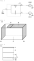
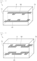
- FIG. 1 is a perspective view showing a configuration of a composite sensor of a first embodiment.
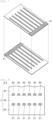
- FIG. 2 is a plan view showing an electrode forming surface of a humidity sensor unit in the composite sensor of the first embodiment.
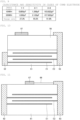
- FIG. 3 is a sectional view taken along line III-III in FIG. 1 .
- the composite sensor 1-1 has a rectangular parallelepiped shape.
- the side-surfaces of the rectangular parallelepiped include first to fourth side-surfaces FS1 to FS4, the first terminal 53 is formed on the first side-surface FS1, the third side-surface FS3 is formed on the side-surface opposite to the first side-surface FS1, and the third terminal 52 is formed on the third side-surface FS3.
- the second terminal 57 is formed on the upper surface FU orthogonal to the laminating direction of the composite sensor.
- the capacitance change-type humidity sensor unit 51 and the temperature sensor unit 56 are integrated in a three-terminal structure with the respective ground (GND) terminals made common.
- a moisture-sensitive member 2 of the capacitance change-type humidity sensor unit 51 for example, polyimide, polyamide-imide, polyamide, cellulose acetate butyrate (CAB), polymethyl methacrylate (PMMA), vinyl crotonate, polyethylene terephthalate, or a mixture thereof can be used.
- electrodes E1, E2 shown in FIG. 2 on the surface of the moisture-sensitive member 2 as shown in FIG. 3 , a change in the capacitance of the moisture-sensitive member 2 can be measured with the terminals 52, 53 connected to the electrodes E1, E2, respectively.
- the composite sensor 1-1 having the electrodes E1, E2 as external electrodes formed on the surface of the moisture-sensitive member 2 is surface-mounted on a printed wiring board as shown in FIG. 3 , for example, it is preferable to mount the second side-surface FS2 of FIG. 1 to be on the printed-wiring-board side so that comb-shaped electrodes formed on the upper surface FU and the lower surface FL are not on the board side.
- a resistor R is the equivalent resistor of the temperature-sensitive member.
- Capacitance C is the equivalent capacitance of the moisture-sensitive member. The temperature can be measured between the terminals T1 and T2, and simultaneously, the humidity can be measured between terminals T1 and T3.
- the temperature of the humidity sensor and the humidity of the temperature sensor can be more accurately corrected in a detection circuit to which the temperature sensor and the humidity sensor are connected.
- the temperature sensor and the humidity sensor having the integral structure, it is possible to reduce the size at the time of mounting as compared to when the two sensors are prepared separately. Even when the sensors are integrated in the same manner, the three-terminal structure with the GND terminals made common is formed in the present embodiment, so that the mounting area can be reduced as compared to a four-terminal structure having no common terminal.
- polyimide varnish in which a polyamic acid is dissolved in an N-methyl-2 pyrrolidone (NMP) solvent, is used.
- NMP N-methyl-2 pyrrolidone
- the polyimide varnish is applied onto a PET film using a doctor blade having a thickness of 100 um, and the sheet is moved while being dried at a temperature of 60°C to form a polyimide precursor on the PET film.
- the thickness of the sheet at this time is about 20 um (about 15 um after firing).
- the thickness of the doctor blade may be reduced.
- a polyimide precursor sheet having a thickness of 10 ⁇ m (about 7.5 um after firing) can be formed.
- the NTC thermistor as thus prepared has a B constant of 3450 K at 25°C/50°C and a resistivity ⁇ of 2.6 kQcm at 25°C.
- an NTC thermistor with any composition can be formed by using a raw material most suitable for the raw material in the preparation of the NTC thermistor.
- NiMn 2 O 4 has been described above as an example, the NTC thermistor in the present embodiment is not limited to NiMn 2 O 4 but may be any one so long as being used as an NTC thermistor in general.
- the method of forming the thick film of the NTC thermistor is not limited to the AD method but may be any method so long as forming a film at a glass transition temperature (about 450°C) or lower of the polyimide.
- the capacitance change type has been used as the humidity sensor, but in a second embodiment, a resistance change-type humidity sensor and a temperature sensor are integrated in a three-terminal structure with which the respective GNDs made common.
- a resistance change-type humidity sensor material known Al 2 O 3 , TiO 2 , SiO 2 , SnO 2 , ZnO, In 2 O 3 , polymer materials (polyelectrolytes, conducting polymers, etc.), and the like can be used.
- FIG. 6 is a sectional view showing a case where the electrodes are covered with the moisture-sensitive member.
- a sensor element (3-1) shown in FIG. 6 has a structure in which layers of polyimide having a thickness of 15 um are laminated on the surfaces of the electrodes E1, E2 of the sensor element (1-1) shown in FIG. 3 .
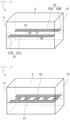
- the humidity sensor unit may employ the internal electrode structure shown in each of FIGS. 12 to 14 as is generally known for the multilayer ceramic capacitor.
- the arrangement shown in FIG. 12 is the most typical electrode arrangement.
- the arrangement shown in FIG. 13 is an electrode arrangement in which the electrodes E1, E2 are alternately laminated in the center portion.
- a counter electrode electrically connected to the terminal T2 is formed with a space from each electrode E1 on the layer where the electrode E1 electrically connected to the terminal T1 is formed
- a counter electrode electrically connected to the terminal T1 with a space from each electrode E2 is formed on the layer where the electrode E2 electrically connected to the terminal T2 is formed.
- an electrode E3 is disposed between the electrodes E1, E2.
- the capacitance can be further increased.
- the capacitance of the humidity sensor unit can be further increased.
- various internal electrode shapes may be combined. Some examples of the internal electrode shape are shown below.
- an internal electrode is provided inside a humidity sensor material, and the internal electrode is formed into a coil shape.
- the internal electrode a combination of electrode shapes such as a flat plate shape, a comb shape, and a meandering shape may be used, and a plurality of layers of these electrodes may be formed.
- the resonance circuit for humidity measurement can be resonated without using an external inductor.
- a NiCr/Monel/Ag electrode is formed by sputtering.
- the sheet is cut into a target size and then fired under an air atmosphere at 350°C for one hour. After an Ag extended electrode is formed on the fired sample, the sample is further fired at 100°C to complete preparation of a target composite sensor element.
- the inventors of the present invention experimentally confirmed that the resonance frequency of the sensor element (4-1) was 6.907 GHz.
- FIG. 22 is a view showing a state where a three-dimensional coil is formed inside the element.
- the element employing the three-dimensional coil shown in FIG. 22 is taken as a sensor element (4-3).
- the sensor element (4-3) is obtained, as in the cases of the sensor element (4-1) and the sensor element (4-2), by opening a via in the polyimide precursor sheet, pouring an Ag electrode, printing the Ag electrode, and laminating 73 sheets in total.
- the inventors of the present invention experimentally confirmed that the resonance frequency of the sensor element (4-3) prepared in this manner was 0.715 GHz.
- the resonance frequency can be significantly lowered as compared to the sensor element (4-1) and the sensor element (4-2). Therefore, the resonance frequency necessary for humidity measurement can be measured using a low-speed microcomputer having a low clock frequency.
- a composite material of a humidity sensor material and a material having a dielectric constant different from that of the humidity sensor material is used as the moisture-sensitive member of the humidity sensor unit.
- the material having a different dielectric constant has higher relative permittivity than the humidity sensor material.
- the humidity sensor material for example, polyimide, polyamide-imide, polyamide, cellulose acetate butyrate (CAB), polymethyl methacrylate (PMMA), vinyl crotonate, polyethylene terephthalate, or a mixture thereof can be used.
- a ceramic dielectric material such as BaTiOs, Pb(Zr,Ti)O 3 , (K,Na)NbO 3 , or CaCu 3 Ti 4 O 12 , can be used.
- the humidity sensor material and the dielectric material may be uniformly mixed, non-uniformly mixed, or localized.
- FIG. 24 is a diagram showing the characteristics of the sensor elements (5-1), (5-2), (5-3) side by side.
- the capacitances of the humidity sensor units of the sensor elements (5-1), (5-2), (5-3) are 6.760 pF, 13.810 pF, and 1.209 nF. It is seen therefrom that the capacitances are about 8.35 to 11.65 times larger than when the moisture-sensitive member made of only polyimide is used.
- a moisture-sensitive member using a composite material of a humidity sensor material and a material having relative magnetic permeability higher than that of the humidity sensor material is examined.
- the material having high relative magnetic permeability various ferrites (spinel ferrite, hexagonal ferrite, garnet ferrite, etc.), various ceramic magnetic materials (iron oxide, etc.), permalloy, various stainless steels, and various metal magnetic materials (FePt, PtCo, FeCo, Ni, Fe, etc.) can be used.
- the humidity sensor material and the magnetic material may be uniformly mixed, non-uniformly mixed, or localized.
- the inductance of the humidity sensor unit can be increased. This eliminates the need for an external inductor when an LC oscillation circuit is constituted using the composite sensor.
- the mixture is used as a raw material for preparing a composite sheet, and sheet formation, electrode printing, lamination, pressure bonding, and firing are performed in the same manner and under the same conditions as at the time of preparing the sensor element (1-1) of the first embodiment, to prepare a humidity sensor using the composite sheet of polyimide and the ferrite material.
- Structures formed by preparing the same structures as those of the sensor elements (4-1), (4-2), (4-3) shown in the fourth embodiment using the composite sheet of polyimide and the ferrite material, are taken as sensor elements (6-1), (6-2), (6-3).
- FIG. 26 is a diagram showing the characteristics of the sensor elements (6-1), (6-2), (6-3) side by side.
- the resonance frequencies of the sensor elements (6-1), (6-2), (6-3) are 3.677 GHz, 0.427 GHz, and 39.812 MHz, respectively. It is seen therefrom that the frequencies are about 46.76% to 94.54% lower than when a moisture-sensitive member made of only polyimide is used.
- both the capacitance and inductance of the humidity sensor unit can be increased.
- an external inductor which is used at the time of constituting the LC oscillation circuit by using the composite sensor, becomes unnecessary.
- the distribution of the proportion of the humidity sensor material may be uniform, non-uniform, or localized so long as the above requirements are satisfied.
- the concentration of the humidity sensor material on the surface part is increased as described above, the change in capacitance due to humidity can be increased, so that the sensitivity to humidity can be increased while the capacitance and inductance are kept large.
- FIG. 28 is a view for explaining the shapes of laminated coil electrodes of the humidity sensor unit in the eighth embodiment.
- the following case is taken as a sensor element (8-1): in the configuration of the sensor element (6-3) described in the sixth embodiment, of the 73 layers of laminated sheets, two layers from the surface are made of 100% polyimide, and the central 71 layers are made of a composite sheet with a mixture ratio being a volume ratio of polyimide to the ferrite material (with relative magnetic permeability ⁇ r of 1300) of 1:1.
- the electrode on the surface sandwiched by the polyimide sheets is the same comb electrode as the sensor element (1-1).
- the resonance frequency of the sensor element (8-1) is 42.193 MHz. Although this resonance frequency is slightly higher than the resonance frequency of 39.812 MHz of the sensor element (6-3), the change in resonance frequency due to the change in humidity from 10%RH to 90%RH is 23.28%. It is understood that the rate of change is higher than 20.66% for the sensor element (6-3). It is thus understood that the sensitivity to humidity can be increased as compared to the case of the sixth embodiment.
- the material composition in the center portion is the same for comparison with the sensor element (6-3), but the resonance frequency can be lowered by increasing the proportion of the ferrite material in the center portion. Further, by increasing the proportion and thickness of the polyimide on the surface, the sensitivity to humidity can be increased despite the increase in the resonance frequency of the sensor element.
- the composite sensor of the eighth embodiment is characterized in that the moisture-sensitive member of the humidity sensor unit includes the first portion and the second portion that is disposed closer to the main surface (outer surface) of the humidity sensor unit than the first portion and has a higher proportion of the humidity sensor material (polyimide, etc.) than the first portion.
- a composite sensor of a ninth embodiment is the same as the composite sensor of the eighth embodiment in that the proportion of the humidity sensor material on the element surface of the humidity sensor unit is 100%, but the composite sensor of a ninth embodiment is different in that the proportion of the humidity sensor material inside the element is 0%.
- This proportion is the most suitable example in which the change in capacitance due to the change in humidity can be increased while the capacitance and inductance are increased.
- the center part is the same as a general chip inductor structure, so that a general preparation process can be used as it is.
- the polyimide varnish was spin-coated on the laminated ferrite sheets L1 to L71 and then dried at 130°C Thereafter, a sheet L72 having a comb electrode pattern of Ag printed thereon is disposed, and the polyimide varnish is further spin-coated on the upper part of the sheet L72 and dried at 130°C. Thereafter, as in the first embodiment, the NTC thermistor of NiMn 2 O 4 and the electrode are formed on the L1 side of the laminated sheet by the AD method.
- a polyimide precursor/Ag electrode/polyimide precursor/laminated ferrite sheets/NTC thermistor structure can be formed. In this state, firing is performed at 350°C for one hour in an air atmosphere and then cut into a target size, whereby the sensor element (9-1) can be prepared.
- FIG. 29 is a diagram showing the characteristics of the sensor elements (6-3), (8-1), (9-1) side by side.
- the resonance frequency of the sensor element (9-1) is 9.560 MHz, and it is seen that the resonance frequency is lower than the resonance frequency of the sensor element (8-1).
- the rate of change in resonance frequency due to the humidity change from 10%RH to 90%RH was 10.85%. This is a very large change in frequency of about 1.1 MHz, although the rate of change is lower than that of the sensor element (8-1). Therefore, by adopting the structure of the sensor element (9-1), a sufficiently large change in frequency can be obtained while the resonance frequency is lowered significantly.
- the composite sensor of each of the first to ninth embodiments separate voltages can be applied to the temperature sensor unit by using the first terminal and the second terminal, and to the humidity sensor unit by using the first terminal and the third terminal, so that it is possible to simultaneously measure temperature and humidity.
- the temperature sensor and the humidity sensor having the integral structure the temperature of the humidity sensor and the humidity of the temperature sensor can be corrected more accurately.
- the size can be reduced at the time of mounting as compared to when the temperature sensor and the humidity sensor are provided separately.
- the mounting area can be reduced as compared to a composite sensor having a four-terminal structure.
Landscapes
- Chemical & Material Sciences (AREA)
- Physics & Mathematics (AREA)
- General Physics & Mathematics (AREA)
- Electrochemistry (AREA)
- Health & Medical Sciences (AREA)
- Life Sciences & Earth Sciences (AREA)
- Analytical Chemistry (AREA)
- Biochemistry (AREA)
- General Health & Medical Sciences (AREA)
- Chemical Kinetics & Catalysis (AREA)
- Immunology (AREA)
- Pathology (AREA)
- Nonlinear Science (AREA)
- Investigating Or Analyzing Materials By The Use Of Electric Means (AREA)
- Investigating Or Analyzing Materials By The Use Of Fluid Adsorption Or Reactions (AREA)
Claims (9)
- Capteur composite comprenant un capteur de température (56, 66) qui comporte un élément sensible à la température présentant une résistivité qui varie selon la température, et un capteur d'humidité (51, 61) qui comporte un élément sensible à l'humidité présentant une capacité ou une résistivité qui varie selon l'humidité, le capteur composite comprenant en outre :une première borne (53, 63) utilisée en commun pour le capteur de température (56, 66) et pour le capteur d'humidité (51, 61) ;une deuxième borne (57, 67) disposée de façon à pouvoir mesurer une caractéristique électrique de l'élément sensible à la température conjointement avec la première borne (53, 63) ; etune troisième borne (52, 62) disposée de façon à pouvoir mesurer une caractéristique électrique de l'élément sensible à l'humidité conjointement avec la première borne (53, 63),dans lequel le capteur de température (56, 66) et le capteur d'humidité (51, 61) forment une structure en une seule pièce,dans lequel l'élément sensible à la température est stratifié directement sur l'élément sensible à l'humidité,caractérisé en ce que la première borne (53, 63) est formée sur une surface (FS1) le long d'une direction de stratification du capteur composite.
- Le capteur composite de la revendication 1, dans lequelle capteur composite présente une forme de parallélépipède rectangulaire,le parallélépipède rectangulaire comporte des surfaces première à quatrième (FS1, FS2, FS3, FS4) le long de ladite direction de stratification du capteur composite,la première borne (53, 63) est formée sur la première surface (FS1),la troisième surface (FS3) est une surface opposée à la première surface (FS1), etla troisième borne (52, 62) est formée sur la troisième surface (FS3).
- Le capteur composite selon les revendications 1 ou 2, dans lequel la deuxième borne (57, 67) est formée sur une surface (FU) orthogonale à la direction de stratification.
- Le capteur composite selon l'une quelconque des revendications 1 à 3, dans lequella première borne (53, 63) est une borne de terre,une source de tension à courant continu (CC) est connectée entre la première borne (53, 63) et la deuxième borne (57, 67), etune source de tension à courant alternatif (CA) est connectée entre la première borne (53, 63) et la troisième borne (52, 62).
- Le capteur composite selon la revendication 1, comprenant en outre :une première électrode connectée électriquement à la première borne (53, 63) ; etune seconde électrode connectée électriquement à la troisième borne (52, 62),dans lequella première électrode comprend une première unité électrode interne comportant une première surface principale recouverte de l'élément sensible à l'humidité, et une deuxième surface principale recouverte de l'élément sensible à l'humidité,la seconde électrode comprend une seconde unité électrode interne comportant une troisième surface principale recouverte de l'élément sensible à l'humidité, et une quatrième surface principale recouverte de l'élément sensible à l'humidité, etla première unité électrode interne et la seconde unité électrode interne sont disposées en travers de l'élément sensible à l'humidité.
- Le capteur composite selon la revendication 1, dans lequel l'élément sensible à l'humidité est formé à partir d'un matériau composite qui comporte un premier matériau présentant une capacité qui varie selon une variation de l'humidité, et un deuxième matériau présentant une constante diélectrique différente d'une constante diélectrique du premier matériau.
- Le capteur composite selon la revendication 1, dans lequel l'élément sensible à l'humidité est formé à partir d'un matériau composite qui comporte un premier matériau présentant une capacité qui varie selon une variation de l'humidité, et un deuxième matériau qui est une substance magnétique.
- Le capteur composite selon la revendication 1, dans lequel l'élément sensible à l'humidité est formé à partir d'un matériau composite qui comporte un premier matériau présentant une capacité qui varie selon une variation de l'humidité, un deuxième matériau présentant une constante diélectrique différente d'une constante diélectrique du premier matériau, et un troisième matériau qui est une substance magnétique.
- Le capteur composite selon l'une quelconque des revendications 6 à 8, dans lequel l'élément sensible à l'humidité comprend une première partie et une seconde partie qui est disposée plus près d'une surface principale de l'élément sensible à l'humidité que la première partie, et qui contient une proportion du premier matériau supérieure à celle de la première partie.
Applications Claiming Priority (2)
| Application Number | Priority Date | Filing Date | Title |
|---|---|---|---|
| JP2018127525 | 2018-07-04 | ||
| PCT/JP2019/026518 WO2020009164A1 (fr) | 2018-07-04 | 2019-07-03 | Capteur de composé |
Publications (3)
| Publication Number | Publication Date |
|---|---|
| EP3767285A1 EP3767285A1 (fr) | 2021-01-20 |
| EP3767285A4 EP3767285A4 (fr) | 2021-12-01 |
| EP3767285B1 true EP3767285B1 (fr) | 2025-01-08 |
Family
ID=69060847
Family Applications (1)
| Application Number | Title | Priority Date | Filing Date |
|---|---|---|---|
| EP19831012.0A Active EP3767285B1 (fr) | 2018-07-04 | 2019-07-03 | Capteur de composé |
Country Status (5)
| Country | Link |
|---|---|
| US (1) | US11346801B2 (fr) |
| EP (1) | EP3767285B1 (fr) |
| JP (2) | JP6965995B2 (fr) |
| CN (1) | CN112313507B (fr) |
| WO (1) | WO2020009164A1 (fr) |
Families Citing this family (3)
| Publication number | Priority date | Publication date | Assignee | Title |
|---|---|---|---|---|
| WO2020008935A1 (fr) * | 2018-07-04 | 2020-01-09 | 株式会社村田製作所 | Capteur d'humidité et étiquette rfid le comprenant |
| CN114858339B (zh) * | 2022-04-08 | 2023-01-03 | 武汉大学 | 一种柔性阵列式湿度压力传感器及其制备工艺 |
| US12228538B2 (en) * | 2023-03-24 | 2025-02-18 | Qualcomm Incorporated | Moisture sensor having integrated heating element |
Citations (1)
| Publication number | Priority date | Publication date | Assignee | Title |
|---|---|---|---|---|
| JPH01276057A (ja) * | 1988-04-28 | 1989-11-06 | Matsushita Electric Ind Co Ltd | 湿度センサ |
Family Cites Families (30)
| Publication number | Priority date | Publication date | Assignee | Title |
|---|---|---|---|---|
| US4017820A (en) * | 1975-07-25 | 1977-04-12 | Illinois Tool Works Inc. | Humidity sensor with multiple electrode layers separated by a porous monolithic ceramic dielectric structure |
| JPS54102147A (en) * | 1978-01-30 | 1979-08-11 | Matsushita Electric Ind Co Ltd | Temperature and humidity sensor |
| JPS54102148A (en) * | 1978-01-30 | 1979-08-11 | Matsushita Electric Ind Co Ltd | Temperature and humidity sensor |
| JPS54107797A (en) * | 1978-02-13 | 1979-08-23 | Denki Onkyo Co Ltd | Humidityysensitive element employing highhmolecular electrolyte |
| JPS5991355A (ja) | 1982-11-16 | 1984-05-26 | Murata Mfg Co Ltd | 湿度センサ |
| JPS62156551A (ja) * | 1985-12-28 | 1987-07-11 | Sharp Corp | 温度/湿度センサ |
| JP3002276B2 (ja) * | 1991-01-31 | 2000-01-24 | 株式会社鷺宮製作所 | 湿度センサ |
| JPH04289448A (ja) * | 1991-03-18 | 1992-10-14 | Nippon Parkerizing Co Ltd | 温湿度センサ及びこの温湿度センサによる温度・湿度の測定方法 |
| JP3067010B2 (ja) * | 1994-02-09 | 2000-07-17 | ティーディーケイ株式会社 | 絶対湿度センサ |
| JPH07280767A (ja) | 1994-04-08 | 1995-10-27 | Nippon Soken Inc | 湿度センサおよび湿度測定方法 |
| JPH0882612A (ja) * | 1994-09-14 | 1996-03-26 | Oki Electric Ind Co Ltd | 電気容量式湿度センサ |
| JPH11101765A (ja) * | 1997-07-28 | 1999-04-13 | Matsushita Electric Ind Co Ltd | 湿度センサ |
| US6222376B1 (en) * | 1999-01-16 | 2001-04-24 | Honeywell International Inc. | Capacitive moisture detector and method of making the same |
| US7106167B2 (en) * | 2002-06-28 | 2006-09-12 | Heetronix | Stable high temperature sensor system with tungsten on AlN |
| JP4229885B2 (ja) * | 2004-08-18 | 2009-02-25 | 株式会社デンソー | 容量式物理量検出装置 |
| JP4473070B2 (ja) * | 2004-08-20 | 2010-06-02 | 株式会社デンソー | 電極保護構造を有するセンサの製造方法 |
| JP2006225454A (ja) | 2005-02-16 | 2006-08-31 | Toyobo Co Ltd | ポリイミド系樹脂 |
| DE102006031344A1 (de) * | 2006-07-06 | 2008-01-10 | Epcos Ag | Elektrisches Bauelement mit einem Sensorelement, Verfahren zur Verkapselung eines Sensorelements und Verfahren zur Herstellung einer Plattenanordnung |
| US20090288484A1 (en) * | 2008-05-21 | 2009-11-26 | Honeywell International Inc. | Integrated mechanical package design for combi sensor apparatus |
| GB0814452D0 (en) * | 2008-08-07 | 2008-09-10 | Melexis Nv | Laminated temperature sensor |
| KR101093612B1 (ko) * | 2008-11-12 | 2011-12-15 | 전자부품연구원 | 정전용량형 습도센서 및 그 제조방법 |
| DE102009026439A1 (de) * | 2009-05-25 | 2010-12-09 | Innovative Sensor Technology Ist Ag | Sensorelement und Verfahren zur Herstellung eines solchen |
| US20100307238A1 (en) * | 2009-06-05 | 2010-12-09 | The Governors Of The University Of Alberta | Humidity sensor and method of manufacturing the same |
| WO2012141105A1 (fr) * | 2011-04-15 | 2012-10-18 | 株式会社村田製作所 | Elément de film mince piézoélectrique |
| JP2013134078A (ja) * | 2011-12-26 | 2013-07-08 | Denso Corp | 容量式物理量検出装置 |
| JP6032140B2 (ja) * | 2013-06-26 | 2016-11-24 | 株式会社デンソー | 流量測定装置 |
| JP6098724B2 (ja) * | 2013-08-13 | 2017-03-22 | 株式会社村田製作所 | 温湿度センサ |
| CN103616087B (zh) * | 2013-10-28 | 2016-02-17 | 天津科技大学 | 一种冷藏运输载具用温湿度传感器及其制备方法 |
| JP2018059780A (ja) | 2016-10-04 | 2018-04-12 | 株式会社デンソー | 半導体湿度センサの製造方法 |
| EP3646016B1 (fr) * | 2017-06-28 | 2025-01-15 | E+E Elektronik Ges.m.b.H. | Dispositif capteur pour la mesure capacitive de l'humidité |
-
2019
- 2019-07-03 JP JP2020529036A patent/JP6965995B2/ja active Active
- 2019-07-03 WO PCT/JP2019/026518 patent/WO2020009164A1/fr not_active Ceased
- 2019-07-03 CN CN201980041377.2A patent/CN112313507B/zh active Active
- 2019-07-03 EP EP19831012.0A patent/EP3767285B1/fr active Active
-
2020
- 2020-12-17 US US17/125,482 patent/US11346801B2/en active Active
-
2021
- 2021-10-20 JP JP2021171642A patent/JP7164003B2/ja active Active
Patent Citations (1)
| Publication number | Priority date | Publication date | Assignee | Title |
|---|---|---|---|---|
| JPH01276057A (ja) * | 1988-04-28 | 1989-11-06 | Matsushita Electric Ind Co Ltd | 湿度センサ |
Also Published As
| Publication number | Publication date |
|---|---|
| JP6965995B2 (ja) | 2021-11-10 |
| CN112313507B (zh) | 2024-08-06 |
| JP2022023151A (ja) | 2022-02-07 |
| US11346801B2 (en) | 2022-05-31 |
| EP3767285A1 (fr) | 2021-01-20 |
| JPWO2020009164A1 (ja) | 2021-04-01 |
| JP7164003B2 (ja) | 2022-11-01 |
| US20210190716A1 (en) | 2021-06-24 |
| WO2020009164A1 (fr) | 2020-01-09 |
| EP3767285A4 (fr) | 2021-12-01 |
| CN112313507A (zh) | 2021-02-02 |
Similar Documents
| Publication | Publication Date | Title |
|---|---|---|
| US11913896B2 (en) | Humidity sensor and RFID tag including the same | |
| US11346801B2 (en) | Composite sensor | |
| EP1387164B1 (fr) | Capteur de détection de type capacitif | |
| US6781388B2 (en) | Liquid property sensor | |
| US5410291A (en) | Thermistor type temperature sensor | |
| US11231354B2 (en) | Method of manufacturing particulate matter detection element | |
| US6463789B2 (en) | Gas sensor | |
| JP5425225B2 (ja) | 非導電性の二酸化ジルコニウム | |
| US20110139618A1 (en) | Ceramic exhaust gas sensor | |
| US4883366A (en) | Temperature sensor | |
| US20090315569A1 (en) | Impedance measuring instrument and impedance measuring method for fine particle collector | |
| JP3029482B2 (ja) | 静電容量型センサの製造方法 | |
| JP2014222812A (ja) | 発振デバイス | |
| JP2008223495A (ja) | 温度測定ハニカム構造体 | |
| JP7670270B2 (ja) | 抵抗型酸素ガスセンサ及び酸素センサ装置 | |
| EP3460430B1 (fr) | Capteur de température et dispositif de mesure de température | |
| CN113557578B (zh) | 电气元件 | |
| JPS60194342A (ja) | 感湿素子及びその使用方法 | |
| JPH09148109A (ja) | 複合機能電子部品 | |
| JPH01196558A (ja) | 湿度センサ | |
| JPH04238260A (ja) | 感湿素子 | |
| JPH0536562A (ja) | セラミツク積層コンデンサ | |
| JPH02264854A (ja) | 温湿度センサ | |
| JPH0653010A (ja) | 積層型サ−ミスタ | |
| JPH11101765A (ja) | 湿度センサ |
Legal Events
| Date | Code | Title | Description |
|---|---|---|---|
| STAA | Information on the status of an ep patent application or granted ep patent |
Free format text: STATUS: THE INTERNATIONAL PUBLICATION HAS BEEN MADE |
|
| PUAI | Public reference made under article 153(3) epc to a published international application that has entered the european phase |
Free format text: ORIGINAL CODE: 0009012 |
|
| STAA | Information on the status of an ep patent application or granted ep patent |
Free format text: STATUS: REQUEST FOR EXAMINATION WAS MADE |
|
| 17P | Request for examination filed |
Effective date: 20201012 |
|
| AK | Designated contracting states |
Kind code of ref document: A1 Designated state(s): AL AT BE BG CH CY CZ DE DK EE ES FI FR GB GR HR HU IE IS IT LI LT LU LV MC MK MT NL NO PL PT RO RS SE SI SK SM TR |
|
| AX | Request for extension of the european patent |
Extension state: BA ME |
|
| DAV | Request for validation of the european patent (deleted) | ||
| DAX | Request for extension of the european patent (deleted) | ||
| A4 | Supplementary search report drawn up and despatched |
Effective date: 20211028 |
|
| RIC1 | Information provided on ipc code assigned before grant |
Ipc: G01N 25/56 20060101ALI20211022BHEP Ipc: G01N 27/12 20060101ALI20211022BHEP Ipc: G01N 27/04 20060101ALI20211022BHEP Ipc: G01K 7/16 20060101ALI20211022BHEP Ipc: G01N 27/22 20060101AFI20211022BHEP |
|
| STAA | Information on the status of an ep patent application or granted ep patent |
Free format text: STATUS: EXAMINATION IS IN PROGRESS |
|
| 17Q | First examination report despatched |
Effective date: 20220713 |
|
| GRAP | Despatch of communication of intention to grant a patent |
Free format text: ORIGINAL CODE: EPIDOSNIGR1 |
|
| STAA | Information on the status of an ep patent application or granted ep patent |
Free format text: STATUS: GRANT OF PATENT IS INTENDED |
|
| INTG | Intention to grant announced |
Effective date: 20240829 |
|
| GRAS | Grant fee paid |
Free format text: ORIGINAL CODE: EPIDOSNIGR3 |
|
| GRAA | (expected) grant |
Free format text: ORIGINAL CODE: 0009210 |
|
| STAA | Information on the status of an ep patent application or granted ep patent |
Free format text: STATUS: THE PATENT HAS BEEN GRANTED |
|
| AK | Designated contracting states |
Kind code of ref document: B1 Designated state(s): AL AT BE BG CH CY CZ DE DK EE ES FI FR GB GR HR HU IE IS IT LI LT LU LV MC MK MT NL NO PL PT RO RS SE SI SK SM TR |
|
| REG | Reference to a national code |
Ref country code: GB Ref legal event code: FG4D |
|
| REG | Reference to a national code |
Ref country code: CH Ref legal event code: EP |
|
| REG | Reference to a national code |
Ref country code: DE Ref legal event code: R096 Ref document number: 602019064694 Country of ref document: DE |
|
| REG | Reference to a national code |
Ref country code: IE Ref legal event code: FG4D |
|
| REG | Reference to a national code |
Ref country code: LT Ref legal event code: MG9D |
|
| REG | Reference to a national code |
Ref country code: NL Ref legal event code: MP Effective date: 20250108 |
|
| REG | Reference to a national code |
Ref country code: AT Ref legal event code: MK05 Ref document number: 1758622 Country of ref document: AT Kind code of ref document: T Effective date: 20250108 |
|
| PG25 | Lapsed in a contracting state [announced via postgrant information from national office to epo] |
Ref country code: NL Free format text: LAPSE BECAUSE OF FAILURE TO SUBMIT A TRANSLATION OF THE DESCRIPTION OR TO PAY THE FEE WITHIN THE PRESCRIBED TIME-LIMIT Effective date: 20250108 |
|
| PG25 | Lapsed in a contracting state [announced via postgrant information from national office to epo] |
Ref country code: RS Free format text: LAPSE BECAUSE OF FAILURE TO SUBMIT A TRANSLATION OF THE DESCRIPTION OR TO PAY THE FEE WITHIN THE PRESCRIBED TIME-LIMIT Effective date: 20250408 |
|
| PG25 | Lapsed in a contracting state [announced via postgrant information from national office to epo] |
Ref country code: FI Free format text: LAPSE BECAUSE OF FAILURE TO SUBMIT A TRANSLATION OF THE DESCRIPTION OR TO PAY THE FEE WITHIN THE PRESCRIBED TIME-LIMIT Effective date: 20250108 |
|
| PG25 | Lapsed in a contracting state [announced via postgrant information from national office to epo] |
Ref country code: PL Free format text: LAPSE BECAUSE OF FAILURE TO SUBMIT A TRANSLATION OF THE DESCRIPTION OR TO PAY THE FEE WITHIN THE PRESCRIBED TIME-LIMIT Effective date: 20250108 |
|
| PG25 | Lapsed in a contracting state [announced via postgrant information from national office to epo] |
Ref country code: ES Free format text: LAPSE BECAUSE OF FAILURE TO SUBMIT A TRANSLATION OF THE DESCRIPTION OR TO PAY THE FEE WITHIN THE PRESCRIBED TIME-LIMIT Effective date: 20250108 |
|
| PG25 | Lapsed in a contracting state [announced via postgrant information from national office to epo] |
Ref country code: NO Free format text: LAPSE BECAUSE OF FAILURE TO SUBMIT A TRANSLATION OF THE DESCRIPTION OR TO PAY THE FEE WITHIN THE PRESCRIBED TIME-LIMIT Effective date: 20250408 Ref country code: IS Free format text: LAPSE BECAUSE OF FAILURE TO SUBMIT A TRANSLATION OF THE DESCRIPTION OR TO PAY THE FEE WITHIN THE PRESCRIBED TIME-LIMIT Effective date: 20250508 |
|
| PG25 | Lapsed in a contracting state [announced via postgrant information from national office to epo] |
Ref country code: HR Free format text: LAPSE BECAUSE OF FAILURE TO SUBMIT A TRANSLATION OF THE DESCRIPTION OR TO PAY THE FEE WITHIN THE PRESCRIBED TIME-LIMIT Effective date: 20250108 |
|
| PG25 | Lapsed in a contracting state [announced via postgrant information from national office to epo] |
Ref country code: PT Free format text: LAPSE BECAUSE OF FAILURE TO SUBMIT A TRANSLATION OF THE DESCRIPTION OR TO PAY THE FEE WITHIN THE PRESCRIBED TIME-LIMIT Effective date: 20250508 Ref country code: LV Free format text: LAPSE BECAUSE OF FAILURE TO SUBMIT A TRANSLATION OF THE DESCRIPTION OR TO PAY THE FEE WITHIN THE PRESCRIBED TIME-LIMIT Effective date: 20250108 |
|
| PG25 | Lapsed in a contracting state [announced via postgrant information from national office to epo] |
Ref country code: GR Free format text: LAPSE BECAUSE OF FAILURE TO SUBMIT A TRANSLATION OF THE DESCRIPTION OR TO PAY THE FEE WITHIN THE PRESCRIBED TIME-LIMIT Effective date: 20250409 Ref country code: BG Free format text: LAPSE BECAUSE OF FAILURE TO SUBMIT A TRANSLATION OF THE DESCRIPTION OR TO PAY THE FEE WITHIN THE PRESCRIBED TIME-LIMIT Effective date: 20250108 |
|
| PG25 | Lapsed in a contracting state [announced via postgrant information from national office to epo] |
Ref country code: AT Free format text: LAPSE BECAUSE OF FAILURE TO SUBMIT A TRANSLATION OF THE DESCRIPTION OR TO PAY THE FEE WITHIN THE PRESCRIBED TIME-LIMIT Effective date: 20250108 |
|
| PG25 | Lapsed in a contracting state [announced via postgrant information from national office to epo] |
Ref country code: SE Free format text: LAPSE BECAUSE OF FAILURE TO SUBMIT A TRANSLATION OF THE DESCRIPTION OR TO PAY THE FEE WITHIN THE PRESCRIBED TIME-LIMIT Effective date: 20250108 |
|
| PG25 | Lapsed in a contracting state [announced via postgrant information from national office to epo] |
Ref country code: SM Free format text: LAPSE BECAUSE OF FAILURE TO SUBMIT A TRANSLATION OF THE DESCRIPTION OR TO PAY THE FEE WITHIN THE PRESCRIBED TIME-LIMIT Effective date: 20250108 |
|
| REG | Reference to a national code |
Ref country code: DE Ref legal event code: R097 Ref document number: 602019064694 Country of ref document: DE |
|
| PG25 | Lapsed in a contracting state [announced via postgrant information from national office to epo] |
Ref country code: DK Free format text: LAPSE BECAUSE OF FAILURE TO SUBMIT A TRANSLATION OF THE DESCRIPTION OR TO PAY THE FEE WITHIN THE PRESCRIBED TIME-LIMIT Effective date: 20250108 |
|
| PGFP | Annual fee paid to national office [announced via postgrant information from national office to epo] |
Ref country code: DE Payment date: 20250731 Year of fee payment: 7 |
|
| PG25 | Lapsed in a contracting state [announced via postgrant information from national office to epo] |
Ref country code: CZ Free format text: LAPSE BECAUSE OF FAILURE TO SUBMIT A TRANSLATION OF THE DESCRIPTION OR TO PAY THE FEE WITHIN THE PRESCRIBED TIME-LIMIT Effective date: 20250108 Ref country code: EE Free format text: LAPSE BECAUSE OF FAILURE TO SUBMIT A TRANSLATION OF THE DESCRIPTION OR TO PAY THE FEE WITHIN THE PRESCRIBED TIME-LIMIT Effective date: 20250108 |
|
| PG25 | Lapsed in a contracting state [announced via postgrant information from national office to epo] |
Ref country code: RO Free format text: LAPSE BECAUSE OF FAILURE TO SUBMIT A TRANSLATION OF THE DESCRIPTION OR TO PAY THE FEE WITHIN THE PRESCRIBED TIME-LIMIT Effective date: 20250108 |
|
| PG25 | Lapsed in a contracting state [announced via postgrant information from national office to epo] |
Ref country code: SK Free format text: LAPSE BECAUSE OF FAILURE TO SUBMIT A TRANSLATION OF THE DESCRIPTION OR TO PAY THE FEE WITHIN THE PRESCRIBED TIME-LIMIT Effective date: 20250108 |
|
| PLBE | No opposition filed within time limit |
Free format text: ORIGINAL CODE: 0009261 |
|
| STAA | Information on the status of an ep patent application or granted ep patent |
Free format text: STATUS: NO OPPOSITION FILED WITHIN TIME LIMIT |
|
| REG | Reference to a national code |
Ref country code: CH Ref legal event code: L10 Free format text: ST27 STATUS EVENT CODE: U-0-0-L10-L00 (AS PROVIDED BY THE NATIONAL OFFICE) Effective date: 20251119 |
|
| 26N | No opposition filed |
Effective date: 20251009 |
|
| PG25 | Lapsed in a contracting state [announced via postgrant information from national office to epo] |
Ref country code: IT Free format text: LAPSE BECAUSE OF FAILURE TO SUBMIT A TRANSLATION OF THE DESCRIPTION OR TO PAY THE FEE WITHIN THE PRESCRIBED TIME-LIMIT Effective date: 20250108 |
|
| REG | Reference to a national code |
Ref country code: CH Ref legal event code: H13 Free format text: ST27 STATUS EVENT CODE: U-0-0-H10-H13 (AS PROVIDED BY THE NATIONAL OFFICE) Effective date: 20260224 |
|
| PG25 | Lapsed in a contracting state [announced via postgrant information from national office to epo] |
Ref country code: LU Free format text: LAPSE BECAUSE OF NON-PAYMENT OF DUE FEES Effective date: 20250703 |
|
| GBPC | Gb: european patent ceased through non-payment of renewal fee |
Effective date: 20250703 |
|
| REG | Reference to a national code |
Ref country code: BE Ref legal event code: MM Effective date: 20250731 |
|
| PG25 | Lapsed in a contracting state [announced via postgrant information from national office to epo] |
Ref country code: GB Free format text: LAPSE BECAUSE OF NON-PAYMENT OF DUE FEES Effective date: 20250703 |
|
| PG25 | Lapsed in a contracting state [announced via postgrant information from national office to epo] |
Ref country code: BE Free format text: LAPSE BECAUSE OF NON-PAYMENT OF DUE FEES Effective date: 20250731 |
|
| PG25 | Lapsed in a contracting state [announced via postgrant information from national office to epo] |
Ref country code: FR Free format text: LAPSE BECAUSE OF NON-PAYMENT OF DUE FEES Effective date: 20250731 |
|
| PG25 | Lapsed in a contracting state [announced via postgrant information from national office to epo] |
Ref country code: CH Free format text: LAPSE BECAUSE OF NON-PAYMENT OF DUE FEES Effective date: 20250731 |