EP3769016B1 - Dispositif de chauffage électrique pouvant être monté sur un mur avec un facteur de forme mince - Google Patents
Dispositif de chauffage électrique pouvant être monté sur un mur avec un facteur de forme mince Download PDFInfo
- Publication number
- EP3769016B1 EP3769016B1 EP19714725.9A EP19714725A EP3769016B1 EP 3769016 B1 EP3769016 B1 EP 3769016B1 EP 19714725 A EP19714725 A EP 19714725A EP 3769016 B1 EP3769016 B1 EP 3769016B1
- Authority
- EP
- European Patent Office
- Prior art keywords
- core
- panel
- protrusions
- recess
- convection
- Prior art date
- Legal status (The legal status is an assumption and is not a legal conclusion. Google has not performed a legal analysis and makes no representation as to the accuracy of the status listed.)
- Active
Links
Images


Classifications
-
- F—MECHANICAL ENGINEERING; LIGHTING; HEATING; WEAPONS; BLASTING
- F24—HEATING; RANGES; VENTILATING
- F24H—FLUID HEATERS, e.g. WATER OR AIR HEATERS, HAVING HEAT-GENERATING MEANS, e.g. HEAT PUMPS, IN GENERAL
- F24H7/00—Storage heaters, i.e. heaters in which the energy is stored as heat in masses for subsequent release
- F24H7/02—Storage heaters, i.e. heaters in which the energy is stored as heat in masses for subsequent release the released heat being conveyed to a transfer fluid
- F24H7/04—Storage heaters, i.e. heaters in which the energy is stored as heat in masses for subsequent release the released heat being conveyed to a transfer fluid with forced circulation of the transfer fluid
- F24H7/0408—Storage heaters, i.e. heaters in which the energy is stored as heat in masses for subsequent release the released heat being conveyed to a transfer fluid with forced circulation of the transfer fluid using electrical energy supply
- F24H7/0416—Storage heaters, i.e. heaters in which the energy is stored as heat in masses for subsequent release the released heat being conveyed to a transfer fluid with forced circulation of the transfer fluid using electrical energy supply the transfer fluid being air
-
- Y—GENERAL TAGGING OF NEW TECHNOLOGICAL DEVELOPMENTS; GENERAL TAGGING OF CROSS-SECTIONAL TECHNOLOGIES SPANNING OVER SEVERAL SECTIONS OF THE IPC; TECHNICAL SUBJECTS COVERED BY FORMER USPC CROSS-REFERENCE ART COLLECTIONS [XRACs] AND DIGESTS
- Y02—TECHNOLOGIES OR APPLICATIONS FOR MITIGATION OR ADAPTATION AGAINST CLIMATE CHANGE
- Y02B—CLIMATE CHANGE MITIGATION TECHNOLOGIES RELATED TO BUILDINGS, e.g. HOUSING, HOUSE APPLIANCES OR RELATED END-USER APPLICATIONS
- Y02B30/00—Energy efficient heating, ventilation or air conditioning [HVAC]
Definitions
- This invention relates to wall mounted electric heaters of the type comprising a thermal mass, for example, a block of soapstone, heated by an electric element.
- the thermal mass absorbs heat from the electic element and emits the heat at a comfortable temperature by radiation and/or convection.
- Such heaters may be arranged to store heat energy at night and then emit it during the day, or with a smaller thermal mass to emit the stored heat over a much shorter cycle time so that the element is energised intermittently while the heater is in use.
- the thermal mass is arranged as a core within an outer casing which is mounted on a wall of the room into which the heat is emitted. It is desirable for the whole assembly to be as slim as possible so as not to obstruct the room; however, the casing must accommodate a convector structure which generates enough airflow to transfer the convective heat output into the room.
- EP1128134 A1 teaches an electric storage heater having a hot air collection chamber with a pivoting valve flap for regulating the convected airflow.
- GB2265705 A teaches teaches an electric storage heater having auxiliary heating elements, a fan, and a thermostatic bypass for controlling the temperature of the emitted airflow.
- the novel heater comprises a casing and a core arranged in the casing.
- the casing includes a panel with opposite, first and second sides.
- the core includes a first outward side, a thermal mass, and an electric element arranged to heat the thermal mass. Respective surfaces of the second side of the panel and the first outward side of the core are spaced apart in opposed relation on opposite sides of a nominal convection plane lying in a convection space between the panel and the core.
- the first outward side of the core has a plurality of first protrusions which are spaced apart in two dimensions to form a spaced array.
- the panel has a plurality of recesses which are spaced apart in two dimensions to form a spaced array on the first side of the panel, each recess extending along a recess axis towards the first outward side of the core to define a second protrusion on the second side of the panel.
- Each recess has a recess sidewall and a recess base wall.
- the recess sidewall surrounds the recess axis and extends towards the first outward side of the core and terminates at the recess base wall.
- the recess base wall is spaced apart from the first outward side of the core by a separation distance D1.
- the first protrusions When the first and second protrusions are projected onto the convection plane, the first protrusions are arranged in-between the second protrusions in the convection plane so that the convection space defines a serpentine flowpath between respective adjacent ones of the first and second protrusions.
- a perforation is formed in each recess base wall between the first and second sides of the panel.
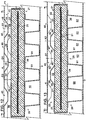
- the heater or radiator 1 comprises a casing 2 and a core 20 arranged inside the casing.
- the casing 2 may be made from sheet metal, advantageously sheet aluminium, comprising a front panel 3 which defines the front side of the heater, and a rear panel 4 which defines a rear surface of the casing.
- the front and rear panels may be joined by internal sides 5 which are covered by end covers 6.
- a top cover 7 with air vents 8 is arranged over the top of the vertical panels.
- the casing is provided with feet 9 which support the lower end of the casing above the level of the floor, the lower end defining an opening 10 through which air can flow into the casing at the base.
- the casing also has supports 11 which are used with suitable brackets or other wall fixings (not shown) as known in the art to support the heater on a wall 12 with the rear surface in spaced parallel relation to the wall as shown in Fig. 11 .
- the core 20 may comprise a casing 21, which may be made for example from aluminium or other sheet metal, having a rear part 22 which defines a first, rearwardly facing outward side 23 of the core, and a front part 24 which defines a second, frontwardly facing outward side 25 opposite the first outward side.
- the first and second parts may be formed as two shallow trays with fit together with their sidewalls in overlapping relation to form a shell which encloses the thermal mass 30 between the front and rear sides 25, 23.
- the thermal mass 30 may comprise any suitable material that can store heat and release it at a comfortable temperature, for example, a compressed block of mineral powder such as soapstone.
- An electric element 31 is arranged to heat the thermal mass 30, conveniently by embedding the element inside the block.
- a power conductor 32 is arranged in communication with suitable thermostatic controls or other temperature sensing and control means (not shown) as known in the art for sensing the temperature of the core and/or the temperature of the air in the room to energise the element and control the temperature of the core so as to emit heat at a comfortable temperature by radiation and convection through the casing.
- the rearwardly facing outward side 23 of the core defines a plurality of first protrusions 26 which are spaced apart in two (respectively, vertical and horizontal) dimensions to form a spaced array as shown in Fig. 5 .
- the first protrusions may be formed as locally indented regions of a generally flat sheet metal panel 27 forming the major surface of the rear part 22 of the casing.
- Each first protrusion may extend outwardly from the flat surface 27' of the panel 27 as shown along an axis X2 to define a frustoconical sidewall 28 defining a surface of revolution about the axis X2 with a flat top surface 29 normal to the axis X2 and so parallel with the convection plane P1 and the flat surface 27' of the panel 27.
- the two dimensions defining the spaced array extend in the major flat surface plane 27' of the panel 27 parallel with the convection plane P1, hence in the plane of the drawing as shown in Fig. 5 .
- the thermal mass 30 may be arranged as shown in the sheet metal casing 21 in contact with regions of the sheet metal panel 27 defining on its outward side 23 its flat surface 27' proximate the first protrusions 26, a void 33 being formed between the thermal mass 30 and each of the first protrusions 26 as shown.
- the intimate contact between the flat portion of the panel 27 and the thermal mass 30 is found to effectively transfer heat to the first protrusions 26 and hence to the air which impinges on the first protrusions as it flows through the convection space 50.
- the heat transfer from the core to the first protrusions is particularly effective when the panel 27 is made from aluminium, providing an effective but economical construction which makes it possible to form the thermal mass 30 by pressing as a simple, rectilinear block.
- the rear panel 4 may be formed from sheet metal, e.g. sheet aluminium, and is locally indented to define a plurality of recesses 43 which are spaced apart in two (respectively, vertical and horizontal) dimensions to form a spaced array on the first side 40 of the panel.
- the opposite, first and second sides 40, 41 of the rear panel 4 may be generally flat in the regions between the recesses 43 to extend in parallel with the convection plane P1, hence defining a flat surface 47 on its second side 41 in-between the second protrusions 44.
- the two dimensions defining the spaced array extend in the major plane of the panel 4 and parallel with the convection plane P1, hence in the plane of the drawing as shown in Fig. 3 .
- Each recess 43 extends along a recess axis X1 towards the first outward side 23 of the core to define a second protrusion 44 on the second side 41 of the panel.
- Each recess has a recess sidewall 45 and a recess base wall 46, the recess sidewall 45 surrounding the recess axis X1 and extending towards the first outward side 23 of the core and terminating at the recess base wall 46 as best seen in Figs. 11 , 12 and 13 .
- Each recess sidewall 45 may define a frustoconical surface of revolution about the respective recess axis X1 as shown.
- a perforation 48 is formed, conveniently as a circular hole as shown, in each recess base wall 46 so that it extends along the recess axis X1 between the first and second sides 40, 41 of the panel 4.
- the core 20 is arranged in the casing 2 as shown so that each recess base wall 46 is spaced apart from the first outward side 23 of the core by a separation distance D1 ( Fig. 12 ).
- the flat surfaces 47 and 27' are spaced apart in opposed relation on opposite sides of a nominal convection plane P1 ( Fig. 12 ) lying in a convection space 50 between the rear panel 4 and the core 20. In the installed position of the heater the convection plane P1 is vertical and parallel with the wall 12 ( Fig. 11 ).
- the first protrusions 26 When the first and second protrusions 26, 44 are projected onto the convection plane P1, the first protrusions 26 are arranged in-between the second protrusions 44 in the convection plane P1 so that the convection space 50 defines a serpentine flowpath between respective adjacent ones of the first and second protrusions 26, 44.
- the first and second protrusions 26, 44 may intersect the convection plane. This improves the effectiveness of the serpentine flowpath so that air cannot flow in a straight line in the convection plane P1 between the first and second protrusions, but rather is diverted around each protrusion.
- the projected positions of the first and second protrusions can be seen in Fig. 12 which shows how both sets of protrusions intersect the convection plane P1; if in alternative embodiments the protrusions 26, 44 are arranged entirely on opposite sides of the nominal convection plane P1 they can nevertheless be projected onto the convection plane plane in a direction normal to the convection plane, so that when viewed in the convection plane the two sets of first and second projections 26, 44 can be seen to be arranged in-between one another as shown in Fig. 7 .
- the serpentine flowpath may increase thermal transfer by causing the air to impinge on the first protrusions 26 and by increasing the length of the flowpath and hence the residence time of the air within the convection space 50.
- the mass flow rate may increase progressively towards the top of the convection space 50 and so velocity may also increase, which in turn accentuates the pressure differential driving more air into the convection space towards the upper end of the structure.
- the novel structure thus generates a surprisingly effective convective airflow in a very slim space with a maximum thickness dimension D2.
- D1 may be less than D2.
- D1 may be less than 0.5 ⁇ D2.
- D1 may be about 0.4 ⁇ D2 as shown, or about 0.3 ⁇ D2, or even less.
- the distance D1 may be in the range from about 5mm to about 15mm, for example, about 1cm.
- the front panel 3 of the casing 2 is spaced apart from the core 20 to define a front convector space 60 between the front panel 3 and the core 20.
- a convector structure is arranged in the front convector space 60, the convector structure comprising a plurality of walls 61 extending between the second, frontwardly facing outward side 25 of the core and the front panel 3 of the casing, the walls 61 being spaced apart to divide the front convector space into a plurality of channels 62.
- the walls 61 are separate from the front panel 3, they could be incorporated into the front panel 3 so that the front panel 3 has a visible structure of vertical joints. Of course, other constructions are possible.
- the convection space 50 may include a lower region 51 and an upper region 52, wherein in use, air heated in the lower region 51 flows upwardly into the upper region 52, and wherein the first and second protrusions extend into the lower region 51 but not the upper region 52.
- the novel heater 1 When the novel heater 1 is mounted on a wall 12 with its rear surface in spaced parallel relation to the wall as shown in Fig. 11 , the air drawn through the perforations 48 into the convection space 50 causes cooler air to flow upwardly from floor level and inwardly into the space between the rear surface of the heater and the wall.
- the maximum temperature of the wall surface behind the heater 1 remains surprisingly low while the heater is in use, being only slightly higher than that measured at some horizontal distance from the heater 1.
- the novel heater loses very little heat to the wall.
- the strong convective airflow generated by the novel heater is found to reduce the surface temperature of the casing 2 to a surprisingly low temperature, so that the novel heater may be suitable for use where conventional heaters with higher surface temperatures would present a risk of injury to vulnerable users.
- the recess base wall 46 is defined by an inwardly facing surface, which is to say, a surface facing towards the core 20, which may be formed (wholly or in part) by the thickness of the recess sidewall 45.
- the recess base wall 46 may also define a rearwardly facing surface, i.e. a surface facing away from the core 20, as shown.
- the perforations 48 may be made somewhat larger than illustrated, for example, extending up to most or all of the radially inner dimension (or diameter) of the recess 43 at the recess base wall 46, in which case the recess base wall 46 may not have a rearwardly facing surface.
- the surface temperature of the front face of the heater may be further reduced by increasing the number of walls 61 to further subdivide the front convector space 60, thus strengthening the convection in the channels 62.
- the vertical (height) dimension of the upper region 52 may be somewhat greater than illustrated.
- the upper region 52 may be about 150mm in height.
- the vertically elongated upper region 52 acts as a chimney whicih further strengthens the convective airflow through the convection space 50.
- further perforations may be provided in the rear panel 4 opening into the upper region 52 of the convection space 50. This further increases the airflow drawn into the convection space 50 from the space between the heater 1 and the wall 12.
- the maximum wall surface temperature behind the heater 1 may be as little as 0.5°C higher than that measured at a horizontal distance of 1.5m away from the heater 1.
- a wall mountable electric heater comprises a core 20 arranged in a casing 2 with a convection space 50 defined between opposed surfaces 47, 27' of the casing and the core.
- the opposed surfaces are provided with oppositely directed protrusions 26, 44 which are spaced apart in two dimensions and arranged in-between one another to form a serpentine flowpath.
- the protrusions 44 in the panel 4 of the casing define recesses 43 which extend inwardly towards the core, each recess having a base wall 46 in which a perforation 48 is formed between the first and second sides 40, 41 of the panel 4.
- the air flowing upwardly through the convection space 50 generates a pressure differential across the first and second sides 40, 41 of the panel 4, drawing air in through the perforations 48 to increase the mass flow rate of the air in the convection space.
- the base wall 46 of each recess may be spaced apart from the opposed, outwardly facing side 23 of the core by a relatively small distance D1, increasing the velocity of the airflow and hence the pressure differential proximate the perforation 48.
- the panel defining the recesses may be arranged other than at the rear surface of the casing.
- two panels defining recesses and protrusions might be arranged, one in front and one behind the core, with the frontwardly facing side of the core also defining an array of protrusions similar to the first protrusions, to define two parallel convection spaces, each having a slim thickness dimension D2 as described above, to further reduce the overall thickness of the heater.
- the first protrusions and the recesses defining the second protrusions could be formed by pressing, moulding or any other suitable process.
- the recesses and first and second protrusions could be other than frustoconical.
- the thermal mass could be pressed, moulded, cut or otherwise formed to define the first protrusions.
- the surface of the thermal mass could be exposed at the convection space without the use of a sheet metal casing,
- the thermal mass could be a solid or liquid material.
- the overall form factor of the heater can be selected to suit the intended use position, being relatively taller and narrower or shorter and wider than that illustrated.
Landscapes
- Engineering & Computer Science (AREA)
- Physics & Mathematics (AREA)
- Thermal Sciences (AREA)
- Chemical & Material Sciences (AREA)
- Combustion & Propulsion (AREA)
- Mechanical Engineering (AREA)
- General Engineering & Computer Science (AREA)
- Central Heating Systems (AREA)
Claims (9)
- Dispositif de chauffage électrique pouvant être monté sur un mur (1) comprenant un carter (2) et un noyau (20) agencé dans le carter (2) ;le carter (2) comprenant un panneau (4), le panneau (4) ayant des premier et second côtés (40, 41) opposés ;le noyau (20) comprenant un premier côté extérieur (23), une masse thermique (30) et un élément électrique (31) agencé pour chauffer la masse thermique (30) ;des surfaces (47, 27') respectives du second côté (41) du panneau (4) et du premier côté extérieur (23) du noyau (20) étant espacées en relation opposée sur les côtés opposés d'un plan de convection nominal (P1) se trouvant dans un espace de convection (50) entre le panneau (4) et le noyau (20) ; caractérisé en ce que :le premier côté extérieur (23) du noyau (20) a une pluralité de premières saillies (26), les premières saillies (26) étant espacées dans deux dimensions pour former un réseau espacé ;le panneau (4) ayant une pluralité d'évidements (43), les évidements (43) étant espacés dans deux dimensions pour former un réseau espacé du premier côté (40) du panneau (4) ;chaque évidement (43) s'étendant le long d'un axe d'évidement (X1) vers le premier côté extérieur (23) du noyau (20) afin de définir une seconde saillie (44) sur le second côté (41) du panneau (4) ;chaque évidement (43) ayant une paroi latérale d'évidement (45) et une paroi de base d'évidement (46), la paroi latérale d'évidement (45) entourant l'axe d'évidement (X1) et s'étendant vers le premier côté extérieur (23) du noyau (20) et se terminant au niveau de la paroi de base d'évidement (46), la paroi de base d'évidement (46) étant espacée du premier côté extérieur (23) du noyau (20) par une distance de séparation D1 ;dans lequel lorsque les première et seconde saillies (26, 44) font saillie sur le plan de convection (P1), les premières saillies (26) sont agencées entre les secondes saillies (44) dans le plan de convection (P1) de sorte que l'espace de convection (50) définit une trajectoire d'écoulement en serpentin entre les saillies adjacentes respectives des première et seconde saillies (26, 44) ;et une perforation (48) est formée dans chaque paroi de base d'évidement (46) entre les premier et second côtés (40, 41) du panneau (4).
- Dispositif de chauffage électrique pouvant être monté sur un mur (1) selon la revendication 1, dans lequel les première et seconde saillies (26, 44) coupent le plan de convection (P1).
- Dispositif de chauffage électrique pouvant être monté sur un mur (1) selon la revendication 1, dans lequel lesdites surfaces (47, 27') respectives du second côté (41) du panneau (4) et du premier côté extérieur (23) du noyau (20) sont espacées par une distance D2 en relation opposée sur les côtés opposés du plan de convection (P1) ;
et D1 < D2. - Dispositif de chauffage électrique pouvant être monté sur un mur (1) selon la revendication 3, dans lequel D1 < 0,5·D2.
- Dispositif de chauffage électrique pouvant être monté sur un mur (1) selon la revendication 1, dans lequel chaque paroi latérale d'évidement (45) définit une surface tronconique de révolution autour de l'axe d'évidement (X1) respectif.
- Dispositif de chauffage électrique pouvant être monté sur un mur (1) selon la revendication 1, dans lequel le panneau (4) définit une surface arrière du carter (2) et le dispositif de chauffage (1) comprend des supports (11) pour supporter le dispositif de chauffage (1) sur un mur (12) avec la surface arrière en relation parallèle espacée par rapport au mur (12).
- Dispositif de chauffage électrique pouvant être monté sur un mur (1) selon la revendication 6, dans lequel le noyau (20) a un second côté extérieur (25) opposé au premier côté extérieur (23) et le carter (2) comprend un panneau avant (3), le panneau avant (3) définissant un côté avant du dispositif de chauffage (1) et étant espacé du noyau (20) afin de définir un espace de convecteur avant (60) entre le panneau avant (3) et le noyau (20) ; et une structure de convecteur est agencée dans l'espace de convecteur avant (60), la structure de convecteur comprenant une pluralité de parois (61) s'étendant entre le second côté extérieur (25) du noyau (20) et le panneau avant (3) du carter (2), les parois (61) étant espacées pour diviser l'espace de convecteur avant (60) en une pluralité de canaux (62) .
- Dispositif de chauffage électrique pouvant être monté sur un mur (1) selon la revendication 1, dans lequel le noyau (20) comprend un carter de métal en feuille (21), les premières saillies (26) comprenant des régions localement indentées d'un panneau de métal en feuille (27) du carter de métal en feuille (21) ;
la masse thermique (30) étant agencée dans le carter de métal en feuille (21) en contact avec des régions du panneau de métal en feuille (27) à proximité des premières saillies (26), un vide (33) étant formé entre la masse thermique (30) et chacune des premières saillies (26). - Dispositif de chauffage électrique pouvant être monté sur un mur (1) selon la revendication 8, dans lequel la masse thermique (30) comprend une poudre minérale comprimée.
Applications Claiming Priority (2)
| Application Number | Priority Date | Filing Date | Title |
|---|---|---|---|
| GBGB1804373.7A GB201804373D0 (en) | 2018-03-19 | 2018-03-19 | Wall mountable electric heater with slim form factor |
| PCT/GB2019/050762 WO2019180418A1 (fr) | 2018-03-19 | 2019-03-19 | Dispositif de chauffage électrique pouvant être monté sur un mur avec un facteur de forme mince |
Publications (2)
| Publication Number | Publication Date |
|---|---|
| EP3769016A1 EP3769016A1 (fr) | 2021-01-27 |
| EP3769016B1 true EP3769016B1 (fr) | 2021-12-15 |
Family
ID=62018014
Family Applications (1)
| Application Number | Title | Priority Date | Filing Date |
|---|---|---|---|
| EP19714725.9A Active EP3769016B1 (fr) | 2018-03-19 | 2019-03-19 | Dispositif de chauffage électrique pouvant être monté sur un mur avec un facteur de forme mince |
Country Status (7)
| Country | Link |
|---|---|
| US (1) | US11841168B2 (fr) |
| EP (1) | EP3769016B1 (fr) |
| CA (1) | CA3093953A1 (fr) |
| ES (1) | ES2914408T3 (fr) |
| GB (1) | GB201804373D0 (fr) |
| PT (1) | PT3769016T (fr) |
| WO (1) | WO2019180418A1 (fr) |
Family Cites Families (8)
| Publication number | Priority date | Publication date | Assignee | Title |
|---|---|---|---|---|
| DE1579786B2 (de) * | 1965-12-16 | 1974-01-03 | Witte Haustechnik Gmbh, 5860 Iserlohn | Elektrisches Wärmespeicherheizgerät mit einem Entladegebläse |
| DE3636740A1 (de) | 1986-10-29 | 1988-05-05 | Kueppersbusch | Speicherheizgeraet |
| ATE68871T1 (de) * | 1988-05-31 | 1991-11-15 | Everken Olsberger Huette Kg | Elektrospeicherheizgeraet. |
| GB2265705B (en) * | 1992-03-04 | 1995-11-29 | Dimplex | Storage heater |
| DE10007793A1 (de) * | 2000-02-21 | 2001-08-23 | Olsberg Hermann Everken Gmbh | Elektro-Speicherheizgerät |
| DE102013208284A1 (de) * | 2013-05-06 | 2014-11-06 | Fraunhofer-Gesellschaft zur Förderung der angewandten Forschung e.V. | Wärmedämmplatte und Verfahren zur Montage von Leitungen |
| IT201600114685A1 (it) * | 2016-11-14 | 2018-05-14 | Silcart Spa | Dispositivo per il supporto e fissaggio di condutture riscaldanti di un sistema di riscaldamento collocato in sottopavimenti, pareti o soffitti di edifici |
| KR102482688B1 (ko) * | 2022-07-07 | 2022-12-29 | 신경철 | 손쉬운 분해조립 구조를 포함하는 조립식 1인 찜질방 |
-
2018
- 2018-03-19 GB GBGB1804373.7A patent/GB201804373D0/en not_active Ceased
-
2019
- 2019-03-19 PT PT197147259T patent/PT3769016T/pt unknown
- 2019-03-19 US US16/982,144 patent/US11841168B2/en active Active
- 2019-03-19 WO PCT/GB2019/050762 patent/WO2019180418A1/fr not_active Ceased
- 2019-03-19 ES ES19714725T patent/ES2914408T3/es active Active
- 2019-03-19 CA CA3093953A patent/CA3093953A1/fr active Pending
- 2019-03-19 EP EP19714725.9A patent/EP3769016B1/fr active Active
Also Published As
| Publication number | Publication date |
|---|---|
| WO2019180418A1 (fr) | 2019-09-26 |
| CA3093953A1 (fr) | 2019-09-26 |
| US11841168B2 (en) | 2023-12-12 |
| ES2914408T3 (es) | 2022-06-10 |
| PT3769016T (pt) | 2022-03-29 |
| US20210372663A1 (en) | 2021-12-02 |
| EP3769016A1 (fr) | 2021-01-27 |
| GB201804373D0 (en) | 2018-05-02 |
Similar Documents
| Publication | Publication Date | Title |
|---|---|---|
| CN107684340B (zh) | 电压力锅 | |
| CN212390501U (zh) | 空调室内机 | |
| KR20150025221A (ko) | 차량용 히터 장치 | |
| EP0783653A1 (fr) | Radiateurs | |
| US6901213B2 (en) | Electric heater | |
| CN111649358B (zh) | 一种静音电热炉 | |
| US1651890A (en) | Convection heater | |
| EP3769016B1 (fr) | Dispositif de chauffage électrique pouvant être monté sur un mur avec un facteur de forme mince | |
| KR20200001006A (ko) | 히팅모듈 및 그 커버부재와 이를 포함하는 히팅 시스템 | |
| US20110057047A1 (en) | Hot air heater | |
| CN212430953U (zh) | 一种静音电热炉 | |
| CN108317596B (zh) | 一种用于加热器上的控制盒及取暖器 | |
| EP0797056B1 (fr) | Radiateur à huile dont les bords sont maintenus à basse température | |
| KR102230541B1 (ko) | 난방용 벽판넬 | |
| EP2908060B1 (fr) | Appareil de chauffage à faible température de surface (LST) | |
| CN212057408U (zh) | 一种电热炉用的隔热结构 | |
| JP3931821B2 (ja) | 誘導加熱調理器 | |
| KR20180110327A (ko) | 방열 성능이 향상된 전기스토브 | |
| CN208920184U (zh) | 取暖器 | |
| CN218355835U (zh) | 一种具有新型散热风道结构的烤箱 | |
| CN223399814U (zh) | 一种电磁炉散热用风道及带有该风道的超薄电磁炉 | |
| CN218672333U (zh) | 电暖气 | |
| CN212029632U (zh) | 一种电热炉的隔热结构 | |
| JP3717738B2 (ja) | 熱板式グリル | |
| KR102125699B1 (ko) | 축열식 온풍 겸용 라디에이터 난방장치 |
Legal Events
| Date | Code | Title | Description |
|---|---|---|---|
| STAA | Information on the status of an ep patent application or granted ep patent |
Free format text: STATUS: UNKNOWN |
|
| STAA | Information on the status of an ep patent application or granted ep patent |
Free format text: STATUS: THE INTERNATIONAL PUBLICATION HAS BEEN MADE |
|
| PUAI | Public reference made under article 153(3) epc to a published international application that has entered the european phase |
Free format text: ORIGINAL CODE: 0009012 |
|
| STAA | Information on the status of an ep patent application or granted ep patent |
Free format text: STATUS: REQUEST FOR EXAMINATION WAS MADE |
|
| 17P | Request for examination filed |
Effective date: 20200907 |
|
| AK | Designated contracting states |
Kind code of ref document: A1 Designated state(s): AL AT BE BG CH CY CZ DE DK EE ES FI FR GB GR HR HU IE IS IT LI LT LU LV MC MK MT NL NO PL PT RO RS SE SI SK SM TR |
|
| AX | Request for extension of the european patent |
Extension state: BA ME |
|
| DAV | Request for validation of the european patent (deleted) | ||
| DAX | Request for extension of the european patent (deleted) | ||
| GRAP | Despatch of communication of intention to grant a patent |
Free format text: ORIGINAL CODE: EPIDOSNIGR1 |
|
| STAA | Information on the status of an ep patent application or granted ep patent |
Free format text: STATUS: GRANT OF PATENT IS INTENDED |
|
| INTG | Intention to grant announced |
Effective date: 20210907 |
|
| GRAS | Grant fee paid |
Free format text: ORIGINAL CODE: EPIDOSNIGR3 |
|
| GRAA | (expected) grant |
Free format text: ORIGINAL CODE: 0009210 |
|
| STAA | Information on the status of an ep patent application or granted ep patent |
Free format text: STATUS: THE PATENT HAS BEEN GRANTED |
|
| AK | Designated contracting states |
Kind code of ref document: B1 Designated state(s): AL AT BE BG CH CY CZ DE DK EE ES FI FR GB GR HR HU IE IS IT LI LT LU LV MC MK MT NL NO PL PT RO RS SE SI SK SM TR |
|
| REG | Reference to a national code |
Ref country code: GB Ref legal event code: FG4D Ref country code: CH Ref legal event code: EP |
|
| REG | Reference to a national code |
Ref country code: IE Ref legal event code: FG4D Ref country code: DE Ref legal event code: R096 Ref document number: 602019010110 Country of ref document: DE |
|
| REG | Reference to a national code |
Ref country code: AT Ref legal event code: REF Ref document number: 1455761 Country of ref document: AT Kind code of ref document: T Effective date: 20220115 |
|
| REG | Reference to a national code |
Ref country code: PT Ref legal event code: SC4A Ref document number: 3769016 Country of ref document: PT Date of ref document: 20220329 Kind code of ref document: T Free format text: AVAILABILITY OF NATIONAL TRANSLATION Effective date: 20220322 |
|
| REG | Reference to a national code |
Ref country code: LT Ref legal event code: MG9D |
|
| REG | Reference to a national code |
Ref country code: NL Ref legal event code: MP Effective date: 20211215 |
|
| PG25 | Lapsed in a contracting state [announced via postgrant information from national office to epo] |
Ref country code: RS Free format text: LAPSE BECAUSE OF FAILURE TO SUBMIT A TRANSLATION OF THE DESCRIPTION OR TO PAY THE FEE WITHIN THE PRESCRIBED TIME-LIMIT Effective date: 20211215 Ref country code: LT Free format text: LAPSE BECAUSE OF FAILURE TO SUBMIT A TRANSLATION OF THE DESCRIPTION OR TO PAY THE FEE WITHIN THE PRESCRIBED TIME-LIMIT Effective date: 20211215 Ref country code: FI Free format text: LAPSE BECAUSE OF FAILURE TO SUBMIT A TRANSLATION OF THE DESCRIPTION OR TO PAY THE FEE WITHIN THE PRESCRIBED TIME-LIMIT Effective date: 20211215 Ref country code: BG Free format text: LAPSE BECAUSE OF FAILURE TO SUBMIT A TRANSLATION OF THE DESCRIPTION OR TO PAY THE FEE WITHIN THE PRESCRIBED TIME-LIMIT Effective date: 20220315 |
|
| REG | Reference to a national code |
Ref country code: GR Ref legal event code: EP Ref document number: 20220400596 Country of ref document: GR Effective date: 20220418 |
|
| REG | Reference to a national code |
Ref country code: AT Ref legal event code: MK05 Ref document number: 1455761 Country of ref document: AT Kind code of ref document: T Effective date: 20211215 |
|
| PG25 | Lapsed in a contracting state [announced via postgrant information from national office to epo] |
Ref country code: SE Free format text: LAPSE BECAUSE OF FAILURE TO SUBMIT A TRANSLATION OF THE DESCRIPTION OR TO PAY THE FEE WITHIN THE PRESCRIBED TIME-LIMIT Effective date: 20211215 Ref country code: NO Free format text: LAPSE BECAUSE OF FAILURE TO SUBMIT A TRANSLATION OF THE DESCRIPTION OR TO PAY THE FEE WITHIN THE PRESCRIBED TIME-LIMIT Effective date: 20220315 Ref country code: LV Free format text: LAPSE BECAUSE OF FAILURE TO SUBMIT A TRANSLATION OF THE DESCRIPTION OR TO PAY THE FEE WITHIN THE PRESCRIBED TIME-LIMIT Effective date: 20211215 Ref country code: HR Free format text: LAPSE BECAUSE OF FAILURE TO SUBMIT A TRANSLATION OF THE DESCRIPTION OR TO PAY THE FEE WITHIN THE PRESCRIBED TIME-LIMIT Effective date: 20211215 |
|
| REG | Reference to a national code |
Ref country code: ES Ref legal event code: FG2A Ref document number: 2914408 Country of ref document: ES Kind code of ref document: T3 Effective date: 20220610 |
|
| PG25 | Lapsed in a contracting state [announced via postgrant information from national office to epo] |
Ref country code: NL Free format text: LAPSE BECAUSE OF FAILURE TO SUBMIT A TRANSLATION OF THE DESCRIPTION OR TO PAY THE FEE WITHIN THE PRESCRIBED TIME-LIMIT Effective date: 20211215 |
|
| PG25 | Lapsed in a contracting state [announced via postgrant information from national office to epo] |
Ref country code: SM Free format text: LAPSE BECAUSE OF FAILURE TO SUBMIT A TRANSLATION OF THE DESCRIPTION OR TO PAY THE FEE WITHIN THE PRESCRIBED TIME-LIMIT Effective date: 20211215 Ref country code: SK Free format text: LAPSE BECAUSE OF FAILURE TO SUBMIT A TRANSLATION OF THE DESCRIPTION OR TO PAY THE FEE WITHIN THE PRESCRIBED TIME-LIMIT Effective date: 20211215 Ref country code: RO Free format text: LAPSE BECAUSE OF FAILURE TO SUBMIT A TRANSLATION OF THE DESCRIPTION OR TO PAY THE FEE WITHIN THE PRESCRIBED TIME-LIMIT Effective date: 20211215 Ref country code: EE Free format text: LAPSE BECAUSE OF FAILURE TO SUBMIT A TRANSLATION OF THE DESCRIPTION OR TO PAY THE FEE WITHIN THE PRESCRIBED TIME-LIMIT Effective date: 20211215 Ref country code: CZ Free format text: LAPSE BECAUSE OF FAILURE TO SUBMIT A TRANSLATION OF THE DESCRIPTION OR TO PAY THE FEE WITHIN THE PRESCRIBED TIME-LIMIT Effective date: 20211215 |
|
| PG25 | Lapsed in a contracting state [announced via postgrant information from national office to epo] |
Ref country code: PL Free format text: LAPSE BECAUSE OF FAILURE TO SUBMIT A TRANSLATION OF THE DESCRIPTION OR TO PAY THE FEE WITHIN THE PRESCRIBED TIME-LIMIT Effective date: 20211215 Ref country code: AT Free format text: LAPSE BECAUSE OF FAILURE TO SUBMIT A TRANSLATION OF THE DESCRIPTION OR TO PAY THE FEE WITHIN THE PRESCRIBED TIME-LIMIT Effective date: 20211215 |
|
| REG | Reference to a national code |
Ref country code: DE Ref legal event code: R097 Ref document number: 602019010110 Country of ref document: DE |
|
| PG25 | Lapsed in a contracting state [announced via postgrant information from national office to epo] |
Ref country code: IS Free format text: LAPSE BECAUSE OF FAILURE TO SUBMIT A TRANSLATION OF THE DESCRIPTION OR TO PAY THE FEE WITHIN THE PRESCRIBED TIME-LIMIT Effective date: 20220415 |
|
| PLBE | No opposition filed within time limit |
Free format text: ORIGINAL CODE: 0009261 |
|
| STAA | Information on the status of an ep patent application or granted ep patent |
Free format text: STATUS: NO OPPOSITION FILED WITHIN TIME LIMIT |
|
| PG25 | Lapsed in a contracting state [announced via postgrant information from national office to epo] |
Ref country code: MC Free format text: LAPSE BECAUSE OF FAILURE TO SUBMIT A TRANSLATION OF THE DESCRIPTION OR TO PAY THE FEE WITHIN THE PRESCRIBED TIME-LIMIT Effective date: 20211215 Ref country code: DK Free format text: LAPSE BECAUSE OF FAILURE TO SUBMIT A TRANSLATION OF THE DESCRIPTION OR TO PAY THE FEE WITHIN THE PRESCRIBED TIME-LIMIT Effective date: 20211215 Ref country code: AL Free format text: LAPSE BECAUSE OF FAILURE TO SUBMIT A TRANSLATION OF THE DESCRIPTION OR TO PAY THE FEE WITHIN THE PRESCRIBED TIME-LIMIT Effective date: 20211215 |
|
| REG | Reference to a national code |
Ref country code: CH Ref legal event code: PL |
|
| 26N | No opposition filed |
Effective date: 20220916 |
|
| PG25 | Lapsed in a contracting state [announced via postgrant information from national office to epo] |
Ref country code: LU Free format text: LAPSE BECAUSE OF NON-PAYMENT OF DUE FEES Effective date: 20220319 Ref country code: LI Free format text: LAPSE BECAUSE OF NON-PAYMENT OF DUE FEES Effective date: 20220331 Ref country code: CH Free format text: LAPSE BECAUSE OF NON-PAYMENT OF DUE FEES Effective date: 20220331 |
|
| PG25 | Lapsed in a contracting state [announced via postgrant information from national office to epo] |
Ref country code: MK Free format text: LAPSE BECAUSE OF FAILURE TO SUBMIT A TRANSLATION OF THE DESCRIPTION OR TO PAY THE FEE WITHIN THE PRESCRIBED TIME-LIMIT Effective date: 20211215 Ref country code: CY Free format text: LAPSE BECAUSE OF FAILURE TO SUBMIT A TRANSLATION OF THE DESCRIPTION OR TO PAY THE FEE WITHIN THE PRESCRIBED TIME-LIMIT Effective date: 20211215 |
|
| PG25 | Lapsed in a contracting state [announced via postgrant information from national office to epo] |
Ref country code: HU Free format text: LAPSE BECAUSE OF FAILURE TO SUBMIT A TRANSLATION OF THE DESCRIPTION OR TO PAY THE FEE WITHIN THE PRESCRIBED TIME-LIMIT; INVALID AB INITIO Effective date: 20190319 |
|
| PG25 | Lapsed in a contracting state [announced via postgrant information from national office to epo] |
Ref country code: TR Free format text: LAPSE BECAUSE OF FAILURE TO SUBMIT A TRANSLATION OF THE DESCRIPTION OR TO PAY THE FEE WITHIN THE PRESCRIBED TIME-LIMIT Effective date: 20211215 |
|
| PG25 | Lapsed in a contracting state [announced via postgrant information from national office to epo] |
Ref country code: MT Free format text: LAPSE BECAUSE OF FAILURE TO SUBMIT A TRANSLATION OF THE DESCRIPTION OR TO PAY THE FEE WITHIN THE PRESCRIBED TIME-LIMIT Effective date: 20211215 |
|
| PGFP | Annual fee paid to national office [announced via postgrant information from national office to epo] |
Ref country code: DE Payment date: 20250319 Year of fee payment: 7 |
|
| PGFP | Annual fee paid to national office [announced via postgrant information from national office to epo] |
Ref country code: IE Payment date: 20250321 Year of fee payment: 7 |
|
| PGFP | Annual fee paid to national office [announced via postgrant information from national office to epo] |
Ref country code: GR Payment date: 20250319 Year of fee payment: 7 Ref country code: BE Payment date: 20250320 Year of fee payment: 7 |
|
| PGFP | Annual fee paid to national office [announced via postgrant information from national office to epo] |
Ref country code: FR Payment date: 20250318 Year of fee payment: 7 |
|
| PGFP | Annual fee paid to national office [announced via postgrant information from national office to epo] |
Ref country code: GB Payment date: 20250324 Year of fee payment: 7 |
|
| PGFP | Annual fee paid to national office [announced via postgrant information from national office to epo] |
Ref country code: ES Payment date: 20250416 Year of fee payment: 7 |
|
| PGFP | Annual fee paid to national office [announced via postgrant information from national office to epo] |
Ref country code: IT Payment date: 20250331 Year of fee payment: 7 |
|
| PGFP | Annual fee paid to national office [announced via postgrant information from national office to epo] |
Ref country code: PT Payment date: 20250915 Year of fee payment: 7 |
|
| PG25 | Lapsed in a contracting state [announced via postgrant information from national office to epo] |
Ref country code: SI Free format text: LAPSE BECAUSE OF FAILURE TO SUBMIT A TRANSLATION OF THE DESCRIPTION OR TO PAY THE FEE WITHIN THE PRESCRIBED TIME-LIMIT Effective date: 20211215 |