EP3769703A1 - Dilatateur - Google Patents
Dilatateur Download PDFInfo
- Publication number
- EP3769703A1 EP3769703A1 EP18910960.6A EP18910960A EP3769703A1 EP 3769703 A1 EP3769703 A1 EP 3769703A1 EP 18910960 A EP18910960 A EP 18910960A EP 3769703 A1 EP3769703 A1 EP 3769703A1
- Authority
- EP
- European Patent Office
- Prior art keywords
- shaft
- coil
- distal end
- spirally
- dilator
- Prior art date
- Legal status (The legal status is an assumption and is not a legal conclusion. Google has not performed a legal analysis and makes no representation as to the accuracy of the status listed.)
- Granted
Links
Images


Classifications
-
- A—HUMAN NECESSITIES
- A61—MEDICAL OR VETERINARY SCIENCE; HYGIENE
- A61B—DIAGNOSIS; SURGERY; IDENTIFICATION
- A61B17/00—Surgical instruments, devices or methods
- A61B17/34—Trocars; Puncturing needles
- A61B17/3417—Details of tips or shafts, e.g. grooves, expandable, bendable; Multiple coaxial sliding cannulas, e.g. for dilating
-
- A—HUMAN NECESSITIES
- A61—MEDICAL OR VETERINARY SCIENCE; HYGIENE
- A61B—DIAGNOSIS; SURGERY; IDENTIFICATION
- A61B90/00—Instruments, implements or accessories specially adapted for surgery or diagnosis and not covered by any of the groups A61B1/00 - A61B50/00, e.g. for luxation treatment or for protecting wound edges
- A61B90/02—Devices for expanding tissue, e.g. skin tissue
-
- A—HUMAN NECESSITIES
- A61—MEDICAL OR VETERINARY SCIENCE; HYGIENE
- A61M—DEVICES FOR INTRODUCING MEDIA INTO, OR ONTO, THE BODY; DEVICES FOR TRANSDUCING BODY MEDIA OR FOR TAKING MEDIA FROM THE BODY; DEVICES FOR PRODUCING OR ENDING SLEEP OR STUPOR
- A61M25/00—Catheters; Hollow probes
- A61M25/0021—Catheters; Hollow probes characterised by the form of the tubing
- A61M25/0023—Catheters; Hollow probes characterised by the form of the tubing by the form of the lumen, e.g. cross-section, variable diameter
-
- A—HUMAN NECESSITIES
- A61—MEDICAL OR VETERINARY SCIENCE; HYGIENE
- A61M—DEVICES FOR INTRODUCING MEDIA INTO, OR ONTO, THE BODY; DEVICES FOR TRANSDUCING BODY MEDIA OR FOR TAKING MEDIA FROM THE BODY; DEVICES FOR PRODUCING OR ENDING SLEEP OR STUPOR
- A61M25/00—Catheters; Hollow probes
- A61M25/0043—Catheters; Hollow probes characterised by structural features
- A61M25/005—Catheters; Hollow probes characterised by structural features with embedded materials for reinforcement, e.g. wires, coils, braids
- A61M25/0053—Catheters; Hollow probes characterised by structural features with embedded materials for reinforcement, e.g. wires, coils, braids having a variable stiffness along the longitudinal axis, e.g. by varying the pitch of the coil or braid
-
- A—HUMAN NECESSITIES
- A61—MEDICAL OR VETERINARY SCIENCE; HYGIENE
- A61M—DEVICES FOR INTRODUCING MEDIA INTO, OR ONTO, THE BODY; DEVICES FOR TRANSDUCING BODY MEDIA OR FOR TAKING MEDIA FROM THE BODY; DEVICES FOR PRODUCING OR ENDING SLEEP OR STUPOR
- A61M29/00—Dilators with or without means for introducing media, e.g. remedies
-
- A—HUMAN NECESSITIES
- A61—MEDICAL OR VETERINARY SCIENCE; HYGIENE
- A61B—DIAGNOSIS; SURGERY; IDENTIFICATION
- A61B17/00—Surgical instruments, devices or methods
- A61B2017/00831—Material properties
- A61B2017/00902—Material properties transparent or translucent
- A61B2017/00915—Material properties transparent or translucent for radioactive radiation
-
- A—HUMAN NECESSITIES
- A61—MEDICAL OR VETERINARY SCIENCE; HYGIENE
- A61B—DIAGNOSIS; SURGERY; IDENTIFICATION
- A61B17/00—Surgical instruments, devices or methods
- A61B17/34—Trocars; Puncturing needles
- A61B17/3417—Details of tips or shafts, e.g. grooves, expandable, bendable; Multiple coaxial sliding cannulas, e.g. for dilating
- A61B2017/3454—Details of tips
- A61B2017/3456—Details of tips blunt
-
- A—HUMAN NECESSITIES
- A61—MEDICAL OR VETERINARY SCIENCE; HYGIENE
- A61B—DIAGNOSIS; SURGERY; IDENTIFICATION
- A61B17/00—Surgical instruments, devices or methods
- A61B17/34—Trocars; Puncturing needles
- A61B17/3417—Details of tips or shafts, e.g. grooves, expandable, bendable; Multiple coaxial sliding cannulas, e.g. for dilating
- A61B2017/3454—Details of tips
- A61B2017/3458—Details of tips threaded
-
- A—HUMAN NECESSITIES
- A61—MEDICAL OR VETERINARY SCIENCE; HYGIENE
- A61B—DIAGNOSIS; SURGERY; IDENTIFICATION
- A61B90/00—Instruments, implements or accessories specially adapted for surgery or diagnosis and not covered by any of the groups A61B1/00 - A61B50/00, e.g. for luxation treatment or for protecting wound edges
- A61B90/39—Markers, e.g. radio-opaque or breast lesions markers
- A61B2090/3966—Radiopaque markers visible in an X-ray image
-
- A—HUMAN NECESSITIES
- A61—MEDICAL OR VETERINARY SCIENCE; HYGIENE
- A61M—DEVICES FOR INTRODUCING MEDIA INTO, OR ONTO, THE BODY; DEVICES FOR TRANSDUCING BODY MEDIA OR FOR TAKING MEDIA FROM THE BODY; DEVICES FOR PRODUCING OR ENDING SLEEP OR STUPOR
- A61M25/00—Catheters; Hollow probes
- A61M25/0043—Catheters; Hollow probes characterised by structural features
- A61M2025/006—Catheters; Hollow probes characterised by structural features having a special surface topography or special surface properties, e.g. roughened or knurled surface
-
- A—HUMAN NECESSITIES
- A61—MEDICAL OR VETERINARY SCIENCE; HYGIENE
- A61M—DEVICES FOR INTRODUCING MEDIA INTO, OR ONTO, THE BODY; DEVICES FOR TRANSDUCING BODY MEDIA OR FOR TAKING MEDIA FROM THE BODY; DEVICES FOR PRODUCING OR ENDING SLEEP OR STUPOR
- A61M25/00—Catheters; Hollow probes
- A61M25/01—Introducing, guiding, advancing, emplacing or holding catheters
- A61M25/06—Body-piercing guide needles or the like
- A61M25/0662—Guide tubes
- A61M2025/0687—Guide tubes having means for atraumatic insertion in the body or protection of the tip of the sheath during insertion, e.g. special designs of dilators, needles or sheaths
-
- A—HUMAN NECESSITIES
- A61—MEDICAL OR VETERINARY SCIENCE; HYGIENE
- A61M—DEVICES FOR INTRODUCING MEDIA INTO, OR ONTO, THE BODY; DEVICES FOR TRANSDUCING BODY MEDIA OR FOR TAKING MEDIA FROM THE BODY; DEVICES FOR PRODUCING OR ENDING SLEEP OR STUPOR
- A61M25/00—Catheters; Hollow probes
- A61M25/0043—Catheters; Hollow probes characterised by structural features
- A61M25/005—Catheters; Hollow probes characterised by structural features with embedded materials for reinforcement, e.g. wires, coils, braids
Definitions
- the present invention relates to a dilator.
- Dilators that enable treatment by enlarging a penetration-hole formed in the wall of a patient's digestive tract or the like are known.
- the distal end of the dilator is inserted into the penetration-hole formed in the wall, and the penetration-hole is expanded by pushing a tapered part into the penetration-hole.
- Such a dilator is disclosed in Patent Literature 1, for example.
- Patent Literature 1 Japanese Unexamined Patent Application Publication No. 2008-11867
- the present invention has an object of providing a dilator that suppresses unnecessary rotation and can easily widen the diameter of a penetration-hole formed in the wall of a digestive tract or the like.
- a dilator comprises a shaft in a hollow shape, in which an outer diameter of a distal end is smaller than an outer diameter of a proximal end, and a grip part that is provided on the proximal end of the shaft.
- a spirally-arranged protruding portion that protrudes toward an exterior is provided on an outer peripheral face of the shaft, and the spirally-arranged protruding portion has gaps in sections that are neighboring along an axis of the shaft.
- the shaft has, along the axis, a first location and a second location that is located closer to the distal end than the first location and has an outer diameter smaller than an outer diameter at the first location, and the spirally-arranged protruding portion has, with respect to the axis, an angle of inclination that is larger at the second location than at the first location.
- a section of the shaft on a distal end side may have a tapered shape whose outer diameter decreases toward the distal end.
- the shaft may include a first coil formed of a wire wound around in a hollow shape.
- the spirally-arranged protruding portion may include a second coil formed of a wire wound around onto the outer peripheral face of the shaft.
- the shaft may include a first coil formed of a wire wound around in a hollow shape
- the spirally-arranged protruding portion may include a second coil formed of a wire wound around onto the outer peripheral face of the shaft, and the wire of the first coil and the wire of the second coil may be wound in mutually opposite directions.
- a dilator can be provided that suppresses unnecessary rotation and can easily widen the diameter of a penetration-hole formed in the wall of a digestive tract or the like.
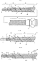
- FIG. 1 is an overall view of a dilator 1 according to a first embodiment of the present invention.
- the left side of the drawing is the distal end side (distal side) inserted into the body, and the right side is the proximal end side (proximal side) operated by an operator such as a physician.
- the dilator 1 comprises: a multilayered body 7 including a first coil 3 formed by winding a plurality of metal wires into a hollow shape, and a second coil 5 formed by winding a single metal wire onto an outer peripheral face 3A of the first coil 3 in an opposite direction (wound clockwise toward the distal end) to the first coil 3 (wound counterclockwise toward the distal end); and a hollow connector 9 connected to a proximal end of the multilayered body 7.
- the wires constituting the first coil 3 and the second coil 5 are, for example, metal wires made of stainless steel or a superelastic alloy such as nickel-titanium, or are resin wires.
- the first coil 3 is formed, for example, by winding ten metal wires made of stainless steel.
- the first coil 3 has a hollow shape and is formed having a lumen 3B that passes through from the distal end to the proximal end.
- the first coil 3 includes a body portion 3C, a tapered part 3D, and a distal end part 3E.
- the first coil 3 corresponds to a shaft.
- the body portion 3C is located on the proximal end side of the dilator 1, and a connector 9 is connected to the proximal end thereof. Furthermore, the body portion 3C has a substantially constant outer diameter from the proximal end to the distal end.
- the tapered part 3D is located on the distal end side of the body portion 3C, extends from the distal end of the body portion 3C toward the distal end side, and has an outer diameter that decreases toward the distal end side.
- the tapered part 3D corresponds to a section of the distal end side of the shaft.
- the distal end part 3E is located on the distal end side of the tapered part 3D and extends from the distal end of the tapered part 3D toward the distal end side.
- the distal end part 3E has a substantially constant outer diameter from the proximal end to the distal end.
- the first coil 3, which serves as the shaft, has a hollow shape in which the outer diameter of the distal end is smaller than the outer diameter of the proximal end.
- the second coil 5 is, for example, a single metal wire which is wound around onto the outer peripheral face 3A of the first coil 3 in an opposite direction (wound clockwise toward the distal end) to the first coil 3 (wound counterclockwise toward the distal end).
- the metal wire is closely wound on the proximal end side, and is wound with spacing on the distal end side of the body portion 3C, the tapered part 3D, and the distal end part 3E.
- a spirally-arranged protruding portion that protrudes toward the exterior (from the outermost surface and outermost part of the dilator 1) is provided on the outer peripheral face 3A of the first coil 3 as a result of the section of the second coil 5 being wound with spacing.
- the spirally-arranged protruding portion has gaps in sections that are neighboring (metal wires that are neighboring) along the axis A of the first coil 3.
- the dilator 1 can also be moved forward by a rotation operation of the dilator 1 as a result of a screw action of the spirally-arranged protruding portion.
- the second coil 5 is configured such that, in the section which is provided with a mutual separation along the axis A, the angle of inclination with respect to the axis A of the first coil 3 gradually increases from the body portion 3C through the tapered part 3D to the distal end part 3E.
- ⁇ 1 to ⁇ 4 in FIG. 1 are set such that ⁇ 4 > ⁇ 3 > ⁇ 2 > ⁇ 1. That is to say, along the axis A, the angle of inclination at the second location P2 is larger than the angle of inclination at the first location P1.
- the second location P2 is located further to the distal end side than the first location P1 and has a smaller outer diameter than the outer diameter at the first location P1.
- the metal wire of the second coil 5 is wound such that the amount of spaces between neighboring metal wires gradually decreases toward the proximal end side of the body portion 3C.
- the rigidity of the dilator 1 (multilayered body 7) in the axial direction can be gradually changed, and the dilator 1 can easily advance along a path even when a curved path is to be travelled.
- the length of the dilator in the present embodiment and in the other embodiments described below is, for example, 2000 mm, and preferably 1600 mm to 2500 mm
- the length of the distal end part 3E is, for example, 10 mm, and preferably 0 to 100 mm
- the length of the tapered part 3D is, for example, 30 mm, and preferably 5 to 100 mm.
- the inner diameter at the distal end of the first coil 3 is, for example, 0.7 mm, and preferably 0.4 to 1.0 mm
- the inner diameter at the proximal end of the first coil 3 is, for example, 1.5 mm, and preferably 1.0 to 3.0 mm.
- the outer diameter at the distal end of the second coil 5 is, for example, 1.84 mm, and preferably 0.8 to 3.0 mm, and the outer diameter at the proximal end of the second coil 5 is, for example, 2.64 mm, and preferably 1.4 to 5.0 mm.
- the diameter of the metal wires of the first coil 3 is, for example, 0.21 mm, and preferably 0.1 to 0.5 mm, and the diameter of the metal wires of the second coil 5 is, for example, 0.36 mm, and preferably 0.1 to 0.5 mm.
- the angle of inclination ( ⁇ 1) of the second coil 5 (spirally-arranged protruding portion) on the body portion 3C is 60°
- the angle of inclination ( ⁇ 4) of the second coil 5 (spirally-arranged protruding portion) on the distal end part 3E is 70°
- the ratio between the two angles ( ⁇ 4/ ⁇ 1) is 1.17.
- the angle of inclination ( ⁇ 1) of the second coil 5 (spirally-arranged protruding portion) on the body portion 3C is preferably 7° to 82°
- the angle of inclination ( ⁇ 4) of the second coil 5 (spirally-arranged protruding portion) on the distal end part 3E is preferably 14° to 87°
- the ratio between the two angles ( ⁇ 4/ ⁇ 1) is preferably 1.06 to 12.4.
- the connector 9 which is a grip part, is a part that an operator uses to push the dilator into the body or perform a rotation operation.
- the distal end of the connector 9 is connected to the proximal end of the first coil 3 and the proximal end of the second coil 5.
- the connector 9 is made of resin, and has a hollow shape having a lumen which communicates with the lumen 3B of the first coil 3.
- a spirally-arranged protruding portion (second coil 5) that protrudes toward the exterior is provided on the outer peripheral face 3A of first coil 3, which serves as the shaft, and the spirally-arranged protruding portion has gaps in sections that are neighboring along the axis A of the first coil 3.
- the spirally-arranged protruding portion (second coil 5) of the dilator 1 of the present embodiment is formed so that, along the axis A, the angle of inclination at the second location P2 is larger than the angle of inclination at the first location P1.
- the second location P2 is located further to the distal end side than the first location P1 and has a smaller outer diameter than the outer diameter at the first location P1. Therefore, the angle of inclination of the spirally-arranged protruding portion becomes larger in sections where the outer diameter of the first coil 3, which serves as the shaft, is relatively smaller.
- the spirally-arranged protruding portion firmly catches the target object (for example, a digestive tract such as the stomach, or the liver). Consequently, spinning of the dilator 1 can be suppressed at sections where the outer diameter of the first coil 3, which serves as the shaft, is relatively smaller.
- the first coil 3 which serves as the shaft, has the tapered part 3D on a section on the distal end side, and therefore, the penetration-hole can be smoothly expanded.
- the shaft is constituted by the first coil 3, in which a plurality of metal wires is wound in a hollow shape, the flexibility and torquability of the shaft can be improved.
- the spirally-arranged protruding portion is constituted by the second coil 5, in which a single metal wire is wound around onto the outer peripheral face 3A of the first coil 3, the spirally-arranged protruding portion can be easily formed, and the elasticity of the second coil 5 ensures the softness of the distal end of the dilator 1, and enables the torquability to be improved.
- the wires of the first coil 3 and the second coil 5 are wound in mutually opposite directions, even when the dilator 1 is rotated in a direction that opens the first coil 3, a force is applied in a direction that closes the second coil 5, which inhibits the first coil 3 from opening and enables the force applied to the connector 9 of the dilator 1 to be delivered to the distal end side.
- a target object is punctured with an introducer needle to form a penetration-hole. Then, after inserting a guide wire into a lumen of the introducer needle, the introducer needle is removed.
- the proximal end of the guide wire is inserted into the lumen of the dilator, and the dilator is inserted. Then, the dilator is pushed forward while rotating the shaft to expand the hole of the punctured part. At this time, the tapered portion advances due to a screw action or the like of the spirally-arranged protruding portion caused by a rotation operation of the shaft, and the penetration-hole can be smoothly expanded by the tapered part.
- FIG. 2 is a diagram showing a distal end side section of a dilator 10 according to a second embodiment.
- the left side of the drawing is the distal end side (distal side) inserted into the body, and the right side is the proximal end side (proximal side) operated by an operator such as a physician.
- the dilator 10 of the present embodiment has the same basic structure as the dilator 1 of the first embodiment, and therefore, the same reference numerals are given to the same members, and the description will be omitted.
- the dilator 10 comprises: a multilayered body 17 including a first coil 3 formed by winding a plurality of metal wires into a hollow shape, and a second coil 5 formed by winding a single metal wire onto an outer peripheral face 3A of the first coil 3 in an opposite direction (wound clockwise toward the distal end) to the first coil 3 (wound counterclockwise toward the distal end); and a hollow connector 9 connected to a proximal end of the multilayered body 17 (see FIG. 1 ).
- the dilator 10 differs from the dilator 1 in that a tip 6 is provided instead of the distal end part 3E of the first coil 3 of the dilator 1.
- the first coil 3, which is provided with the tip 6 on the distal end corresponds to the shaft.
- the tip 6 is formed by pouring a brazing material (such as a silvertin brazing material or a gold-tin brazing material) into the distal end of the first coil 3, and the shape thereof is a substantially cylindrical hollow shape. Moreover, unlike the distal end of the multilayered body 7, the surface of the tip 6 does not have an uneven shape, and is flat.
- a brazing material such as a silvertin brazing material or a gold-tin brazing material
- the second coil 5 is configured such that, in the section which is provided with a mutual separation along the axis A, the angle of inclination with respect to the axis A of the first coil 3 gradually increases from the body portion 3C through the tapered part 3D to the distal end part 3E.
- ⁇ 1 to ⁇ 3 in FIG. 2 are set such that ⁇ 3 > ⁇ 2 > ⁇ 1. That is to say, along the axis A, the angle of inclination at the second location P2 is larger than the angle of inclination at the first location P1.
- the second location P2 is located further to the distal end side than the first location P1 and has a smaller outer diameter than the outer diameter at the first location P1.
- the same effects as those of the dilator 1 according to the first embodiment can be obtained. Furthermore, because the tip 6, which has a flat surface, is connected to the distal end of the multilayered body 17, the insertability into a punctured part is further improved by first pushing the dilator against the punctured part, and then pushing the dilator while applying a rotation.
- FIG. 3 is a diagram showing a distal end side section of a dilator 20 according to a third embodiment.
- the left side of the drawing is the distal end side (distal side) inserted into the body, and the right side is the proximal end side (proximal side) operated by an operator such as a physician.
- the dilator 20 comprises: a multilayered body 27 including a hollow coil body 21, a coil body 22, a coil body 23, a coil body 24, and a coil body 25; and a hollow connector 9 connected to a proximal end of the multilayered body 27 ( FIG. 1 ).
- the hollow coil body 21 is formed having a cylindrical hollow shape by winding a plurality of metal wires (for example, ten wires).
- the common inner tangent line of the hollow coil body 21 is indicated by a dotted line (the innermost of the three dotted lines), and a lumen 21B is formed on the inside of the common inner tangent line of the hollow coil body 21.
- the distal end of the coil body 22 is located further to the proximal end side than the distal end of the hollow coil body 21, and is formed having a cylindrical hollow shape by winding a plurality of metal wires (for example, 16 wires) onto the outer peripheral face 21A of the hollow coil body 21.
- the plurality of metal wires of the coil body 22 is wound in the same direction as the hollow coil body 21 (wound counterclockwise toward the distal end).
- the common inner tangent line of the coil body 22 is indicated by a dotted line (the middle of the three dotted lines).
- the distal end of the coil body 23 is located further to the proximal end side than the distal end of the coil body 22, and is formed having a cylindrical hollow shape by winding a plurality of metal wires (for example, 23 wires) onto the outer peripheral face 22A of the coil body 22.
- the plurality of metal wires of the coil body 23 is wound in the opposite direction (wound clockwise toward the distal end) to the coil body 22 (wound counterclockwise toward the distal end).
- the common inner tangent line of the coil body 23 is indicated by a dotted line (the outermost of the three dotted lines).
- the coil body 22 is formed by being twisted onto the outer peripheral face 21A of the hollow coil body 21, and the coil body 23 is formed by being twisted onto the outer peripheral face 22A of the coil body 22. Therefore, the hollow coil body 21 and the coil body 22, which correspond to the shaft, form a hollow shape in which the outer diameter of the distal end is smaller than the outer diameter of the proximal end.
- the coil body 24 is formed by winding, with spacing, a single metal wire onto the outer peripheral face 21A of the coil body 21 in the opposite direction (wound clockwise toward the distal end) to the coil body 21 (wound counterclockwise toward the distal end).
- the coil body 25 is formed by winding, with spacing, a single metal wire onto the outer peripheral face 22A of the coil body 22 in the opposite direction (clockwise toward the distal end) to the coil body 22 (wound counterclockwise toward the distal end).
- the shape of the multilayered body 27 is a stepped cylindrical hollow shape that does not have a tapered part.
- hollow coil body 21 and the coil body 22 correspond to the shaft and the first coil
- the coil bodies 24 and 25 correspond to the spirally-arranged protruding portion and the second coil.
- the wires of the hollow coil body 21, the coil body 22, and the coil body 23 are closely wound, and the wires of the coil body 24 and the coil body 25 are wound with spacing.
- the coil body 24 provides the outer peripheral face 21A of the hollow coil body 21 with a spirally-arranged protruding portion that protrudes toward the exterior (from the outermost surface and outermost part of the dilator 20), and the coil body 25 provides the outer peripheral face 22A of the hollow coil body 22 with a spirally-arranged protruding portion that protrudes toward the exterior (from the outermost surface and outermost part of the dilator 20).
- the spirally-arranged protruding portion has gaps in sections that are neighboring (metal wires that are neighboring) along the axis A of the hollow coil body 21.
- the wires constituting the hollow coil body 21, the coil body 22, the coil body 23, the coil body 24, and the coil body 25 may be metal wires made of stainless steel or a superelastic alloy such as nickel-titanium, but they are not limited to being metal wires and may also be resin wires.
- the coil body 24 and the coil body 25 are configured such that the angle of inclination with respect to the axis A of the hollow coil body 21 and the coil body 22 gradually increases from the proximal end side to the distal end side (from the coil body 22 side to the hollow coil body 21 side).
- ⁇ 5 to ⁇ 7 in FIG. 3 are set such that ⁇ 7 > ⁇ 6 > ⁇ 5. That is to say, along the axis A, the angle of inclination at the second location P4 is larger than the angle of inclination at the first location P3.
- the second location P4 is located further to the distal end side than the first location P3 and has a smaller outer diameter than the outer diameter at the first location P3.
- the spirally-arranged protruding portion (coil bodies 24 and 25) of the dilator 20 of the present embodiment is formed so that, along the axis A, the angle of inclination at the second location P4 is larger than the angle of inclination at the first location P3.
- the second location P4 is located further to the distal end side than the first location P3 and has a smaller outer diameter than the outer diameter at the first location P3. Therefore, the angle of inclination of the spirally-arranged protruding portion becomes larger at the coil body 22, which is a section where the outer diameter of shaft is relatively smaller.
- the spirally-arranged protruding portion firmly catches the target object (for example, a digestive tract such as the stomach, or the liver). Consequently, spinning of the dilator 20 can be suppressed at the hollow coil body 21, which is a section where the outer diameter of the shaft is relatively smaller.
- the shaft is constituted by the hollow coil body 21 and the coil body 22 (first coil 3), in which a plurality of metal wires is wound in a hollow shape, the softness of the shaft and the torquability of the shaft can be improved.
- the spirally-arranged protruding portion is constituted by the coil body 24 (second coil), in which a single metal wire is wound around onto the outer peripheral face 21A of the hollow coil body 21, and the coil body 25 (second coil), in which a single metal wire is wound around onto the outer peripheral face 22A of the coil body 22, the spirally-arranged protruding portion can be easily formed, and the elasticity of the second coil ensures the softness of distal end of the dilator 20, and enables the torquability to be improved.
- the wires of the hollow coil body 21 and the coil body 22, and the coil body 24 and the coil body 25 are wound in mutually opposite directions, even when the dilator 20 is rotated in a direction that opens the hollow coil body 21 and the coil body 22, a force is applied in a direction that closes the coil body 24 and the coil body 25, which inhibits the hollow coil body 21 and the coil body 22 from opening and enables the force applied to the connector 9 of the dilator 20 to be delivered to the distal end side.
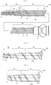
- FIG. 4 is an overall view of a dilator 30 according to a fourth embodiment of the present invention.
- the left side of the drawing is the distal end side (distal side) inserted into the body, and the right side is the proximal end side (proximal side) operated by an operator such as a physician.
- the dilator 30 comprises a shaft 31, a spirally-arranged protruding portion 32, and a connector 9 that is connected to the proximal end of the shaft 31.
- the shaft 31 has a hollow shape and is formed having a lumen 31A that passes through from the distal end to the proximal end. Furthermore, the shaft 31 includes a body portion 33, a tapered part 34, and a distal end part 35.
- the material forming the shaft 31 and the spirally-arranged protruding portion 32 is not particularly limited as long as it ensures the softness of the tapered part 34 and the distal end part 35 and is biocompatible, and examples include stainless steel, superelastic alloys such as nickel-titanium alloy, and synthetic resins such as polyvinyl chloride resins, urethane resins, polyolefin resins, polyamide resins, and fluorine resins.
- the body portion 33 is located on the proximal end side of the dilator 30, and a connector 9 is connected to the proximal end thereof. Furthermore, the body portion 33 has a substantially constant outer diameter from the proximal end to the distal end.
- the tapered part 34 is connected to the distal end of the body portion 33, extends from the distal end toward the distal end side, and has a shape which is tapered toward the distal end side. That is to say, the tapered part 34 is configured such that the outer shape at the distal end side is smaller than the outer shape at the proximal end side.
- the distal end part 35 is connected to the distal end of the tapered part 34, and extends from the distal end toward the distal end side.
- the distal end part 35 has a substantially constant outer diameter from the proximal end to the distal end.
- the shaft 31 has a hollow shape in which the outer diameter of the distal end is smaller than the outer diameter at the proximal end.
- a spirally-arranged protruding portion 32 is provided on the outer peripheral face 31B of the shaft 31 so as to protrude toward the exterior (from the outermost surface and outermost part of the dilator 30).
- the spirally-arranged protruding portion 32 is provided on a distal end side section of the body portion 33, the tapered part 34, and the distal end part 35, and has gaps in sections that are neighboring along an axis A of the shaft 31. That is to say, sections of the spirally-arranged protruding portion 32 that are neighboring are mutually separated.
- the spirally-arranged protruding portion 32 is integrally formed with the shaft 31 by casting or the like.
- the spirally-arranged protruding portion 32 is configured such that the angle of inclination with respect to the axis A of the shaft 31 gradually increases from the body portion 33 through the tapered part 34 to the distal end part 35.
- ⁇ 8 to ⁇ 11 in FIG. 4 are set such that ⁇ 11 > ⁇ 10 > ⁇ 9 > ⁇ 8. That is to say, along the axis A, the angle of inclination at the second location P6 is larger than the angle of inclination at the first location P5.
- the second location P6 is located further to the distal end side than the first location P5 and has a smaller outer diameter than the outer diameter at the first location P5.
- a spirally-arranged protruding portion 32 that protrudes toward the exterior is provided on the outer peripheral face 31B of shaft 31, and the spirally-arranged protruding portion 32 has gaps in sections that are neighboring along the axis A of the shaft 31.
- This configuration not only enables the dilator to be moved forward in a conventional fashion by a pressing operation, but also to be moved forward by a rotation operation as a result of the spirally-arranged protruding portion 32.
- the spirally-arranged protruding portion 32 of the dilator 30 of the present embodiment is formed so that, along the axis A, the angle of inclination at the second location P6 is larger than the angle of inclination at the first location P5.
- the second location P6 is located further to the distal end side than the first location P5 and has a smaller outer diameter than the outer diameter at the first location P5. Therefore, the angle of inclination of the spirally-arranged protruding portion 32 becomes larger in sections where the outer diameter of shaft 31 is relatively smaller.
- the spirally-arranged protruding portion 32 firmly catches the target object (for example, a digestive tract such as the stomach, or the liver). Consequently, spinning of the dilator 30 can be suppressed at sections where the outer diameter of the shaft 31 is relatively smaller.
- the shaft 31 has the tapered part 34 on a section on the distal end side, the penetration-hole can be smoothly expanded, and further, because the angle of inclination of the spirally-arranged protruding portion 32 is larger at the section of the shaft 31 where the outer diameter is relatively smaller, the spirally-arranged protruding portion 32 firmly catches the target object (for example, a digestive tract such as the stomach, or the liver), and spinning of the dilator 30 can be inhibited.
- the target object for example, a digestive tract such as the stomach, or the liver
- FIG. 5 is a diagram showing a distal end side section of a dilator 40 according to a fifth embodiment.
- the left side of the drawing is the distal end side (far side) inserted into the body, and the right side is the proximal end side (near side) operated by an operator such as a physician.
- the dilator 40 comprises a shaft 41, a spirally-arranged protruding portion 42, and a connector 9 that is connected to the proximal end of the shaft 41 (see FIG. 4 ).
- the materials forming the shaft 41 and the spirally-arranged protruding portion 42 are the same as the materials forming the shaft 31 and the spirally-arranged protruding portion 32 of the dilator 30 of the fourth embodiment.
- the shaft 41 has a hollow shape and is formed having a lumen 41A that passes through from the distal end to the proximal end. Furthermore, the shaft 41 includes a body portion 43 and a tapered part 44.
- the dilator 40 of the present embodiment differs from the dilator 30 of the fourth embodiment in that it does not have a distal end part.
- a spirally-arranged protruding portion 42 is provided on the outer peripheral face 41B of the shaft 41 so as to protrude toward the exterior (from the outermost surface and outermost part of the dilator 40).
- the spirally-arranged protruding portion 42 is provided on a distal end side section of the body portion 43, and tapered part 44, and has gaps in sections that are neighboring along an axis A of the shaft 41. That is to say, sections of the spirally-arranged protruding portion 42 that are neighboring are mutually separated.
- the spirally-arranged protruding portion 42 is integrally formed with the shaft 41 by casting or the like.
- the spirally-arranged protruding portion 42 is configured such that the angle of inclination with respect to the axis A of the shaft 41 gradually increases from the body portion 43 to the tapered part 44.
- ⁇ 12 to ⁇ 14 in FIG. 5 are set such that ⁇ 14 > ⁇ 13 > ⁇ 12. That is to say, along the axis A, the angle of inclination at the second location P8 is larger than the angle of inclination at the first location P7.
- the second location P8 is located further to the distal end side than the first location P7 and has a smaller outer diameter than the outer diameter at the first location P7.
- a spirally-arranged protruding portion 42 that protrudes toward the exterior is provided on the outer peripheral face 41B of shaft 41, and the spirally-arranged protruding portion 42 has gaps in sections that are neighboring along the axis A of the shaft 41.
- the spirally-arranged protruding portion 42 of the dilator 40 of the present embodiment is formed so that, along the axis A, the angle of inclination at the second location P8 is larger than the angle of inclination at the first location P7.
- the second location P8 is located further to the distal end side than the first location P7 and has a smaller outer diameter than the outer diameter at the first location P7. Therefore, the angle of inclination of the spirally-arranged protruding portion becomes larger in sections where the outer diameter of shaft 41 is relatively smaller.
- the spirally-arranged protruding portion 42 firmly catches the target object (for example, a digestive tract such as the stomach, or the liver). Consequently, spinning of the dilator 40 can be suppressed at sections where the outer diameter of the shaft 41 is relatively smaller.
- the shaft 41 has the tapered part 44 on a section on the distal end side, the penetration-hole can be smoothly expanded, and further, because the angle of inclination of the spirally-arranged protruding portion 42 is larger at the section of the shaft 41 where the outer diameter is relatively smaller, the spirally-arranged protruding portion 42 firmly catches the target object (for example, a digestive tract such as the stomach, or the liver), and spinning of the dilator 40 can be inhibited.
- the target object for example, a digestive tract such as the stomach, or the liver
- FIG. 6 is a diagram showing a distal end side section of a dilator 50 according to a sixth embodiment.
- the left side of the drawing is the distal end side (distal side) inserted into the body, and the right side is the proximal end side (proximal side) operated by an operator such as a physician.
- the dilator 50 comprises a shaft 51, a spirally-arranged protruding portion 52, and a connector 9 that is connected to the proximal end of the shaft 51 (see FIG. 4 ).
- the materials forming the shaft 51 and the spirally-arranged protruding portion 52 are the same as the materials forming the shaft 31 and the spirally-arranged protruding portion 32 of the dilator 30 of the fourth embodiment.
- the shaft 51 has a hollow shape and is formed having a lumen 51A that passes through from the distal end to the proximal end. Furthermore, the shaft 51 includes a tapered part 54.
- the dilator 50 of the present embodiment differs from the dilator 30 of the fourth embodiment in that it does not have a distal end part and a body portion. That is to say, the shaft 51 has a tapered shape in which the outer diameter gradually decreases over the full length from the proximal end to the distal end. Therefore, the shaft 51 has a hollow shape in which the outer diameter of the distal end is smaller than the outer diameter of the proximal end.
- a spirally-arranged protruding portion 52 is provided on the outer peripheral face 51B of the shaft 51 so as to protrude toward the exterior (from the outermost surface and outermost part of the dilator 50).
- the spirally-arranged protruding portion 52 is provided on a distal end side section of the tapered part 54 and has gaps in sections that are neighboring along an axis A of the shaft 51. That is to say, sections of the spirally-arranged protruding portion 52 that are neighboring are mutually separated.
- the spirally-arranged protruding portion 52 is integrally formed with the shaft 51 by casting or the like.
- the spirally-arranged protruding portion 52 is configured such that the angle of inclination with respect to the axis A of the shaft 51 gradually increases from the proximal end side to the distal end side of the tapered part 54.
- ⁇ 15 to ⁇ 17 in FIG. 6 are set such that ⁇ 17 > ⁇ 16 > ⁇ 15. That is to say, along the axis A, the angle of inclination at the second location P10 is larger than the angle of inclination at the first location P9.
- the second location P10 is located further to the distal end side than the first location P9 and has a smaller outer diameter than the outer diameter at the first location P9.
- a spirally-arranged protruding portion 52 that protrudes toward the exterior is provided on the outer peripheral face 51B of shaft 51, and the spirally-arranged protruding portion 52 has gaps in sections that are neighboring along the axis A of the shaft 51.
- the spirally-arranged protruding portion 52 of the dilator 50 of the present embodiment is formed so that, along the axis A, the angle of inclination at the second location P10 is larger than the angle of inclination at the first location P9.
- the second location P10 is located further to the distal end side than the first location P9 and has a smaller outer diameter than the outer diameter at the first location P9. Therefore, the angle of inclination of the spirally-arranged protruding portion becomes larger in sections where the outer diameter of shaft 51 is relatively smaller.
- the spirally-arranged protruding portion 42 firmly catches the target object (for example, a digestive tract such as the stomach, or the liver). Consequently, spinning of the dilator 50 can be suppressed at sections where the outer diameter of the shaft 51 is relatively smaller.
- the shaft 51 has the tapered part 54, the penetration-hole can be smoothly expanded, and further, because the angle of inclination of the spirally-arranged protruding portion 52 is larger at the section of the shaft 51 where the outer diameter is relatively smaller, the spirally-arranged protruding portion 52 firmly catches the target object (for example, a digestive tract such as the stomach, or the liver), and spinning of the dilator 50 can be inhibited.
- the target object for example, a digestive tract such as the stomach, or the liver
- the dilator 1 of the first embodiment may be a dilator 100 in which the second coil 5 has gaps in sections that are neighboring along the axial direction of the first coil 3 up to the proximal end thereof.
- a dilator 1 was described in which the shaft and the spirally-arranged protruding portion are both constituted by a coil
- dilators 30, 40, and 50 were described in which the shafts 31, 41, and 51 and the spirally-arranged protruding portions 32, 42, and 52 are integrally formed by casting or the like.
- the dilator may be formed such that, like the shafts 31, 41, and 51, only the shaft is formed by casting, and the spirally-arranged protruding portion is constituted by a coil.
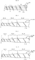
- the dilator may also be a dilator 300 configured by a shaft 31 and a spirally-arranged protruding portion (second coil 5) as shown in FIG. 8 , a dilator 400 configured by a shaft 41 and a spirally-arranged protruding portion (second coil 5) as shown in FIG. 9 , or a dilator 500 configured by a shaft 51 and a spirally-arranged protruding portion (second coil 5) as shown in FIG. 10 .
- a dilator 300 configured by a shaft 31 and a spirally-arranged protruding portion (second coil 5) as shown in FIG. 8
- a dilator 400 configured by a shaft 41 and a spirally-arranged protruding portion (second coil 5) as shown in FIG. 9
- a dilator 500 configured by a shaft 51 and a spirally-arranged protruding portion (second coil 5) as shown in FIG. 10 .
- sections of the second coil 5 which are mutually separated along the axis A are configured so that the angle of inclination with respect to the axis A of the shafts 31, 41, and 51 gradually increases from the proximal end side to the distal end side. That is to say, x, y, and z in FIG. 8 to FIG. 10 are set so that x>y>z.
- the angle of inclination at the second location which is located further to the distal end side than the first location and has a smaller outer diameter than the outer diameter of the first location, is configured to be larger than the angle of inclination at the first location along the axis A.
- the second coil 5 and the spirally-arranged protruding portion 32 are configured so that the angle of inclination with respect to the axis A of the first coil 3 and the shaft 31 gradually increases from the body portions 3C and 33 through the tapered parts 3D and 34 to the distal end parts 3E and 35. That is to say, ⁇ , ⁇ , and ⁇ in FIG. 11 are configured so that ⁇ > ⁇ > ⁇ .
- ⁇ is the angle of inclination of the second coil 5 and the spirally-arranged protruding portion 32 with respect to the axis A at the distal end parts 3E and 35
- ⁇ is the angle of inclination of the second coil 5 and the spirally-arranged protruding portion 32 with respect to the axis A at the tapered parts 3D and 34
- ⁇ is the angle of inclination of the second coil 5 and the spirally-arranged protruding portion 32 with respect to the axis A at the body portions 3C and 33.
- dilators 1D, 30D, and 300D where ⁇ , and ⁇ > ⁇ (see FIG. 15 ) are also possible.
- the dilators 1A, 1B, 1C, and 1D are modifications of the dilator 1 where the shaft and the spirally-arranged protruding portion are both configured by a coil in a similar fashion to the dilator 1 of FIG. 1
- the dilators 30A, 30B, 30C, and 30D are modifications of the dilator 30 where the shaft and the spirally-arranged protruding portion are both integrally formed by casting or the like in a similar fashion to the dilator 30 of FIG.
- the dilators 300A, 300B, 300C, and 300D are modifications of the dilator 300 where the shaft is formed by casting or the like, and the spirally-arranged protruding portion is configured by a coil in a similar fashion to the dilator 300 of FIG. 8 .
- the spirally-arranged protruding portion may be provided up to the proximal end of the shaft.
- the second coil provided on the outer circumference of the shaft may or may not have gaps in sections that are neighboring along the axis of the shaft up to the proximal end thereof.
- first coils 3 and 21 were described as hollow coil bodies formed from ten wires, the number of wires is not limited to ten, and may be one or more.
- the coil body 22 was described as a coil body formed from sixteen wires, the number of wires is not limited to sixteen, and may be one or more.
- the coil body 23 was described as a coil body formed from 23 wires, the number of wires is not limited to 23, and may be one or more.
- tip 6 of the second embodiment is formed by pouring a brazing material into the distal end of the multilayered body 17
- a tip 6 having a flat surface may be formed by polishing the second coil 5 near the distal end part of the multilayered body 17 and/or the outer circumference of the first coil 3.
- the tip 6 of the second embodiment is fixed to the distal end of the multilayered body 17, the tip may be fixed to the distal end of the multilayered body 27 of the third embodiment, the distal end of the shaft 31 of the fourth embodiment, the distal end of the shaft 41 of the fifth embodiment, and the distal end of the shaft 51 of the sixth embodiment.
- the multilayered bodies 7, 17, and 27 of the first to third embodiments, and the shafts 31, 41, and 51 and the spirally-arranged protruding portions 32, 42, and 52 of the fourth to sixth embodiments may have the outer circumference coated with a resin.
- the outer circumference of the dilator 30, the shaft 31 and the spirally-arranged protruding portion 32 of the fourth embodiment may be coated with a resin 36.
- the resin 36 can improve the slidability.
- the shaft is constituted by the first coil 3
- the outer circumference of the shaft 31 is coated by the resin 36
- the sections of the body portion 33, the tapered part 34, and the distal end part 35 that are coated by the resin 36 correspond to the shaft 31, and the sections that protrude toward the exterior from the outer peripheral face 31B of the shaft 31 correspond to the spirally-arranged protruding portion 32.
- the resin 36 examples include biocompatible resin materials such as polyamide resins and fluororesins, and hydrophilic coating materials, and the thickness thereof is, for example, 0.1 to 300 pm.
- biocompatible resin materials such as polyamide resins and fluororesins, and hydrophilic coating materials, and the thickness thereof is, for example, 0.1 to 300 pm.
- the shafts 31, 41, and 51 were integrally formed with the spirally-arranged protruding portions 32, 42, and 52, these may be separately formed.
- the second coils 5, 24, and 25 and the spirally-arranged protruding portions 32, 42, and 52 were configured such that the angle of inclination gradually decreased, a configuration in which the angle of inclination decreases in a stepwise fashion is also possible.
- the shafts 31, 41, and 51 were integrally formed with the spirally-arranged protruding portions 32, 42, and 52, these may be separately formed.
- first locations P1, P3, P5, P7, and P9 and the second locations P2, P4, P6, P8, and P10 are not limited to the positions described in the embodiments above, and the first location and the second location may be located anywhere that satisfies the relationship that the second location is located further to the distal end side than the first location, and has a smaller outer diameter than the outer diameter at the first location.
- the shaft may have various coatings on the surface side (including parts between the shaft and the spirally-arranged protruding portion).
- the coating include a protective film (a typical example being a plating film) on the surface of the shaft, and a base film for improving the adhesion between the shaft and the spirally-arranged protruding portion.
- the spirally-arranged protruding portion preferably does not constitute a blade.
- the dilators of the present embodiments expand a pre-formed penetration-hole in a target object (an example being the wall of a digestive tract such as a patient's stomach). Therefore, if the spirally-arranged protruding portion constitutes a blade, the living tissue on the inner surface of the penetration-hole may become damaged.
- the cross-sectional shape of the spirally-arranged protruding portion (for example, the shape of a cross-section taken orthogonally to the helix direction of the spirally-arranged protruding portion shown in FIG. 4 ) preferably does not include a corner portion having an acute angle on the radially outer end part of the shaft. That is to say, the end part preferably has a part which is formed having, for example, a shape including a corner portion having an obtuse angle, or a curve (for example, a curve containing part of a circle or an ellipse).
Landscapes
- Health & Medical Sciences (AREA)
- Life Sciences & Earth Sciences (AREA)
- Veterinary Medicine (AREA)
- Public Health (AREA)
- Engineering & Computer Science (AREA)
- Biomedical Technology (AREA)
- Heart & Thoracic Surgery (AREA)
- Animal Behavior & Ethology (AREA)
- General Health & Medical Sciences (AREA)
- Anesthesiology (AREA)
- Hematology (AREA)
- Surgery (AREA)
- Pulmonology (AREA)
- Biophysics (AREA)
- Pathology (AREA)
- Nuclear Medicine, Radiotherapy & Molecular Imaging (AREA)
- Medical Informatics (AREA)
- Molecular Biology (AREA)
- Dermatology (AREA)
- Oral & Maxillofacial Surgery (AREA)
- Media Introduction/Drainage Providing Device (AREA)
- Surgical Instruments (AREA)
- Prostheses (AREA)
- Gasket Seals (AREA)
Applications Claiming Priority (3)
| Application Number | Priority Date | Filing Date | Title |
|---|---|---|---|
| JP2017012024 | 2017-03-24 | ||
| PCT/JP2018/011672 WO2018174241A1 (fr) | 2017-03-24 | 2018-03-23 | Dilatateur |
| PCT/JP2018/035088 WO2019181011A1 (fr) | 2017-03-24 | 2018-09-21 | Dilatateur |
Publications (3)
| Publication Number | Publication Date |
|---|---|
| EP3769703A1 true EP3769703A1 (fr) | 2021-01-27 |
| EP3769703A4 EP3769703A4 (fr) | 2021-12-01 |
| EP3769703B1 EP3769703B1 (fr) | 2023-07-12 |
Family
ID=63585555
Family Applications (6)
| Application Number | Title | Priority Date | Filing Date |
|---|---|---|---|
| EP18771917.4A Withdrawn EP3603549A4 (fr) | 2017-03-24 | 2018-03-23 | Dilatateur |
| EP18772158.4A Active EP3603550B1 (fr) | 2017-03-24 | 2018-03-23 | Dilatateur |
| EP18772596.5A Active EP3603551B1 (fr) | 2017-03-24 | 2018-03-23 | Dilatateur |
| EP18771309.4A Active EP3603548B1 (fr) | 2017-03-24 | 2018-03-23 | Dilatateur |
| EP18910592.7A Active EP3769702B1 (fr) | 2017-03-24 | 2018-09-21 | Dilatateur |
| EP18910960.6A Active EP3769703B1 (fr) | 2017-03-24 | 2018-09-21 | Dilatateur |
Family Applications Before (5)
| Application Number | Title | Priority Date | Filing Date |
|---|---|---|---|
| EP18771917.4A Withdrawn EP3603549A4 (fr) | 2017-03-24 | 2018-03-23 | Dilatateur |
| EP18772158.4A Active EP3603550B1 (fr) | 2017-03-24 | 2018-03-23 | Dilatateur |
| EP18772596.5A Active EP3603551B1 (fr) | 2017-03-24 | 2018-03-23 | Dilatateur |
| EP18771309.4A Active EP3603548B1 (fr) | 2017-03-24 | 2018-03-23 | Dilatateur |
| EP18910592.7A Active EP3769702B1 (fr) | 2017-03-24 | 2018-09-21 | Dilatateur |
Country Status (6)
| Country | Link |
|---|---|
| US (7) | US20200016387A1 (fr) |
| EP (6) | EP3603549A4 (fr) |
| JP (10) | JP6588678B2 (fr) |
| KR (4) | KR102305196B1 (fr) |
| CN (6) | CN110290755B (fr) |
| WO (6) | WO2018174243A1 (fr) |
Families Citing this family (15)
| Publication number | Priority date | Publication date | Assignee | Title |
|---|---|---|---|---|
| EP3603549A4 (fr) * | 2017-03-24 | 2020-11-11 | Asahi Intecc Co., Ltd. | Dilatateur |
| EP3791916A4 (fr) * | 2018-05-09 | 2021-12-15 | Asahi Intecc Co., Ltd. | Tube à usage médical |
| JP7457579B2 (ja) * | 2020-06-01 | 2024-03-28 | 朝日インテック株式会社 | ダイレータ |
| WO2021255906A1 (fr) * | 2020-06-18 | 2021-12-23 | 朝日インテック株式会社 | Dispositif de maintien |
| US11471651B2 (en) * | 2020-06-22 | 2022-10-18 | Medtronic, Inc. | Balloon catheter including a guidewire tube with a friction-increasing outer coating |
| CN111743619A (zh) * | 2020-08-06 | 2020-10-09 | 北京大学第三医院(北京大学第三临床医学院) | 一种扩张切开装置 |
| EP4209187B1 (fr) * | 2020-09-03 | 2025-04-16 | Asahi Intecc Co., Ltd. | Dilatateur |
| CN114588474A (zh) * | 2020-12-04 | 2022-06-07 | 巴德阿克塞斯系统股份有限公司 | 配置为进入皮肤插入部位的导管的远侧区段 |
| WO2023112192A1 (fr) * | 2021-12-15 | 2023-06-22 | 朝日インテック株式会社 | Dilatateur |
| JP2024104068A (ja) * | 2023-01-23 | 2024-08-02 | 朝日インテック株式会社 | 医療デバイス |
| JP2024108422A (ja) * | 2023-01-31 | 2024-08-13 | 朝日インテック株式会社 | 医療デバイス |
| USD1095831S1 (en) | 2023-04-07 | 2025-09-30 | Asahi Intecc Co., Ltd. | Medical dilator |
| EP4719571A2 (fr) * | 2023-05-25 | 2026-04-08 | Terumo Corporation | Dispositif vasculaire à friction multiple |
| WO2025052857A1 (fr) * | 2023-09-07 | 2025-03-13 | 株式会社カネカ | Aiguille de ponction ainsi que cathéter de ponction comportant ladite aiguille de ponction |
| JP2025104540A (ja) * | 2023-12-28 | 2025-07-10 | 国立研究開発法人理化学研究所 | 原子トラップ装置、原子冷却装置、分光装置、光格子時計、量子コンピュータ、コイル、原子トラップ方法、原子冷却方法および分光方法 |
Family Cites Families (79)
| Publication number | Priority date | Publication date | Assignee | Title |
|---|---|---|---|---|
| US207932A (en) * | 1878-09-10 | Improvement in surgical dilators | ||
| JPS60234671A (ja) | 1984-05-09 | 1985-11-21 | テルモ株式会社 | カテ−テル導入具 |
| DE3532653C2 (de) * | 1985-09-13 | 1993-10-21 | Martin Kaltenbach | Dilatationskatheter |
| DK163713C (da) | 1987-09-02 | 1992-09-07 | Ole Gyring Nieben | Anordning til anbringelse af et partielt kateter i et legemshulrum |
| AU6752090A (en) * | 1989-11-16 | 1991-06-13 | Kensey Nash Corporation | A percutaneous transtracheal airway device and procedure |
| US5211636A (en) * | 1990-10-31 | 1993-05-18 | Lake Region Manufacturing Co., Inc. | Steerable infusion guide wire |
| EP0556316B1 (fr) | 1990-11-09 | 1997-01-22 | Boston Scientific Corporation | Fil de guidage destine a traverser des occlusions dans des vaisseaux sanguins |
| JP2502565Y2 (ja) * | 1990-12-18 | 1996-06-26 | 株式会社パイオラックス | 医療用ガイドワイヤ |
| US5409470A (en) * | 1993-05-07 | 1995-04-25 | C. R. Bard, Inc. | Dilatation catheter and guidewire with threaded tip connection |
| US5630813A (en) * | 1994-12-08 | 1997-05-20 | Kieturakis; Maciej J. | Electro-cauterizing dissector and method for facilitating breast implant procedure |
| US20030069522A1 (en) * | 1995-12-07 | 2003-04-10 | Jacobsen Stephen J. | Slotted medical device |
| DE19636318A1 (de) * | 1996-08-29 | 1998-03-05 | Knigge Ursel | Obturator |
| JP4015298B2 (ja) | 1998-07-31 | 2007-11-28 | 三洲電線株式会社 | 多層中空圧縮撚線の製造方法 |
| US6508804B2 (en) * | 1999-07-28 | 2003-01-21 | Scimed Life Systems, Inc. | Catheter having continuous lattice and coil reinforcement |
| JP3858560B2 (ja) | 2000-03-31 | 2006-12-13 | フジノン株式会社 | コイルシャフトの製造方法 |
| ES2250285T3 (es) * | 2000-11-03 | 2006-04-16 | Willy Rusch Gmbh | Dilatador para traqueotomia. |
| US9192410B2 (en) | 2001-03-14 | 2015-11-24 | Covidien Lp | Trocar device |
| WO2003043685A2 (fr) * | 2001-11-19 | 2003-05-30 | Cardiovascular Systems, Inc | Systeme de fil guide intravasculaire discret a couple eleve |
| US20050165405A1 (en) * | 2001-11-30 | 2005-07-28 | Tsou Paul M. | Minimal access apparatus for endoscopic spinal surgery |
| JP2004009844A (ja) | 2002-06-05 | 2004-01-15 | Shuji Tarumoto | ギヤードケーブル |
| EP1526815A1 (fr) * | 2002-07-31 | 2005-05-04 | MicroVention, Inc. | Dispositif d'occlusion vasculaire a trois elements coaxiaux |
| US6887194B2 (en) | 2003-01-17 | 2005-05-03 | Applied Medical Resources Corporation | Surgical access apparatus and method |
| WO2005012866A2 (fr) | 2003-07-30 | 2005-02-10 | Bbnt Solutions Llc | Mesure de la compaction du sol sur une plateforme amovible |
| US7811303B2 (en) * | 2003-08-26 | 2010-10-12 | Medicine Lodge Inc | Bodily tissue dilation systems and methods |
| JP2005118102A (ja) | 2003-10-14 | 2005-05-12 | Pentax Corp | 内視鏡用スネア |
| JP4497454B2 (ja) * | 2004-04-06 | 2010-07-07 | 朝日インテック株式会社 | 医療用具 |
| JP2006130073A (ja) | 2004-11-05 | 2006-05-25 | Olympus Corp | 超音波トロッカー |
| JP4804780B2 (ja) * | 2005-03-28 | 2011-11-02 | テルモ株式会社 | 生体器官拡張器具 |
| US8414477B2 (en) | 2005-05-04 | 2013-04-09 | Olympus Endo Technology America Inc. | Rotate-to-advance catheterization system |
| US20070088230A1 (en) * | 2005-09-06 | 2007-04-19 | Fmd Co., Ltd | Medical instrument and medical equipment for treatment, and rotational handle device |
| JP2007098120A (ja) * | 2005-09-06 | 2007-04-19 | Fmd:Kk | 医療用処置具及びその回転操作装置並びに医療用処置装置 |
| US8500628B2 (en) * | 2006-02-28 | 2013-08-06 | Olympus Endo Technology America, Inc. | Rotate-to-advance catheterization system |
| US20090281500A1 (en) * | 2006-04-19 | 2009-11-12 | Acosta Pablo G | Devices, system and methods for minimally invasive abdominal surgical procedures |
| JP2008011867A (ja) | 2006-05-25 | 2008-01-24 | Nippon Zeon Co Ltd | ダイレーター、ダイレーターの製造方法、およびシースイントロデューサー |
| US8419658B2 (en) * | 2006-09-06 | 2013-04-16 | Boston Scientific Scimed, Inc. | Medical device including structure for crossing an occlusion in a vessel |
| US8043343B2 (en) * | 2007-06-28 | 2011-10-25 | Zimmer Spine, Inc. | Stabilization system and method |
| US9597172B2 (en) * | 2007-09-28 | 2017-03-21 | W. L. Gore & Associates, Inc. | Retrieval catheter |
| US8795326B2 (en) * | 2007-10-05 | 2014-08-05 | Covidien Lp | Expanding seal anchor for single incision surgery |
| WO2010078196A1 (fr) | 2008-12-31 | 2010-07-08 | St. Jude Medical, Atrial Fibrillation Division, Inc. | Aiguille transseptale à action rapide ou rotative |
| US8764727B2 (en) * | 2009-03-06 | 2014-07-01 | Cook Medical Technologies Llc | Reinforced rapid exchange catheter |
| US8343035B2 (en) * | 2009-04-20 | 2013-01-01 | Spine View, Inc. | Dilator with direct visualization |
| JP4863321B2 (ja) * | 2009-06-16 | 2012-01-25 | 朝日インテック株式会社 | 医療用ガイドワイヤ |
| US20110022026A1 (en) * | 2009-07-21 | 2011-01-27 | Lake Region Manufacturing, Inc. d/b/a Lake Region Medical. Inc. | Methods and Devices for Delivering Drugs Using Drug-Delivery or Drug-Coated Guidewires |
| US20110082338A1 (en) * | 2009-10-01 | 2011-04-07 | Tyco Healthcare Group Lp | Port fixation with varying thread pitch |
| US9339599B2 (en) * | 2009-12-21 | 2016-05-17 | Sorin Group Usa, Inc. | Self-dilating cannula |
| US20130012955A1 (en) * | 2010-03-17 | 2013-01-10 | Dean Lin | System and Method for Pedicle Screw Placement in Vertebral Alignment |
| US20120116350A1 (en) * | 2010-07-07 | 2012-05-10 | Reverse Medical Corporation | Translation dilator and stand alone vascular guide catheter |
| JP2012095812A (ja) * | 2010-11-01 | 2012-05-24 | Olympus Corp | 医療用デバイス |
| JP5736735B2 (ja) * | 2010-11-09 | 2015-06-17 | 住友ベークライト株式会社 | カテーテル |
| JP5448200B2 (ja) | 2011-03-01 | 2014-03-19 | 朝日インテック株式会社 | ガイドワイヤ |
| JP5582612B2 (ja) | 2011-03-03 | 2014-09-03 | 朝日インテック株式会社 | 体内回収機構用ロープ |
| JP5424499B2 (ja) * | 2011-04-18 | 2014-02-26 | 朝日インテック株式会社 | 医療用ガイドワイヤ |
| JP5392792B2 (ja) * | 2011-06-06 | 2014-01-22 | 朝日インテック株式会社 | ガイドワイヤ |
| EP2740512B1 (fr) * | 2011-08-01 | 2016-10-12 | Terumo Kabushiki Kaisha | Dilatateur, ensemble introducteur, et outil médical |
| CN103717252B (zh) * | 2011-08-01 | 2016-10-26 | 泰尔茂株式会社 | 扩张器 |
| AU2012315597B2 (en) * | 2011-09-30 | 2016-01-07 | Bioventrix, Inc. | Trans-catheter ventricular reconstruction structures, methods, and systems for treatment of congestive heart failure and other conditions |
| KR20140087032A (ko) * | 2011-10-31 | 2014-07-08 | 유타카 스즈키 | 의료용 확장기 및 의료용 확장기 세트 |
| US9107693B2 (en) | 2012-04-16 | 2015-08-18 | Pacesetter, Inc. | Apparatus and method for pericardial access |
| JP5652884B2 (ja) | 2012-07-27 | 2015-01-14 | 朝日インテック株式会社 | ガイドワイヤ |
| US20140046357A1 (en) * | 2012-08-09 | 2014-02-13 | Cook Medical Technologies Llc | Dilation device |
| JP6066477B2 (ja) | 2013-01-17 | 2017-01-25 | 日本ライフライン株式会社 | 医療用ガイドワイヤ |
| JP5991951B2 (ja) | 2013-07-12 | 2016-09-14 | 富士フイルム株式会社 | 内視鏡用可撓管および内視鏡型医療機器 |
| CN105074306B (zh) | 2013-03-27 | 2017-03-15 | 富士胶片株式会社 | 内窥镜用挠性管及其制造方法 |
| WO2014208332A1 (fr) * | 2013-06-26 | 2014-12-31 | オリンパスメディカルシステムズ株式会社 | Unité spiralée, dispositif d'insertion, et procédé de fabrication d'unité spiralée |
| EP2842594A1 (fr) | 2013-09-03 | 2015-03-04 | Coloplast A/S | Gaine d'accès |
| US9408631B2 (en) | 2013-09-27 | 2016-08-09 | Depuy Mitek, Llc | Flexible cannula and obturator |
| US9789283B2 (en) * | 2014-02-03 | 2017-10-17 | Medinol Ltd. | Catheter tip assembled with a spring |
| JP6195382B2 (ja) * | 2014-07-02 | 2017-09-13 | 朝日インテック株式会社 | 医療用チューブ体 |
| AU2014402333A1 (en) | 2014-08-01 | 2017-02-16 | Vadovations, Inc. | Coring dilator for defining an aperture in a tissue wall |
| JP5874885B1 (ja) * | 2015-02-24 | 2016-03-02 | 株式会社エフエムディ | 医療用ガイドワイヤ |
| US20160287849A1 (en) | 2015-03-31 | 2016-10-06 | Boston Scientific Scimed, Inc. | Vibrating self-dilation bougie |
| JP6540956B2 (ja) | 2015-09-08 | 2019-07-10 | 日本ゼオン株式会社 | 超音波内視鏡用ダイレータ |
| CN205322443U (zh) * | 2015-12-04 | 2016-06-22 | 浙江申达斯奥医疗器械有限公司 | 一种微创胸腔手术的穿刺器 |
| EP3184237B1 (fr) | 2015-12-22 | 2020-05-27 | Sandvik Intellectual Property AB | Module capteur et porte-outil pour un outil de coupe |
| US20170296221A1 (en) | 2016-04-18 | 2017-10-19 | QXMedical, LLC. | Catheter for Advancing Through a Vascular Stenosis and Related Methods |
| EP3603549A4 (fr) | 2017-03-24 | 2020-11-11 | Asahi Intecc Co., Ltd. | Dilatateur |
| WO2018180209A1 (fr) | 2017-03-28 | 2018-10-04 | テルモ株式会社 | Dispositif médical |
| JP6868319B2 (ja) | 2017-10-25 | 2021-05-12 | 朝日インテック株式会社 | カテーテル |
| EP3476423B1 (fr) * | 2017-10-27 | 2021-01-20 | Heraeus Medical Components, LLC | Microcathéter et procédé |
-
2018
- 2018-03-23 EP EP18771917.4A patent/EP3603549A4/fr not_active Withdrawn
- 2018-03-23 EP EP18772158.4A patent/EP3603550B1/fr active Active
- 2018-03-23 KR KR1020197030762A patent/KR102305196B1/ko active Active
- 2018-03-23 KR KR1020197030763A patent/KR20190127876A/ko not_active Ceased
- 2018-03-23 CN CN201880010385.6A patent/CN110290755B/zh active Active
- 2018-03-23 WO PCT/JP2018/011674 patent/WO2018174243A1/fr not_active Ceased
- 2018-03-23 EP EP18772596.5A patent/EP3603551B1/fr active Active
- 2018-03-23 CN CN201880019242.1A patent/CN110461258A/zh not_active Withdrawn
- 2018-03-23 WO PCT/JP2018/011671 patent/WO2018174240A1/fr not_active Ceased
- 2018-03-23 CN CN201880005761.2A patent/CN110139616B/zh active Active
- 2018-03-23 WO PCT/JP2018/011672 patent/WO2018174241A1/fr not_active Ceased
- 2018-03-23 KR KR1020197021623A patent/KR102299776B1/ko active Active
- 2018-03-23 JP JP2019507021A patent/JP6588678B2/ja active Active
- 2018-03-23 JP JP2019507020A patent/JP6588677B2/ja active Active
- 2018-03-23 CN CN201880019247.4A patent/CN110520070B/zh active Active
- 2018-03-23 EP EP18771309.4A patent/EP3603548B1/fr active Active
- 2018-03-23 WO PCT/JP2018/011673 patent/WO2018174242A1/fr not_active Ceased
- 2018-03-23 KR KR1020197030761A patent/KR102305195B1/ko active Active
- 2018-03-23 JP JP2018530811A patent/JP6445745B1/ja active Active
- 2018-03-23 JP JP2019507019A patent/JP6588676B2/ja active Active
- 2018-06-15 JP JP2018114163A patent/JP2018167050A/ja active Pending
- 2018-09-21 CN CN201880091432.4A patent/CN111885975A/zh active Pending
- 2018-09-21 WO PCT/JP2018/035088 patent/WO2019181011A1/fr not_active Ceased
- 2018-09-21 JP JP2020507310A patent/JP6978583B2/ja active Active
- 2018-09-21 EP EP18910592.7A patent/EP3769702B1/fr active Active
- 2018-09-21 EP EP18910960.6A patent/EP3769703B1/fr active Active
- 2018-09-21 CN CN201880091517.2A patent/CN111970982B/zh active Active
- 2018-09-21 WO PCT/JP2018/035089 patent/WO2019181012A1/fr not_active Ceased
-
2019
- 2019-09-12 JP JP2019166194A patent/JP7344059B2/ja active Active
- 2019-09-12 JP JP2019166177A patent/JP2019205933A/ja active Pending
- 2019-09-12 JP JP2019166112A patent/JP2020006209A/ja active Pending
- 2019-09-12 JP JP2019166153A patent/JP7431001B2/ja active Active
- 2019-09-24 US US16/580,437 patent/US20200016387A1/en not_active Abandoned
- 2019-09-24 US US16/580,301 patent/US11331459B2/en active Active
- 2019-09-24 US US16/579,946 patent/US11389631B2/en active Active
- 2019-09-24 US US16/579,921 patent/US20200016384A1/en not_active Abandoned
-
2020
- 2020-09-23 US US17/029,623 patent/US12453843B2/en active Active
- 2020-09-23 US US17/029,562 patent/US20210001097A1/en active Pending
-
2022
- 2022-06-02 US US17/830,621 patent/US11819647B2/en active Active
Also Published As
Similar Documents
| Publication | Publication Date | Title |
|---|---|---|
| EP3769703B1 (fr) | Dilatateur | |
| EP3854327B1 (fr) | Dilatateur | |
| JP6588679B1 (ja) | ダイレータ |
Legal Events
| Date | Code | Title | Description |
|---|---|---|---|
| STAA | Information on the status of an ep patent application or granted ep patent |
Free format text: STATUS: THE INTERNATIONAL PUBLICATION HAS BEEN MADE |
|
| PUAI | Public reference made under article 153(3) epc to a published international application that has entered the european phase |
Free format text: ORIGINAL CODE: 0009012 |
|
| STAA | Information on the status of an ep patent application or granted ep patent |
Free format text: STATUS: REQUEST FOR EXAMINATION WAS MADE |
|
| 17P | Request for examination filed |
Effective date: 20201023 |
|
| AK | Designated contracting states |
Kind code of ref document: A1 Designated state(s): AL AT BE BG CH CY CZ DE DK EE ES FI FR GB GR HR HU IE IS IT LI LT LU LV MC MK MT NL NO PL PT RO RS SE SI SK SM TR |
|
| AX | Request for extension of the european patent |
Extension state: BA ME |
|
| DAV | Request for validation of the european patent (deleted) | ||
| DAX | Request for extension of the european patent (deleted) | ||
| A4 | Supplementary search report drawn up and despatched |
Effective date: 20211103 |
|
| RIC1 | Information provided on ipc code assigned before grant |
Ipc: A61B 90/00 20160101ALI20211027BHEP Ipc: A61M 29/00 20060101ALI20211027BHEP Ipc: A61M 25/06 20060101ALI20211027BHEP Ipc: A61B 17/34 20060101AFI20211027BHEP |
|
| GRAP | Despatch of communication of intention to grant a patent |
Free format text: ORIGINAL CODE: EPIDOSNIGR1 |
|
| STAA | Information on the status of an ep patent application or granted ep patent |
Free format text: STATUS: GRANT OF PATENT IS INTENDED |
|
| RIC1 | Information provided on ipc code assigned before grant |
Ipc: A61B 90/00 20160101ALI20230220BHEP Ipc: A61M 29/00 20060101ALI20230220BHEP Ipc: A61M 25/06 20060101ALI20230220BHEP Ipc: A61B 17/34 20060101AFI20230220BHEP |
|
| INTG | Intention to grant announced |
Effective date: 20230310 |
|
| GRAS | Grant fee paid |
Free format text: ORIGINAL CODE: EPIDOSNIGR3 |
|
| GRAA | (expected) grant |
Free format text: ORIGINAL CODE: 0009210 |
|
| STAA | Information on the status of an ep patent application or granted ep patent |
Free format text: STATUS: THE PATENT HAS BEEN GRANTED |
|
| AK | Designated contracting states |
Kind code of ref document: B1 Designated state(s): AL AT BE BG CH CY CZ DE DK EE ES FI FR GB GR HR HU IE IS IT LI LT LU LV MC MK MT NL NO PL PT RO RS SE SI SK SM TR |
|
| REG | Reference to a national code |
Ref country code: CH Ref legal event code: EP |
|
| REG | Reference to a national code |
Ref country code: DE Ref legal event code: R096 Ref document number: 602018053435 Country of ref document: DE |
|
| REG | Reference to a national code |
Ref country code: IE Ref legal event code: FG4D |
|
| REG | Reference to a national code |
Ref country code: LT Ref legal event code: MG9D |
|
| REG | Reference to a national code |
Ref country code: NL Ref legal event code: MP Effective date: 20230712 |
|
| REG | Reference to a national code |
Ref country code: AT Ref legal event code: MK05 Ref document number: 1586248 Country of ref document: AT Kind code of ref document: T Effective date: 20230712 |
|
| PG25 | Lapsed in a contracting state [announced via postgrant information from national office to epo] |
Ref country code: NL Free format text: LAPSE BECAUSE OF FAILURE TO SUBMIT A TRANSLATION OF THE DESCRIPTION OR TO PAY THE FEE WITHIN THE PRESCRIBED TIME-LIMIT Effective date: 20230712 |
|
| PG25 | Lapsed in a contracting state [announced via postgrant information from national office to epo] |
Ref country code: GR Free format text: LAPSE BECAUSE OF FAILURE TO SUBMIT A TRANSLATION OF THE DESCRIPTION OR TO PAY THE FEE WITHIN THE PRESCRIBED TIME-LIMIT Effective date: 20231013 |
|
| PG25 | Lapsed in a contracting state [announced via postgrant information from national office to epo] |
Ref country code: ES Free format text: LAPSE BECAUSE OF FAILURE TO SUBMIT A TRANSLATION OF THE DESCRIPTION OR TO PAY THE FEE WITHIN THE PRESCRIBED TIME-LIMIT Effective date: 20230712 |
|
| PG25 | Lapsed in a contracting state [announced via postgrant information from national office to epo] |
Ref country code: IS Free format text: LAPSE BECAUSE OF FAILURE TO SUBMIT A TRANSLATION OF THE DESCRIPTION OR TO PAY THE FEE WITHIN THE PRESCRIBED TIME-LIMIT Effective date: 20231112 |
|
| PG25 | Lapsed in a contracting state [announced via postgrant information from national office to epo] |
Ref country code: SE Free format text: LAPSE BECAUSE OF FAILURE TO SUBMIT A TRANSLATION OF THE DESCRIPTION OR TO PAY THE FEE WITHIN THE PRESCRIBED TIME-LIMIT Effective date: 20230712 Ref country code: RS Free format text: LAPSE BECAUSE OF FAILURE TO SUBMIT A TRANSLATION OF THE DESCRIPTION OR TO PAY THE FEE WITHIN THE PRESCRIBED TIME-LIMIT Effective date: 20230712 Ref country code: PT Free format text: LAPSE BECAUSE OF FAILURE TO SUBMIT A TRANSLATION OF THE DESCRIPTION OR TO PAY THE FEE WITHIN THE PRESCRIBED TIME-LIMIT Effective date: 20231113 Ref country code: NO Free format text: LAPSE BECAUSE OF FAILURE TO SUBMIT A TRANSLATION OF THE DESCRIPTION OR TO PAY THE FEE WITHIN THE PRESCRIBED TIME-LIMIT Effective date: 20231012 Ref country code: LV Free format text: LAPSE BECAUSE OF FAILURE TO SUBMIT A TRANSLATION OF THE DESCRIPTION OR TO PAY THE FEE WITHIN THE PRESCRIBED TIME-LIMIT Effective date: 20230712 Ref country code: LT Free format text: LAPSE BECAUSE OF FAILURE TO SUBMIT A TRANSLATION OF THE DESCRIPTION OR TO PAY THE FEE WITHIN THE PRESCRIBED TIME-LIMIT Effective date: 20230712 Ref country code: IS Free format text: LAPSE BECAUSE OF FAILURE TO SUBMIT A TRANSLATION OF THE DESCRIPTION OR TO PAY THE FEE WITHIN THE PRESCRIBED TIME-LIMIT Effective date: 20231112 Ref country code: HR Free format text: LAPSE BECAUSE OF FAILURE TO SUBMIT A TRANSLATION OF THE DESCRIPTION OR TO PAY THE FEE WITHIN THE PRESCRIBED TIME-LIMIT Effective date: 20230712 Ref country code: GR Free format text: LAPSE BECAUSE OF FAILURE TO SUBMIT A TRANSLATION OF THE DESCRIPTION OR TO PAY THE FEE WITHIN THE PRESCRIBED TIME-LIMIT Effective date: 20231013 Ref country code: FI Free format text: LAPSE BECAUSE OF FAILURE TO SUBMIT A TRANSLATION OF THE DESCRIPTION OR TO PAY THE FEE WITHIN THE PRESCRIBED TIME-LIMIT Effective date: 20230712 Ref country code: ES Free format text: LAPSE BECAUSE OF FAILURE TO SUBMIT A TRANSLATION OF THE DESCRIPTION OR TO PAY THE FEE WITHIN THE PRESCRIBED TIME-LIMIT Effective date: 20230712 Ref country code: AT Free format text: LAPSE BECAUSE OF FAILURE TO SUBMIT A TRANSLATION OF THE DESCRIPTION OR TO PAY THE FEE WITHIN THE PRESCRIBED TIME-LIMIT Effective date: 20230712 |
|
| PG25 | Lapsed in a contracting state [announced via postgrant information from national office to epo] |
Ref country code: PL Free format text: LAPSE BECAUSE OF FAILURE TO SUBMIT A TRANSLATION OF THE DESCRIPTION OR TO PAY THE FEE WITHIN THE PRESCRIBED TIME-LIMIT Effective date: 20230712 |
|
| REG | Reference to a national code |
Ref country code: DE Ref legal event code: R097 Ref document number: 602018053435 Country of ref document: DE |
|
| PG25 | Lapsed in a contracting state [announced via postgrant information from national office to epo] |
Ref country code: SM Free format text: LAPSE BECAUSE OF FAILURE TO SUBMIT A TRANSLATION OF THE DESCRIPTION OR TO PAY THE FEE WITHIN THE PRESCRIBED TIME-LIMIT Effective date: 20230712 Ref country code: RO Free format text: LAPSE BECAUSE OF FAILURE TO SUBMIT A TRANSLATION OF THE DESCRIPTION OR TO PAY THE FEE WITHIN THE PRESCRIBED TIME-LIMIT Effective date: 20230712 Ref country code: EE Free format text: LAPSE BECAUSE OF FAILURE TO SUBMIT A TRANSLATION OF THE DESCRIPTION OR TO PAY THE FEE WITHIN THE PRESCRIBED TIME-LIMIT Effective date: 20230712 Ref country code: DK Free format text: LAPSE BECAUSE OF FAILURE TO SUBMIT A TRANSLATION OF THE DESCRIPTION OR TO PAY THE FEE WITHIN THE PRESCRIBED TIME-LIMIT Effective date: 20230712 Ref country code: CZ Free format text: LAPSE BECAUSE OF FAILURE TO SUBMIT A TRANSLATION OF THE DESCRIPTION OR TO PAY THE FEE WITHIN THE PRESCRIBED TIME-LIMIT Effective date: 20230712 Ref country code: SK Free format text: LAPSE BECAUSE OF FAILURE TO SUBMIT A TRANSLATION OF THE DESCRIPTION OR TO PAY THE FEE WITHIN THE PRESCRIBED TIME-LIMIT Effective date: 20230712 |
|
| REG | Reference to a national code |
Ref country code: CH Ref legal event code: PL |
|
| PG25 | Lapsed in a contracting state [announced via postgrant information from national office to epo] |
Ref country code: LU Free format text: LAPSE BECAUSE OF NON-PAYMENT OF DUE FEES Effective date: 20230921 |
|
| PLBE | No opposition filed within time limit |
Free format text: ORIGINAL CODE: 0009261 |
|
| STAA | Information on the status of an ep patent application or granted ep patent |
Free format text: STATUS: NO OPPOSITION FILED WITHIN TIME LIMIT |
|
| REG | Reference to a national code |
Ref country code: BE Ref legal event code: MM Effective date: 20230930 |
|
| PG25 | Lapsed in a contracting state [announced via postgrant information from national office to epo] |
Ref country code: LU Free format text: LAPSE BECAUSE OF NON-PAYMENT OF DUE FEES Effective date: 20230921 Ref country code: IT Free format text: LAPSE BECAUSE OF FAILURE TO SUBMIT A TRANSLATION OF THE DESCRIPTION OR TO PAY THE FEE WITHIN THE PRESCRIBED TIME-LIMIT Effective date: 20230712 Ref country code: MC Free format text: LAPSE BECAUSE OF FAILURE TO SUBMIT A TRANSLATION OF THE DESCRIPTION OR TO PAY THE FEE WITHIN THE PRESCRIBED TIME-LIMIT Effective date: 20230712 |
|
| 26N | No opposition filed |
Effective date: 20240415 |
|
| REG | Reference to a national code |
Ref country code: IE Ref legal event code: MM4A |
|
| PG25 | Lapsed in a contracting state [announced via postgrant information from national office to epo] |
Ref country code: IE Free format text: LAPSE BECAUSE OF NON-PAYMENT OF DUE FEES Effective date: 20230921 |
|
| PG25 | Lapsed in a contracting state [announced via postgrant information from national office to epo] |
Ref country code: CH Free format text: LAPSE BECAUSE OF NON-PAYMENT OF DUE FEES Effective date: 20230930 |
|
| PG25 | Lapsed in a contracting state [announced via postgrant information from national office to epo] |
Ref country code: IE Free format text: LAPSE BECAUSE OF NON-PAYMENT OF DUE FEES Effective date: 20230921 Ref country code: CH Free format text: LAPSE BECAUSE OF NON-PAYMENT OF DUE FEES Effective date: 20230930 Ref country code: SI Free format text: LAPSE BECAUSE OF FAILURE TO SUBMIT A TRANSLATION OF THE DESCRIPTION OR TO PAY THE FEE WITHIN THE PRESCRIBED TIME-LIMIT Effective date: 20230712 |
|
| PG25 | Lapsed in a contracting state [announced via postgrant information from national office to epo] |
Ref country code: BE Free format text: LAPSE BECAUSE OF NON-PAYMENT OF DUE FEES Effective date: 20230930 |
|
| PG25 | Lapsed in a contracting state [announced via postgrant information from national office to epo] |
Ref country code: BG Free format text: LAPSE BECAUSE OF FAILURE TO SUBMIT A TRANSLATION OF THE DESCRIPTION OR TO PAY THE FEE WITHIN THE PRESCRIBED TIME-LIMIT Effective date: 20230712 |
|
| PG25 | Lapsed in a contracting state [announced via postgrant information from national office to epo] |
Ref country code: BG Free format text: LAPSE BECAUSE OF FAILURE TO SUBMIT A TRANSLATION OF THE DESCRIPTION OR TO PAY THE FEE WITHIN THE PRESCRIBED TIME-LIMIT Effective date: 20230712 |
|
| PG25 | Lapsed in a contracting state [announced via postgrant information from national office to epo] |
Ref country code: CY Free format text: LAPSE BECAUSE OF FAILURE TO SUBMIT A TRANSLATION OF THE DESCRIPTION OR TO PAY THE FEE WITHIN THE PRESCRIBED TIME-LIMIT; INVALID AB INITIO Effective date: 20180921 |
|
| PG25 | Lapsed in a contracting state [announced via postgrant information from national office to epo] |
Ref country code: HU Free format text: LAPSE BECAUSE OF FAILURE TO SUBMIT A TRANSLATION OF THE DESCRIPTION OR TO PAY THE FEE WITHIN THE PRESCRIBED TIME-LIMIT; INVALID AB INITIO Effective date: 20180921 |
|
| PGFP | Annual fee paid to national office [announced via postgrant information from national office to epo] |
Ref country code: DE Payment date: 20250919 Year of fee payment: 8 |
|
| PGFP | Annual fee paid to national office [announced via postgrant information from national office to epo] |
Ref country code: GB Payment date: 20250919 Year of fee payment: 8 |
|
| PGFP | Annual fee paid to national office [announced via postgrant information from national office to epo] |
Ref country code: FR Payment date: 20250922 Year of fee payment: 8 |
|
| PG25 | Lapsed in a contracting state [announced via postgrant information from national office to epo] |
Ref country code: TR Free format text: LAPSE BECAUSE OF FAILURE TO SUBMIT A TRANSLATION OF THE DESCRIPTION OR TO PAY THE FEE WITHIN THE PRESCRIBED TIME-LIMIT Effective date: 20230712 |