EP3769904A1 - Robot de tension automatique de boulon - Google Patents
Robot de tension automatique de boulon Download PDFInfo
- Publication number
- EP3769904A1 EP3769904A1 EP19188050.9A EP19188050A EP3769904A1 EP 3769904 A1 EP3769904 A1 EP 3769904A1 EP 19188050 A EP19188050 A EP 19188050A EP 3769904 A1 EP3769904 A1 EP 3769904A1
- Authority
- EP
- European Patent Office
- Prior art keywords
- bolt
- unit
- tensioner
- existing
- connections
- Prior art date
- Legal status (The legal status is an assumption and is not a legal conclusion. Google has not performed a legal analysis and makes no representation as to the accuracy of the status listed.)
- Withdrawn
Links
Images







Classifications
-
- B—PERFORMING OPERATIONS; TRANSPORTING
- B23—MACHINE TOOLS; METAL-WORKING NOT OTHERWISE PROVIDED FOR
- B23P—METAL-WORKING NOT OTHERWISE PROVIDED FOR; COMBINED OPERATIONS; UNIVERSAL MACHINE TOOLS
- B23P19/00—Machines for simply fitting together or separating metal parts or objects, or metal and non-metal parts, whether or not involving some deformation; Tools or devices therefor so far as not provided for in other classes
- B23P19/04—Machines for simply fitting together or separating metal parts or objects, or metal and non-metal parts, whether or not involving some deformation; Tools or devices therefor so far as not provided for in other classes for assembling or disassembling parts
- B23P19/06—Screw or nut setting or loosening machines
-
- B—PERFORMING OPERATIONS; TRANSPORTING
- B23—MACHINE TOOLS; METAL-WORKING NOT OTHERWISE PROVIDED FOR
- B23P—METAL-WORKING NOT OTHERWISE PROVIDED FOR; COMBINED OPERATIONS; UNIVERSAL MACHINE TOOLS
- B23P19/00—Machines for simply fitting together or separating metal parts or objects, or metal and non-metal parts, whether or not involving some deformation; Tools or devices therefor so far as not provided for in other classes
- B23P19/04—Machines for simply fitting together or separating metal parts or objects, or metal and non-metal parts, whether or not involving some deformation; Tools or devices therefor so far as not provided for in other classes for assembling or disassembling parts
- B23P19/06—Screw or nut setting or loosening machines
- B23P19/067—Bolt tensioners
-
- B—PERFORMING OPERATIONS; TRANSPORTING
- B25—HAND TOOLS; PORTABLE POWER-DRIVEN TOOLS; MANIPULATORS
- B25B—TOOLS OR BENCH DEVICES NOT OTHERWISE PROVIDED FOR, FOR FASTENING, CONNECTING, DISENGAGING, OR HOLDING
- B25B21/00—Portable power-driven screw or nut setting or loosening tools; Attachments for drilling apparatus serving the same purpose
- B25B21/004—Portable power-driven screw or nut setting or loosening tools; Attachments for drilling apparatus serving the same purpose of the ratchet type
- B25B21/005—Portable power-driven screw or nut setting or loosening tools; Attachments for drilling apparatus serving the same purpose of the ratchet type driven by a radially acting hydraulic or pneumatic piston
-
- B—PERFORMING OPERATIONS; TRANSPORTING
- B25—HAND TOOLS; PORTABLE POWER-DRIVEN TOOLS; MANIPULATORS
- B25B—TOOLS OR BENCH DEVICES NOT OTHERWISE PROVIDED FOR, FOR FASTENING, CONNECTING, DISENGAGING, OR HOLDING
- B25B23/00—Details of, or accessories for, spanners, wrenches, screwdrivers
- B25B23/0078—Reaction arms
-
- B—PERFORMING OPERATIONS; TRANSPORTING
- B25—HAND TOOLS; PORTABLE POWER-DRIVEN TOOLS; MANIPULATORS
- B25B—TOOLS OR BENCH DEVICES NOT OTHERWISE PROVIDED FOR, FOR FASTENING, CONNECTING, DISENGAGING, OR HOLDING
- B25B29/00—Accessories
- B25B29/02—Bolt tensioners
-
- F—MECHANICAL ENGINEERING; LIGHTING; HEATING; WEAPONS; BLASTING
- F03—MACHINES OR ENGINES FOR LIQUIDS; WIND, SPRING, OR WEIGHT MOTORS; PRODUCING MECHANICAL POWER OR A REACTIVE PROPULSIVE THRUST, NOT OTHERWISE PROVIDED FOR
- F03D—WIND MOTORS
- F03D13/00—Assembly, mounting or commissioning of wind motors; Arrangements specially adapted for transporting wind motor components
- F03D13/10—Assembly of wind motors; Arrangements for erecting wind motors
-
- F—MECHANICAL ENGINEERING; LIGHTING; HEATING; WEAPONS; BLASTING
- F03—MACHINES OR ENGINES FOR LIQUIDS; WIND, SPRING, OR WEIGHT MOTORS; PRODUCING MECHANICAL POWER OR A REACTIVE PROPULSIVE THRUST, NOT OTHERWISE PROVIDED FOR
- F03D—WIND MOTORS
- F03D80/00—Details, components or accessories not provided for in groups F03D1/00 - F03D17/00
-
- F—MECHANICAL ENGINEERING; LIGHTING; HEATING; WEAPONS; BLASTING
- F05—INDEXING SCHEMES RELATING TO ENGINES OR PUMPS IN VARIOUS SUBCLASSES OF CLASSES F01-F04
- F05B—INDEXING SCHEME RELATING TO WIND, SPRING, WEIGHT, INERTIA OR LIKE MOTORS, TO MACHINES OR ENGINES FOR LIQUIDS COVERED BY SUBCLASSES F03B, F03D AND F03G
- F05B2260/00—Function
- F05B2260/30—Retaining components in desired mutual position
- F05B2260/301—Retaining bolts or nuts
Definitions
- the invention relates to a method and a device for automated bolt tensioning and more specifically to embodiments of a method and device for tightening bolts on a wind turbine or other machines requiring periodic bolt tightening and maintenance.
- the manual process using the hydraulic tension/torque device is slow and poses ergonomic challenges to technicians as well as challenges to the safety of the technicians. Further, conventional hydraulic torque/tensioning devices do not collect performance data from the bolts themselves.
- An aspect relates to an automated (or automatic) bolt tensioner, particularly an autonomous bolt tensioner, comprising:
- the bolt tensioner comprising:
- the automated bolt tensioning device is preferably a tool that can be temporarily placed onto the bolt connections.
- the device is a robot capable of programmable movement along existing bolt connections connecting two or more wind turbine components together.
- the first unit can be regarded as the first leg (so that in the following, for the expressions "first unit”, the expression “first leg” could also be used).
- the second unit can be regarded as the second leg (so that in the following, for the expressions "second unit”, the expression “second leg” could also be used).
- the first unit (the first leg) is configured to be releasably secured (via said attachment means) to a first subset of existing bolt connections (e.g. a first existing bolt connection) of a further assembly.
- the second unit (the second leg) is configured to tighten (with a bolt tensioning assembly) a second subset of the existing bolt connections (e.g. a second existing bolt connection of the further assembly.
- the slide arm connecting the first unit (leg) and the second unit (leg), wherein the first unit and the second unit are each movable (by the slide arm). By moving the units (legs) by the slide arm, different bolt connections can be reached.
- the first unit is a first leg that includes an attachment means located at a bottom end of the first leg for threading the first leg onto a first existing bolt connection.
- the attachment means threadably attaches the first unit to a stud protrusion of existing bolt connections.
- a motor controls the threading of the first unit to existing bolt connections.
- the attachment means includes an extension that couples to a stud protrusion adjacent the first existing bolt connection or added support during an anchoring process of anchoring the device down as the second unit tightens a bolt connection and advances to a further bolt connection.
- the second unit preferably comprises an adaptor that is dimensioned to fit to the nut which is to be tightened.
- the robot may be able to change autonomously adaptors based on a size of the upcoming one of the be tightened nuts in case different size nuts are present on the ring of bolt connections.
- the automatic bolt tensioner uses the existing turbine structure (e.g. the bolts themselves) to physically "walk” from bolt to bolt, and does not utilize auxiliary systems (e.g. rails, platforms, etc.) to maneuver itself in the working environment. Furthermore, the device is designed to operate in an assembled wind turbine or any other assembled machine, different to usual robots in manufacturing that are operated in an assembly or manufacturing workshop.
- the automatic bolt tensioner preferably works on the blade studs, which are the studs that hold the wind turbine blade onto the blade bearing, which is then mounted onto the hub.
- Another aspect relates to a method of automatically tightening existing bolt connections on a wind turbine tower with the automatic bolt tensioner according to the invention.
- a typical method comprises the following steps:
- the first unit is connected to one or two bolt connections (the first subset of existing bolt connections) to anchor the device.
- the connection preferably involves a hollow, internally threaded attachment means that threads onto the external threads of a stud protrusion of an existing bolt connection.
- the actual position of the first unit is called “anchoring position”. It may vary during a later bolt tensioning action.
- the second unit is placed over a second subset of existing bolt connections (e.g. a further bolt and nut of a further bolt connection) a distance away from the two bolt connections occupied by the first unit.
- a second subset of existing bolt connections e.g. a further bolt and nut of a further bolt connection
- a positioned bolt tensioner does not necessarily need to be positioned again once the preparing procedure has been finished and the bolt tensioning method can be performed from time to time to be secure that all bolts are correctly tensioned.
- This progression by the second unit can be done for a few bolt connections (for example up to five, up to four, or up to three bolt connections, and preferably at least two, at least three, or at least four connections) depending on a length of the slide arm between the first unit and the second unit.
- a few bolt connections for example up to five, up to four, or up to three bolt connections, and preferably at least two, at least three, or at least four connections
- the device may crawl around the circle of bolts without further manual interaction.
- the device will have to periodically pause its operation until a technician manually pitches the rotor blade to a new position to access more bolts due to obstacles in a travel path of the device.
- the device would be able to travel the full circle unimpeded.
- the device also collects data to determine if the nuts/bolts are loosening between service intervals.
- the device may submit collected data, after tightening bolt connections, to a supervisory controller, so that this information can be stored in a central service database. Data in such a service database can then be used to schedule service intervals. Data collection on nut/bolt can be used to potentially extend service intervals for particular bolted connections (e.g. if a joint remains tight year after year - based on data collection - it may only need to be inspected/re-tightened every X years instead of every one year).
- the device regulates and verifies that the proper values are used to tighten each bolt and achieved during the tightening process.
- the device reduces a number of technicians required to perform bolt tightening tasks from two to one, and collects data to determine if the nuts/bolts are loosening between service intervals. Additionally, the device is a fully-functional automated device capable of repeatedly tightening bolts within various locations of an operational wind turbine (e.g. hub, tower, etc.) to a specified tension range.
- the device may include obstacle detection, alignment, an operational graphical user interface, and nut rotation data acquisition for reduced turbine preventative maintenance cost.
- the steps of the method according to the invention can be completely or partially realized as software functions running on a processor of a computing device.
- a realization largely in the form of software modules can have the advantage that an existing wind turbine controlling system (connected with the robot via a data connection) can be updated, with relatively little effort, to install and run these units of the present application.
- a such prepared wind turbine could easily control a robot according to the invention so that the robot just needs actuators and generally no individual controller.
- the method of the invention is also achieved by a computer program product with a computer program that is directly loadable into the memory of an inspection device or a wind turbine controlling system, and which comprises program units to perform the steps of the inventive method when the program is executed by the inspection device or the wind turbine controlling system.
- such a computer program product can also comprise further parts such as documentation and/or additional components, also hardware components such as a hardware key (dongle etc.) to facilitate access to the software.
- a computer readable medium such as a memory stick, a hard-disk or other transportable or permanently-installed carrier can serve to transport and/or to store the executable parts of the computer program product so that these can be read from a processor unit of an inspection device or a wind turbine controlling system.
- a processor unit can comprise one or more microprocessors or their equivalents.
- the further assembly comprises two components of a wind turbine that are connected via a plurality of bolt connections. Such bolt connections may require tensioning during service of the further assembly.
- the automatic bolt tensioner is preferably an autonomous tool that will be used for an assembly that already has been installed and has been operated.
- the automatic bolt tensioner may be placed onto the further assembly such that it may operate on its own to tension the blot connections of an already assembled further assembly.
- the first subset of existing bolt connections to which the first unit may be releasably secured may comprise a single one or two bolt connections. Therefore the automated bolt tensioner may provide temporarily a fixed connection to one, two or more of the first subset of existing bolt connections.
- the second subset of existing bolt connections which may be tightened by the second unit may comprise a plurality of bolt connections, but at a specific point in time only a single bolt connection of the second subset may be tightened. Therefore tightening of bolt connections may be performed consecutively, one after another.
- the device may (whether or not being controlled by a controller of the wind turbine) interact with the wind turbine controller.
- the device identifies an obstruction or whether its orientation cannot guarantee safe processing of the work, for example if the device would be upside down, it could demand from the turbine controller to activate a rotation of the main rotor, and/or the yawing motor, and/or the pitching mechanism, so that the bolt connections will be repositioned so that the robot can continue to autonomously tighten further bolt connections.
- the existing bolt connections may be arranged in a ring.
- a plane of the ring in which the bolt connections are arranged may be defined by an X and Y axis, while a direction perpendicular to this plane may be defined as the Z axis.
- the slide arm is a slide rail that may also be referred to as an X slide because the movement generally occurs along the X axis, wherein a X axis and a Y axis define a plane in which the bolt connections are arranged.
- a motor controls the actuation of the slide arm.
- the slide arm can be customized to the dimension of the bolted joint being tightened; the device can utilize the existing wind turbine hardware as an anchor to "walk" from one bolt to the next, or skip bolts in between for larger tightening intervals.
- the first unit includes an attachment means that threadably attaches the first unit to a stud protrusion of the existing bolt connections, and the attachment means preferably includes an extension that couples to a stud protrusion adjacent the first existing bolt connection.
- the second unit includes a tensioner threader for threading a tensioner onto a stud protrusion of the existing bolt connections, a tensioner for tensioning the existing bolt connections, and a torque application device for applying torque to a nut of the existing bolt connections after a bolt has been tensioned by the tensioner.
- the above mentioned tensioning assembly includes the tensioner threader for threading a tensioner onto a stud protrusion of existing bolt connections, encoders, a tensioner for tensioning the existing bolt connections, and a torque application device for applying torque to a nut of the existing bolt connections after a bolt has been tensioned by the tensioner.
- the first unit includes a Z axis slide permitting a vertical movement of the second unit and the first unit. So respective units can move up and down in respect of the bolt connections.
- the second unit is moved along the Z axis by actuating the Z slide mounted to the first unit because the slide arm connects the second unit to the first unit.
- the Z slide permits a vertical movement of the second unit from a position above a bolt connection to a position of contact with the bolt connection, and then back to a position above the bolt connection.
- the Z slide permits a vertical movement of the first unit from a position of contact with the bolt connection to a position above a first bolt connection.
- the Z slide permits the first unit and/or the second unit to be lowered onto bolt connections of the wind turbine tower.
- a motor - or one motor for each of the units - controls the actuation of the Z slide.
- An exemplary embodiment comprises one or more sensors that are configured to detect obstacles along a travel path of the automated bolt tensioner as the automated bolt tensioner automatically advances to adjacent existing bolt connections.
- a sensor detects an obstacle along the travel path of the device, the device will pause its operation.
- a signal is provided to an operator person or a control device.
- the one or more sensors preferably include an infrared sensor and/or a camera (e.g. canny edge detection) positioned on the second unit, preferably using a sensor mount, for example.
- An exemplary embodiment comprises a control unit that is configured to control a movement of the first unit and the second unit, wherein the control unit (and possibly also other electronics) is contained within a housing attached to the first unit.
- the control unit preferably includes at least one RFID antenna for emitting an electromagnetic field to energize a RFID tag associated with each of the existing bolt connections, further preferably wherein data received from the energized RFID tag is used to analyze whether the existing bolt connection have loosened over time.
- the data collected can use RFID tags and performance indicators from the robot to uniquely track the bolt being tightened and to what pressure/tension/torque value.
- a singe RFID per ring could also be used, but using one RFID tag per bolt ensures a unique identifier per bolt, which is helpful in case of a bolt replacement (i.e. would require new RFID tag) and reduces complexity of programming the device. It also ensures that technicians do not accidentally re-tighten a bolt that was previously tightened (the robot is programmed to avoid duplicate tightenings within a certain time frame).
- the existing bolt connections are located on an operational wind turbine.
- the slide arm is curved and preferably has a curvature that corresponds to a curvature of the existing bolt connections on a wind turbine component of the wind turbine.
- the device is designed/optimized for the blade-to-blade-bearing connection, such that the slide arm is a curved rail designed to match a curvature of the bolted joints of the blade-to-blade bearing connection.
- the slide arm could be exchanged for different sizes/curvatures so the device can tighten other bolted connections (e.g. tower flanges).
- the slide arm is curved and has a curvature that corresponds to a curvature of the existing bolt connections on a wind turbine component of the wind turbine.
- the actuation of the slide arm permits movement of the first leg with respect to the second leg to automatically advance the first leg to another existing bolt connection in a direction towards the second leg, while the second leg remains in contact with the third bolt connection.
- a Z axis actuator permits a vertical movement of the second leg from a position above the second bolt connection to a position of contact with the second bolt connection.
- the actuation of the Z axis actuator preferably permits a vertical movement of the first leg from a position above the first bolt connection to a position of contact with the first bolt connection.
- the bolt tensioning assembly includes a tensioner threader for threading a tensioner onto a stud protrusion of existing bolt connections, possibly encoders, a tensioner for tensioning the existing bolt connections, and a torque application device for applying torque to a nut of the existing bolt connections after a bolt has been tensioned by the tensioner.
- the tensioning assembly forms, at least partly, the second leg of the device.
- a motor controls the tensioning threader for threading the tensioner on the bolt to be tightened, and a separate motor controls the torque application device for turning the nut after the bolt has been tensioned.
- the task could similarly be performed by a robotic arm centrally mounted relative to the bolted joint being tightened.
- the centrally mounted robotic arm may be larger and heavier than the device described above and may be operated with a support system (e.g. rail) for such a centrally mounted robot.
- FIG. 1 depicts an example of a connection where bolts and nuts will be used in a wind turbine 1, in accordance with embodiments of the present invention.
- the wind turbine 1 includes one or more rotor blades 5 (on a rotor 2) that connect to a hub 6 of the wind turbine 1.
- the hub 6 is connected to a nacelle 3 that is atop a wind turbine tower 4.
- the wind turbine tower 4 may be constructed in multiple sections, such as tower section 9 and tower section 10.
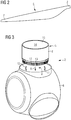
- FIG. 2 depicts a rotor blade 5 of the wind turbine 1.
- the rotor blade 5 includes a tip end 7 and a root end 8.
- FIG. 3 depicts a schematic view of the root end 8 of the rotor blade 5 being connected to a hub 6 of the wind turbine 1 (the rotor 2).
- a plurality of bolt connections 13 attach the rotor blade 5 to the hub 6.
- the rotor blade 5 is attached via bolted connections 13 to a blade-bearing of the hub 6.
- These bolted connections 13 need to be tightened over time, particularly during service of the wind turbine.
- Other types of bolted connections 13 connecting wind turbine components include tower flanges of two wind turbine tower sections.
- connections of the wind turbine 1 that are connected with a ring of bolts and corresponding nuts.
- such connections may be present between the two rotor components or between a rotor component and a rotating part of a bearing arrangement.
- a yawing component such bolted connections 13 may be used to connect two components of the wind turbine 1.
- FIG. 4 depicts a section of an assembled ring for a wind turbine blade 5 connected to the hub 6 (see e.g. fig. 3 ), in accordance with embodiments of the present invention.
- the section of the assembled ring includes a plurality of bolts 13a with a thread at the end, together with nuts 13b that are screwed on the threaded bolts 13a. These are the nuts 13b that will need to be tightened from time to time.
- Embodiments of the present invention include an automated bolt tensioning device 20 that automatically tightens existing bolt connections 13 (i.e. threaded bolt 13a and corresponding nut 13b) of an operational wind turbine 1, such as those shown in FIG. 4 .
- a preferred configuration is a circular arrangement of bolts 13a.
- the distance of the bolts 13a may be substantially equidistant to another throughout the complete ring.
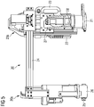
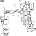
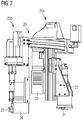
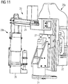
- FIGs. 5-13 depict various views of an automated bolt tensioning device 20, in accordance with embodiments of the present invention.
- the automated bolt tensioning device 20 is preferably a tool that can be temporarily placed onto the bolt connections 13.
- the device 20 is a robot capable of programmable movement along existing bolt connections 13 connecting two or more wind turbine components together.
- the device 20 reduces a number of technicians required to perform bolt tightening tasks from two to one, and collects data to determine if the nuts/bolts are loosening between service intervals.
- the device 20 is a fully-functional automated device capable of repeatedly tightening bolts 13a within various locations of an operational wind turbine 1 (e.g. hub, tower, etc.) to a specified tension range.
- the device 20 may include obstacle detection, alignment, an operational graphical user interface, and nut rotation data acquisition for reduced turbine preventative maintenance cost.
- the device 20 includes a first unit 20a and a second unit 20b.
- the first unit is configured to be releasably secured to existing bolt connections 13, for example, bolt connections 13 between a rotor blade 5 and a blade-bearing - particularly the blade bearing of a pitching mechanism of the wind turbine blades 5 - of the hub 6.
- the first unit 20a is a first leg 20a that includes an attachment means 21 (e.g. an attachment base 21) located at a bottom end of the first leg 20a for threading the first leg 20a onto a first existing bolt connection 13.
- the attachment means 21 threadably attaches the first unit 20a to a stud protrusion of existing bolt connections 13.
- a motor controls the threading of the first unit 20a to existing bolt connections 13.
- the attachment means 21 includes an extension that couples to a stud protrusion adjacent the first existing bolt connection 13 or added support during an anchoring process of anchoring the device 20 down as the second unit 20b tightens a bolt connection 13 and advances to a further bolt connection 13.
- the first unit 20a includes a Z axis slide 27 permitting a vertical movement of the second unit 20b and the first unit 20a. So respective units can move up and down in respect of the bolt connections 13.
- the second unit 20b is moved along the Z axis by actuating the Z slide 27 mounted to the first unit 20a because the slide arm 24 connects the second unit 20b to the first unit 20a.
- the Z slide 27 permits a vertical movement of the second unit 20b from a position above a bolt connection 13 to a position of contact with the bolt connection 13, and then back to a position above the bolt connection 13.
- the Z slide 27 permits a vertical movement of the first unit 20a from a position of contact with the bolt connection 13 to a position above a first bolt connection 13.
- the Z slide 27 permits the first unit 20a and/or the second unit 20b to be lowered onto bolt connections 13 of the wind turbine tower.
- a motor - or one motor for each of the units - controls the actuation of the Z slide 27.
- the first unit 20a comprises an electronic 22 to control the movements of the device 20 and an ergonomic handle 23 to manually carry and apply the device 20 to a bolt connection 13.
- the second unit 20 is configured to tighten the existing bolt connections 13.
- the second unit 20a includes a bolt tensioning assembly for tightening an existing bolt connection 13.
- the tensioning assembly includes a tensioner threader for threading a tensioner 26 (e.g. a TenTec Tensioner) onto a stud protrusion of existing bolt connections 13, encoders, a tensioner 26 for tensioning the existing bolt connections 13, and a torque application device for applying torque to a nut 13b of the existing bolt connections 13 after a bolt 13a has been tensioned by the tensioner 26.
- the tensioning assembly forms, at least partly, the second leg 20b of the device 20.
- a motor controls the tensioning threader for threading the tensioner 26 on the bolt 13a to be tightened, and a separate motor controls the torque application device for turning the nut 13b after the bolt 13a has been tensioned.
- the second unit 20b comprises an adaptor that is dimensioned to fit to the nut 13b which is to be tightened.
- the robot may be able to change autonomously adaptors based on a size of the upcoming one of the to be tightened nuts 13b in case different size nuts are present on the ring of bolt connections 13.
- the robot is able to change adaptors autonomously in case different size nuts are present on the ring of bolt connections 13. This change is especially based on the size of a nut 13b that has to be tightened next.
- the second unit 20b comprises a sensor mount 25 to mount a number of sensors on the second unit 20b.
- the device 20 also includes a slide arm 24 connecting the second unit 20b to the first unit 20a.
- the slide arm 24 facilitates generally horizontal movement of the first unit 20a and the second unit 20b.
- the first unit 20a and the second unit 20b are each movable so that the device 20 can automatically advance to adjacent existing bolt connections 13.
- the slide arm 24 is a slide rail that may also be referred to as a X slide 24 because the movement generally occurs along the X axis, wherein a X axis and a Y axis define a plane in which the bolt connections 13 are arranged.
- a motor controls the actuation of the slide arm 24.
- the slide arm 24 can be customized to the dimension of the bolted joint being tightened; the device 20 can utilize the existing wind turbine hardware as an anchor to "walk" from one bolt to the next, or skip bolts 13a in between for larger tightening intervals.
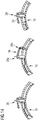
- the left picture shows the starting at a bolt that can be designated "bolt 1" (e.g. a Pitch Ramp).
- Bolt 1 e.g. a Pitch Ramp
- This item is a steel ramp structure bolted to the blade bearing, and features three holes in the ramp to allow for a hydraulic piston to drop into any of the three holes to provide a mechanical locking mechanism to prevent unintentional movement of the blade.
- the picture in the middle shows a state where the tensioner moves to the fifth bolt (seen from bolt 1).
- the right picture shows a state where the tensioning is done. Once done tensioning, the threader follows. This action of the three pictures is repeated.
- the picture further show marked areas of the bolts.
- the robot can measure how strong the bolts had been fastened or if there have been loosened bolts. These areas could be identified and e.g. shown on a screen marked with colors where green can designate e.g. oil absorber pads (often installed in the sides of the blade bearing, designed to absorb any excess water/grease/oil which could be introduced into the hub area), yellow means "questionable” and red mark "no-go” states.
- the first unit 20a is connected to one or two bolt connections 13 to anchor the device 20.
- the connection involves a hollow, internally threaded attachment means 21 (see e.g. one of Figures 5-13 ) that threads onto the external threads of a stud protrusion of an existing bolt connection 13, as shown in FIG. 12 .
- the second unit 20b is placed over a further bolt 13a and nut 13b of a further bolt connection 13 a distance away from the two bolt connections occupied by the first unit 20a. Once in position, the second unit 20b is then lowered onto the further bolt connection 13 to tighten the nut 13b.
- the second unit 20b is lifted away from the bolt connection 13 and then moved generally horizontally by actuation of the slide arm 24 over the next bolt connection 13; the first unit 20a remains in the anchoring position.
- the second unit 20b is lowered onto this next bolt connection 13 to tighten the next nut 13b.
- This progression by the second unit 20b can be done for a few bolt connections 13 - for example up to five, up to four, or up to three bolt connections 13, and preferably at least two, at least three, or at least four connections - depending on a length of the slide arm 24 between the first unit 20a and the second unit 20b.
- the first unit 20a is loosened from its position, lifted (in Z axis direction), moved a few bolts closer to the second unit 20b, and then lowered and connected again onto two bolts. These two bolts now act as solid basement for the next operating steps of the robot.
- the second unit 20b remains in tight contact with a bolt connection 13. The whole process can start over again to service the existing bolt connections 13, that is, the nut and the bolt, of the component.
- the device 20 may crawl around the circle of bolts without further manual interaction.
- the device 20 will have to periodically pause its operation until a technician manually pitches the rotor blade 5 to a new position to access more bolts due to obstacles in a travel path of the device 20.
- One or more sensors detect the obstacles along a travel path of the device 20 as the device automatically advances to adjacent existing bolt connections 13. Once such a sensor detects an obstacle along the travel path of the device 20, the device will pause its operation.
- a signal is provided to an operator person or a control device.
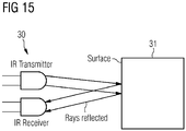
- FIG. 15 depicts a schematic view of an infrared sensor 30 detecting an object 31, in accordance with embodiments of the present invention.
- the one or more or sensors include an infrared sensor 30 and/or a camera (e.g. canny edge detection) positioned on the second unit 20b using a sensor mount 25, for example.
- a camera e.g. canny edge detection
- the device 20 would be able to travel the full circle unimpeded.
- the device 20 is designed/optimized for the blade-to-blade-bearing connection, such that the slide arm 24 is a curved rail designed to match a curvature of the bolted joints of the blade-to-blade bearing connection.
- the slide arm 24 could be exchanged for different sizes/curvatures so the device 20 can tighten other bolted connections (e.g. tower flanges).
- the slide arm 24 is curved (as shown in FIG. 6 ) and has a curvature that corresponds to a curvature of the existing bolt connections 13 on a wind turbine component of the wind turbine 1.
- the automated bolt tensioning device 20 reduces a number of required technicians from two or more to one, where multiple devices 20 could be supervised by the same technician(s). Automating the device's operation improves the ergonomics of the task and reduces risk to technician safety. In situations where many bolts need to be tightened, the device 20 can execute the task faster than a human team. The repeatability of the device 20 ensures quality of the task performed and consistency in the values with which the bolts are tightened, significantly reducing risk of improper workmanship. Further, the automatization of the task via the device 20 removes the technician from executing the work; instead the technician can set up the device 20 and manipulate the data collected, leaving the technician free to perform other tasks while the device 20 executes its work.
- the device 20 also collects data to determine if the nuts/bolts are loosening between service intervals.
- At least one RFID antenna is used by the device 20 for emitting an electromagnetic field to energize a RFID tag associated with each of the existing bolt connections 13.
- the data received from the energized RFID tag is used to analyze whether the existing bolt connection 13 have loosened over time.
- the data collected can use RFID tags and performance indicators from the robot to uniquely track the bolt being tightened and to what pressure/tension/torque value.
- a singe RFID per ring could also be used, but using one RFID tag per bolt ensures a unique identifier per bolt, which is helpful in case of a bolt replacement (i.e. would require new RFID tag) and reduces complexity of programming the device. It also ensures that technicians do not accidentally re-tighten a bolt that was previously tightened (the robot is programmed to avoid duplicate tightenings within a certain time frame).
- the device 20 may submit collected data, after tightening bolt connections 13, to a supervisory controller, so that this information can be stored in a central service database. Data in such a service database can then be used to schedule service intervals.
- Embodiments of the device 20 further includes a control unit 22 configured to control a movement of the first unit 20a and the second unit 20b.
- the control unit 22 and other electronics 22 are contained within a housing attached to the first unit 20a, as shown in FIGs. 11 and 12 .
- the device 20 uses the existing turbine structure (e.g. the bolts themselves) to physically "walk” from bolt to bolt, and does not utilize auxiliary systems (e.g. rails, platforms, etc.) to maneuver itself in the working environment. Furthermore, the device 20 is designed to operate in an assembled wind turbine 1 or any other assembled machine, different to usual robots in manufacturing that are operated in an assembly or manufacturing workshop.
- FIG. 16 depicts the automated bolt tensioning device 20 placed on studs, in accordance with embodiments of the present invention. The device 20 works on the blade studs, which are the studs that hold the wind turbine blade 5 onto the blade bearing, which is then mounted onto the hub 6.
- the device 20 reduces labor costs associated with bolt tightening and improves understanding of bolted joint behavior using data collection and analysis.
- Bolt tightening operations can be scaled up with the device, being performed at once by utilizing more than one device 20. Technicians will be exposed to safer working conditions, removing themselves from the task itself and supervise the device 20 operation and ensure the device 20 properly executes its function and validates data collection. Data collection on nut/bolt can be used to potentially extend service intervals for particular bolted connections 13 (e.g. if a joint remains tight year after year - based on data collection - it may only need to be inspected/re-tightened every X years instead of every one year).
- the device 20 regulates and verifies that the proper values are used to tighten each bolt and achieved during the tightening process.
- the device 20 may even interact with the wind turbine controller. Once the device identifies an obstruction or whether its orientation cannot guarantee safe processing of the work - for example if the device would be upside down - it could demand from the turbine controller to activate a rotation of the main rotor, and/or the yawing motor, and/or the pitching mechanism, so that the bolt connections will be repositioned so that the robot can continue to autonomously tighten further bolt connections 13.
- the task could similarly be performed by a robotic arm centrally mounted relative to the bolted joint being tightened.
- the centrally mounted robotic arm may be larger and heavier than the device described above and may be operated with a support system (e.g. rail) for such a centrally mounted robot.
Landscapes
- Engineering & Computer Science (AREA)
- Mechanical Engineering (AREA)
- Wind Motors (AREA)
Priority Applications (5)
| Application Number | Priority Date | Filing Date | Title |
|---|---|---|---|
| EP19188050.9A EP3769904A1 (fr) | 2019-07-24 | 2019-07-24 | Robot de tension automatique de boulon |
| EP20721456.0A EP3934843A1 (fr) | 2019-04-18 | 2020-04-14 | Robot de tension de boulon automatisé |
| US17/603,192 US12122003B2 (en) | 2019-04-18 | 2020-04-14 | Automated bolt tensioning robot |
| PCT/EP2020/060419 WO2020212323A1 (fr) | 2019-04-18 | 2020-04-14 | Robot de tension de boulon automatisé |
| CN202080044485.8A CN113966261B (zh) | 2019-04-18 | 2020-04-14 | 自动螺栓张紧机器人 |
Applications Claiming Priority (1)
| Application Number | Priority Date | Filing Date | Title |
|---|---|---|---|
| EP19188050.9A EP3769904A1 (fr) | 2019-07-24 | 2019-07-24 | Robot de tension automatique de boulon |
Publications (1)
| Publication Number | Publication Date |
|---|---|
| EP3769904A1 true EP3769904A1 (fr) | 2021-01-27 |
Family
ID=67438690
Family Applications (1)
| Application Number | Title | Priority Date | Filing Date |
|---|---|---|---|
| EP19188050.9A Withdrawn EP3769904A1 (fr) | 2019-04-18 | 2019-07-24 | Robot de tension automatique de boulon |
Country Status (1)
| Country | Link |
|---|---|
| EP (1) | EP3769904A1 (fr) |
Cited By (6)
| Publication number | Priority date | Publication date | Assignee | Title |
|---|---|---|---|---|
| EP3871829A1 (fr) * | 2020-02-27 | 2021-09-01 | Hohmann, Jörg | Procédé de serrage de raccords à vis, dispositif à vis multiples |
| CN114799852A (zh) * | 2022-06-29 | 2022-07-29 | 广东科凯达智能机器人有限公司 | 一种风电塔筒作业机器人及作业方法 |
| CN114833561A (zh) * | 2021-02-01 | 2022-08-02 | 弗兰克·霍曼 | 用于螺纹连接件的紧固装置与安全装置的布置结构 |
| CN116372555A (zh) * | 2023-03-28 | 2023-07-04 | 上海电力大学 | 一种自行走风电塔筒螺栓拉伸紧固机器人及紧固点检方法 |
| CN117484160A (zh) * | 2023-12-05 | 2024-02-02 | 中建八局新型建造工程有限公司 | 钢箱梁用高强度螺栓自动施拧装置及其施工方法 |
| CN119589386A (zh) * | 2025-01-13 | 2025-03-11 | 上海中帧机器人控制技术发展有限公司 | 一种风电机组法兰螺栓步进式自动张拉装置 |
Citations (9)
| Publication number | Priority date | Publication date | Assignee | Title |
|---|---|---|---|---|
| JPH01103240A (ja) * | 1987-10-16 | 1989-04-20 | Mitsubishi Heavy Ind Ltd | フランジボルトの自動歩行式締緩装置 |
| JPH01216730A (ja) * | 1988-02-23 | 1989-08-30 | Mitsubishi Heavy Ind Ltd | フランジボルト自動締緩装置の制御方法 |
| JPH06206128A (ja) * | 1993-01-11 | 1994-07-26 | Toshiba Corp | 大径ナット締付装置 |
| KR20130026039A (ko) * | 2011-09-05 | 2013-03-13 | 삼성중공업 주식회사 | 풍력 발전기의 유지보수 로봇 |
| EP2607685A1 (fr) * | 2011-12-21 | 2013-06-26 | Kenneth Johst | Robot de montage et serrage de boulons pour éoliennes |
| EP2653273A1 (fr) * | 2010-12-16 | 2013-10-23 | Samsung Heavy Ind. Co., Ltd. | Robot d'assemblage et de gestion d'éolienne et système d'éolienne comportant ce robot |
| US20140306574A1 (en) * | 2013-04-16 | 2014-10-16 | Michael Twerdochlib | Bolt tightener device for tightening a through-bolt in a generator core |
| EP3163071A1 (fr) * | 2015-10-29 | 2017-05-03 | ALSTOM Renewables Technologies Wind B.V. | Serrage automatique de boulons |
| EP3195991A1 (fr) * | 2016-01-21 | 2017-07-26 | Admede Ab | Robot avec moyen de positionnement pour déplacer un outil le long d'un joint à brides |
-
2019
- 2019-07-24 EP EP19188050.9A patent/EP3769904A1/fr not_active Withdrawn
Patent Citations (9)
| Publication number | Priority date | Publication date | Assignee | Title |
|---|---|---|---|---|
| JPH01103240A (ja) * | 1987-10-16 | 1989-04-20 | Mitsubishi Heavy Ind Ltd | フランジボルトの自動歩行式締緩装置 |
| JPH01216730A (ja) * | 1988-02-23 | 1989-08-30 | Mitsubishi Heavy Ind Ltd | フランジボルト自動締緩装置の制御方法 |
| JPH06206128A (ja) * | 1993-01-11 | 1994-07-26 | Toshiba Corp | 大径ナット締付装置 |
| EP2653273A1 (fr) * | 2010-12-16 | 2013-10-23 | Samsung Heavy Ind. Co., Ltd. | Robot d'assemblage et de gestion d'éolienne et système d'éolienne comportant ce robot |
| KR20130026039A (ko) * | 2011-09-05 | 2013-03-13 | 삼성중공업 주식회사 | 풍력 발전기의 유지보수 로봇 |
| EP2607685A1 (fr) * | 2011-12-21 | 2013-06-26 | Kenneth Johst | Robot de montage et serrage de boulons pour éoliennes |
| US20140306574A1 (en) * | 2013-04-16 | 2014-10-16 | Michael Twerdochlib | Bolt tightener device for tightening a through-bolt in a generator core |
| EP3163071A1 (fr) * | 2015-10-29 | 2017-05-03 | ALSTOM Renewables Technologies Wind B.V. | Serrage automatique de boulons |
| EP3195991A1 (fr) * | 2016-01-21 | 2017-07-26 | Admede Ab | Robot avec moyen de positionnement pour déplacer un outil le long d'un joint à brides |
Cited By (11)
| Publication number | Priority date | Publication date | Assignee | Title |
|---|---|---|---|---|
| EP3871829A1 (fr) * | 2020-02-27 | 2021-09-01 | Hohmann, Jörg | Procédé de serrage de raccords à vis, dispositif à vis multiples |
| US11278995B2 (en) | 2020-02-27 | 2022-03-22 | Jörg Hohmann | Method for tightening screwed connections, multi-screwing device |
| CN114833561A (zh) * | 2021-02-01 | 2022-08-02 | 弗兰克·霍曼 | 用于螺纹连接件的紧固装置与安全装置的布置结构 |
| US20220241912A1 (en) * | 2021-02-01 | 2022-08-04 | Frank Hohmann | Arrangement of a Tightening Device for a Screw Connection and a Safety Device |
| JP2022117971A (ja) * | 2021-02-01 | 2022-08-12 | ホーマン フランク | ねじ締結体用の締付け装置と、安全装置とから成るアセンブリ |
| US12296419B2 (en) * | 2021-02-01 | 2025-05-13 | Frank Hohmann | Arrangement of a tightening device for a screw connection and a safety device |
| CN114799852A (zh) * | 2022-06-29 | 2022-07-29 | 广东科凯达智能机器人有限公司 | 一种风电塔筒作业机器人及作业方法 |
| CN114799852B (zh) * | 2022-06-29 | 2022-09-30 | 广东科凯达智能机器人有限公司 | 一种风电塔筒作业机器人及作业方法 |
| CN116372555A (zh) * | 2023-03-28 | 2023-07-04 | 上海电力大学 | 一种自行走风电塔筒螺栓拉伸紧固机器人及紧固点检方法 |
| CN117484160A (zh) * | 2023-12-05 | 2024-02-02 | 中建八局新型建造工程有限公司 | 钢箱梁用高强度螺栓自动施拧装置及其施工方法 |
| CN119589386A (zh) * | 2025-01-13 | 2025-03-11 | 上海中帧机器人控制技术发展有限公司 | 一种风电机组法兰螺栓步进式自动张拉装置 |
Similar Documents
| Publication | Publication Date | Title |
|---|---|---|
| US12122003B2 (en) | Automated bolt tensioning robot | |
| EP3769904A1 (fr) | Robot de tension automatique de boulon | |
| EP3163071B1 (fr) | Serrage automatique de boulons | |
| CN111656009B (zh) | 用于螺栓自动张紧的方法及螺栓张紧系统 | |
| EP2607685B1 (fr) | Robot de montage et serrage de boulons pour éoliennes | |
| JP6713762B2 (ja) | 建設作業用ロボットおよび建設作業用ロボットの制御方法 | |
| KR101194576B1 (ko) | 풍력 터빈 조립 및 관리 로봇 및 이를 포함하는 풍력 터빈 시스템 | |
| KR20130026039A (ko) | 풍력 발전기의 유지보수 로봇 | |
| Iturralde et al. | A cable driven parallel robot with a modular end effector for the installation of curtain wall modules | |
| US20220339636A1 (en) | Automatic device or tool for removing and installing means for fastening liner in a mill method for installing the means for fastening a liner and method for removing the means for fastening a liner | |
| CN120395406A (zh) | 一种水轮机球阀大型螺母的自动装配系统及方法 | |
| CN115057245B (zh) | 一种基于总线控制器与伺服系统的拆码垛系统 | |
| EP3323129B1 (fr) | Ensemble plate-forme de travail automatisée | |
| AU2019464377A1 (en) | System and method for changing a mill liner, configured to allow the fully automated and robotic manipulation of the method | |
| JP6662664B2 (ja) | 回転締結部材の操作方法 | |
| KR870000801B1 (ko) | 증기발생기의 자동원격조종 보수장비 | |
| CN119369084B (zh) | 一种钢结构屋面杆件自动化安装设备及方法 | |
| Heuer et al. | Deconstruction system for the reuse of concrete building parts in circular automated construction | |
| US11891984B2 (en) | Wind turbine apparatus | |
| CN121272783A (zh) | 一种单轨行走式铁路扣件检修机器人及其使用方法 | |
| CN119549314A (zh) | 变电站的漆料喷涂系统、方法、装置及电子设备 | |
| KR100963526B1 (ko) | 원자로용 호이스트 포지션 판단장치 | |
| CN117816595A (zh) | 一种用于竖直绝缘子串的结构自适应移动清理一体机器人 | |
| CN120418035A (zh) | 在线的旋拧方法及对旋拧操作进行控制的方法 | |
| DK202330131A1 (en) | Service robot for wind turbines and navigation method thereof |
Legal Events
| Date | Code | Title | Description |
|---|---|---|---|
| PUAI | Public reference made under article 153(3) epc to a published international application that has entered the european phase |
Free format text: ORIGINAL CODE: 0009012 |
|
| STAA | Information on the status of an ep patent application or granted ep patent |
Free format text: STATUS: THE APPLICATION HAS BEEN PUBLISHED |
|
| AK | Designated contracting states |
Kind code of ref document: A1 Designated state(s): AL AT BE BG CH CY CZ DE DK EE ES FI FR GB GR HR HU IE IS IT LI LT LU LV MC MK MT NL NO PL PT RO RS SE SI SK SM TR |
|
| STAA | Information on the status of an ep patent application or granted ep patent |
Free format text: STATUS: THE APPLICATION IS DEEMED TO BE WITHDRAWN |
|
| 18D | Application deemed to be withdrawn |
Effective date: 20210728 |