EP3770023B1 - Elektrische laufschienensysteme für flugzeuge und verfahren - Google Patents
Elektrische laufschienensysteme für flugzeuge und verfahren Download PDFInfo
- Publication number
- EP3770023B1 EP3770023B1 EP20184230.9A EP20184230A EP3770023B1 EP 3770023 B1 EP3770023 B1 EP 3770023B1 EP 20184230 A EP20184230 A EP 20184230A EP 3770023 B1 EP3770023 B1 EP 3770023B1
- Authority
- EP
- European Patent Office
- Prior art keywords
- wiring
- wire group
- wires
- track
- connector
- Prior art date
- Legal status (The legal status is an assumption and is not a legal conclusion. Google has not performed a legal analysis and makes no representation as to the accuracy of the status listed.)
- Active
Links
Images




Classifications
-
- B—PERFORMING OPERATIONS; TRANSPORTING
- B60—VEHICLES IN GENERAL
- B60R—VEHICLES, VEHICLE FITTINGS, OR VEHICLE PARTS, NOT OTHERWISE PROVIDED FOR
- B60R16/00—Electric or fluid circuits specially adapted for vehicles and not otherwise provided for; Arrangement of elements of electric or fluid circuits specially adapted for vehicles and not otherwise provided for
- B60R16/02—Electric or fluid circuits specially adapted for vehicles and not otherwise provided for; Arrangement of elements of electric or fluid circuits specially adapted for vehicles and not otherwise provided for electric constitutive elements
- B60R16/0207—Wire harnesses
- B60R16/0215—Protecting, fastening and routing means therefor
-
- H—ELECTRICITY
- H02—GENERATION; CONVERSION OR DISTRIBUTION OF ELECTRIC POWER
- H02G—INSTALLATION OF ELECTRIC CABLES OR LINES, OR OF COMBINED OPTICAL AND ELECTRIC CABLES OR LINES
- H02G3/00—Installations of electric cables or lines or protective tubing therefor in or on buildings, equivalent structures or vehicles
- H02G3/02—Details
- H02G3/04—Protective tubing or conduits, e.g. cable ladders or cable troughs
- H02G3/0456—Ladders or other supports
-
- H—ELECTRICITY
- H02—GENERATION; CONVERSION OR DISTRIBUTION OF ELECTRIC POWER
- H02G—INSTALLATION OF ELECTRIC CABLES OR LINES, OR OF COMBINED OPTICAL AND ELECTRIC CABLES OR LINES
- H02G1/00—Methods or apparatus specially adapted for installing, maintaining, repairing or dismantling electric cables or lines
- H02G1/06—Methods or apparatus specially adapted for installing, maintaining, repairing or dismantling electric cables or lines for laying cables, e.g. laying apparatus on vehicle
-
- H—ELECTRICITY
- H02—GENERATION; CONVERSION OR DISTRIBUTION OF ELECTRIC POWER
- H02G—INSTALLATION OF ELECTRIC CABLES OR LINES, OR OF COMBINED OPTICAL AND ELECTRIC CABLES OR LINES
- H02G3/00—Installations of electric cables or lines or protective tubing therefor in or on buildings, equivalent structures or vehicles
- H02G3/02—Details
- H02G3/04—Protective tubing or conduits, e.g. cable ladders or cable troughs
- H02G3/0437—Channels
-
- B—PERFORMING OPERATIONS; TRANSPORTING
- B64—AIRCRAFT; AVIATION; COSMONAUTICS
- B64D—EQUIPMENT FOR FITTING IN OR TO AIRCRAFT; FLIGHT SUITS; PARACHUTES; ARRANGEMENT OR MOUNTING OF POWER PLANTS OR PROPULSION TRANSMISSIONS IN AIRCRAFT
- B64D31/00—Power plant control systems; Arrangement of power plant control systems in aircraft
- B64D31/14—Transmitting means between initiating means and power plants
Definitions
- the disclosure relates generally to aircraft electrical systems and, more particularly, to electrical racetracks used in aircraft electrical systems.
- Aircraft wiring systems generally include a collection of different types of wires.
- the wires are placed in prefabricated wire bundles that are terminated into individual connectors.
- the bundles are then installed on the racetracks.
- Such fabrication and installation can include many manual processes that can introduce human error, lead to quality issues, increase fabrication costs, and decrease fabrication throughput.
- the connectors used in current racetrack fabrication can result in poor ergonomic working conditions within confined spaces when the racetrack is installed into the aircraft and the interfacing connectors are mated.
- Document EP 2 482 401 A2 states in its abstract a cable raceway assembly having channel sections with protrusions and clamp insertable with recesses engageable with the protrusions providing a snap-fit ratchet-type engagement.
- Document DE 10 2016 115706 A1 states in its abstract a cable duct for a vehicle, comprising a cable duct housing, which forms a receiving space for a plurality of substantially flexible conductors. At least one rail receptacle for guiding and / or holding at least one essentially dimensionally stable flat conductor rail is formed in or on the cable duct housing.
- Document EP 1 258 961 A2 states in its abstract a means for improving the electronic and electromagnetic isolation characteristics of compartments within cable trunking systems.
- cable trunking is provided in sections having covers which enclose cables disposed in the trunking, and more specifically compartments thereof.
- the compartments are defined by one or more walls extending upwardly from a base section to which one or more covers is attached one or more covers, said base section having a base to complete the compartment so that cables can be safely contained therein.
- data cables carrying low voltage signals are prone to electromagnetic interference from power cables, and these two types of cable are commonly disposed in separate compartments within the trunking.
- a metallic plate is disposed adjacent the walls to provide a shielding effect for said data cables, at least a portion of said metallic plate being deformed out of the plane of said plate to provide a contact with which an electrical connection can be made to permit that plate to be electrically connected to an adjacent metallic plate having a similar contact and similarly disposed adjacent one of the walls.
- the walls are provided at their free end with a flange having a depending skirt to define an upper channel, and a rib is provided on the base adjacent the wall where it joins the base to provide a lower channel so that the metallic plates in the form of strips can be slid along and retained within the channels to facilitate compartment isolation quickly and simply.
- the present invention relates to an aircraft according to claim 1 and to a method according to claim 8.
- the wiring racetrack includes a first wire group, a second wire group, and a wiring pallet.
- the first wire group includes wires of exclusively a first category.
- the second wire group includes wires of exclusively a second category distinct from the first category.
- the wiring pallet includes a first track and a second track.
- the first wire group is contained exclusively within the first track.
- the second wire group is contained exclusively within the second track.
- a first connector is electrically coupled to each of the wires of the first wire group and a second connector is electrically coupled to each of the wires of the second wire group.
- the systems and techniques described herein allow for modular electrical systems to be incorporated into an aircraft. Additionally, the systems and techniques allow for automated manufacturing of the electrical racetracks. As such, recurring electrical fabrication and installation costs can be reduced. Additionally, electrical racetracks can be improved in quality, maintainability, organization, space efficiency, and reliability. Furthermore, the modular nature of the systems can allow for reduced engineering costs and increase the ease of design.
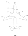
- Fig. 1 illustrates an aircraft in accordance with an example of the disclosure.
- the aircraft 100 of Fig. 1 can include fuselage 170, wings 172, horizontal stabilizers 174, aircraft engines 176, and vertical stabilizer 178. Additionally, aircraft 100 can include cockpit electronics 110, controller 108, and wiring 112.
- Aircraft 100 described in Fig. 1 is exemplary and it is appreciated that in other examples, aircraft 100 can include more or less components or include alternate configurations. Additionally, concepts described herein can be extended to other aircraft such as helicopters, drones, missiles, etc.
- Cockpit electronics 110 can be electronics for control or operation of various systems of the aircraft 100.
- Cockpit electronics 110 can be disposed within the cockpit of the aircraft 100.
- Cockpit electronics 110 can be electrically coupled (e.g., coupled so that electrical current can be communicated) to one or more other systems of the aircraft 100 through wiring 112.
- Wiring 112 can be a wiring system that includes electrical wires disposed within one or more wiring racetracks. Wiring 112 can include subsystems that are electrically coupled with various connectors.
- Wiring 112 can, thus, couple the cockpit electronics 110 to systems such as controller 108, aircraft engines 176, and various cabin systems, flight control systems, communications systems, and other systems. Additionally, wiring 112 can also electrically couple other electrical systems of the aircraft 100, additional or alternative to the cockpit electronics 110.
- Controller 108 and cockpit electronics 110 can include, for example, a microprocessor, a microcontroller, a signal processing device, a memory storage device, and/or any additional devices to perform any of the various operations described herein.
- controller 108 and/or its associated operations can be implemented as a single device or multiple connected devices (e.g., communicatively linked through wired or wireless connections such as wiring 112).
- cockpit electronics 110 and controller 108 can include one or more memory components or devices to store data and information.
- the memory can include volatile and nonvolatile memory. Examples of such memory include RAM (Random Access Memory), ROM (Read-Only Memory), EEPROM (Electrically-Erasable Read-Only Memory), flash memory, or other types of memory.
- cockpit electronics 110 and controller 108 can be adapted to execute instructions stored within the memory to perform various methods and processes described herein, including implementation and execution of control algorithms responsive to sensor and/or operator (e.g., flight crew) inputs.
- Aerodynamic surfaces can be surfaces that generate lift, downforce, and/or otherwise affect the stability or flight of the aircraft 100.
- Fig. 2 illustrates a prior art wiring racetrack .
- Fig. 2 is a cross-sectional view of wiring racetrack 200.
- Wiring racetrack 200 is an example of a conventional wiring racetrack installed on an aircraft.
- Wiring racetrack 200 includes a raceway 202 with wiring bundles 204A-I coupled to wiring raceway 202.
- Wiring bundles 204A-I can be pre-fabricated wiring bundles that each include one or more wires.
- wiring bundles 204A-I can contain a plurality of different types of wires of different categories. As such, one or more wiring bundles 204A-I can include mixed categories of wires. Furthermore, the wires of the same or a similar category can be dispersed across many different locations on wiring raceway 202. Thus, design, fabrication, and maintenance of the wiring racetrack 200 can require a significant amount of time and manpower.
- each wire of wiring bundles 204A-I is assigned a unique category based on separation and redundancy requirements (e.g., as dictated by a certification authority). For example, a wire of one category one can be assigned to control a specific aerodynamic surface on the wing. Based on this categorization, that wire should be separated from other wires that control, for example, the lights, sensors, different control surfaces, or other parts of the aircraft. Wires associated with different systems of the aircraft are thus divided into separate routing paths (groups or categories) based on certification requirements for separation and/or redundancy purposes.
- Fig. 3 illustrates a wiring pallet in accordance with an example of the disclosure.
- Fig. 3 illustrates a wiring pallet 304 with tracks 306A-G.
- tracks 306A-G can be configured to each contain a limited number of categories of wires (e.g., one or two different categories of wires).
- One or more of tracks 306A-G can be different sizes depending on the number and volume of wiring for each wiring category.
- Fig. 3 illustrates wiring pallet 304 with open channels
- one, more than one, or all sections of other examples of wiring pallet 304 can include closed channels.
- Wiring pallet 304 can be divided into one or more sections. The sections can be combined to constitute wiring pallet 304.
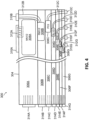
- Fig. 4 illustrates a wiring racetrack in accordance with an example of the disclosure.
- Fig. 4 illustrates wiring racetrack 300 with wiring pallet 304 and wiring groups 308A-G.
- Each of wiring groups 308A-G can be accordingly disposed within tracks 306A-G of wiring pallet 304.
- wiring group 308A can be disposed without track 306A while wiring group 308B can be disposed within track 306B.
- Wiring groups 308A-G can be groups with certain specific categories of wires.
- wiring group 308A can be a group of NN1/2 wires.
- Wiring group 308B can be a group of RM1/2 wires.
- Wiring group 308C can be a group of FC2 wires.
- Wiring group 308D can be a group of SL1/2 wires.
- Wiring group 308E can be a group of PR1 wires.
- Wiring group 308F can be a group of SR2 wires.
- Wiring group 308G can be a group of LM2 wires.
- Such wiring categories can be in accordance with FAA specified categories (e.g., separation codes, redundancy, electromagnetic effects, etc.) or other categorization types.
- the wiring groups 308A-G can have more than one category of wires by, for example, additionally including neutral wires (e.g., ground wires, intrinsically safe wiring, etc.) within the group that do not belong to any specific category. Nonetheless, it is appreciated that the wires of a specific category can be exclusively organized into a wiring group. Such a configuration can simplify installation of wires into any associated connectors (e.g., as only one type of wiring is in a group, the connector insert cavity utilization can be optimized).
- neutral wires e.g., ground wires, intrinsically safe wiring, etc.
- wiring group 308A can include 300-500 wires and be a bundle approximately 3.81 to 7.62 cm (1.5 to 3 inches) in diameter.
- Wiring group 308B can include 25-50 wires and be a bundle approximately 2.54 to 5.08 cm (1 to 2 inches) in diameter.
- Wiring group 308C can include 30-60 wires and be a bundle approximately 1.905 to 3.175 cm (0.75 to 1.25 inches) in diameter.
- Wiring group 308D can include 30-60 wires and be a bundle approximately 1.27 to 2.54 cm (0.5 to 1 inch) in diameter.
- Wiring group 308E can include 2-4 wires and be a bundle approximately 0.635 to 1.905 cm (0.25 to 0.75 inches) in diameter.
- Wiring group 308F can include 5-10 wires and be a bundle approximately 0.635 to 1.27 cm (0.25 to 0.5 inches) in diameter.
- Wiring group 308G can include 2-6 wires and be a bundle approximately 0.254 to 0.635 cm (0.1 to 0.25 inches) in diameter.
- the various wires of the wiring groups can be electrically coupled (e.g., can pass electrical current and/or signals to and receive such current and/or signals from) to one or more connectors.
- wiring groups 308A-G can be coupled to connectors 310A-G, respectively, on a first end of the wires and coupled to connectors 314A-G, respectively, on a second end of the wires.
- Certain examples can electrically couple all the wires of a single wiring group to a single connector, but other examples can electrically couple the wires of a single wiring group to a plurality of connectors to, for example, interface with a plurality of systems.
- Connectors 310A-G can be connectors disposed along one or more lateral sides (e.g., as compared to the directions that the wires run) of wiring pallet 304.
- Connectors 310A-G can be configured to be connected to one or more wiring systems of an aircraft. Disposing connectors 310A-G along the lateral sides of wiring pallet 304 can allow for simplified electrical connections to electrical systems of the aircraft disposed to the lateral sides of the wiring pallet 304.
- Wiring groups 308A-G can be connected to respective connectors 310A-G via wiring 312A-G, respectively.
- connectors 310A-G can be integrated along the sides of wiring pallet 304 to allow for a solid connection. Other examples can allow for connectors 310A-G to be relatively loose (e.g., can be moved relative to wiring pallet 304).
- Connectors 314A-G can be connectors disposed within or at the end of tracks 306A-G, respectively. Connectors 314A-G can, thus, electrically couple with other connectors in a longitudinal direction. As such, connectors 314A-G can, for example, allow for electrical coupling to another wiring racetrack or other electrical systems. Longitudinal connectors can also allow for easy extension of the lengths of wiring racetrack 300, allowing for a modular system where longer wiring racetracks can be created (e.g., for longer aircraft) through a combination of multiple racetracks. Through a combination of longitudinal and lateral connectors, wiring racetrack 300 can be connected to various other electrical systems of the aircraft and/or other wiring racetracks to form a modular electrical system.
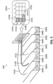
- Fig. 5 illustrates a racetrack wiring system in accordance with an example of the disclosure.
- Fig. 5 illustrates wiring racetrack 300 electrically coupled to connector panel 500 (for example panel 500A in Fig. 5 )A.
- Connector panel 500 can include one or more receiver connectors (i.e., mating connectors), such as receiver connectors 510A-C, configured to mate to connectors of the wiring groups.
- Each receiver connector can include features (e.g., geometric features, dimensions, lead-ins, and other features) that allow for the receiver connector to only connect with a specific connector of the wiring group.
- the connectors (e.g., connectors 310A-C) of the wiring groups e.g., of wiring groups 308A-C) can be connected to receiver connectors (e.g., receiver connectors 510A-C) of connector panel 500.
- Each of the receiver connectors 510A-C can, in certain examples, be configured to receive only wires of a specific category of only wires of such a category as well as any neutral or intrinsically safe wires.
- fabrication of the connector panel 500 e.g., connection of wires to the connector
- connector panel 500 is disposed lateral to wiring racetrack 300.
- Other examples can dispose connector panels longitudinally to the wiring racetrack or in other configurations.
- Connector panel 500 can allow for all wires of a wiring group of the wiring racetrack 300 to be easily coupled to a corresponding receiver connector, decreasing installation time.
- positioning connector panel 500 lateral to wiring racetrack 300 can allow for more direct electrical connections to systems disposed to the side of wiring racetrack 300. Certain such systems are shown in Fig. 6 .
- Fig. 6 illustrates an aircraft with a racetrack wiring system in accordance with an example of the disclosure.
- Fig. 6 illustrates aircraft 100 with wiring racetracks 300A and 300B disposed within left and right portions of the fuselage 170. In certain examples, all wiring within a section of the fuselage 170 can be contained within the respective wiring racetracks 300A and 300B.
- Aircraft 100 also includes secondary routing pathway 600 with integration panel 602 and connector 604. Aircraft 100 additionally includes tertiary routing pathways 606.
- Wiring racetrack 300A can be electrically coupled to secondary routing pathway 600 via connector panels 500C and 500D.
- Connectors panels 500C and 500D can be electrically coupled to integration panel 602 and connector 604.
- electrical current and/or signals from wires of wiring racetrack 300A can be communicated to secondary routing pathway 600.
- Wiring racetrack 300A can also be electrically coupled to tertiary routing pathways 606 through, for example, connector panel 500A.
- Wiring racetrack 300B can be electrically coupled to connector panel 500B and electrically coupled to secondary routing pathway 600 through other connector panels.
- wiring racetracks 300A and 300B are substantially straight. Electrical connections to systems to the side of wiring racetracks 300A and 300B are connected through corresponding connector panels.
- wiring racetracks 300A and 300B can include connectors disposed on lateral sides of wiring racetracks 300A and 300B to electrically couple to such connectors. Fabricating wiring racetracks 300A and 300B to be substantially straight allows for simplified manufacturing as wires would only be required to be run substantially linearly. Bends and/or angular connections in such electrical connections can then be interfaced through corresponding connector panels and/or other connectors.
- Fig. 7 is a flowchart detailing a method of fabricating a racetrack wiring system in accordance with an example of the disclosure. In certain examples, portions or all of the technique detailed in Fig. 7 can be performed by one or more robots or through automated manufacturing.
- a plurality of wires can be sorted into at least a first wire group and a second wire group.
- the first wire group can include wires of exclusively a first category or include wires of the first category and neutral wires.
- the second wire group can include wires of exclusively a second category distinct from the first category or include wires of the second category and neutral wires. Certain other wires can be sorted into additional wire groups of additional categories.
- a wiring pallet can be fabricated.
- the wiring pallet can include a plurality of tracks.
- the wiring pallet can be, for example, a pallet with a plurality of distinct open or closed channels.
- the first wire group can be disposed within a first track of the wiring pallet.
- the second wire group can be disposed within a second track of the wiring pallet.
- Other wiring groups can also be disposed within their own separate tracks of the wiring pallet.
- block 704 can be performed by holding the wiring pallet within a gantry. Additionally, the wiring groups can be tagged according to the separation code of the wiring group. A robot can scan the tags to determine the respective group of the wiring groups. The robot can then dispose the wiring groups within the appropriate tracks of the wiring pallet by gripping each of the wiring groups with an end effector and disposing the wiring groups within the respective tracks. An example of such a robot is described in Fig. 8 .
- the wiring groups can be electrically coupled to corresponding connectors.
- the first wiring group can be electrically coupled to a first connector and the second wiring group can be coupled to a second connector.
- Additional operations to finish the full wiring racetrack can be performed in block 708. Such additional operations can include, for example, coupling connectors to portions of the wiring racetrack, further cable management, and other processes.
- the full wiring racetrack is assembled to an aircraft.
- the wiring racetrack can, thus, be disposed within a section of the aircraft.
- Certain aircraft can require a plurality of wiring racetracks. Such aircraft can be fitted accordingly.
- aircraft electrical systems can be coupled to the wiring racetrack.
- one or more wiring groups can be electrically coupled to one or more aircraft systems.
- Such electrical coupling can include, for example, hard wiring, connectors, and/or other techniques.
- the wiring racetrack can thus be integrated with other electrical systems of the aircraft and, thus, provide electrical power and signal transmission to and from the systems.
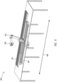
- Fig. 8 illustrates a robotic system in accordance with an example of the disclosure.
- Fig. 8 illustrates a robotic system 800 that includes a robot arm 802, a robotic transfer unit (RTU) 804, an end effector 808 coupled to the robot arm 802, and wiring pallet 304.
- RTU robotic transfer unit
- RTU 804 can move robot arm 802 along direction 806 (e.g., forwards and backwards along direction 806).
- RTU 804 can include associated wire routing and components for moving robot arm 804.
- RTU 804 can be configured to move robot arm 804 in one or more directions to wiring pallet 304.
- robot arm 802 can include one or more scanners configured to scan wiring groups and dispose the wiring groups within appropriate channels of wiring pallet 304.
- the wiring groups can be tagged with the separation code of the wiring group.
- a scanner of robot arm 802 can then scan the tag to determine the respective group for the wiring group.
- Robot arm 802 can then handle (e.g., pick up or otherwise) the wiring group with end effector 808 to dispose the wiring group within the appropriate channel of wiring pallet 304.
- digital data can be used to control the design and manufacturing of wiring racetracks.
- the wires of separate wiring groups are each sorted and/or tagged by digital data that assigns the appropriate connector termination location and category to each individual wire.
- the scanner of robot arm 802 can scan the tagged data.
- End effector 808 can then, using this data, couple the individual wires with the appropriate connector.
- end effector 808 can couple a first wire with a first connector on a first end for a first group, dispose of the first group within an assigned track of wiring pallet 304, and couple the first wire with a second connector on a second end for the first group.
- end effector 808 can additionally couple individual wires (e.g., a second wire) of a second group with a first connector (e.g., the first connector coupled to the first group, for shared connectors, or a different first connector), dispose of the wires of the second group in the assigned track and couple the individual wires of the second group with another connector on a second end. Accordingly, manufacture of the wiring groups and wiring racetracks can be automated.
- individual wires e.g., a second wire
- a first connector e.g., the first connector coupled to the first group, for shared connectors, or a different first connector
Landscapes
- Engineering & Computer Science (AREA)
- Architecture (AREA)
- Civil Engineering (AREA)
- Structural Engineering (AREA)
- Mechanical Engineering (AREA)
- Installation Of Indoor Wiring (AREA)
Claims (15)
- Luftfahrzeug (100) mit:
einem Rumpf (170), der aufweist:einen Verkabelungsspurschacht (300) mit:einer ersten Kabelgruppe (308A), die ein oder mehrere Kabel aus ausschließlich einer ersten Kategorie aufweist;einer zweiten Kabelgruppe (308B), die ein oder mehrere Kabel aus ausschließlich einer zweiten Kategorie aufweist, die sich von der ersten Kategorie unterscheidet;einer Verkabelungspalette (304), die eine erste Spur (306A) und eine zweite Spur (306B) beinhaltet, wobei das eine oder die mehreren Kabel der ersten Kategorie ausschließlich innerhalb der ersten Spur enthalten sind, und wobei das eine oder die mehreren Kabel der zweiten Kategorie ausschließlich innerhalb der zweiten Spur enthalten sind;einem ersten Verbinder (310A; 314A), der elektrisch mit jedem der Kabel der ersten Kabelgruppe (308A) gekoppelt ist, und zwar innerhalb oder an dem Ende der ersten Spur (306A); undeinem zweiten Verbinder (310B; 314B), der elektrisch mit jedem der Kabel der zweiten Kabelgruppe (308B) gekoppelt ist, und zwar innerhalb oder an dem Ende der zweiten Spur (306B); undeine sekundäre Verkabelung (600), die einen oder mehrere Verbinder aufweist, die elektrisch mit dem ersten Verbinder, dem zweiten Verbinder oder sowohl mit dem ersten Verbinder als auch dem zweiten Verbinder gekoppelt ist bzw. sind;wobei die erste Kabelgruppe (308A) elektrisch mit einem ersten Luftfahrzeugsystem gekoppelt ist und wobei die zweite Kabelgruppe (308B) elektrisch mit einem zweiten Luftfahrzeugsystem gekoppelt ist. - Luftfahrzeug nach Anspruch 1, wobei die erste Spur und die zweite Spur Kanäle innerhalb der Verkabelungspalette (304) sind.
- Luftfahrzeug nach Anspruch 1 oder 2, wobei der Rumpf (170) einen Rumpfabschnitt mit einem linken Abschnitt und einem rechten Abschnitt beinhaltet, und wobei der Verkabelungsspurschacht innerhalb des linken Abschnittes oder des rechten Abschnittes angeordnet ist.
- Luftfahrzeug nach Anspruch 3, wobei die gesamte Verkabelung des linken Abschnittes oder des rechten Abschnittes des Rumpfes innerhalb der Verkabelungspalette (304) enthalten sind.
- Luftfahrzeug nach einem beliebigen der Ansprüche 1 bis 4, wobei die erste Kategorie und die zweite Kategorie Kabelkategorien sind, die von einer Aufsichtsbehörde definiert sind.
- Luftfahrzeug nach einem beliebigen der Ansprüche 1 bis 5, wobei der erste Verbinder (310A; 314A) und der zweite Verbinder (310B; 314B) mit einem dazu passenden Verbinder gekoppelt sind, wobei die Verkabelungspalette (304) im Wesentlichen linear ausgebildet ist, und wobei der erste Verbinder und der zweite Verbinder dazu konfiguriert sind, eine Kopplung zu dem dazu passenden Verbinder herzustellen, der unter einem Winkel in Bezug auf die Verkabelungspalette angeordnet ist.
- Luftfahrzeug nach einem beliebigen der Ansprüche 1 bis 6, wobei der Verkabelungsspurschacht ferner eine neutrale Kabelgruppe mit einem oder mehreren Kabeln einer dritten Kategorie beinhaltet, wobei die neutrale Kabelgruppe innerhalb sowohl der ersten Kabelgruppe (308A) als auch der zweiten Kabelgruppe (308B) verteilt ist.
- Verfahren mit:
Herstellen eines Verkabelungsspurschachtes durch:Sortieren (702) einer Vielzahl von Kabeln in wenigstens eine erste Kabelgruppe und eine zweite Kabelgruppe, wobei die erste Kabelgruppe ein oder mehrere Kabel aus ausschließlich einer ersten Kategorie aufweist und wobei die zweite Kabelgruppe ein oder mehrere Kabel aus ausschließlich einer zweiten Kategorie aufweist, die sich von der ersten Kategorie unterscheidet;Anordnen (704) der ersten Kabelgruppe ausschließlich innerhalb einer ersten Spur einer Verkabelungspalette;Anordnen (704) der zweiten Kabelgruppe ausschließlich innerhalb einer zweiten Spur der Verkabelungspalette;elektrisches Koppeln (706) eines ersten Verbinders mit jedem der Kabel der ersten Kabelgruppe, und zwar innerhalb oder an dem Ende der ersten Spur;elektrisches Koppeln (706) eines zweiten Verbinders mit jedem der Kabel der zweiten Kabelgruppe, und zwar innerhalb oder an dem Ende der zweiten Spur;elektrisches Koppeln der ersten Kabelgruppe mit einem ersten Luftfahrzeugsystem; undelektrisches Koppeln der zweiten Kabelgruppe mit einem zweiten Luftfahrzeugsystem. - Verfahren nach Anspruch 8, ferner mit:
Anordnen (710) des Verkabelungsspurschachtes innerhalb eines Rumpfes eines Luftfahrzeuges. - Verfahren nach Anspruch 9, ferner mit dem Schritt des Koppelns (712) des ersten Verbinders und des zweiten Verbinders mit einem dazu passenden Verbinder, der an dem Luftfahrzeug angeordnet ist, wobei der dazu passende Verbinder unter einem Winkel zu der Verkabelungspalette angeordnet ist.
- Verfahren nach einem beliebigen der Ansprüche 8 bis 10, wobei das Herstellen des Verkabelungsspurschachtes automatisch durch einen oder mehrere Roboter durchgeführt wird, der bzw. die ein Gerüst aufweist bzw. aufweisen, das dazu konfiguriert ist, die Verkabelungspalette und eine Endbetätigungseinrichtung zu halten, die dazu konfiguriert ist, die erste Kabelgruppe innerhalb der ersten Spur anzuordnen oder die zweite Kabelgruppe innerhalb der zweiten Spur anzuordnen.
- Verfahren nach einem beliebigen der Ansprüche 8 bis 11, wobei die erste Spur und die zweite Spur Kanäle innerhalb der Verkabelungspalette sind.
- Verfahren nach einem beliebigen der Ansprüche 8 bis 12, wobei das Sortieren (702) der Vielzahl von Kabeln ein Scannen einer Vielzahl von Kabeln beinhaltet, um jedes der Vielzahl von Kabeln als zu der ersten Kabelgruppe oder zu der zweiten Kabelgruppe zugehörig zu identifizieren, und wobei das Scannen der Vielzahl von Kabeln ein Scannen eines Unterscheidungscodes für jedes der Vielzahl von Kabeln beinhaltet.
- Verfahren nach einem beliebigen der Ansprüche 8 bis 13, wobei das Herstellen des Verkabelungsspurschachtes automatisch durch einen oder mehrere Roboter durchgeführt wird, der bzw. die an einer Robotertransfereinheit (RTU) montiert ist bzw. sind, die nahe der Verkabelungspalette und einer Endbetätigungseinrichtung angeordnet ist, die dazu konfiguriert ist, die erste Kabelgruppe innerhalb der ersten Spur anzuordnen, die zweite Kabelgruppe innerhalb der zweiten Spur anzuordnen, oder beides.
- Verfahren nach einem beliebigen der Ansprüche 8 bis 14, wobei das Anordnen (704) der ersten Kabelgruppe innerhalb der ersten Spur ein Scannen der ersten Kabelgruppe und Anordnen der ersten Kabelgruppe innerhalb der ersten Spur auf der Grundlage des Scannens beinhaltet, und wobei das Anordnen der zweiten Kabelgruppe innerhalb der zweiten Spur ein Scannen der zweiten Kabelgruppe und Anordnen der zweiten Kabelgruppe innerhalb der zweiten Spur auf der Grundlage des Scannens beinhaltet.
Applications Claiming Priority (1)
| Application Number | Priority Date | Filing Date | Title |
|---|---|---|---|
| US16/520,081 US11038325B2 (en) | 2019-07-23 | 2019-07-23 | Aircraft electrical racetrack systems and methods |
Publications (2)
| Publication Number | Publication Date |
|---|---|
| EP3770023A1 EP3770023A1 (de) | 2021-01-27 |
| EP3770023B1 true EP3770023B1 (de) | 2024-10-09 |
Family
ID=71522950
Family Applications (1)
| Application Number | Title | Priority Date | Filing Date |
|---|---|---|---|
| EP20184230.9A Active EP3770023B1 (de) | 2019-07-23 | 2020-07-06 | Elektrische laufschienensysteme für flugzeuge und verfahren |
Country Status (2)
| Country | Link |
|---|---|
| US (1) | US11038325B2 (de) |
| EP (1) | EP3770023B1 (de) |
Families Citing this family (3)
| Publication number | Priority date | Publication date | Assignee | Title |
|---|---|---|---|---|
| JP7346943B2 (ja) * | 2019-07-02 | 2023-09-20 | 株式会社オートネットワーク技術研究所 | 配線システム及び変更された配線システムの製造方法 |
| US12497170B2 (en) * | 2023-05-02 | 2025-12-16 | Goodrich Corporation | Above-floor wire routing for aircraft cargo handling system |
| US20250323475A1 (en) * | 2024-04-12 | 2025-10-16 | The Boeing Company | Wire assembly systems and methods for assembling electrical raceway modules |
Citations (1)
| Publication number | Priority date | Publication date | Assignee | Title |
|---|---|---|---|---|
| EP1258961A2 (de) * | 2001-05-15 | 2002-11-20 | Mita (UK) Ltd. | Vorrichtung zur Abschirmung von Leiter gegen elektromagnetische und andere Interferenzen |
Family Cites Families (13)
| Publication number | Priority date | Publication date | Assignee | Title |
|---|---|---|---|---|
| US5023791A (en) * | 1990-02-12 | 1991-06-11 | The Boeing Company | Automated test apparatus for aircraft flight controls |
| US7922117B2 (en) * | 2004-08-30 | 2011-04-12 | Hamilton Sundstrand Corporation | Primary panel and motor controller integration for aircraft power distribution system |
| EP1737095B1 (de) * | 2005-06-22 | 2012-09-26 | Airbus Operations GmbH | Flexible Stromkabelrinne |
| DE102007032233B4 (de) | 2007-07-11 | 2014-07-10 | Airbus Operations Gmbh | Installationssystem für ein Flugzeug |
| US8155801B2 (en) * | 2009-02-09 | 2012-04-10 | Eaton Corporation | Architecture with optimized interfacing for an aircraft hybrid cockpit control panel system |
| GB201101469D0 (en) | 2011-01-28 | 2011-03-16 | Airbus Operations Ltd | Cable raceway |
| US9373943B1 (en) * | 2012-07-09 | 2016-06-21 | Jerome S Tannenbaum | Modular electrical raceway for buildings |
| US10689129B1 (en) * | 2012-12-21 | 2020-06-23 | Jody Nehmeh | Integrated electrical power and utilities management system |
| WO2014165904A1 (en) | 2013-04-12 | 2014-10-16 | The Cardan Group Pty Ltd | A conduit |
| US9727689B2 (en) * | 2014-08-12 | 2017-08-08 | The Boeing Company | System and method for wiring an aircraft |
| GB2545265A (en) * | 2015-12-11 | 2017-06-14 | Airbus Operations Ltd | Raceway |
| DE102016115706A1 (de) | 2016-08-24 | 2018-03-01 | Lisa Dräxlmaier GmbH | Kabelschacht und elektrische Leitungsanordnung für ein Fahrzeug |
| GB2575107A (en) * | 2018-06-29 | 2020-01-01 | Airbus Operations Ltd | Aircraft cable routing system and method of installation thereof |
-
2019
- 2019-07-23 US US16/520,081 patent/US11038325B2/en active Active
-
2020
- 2020-07-06 EP EP20184230.9A patent/EP3770023B1/de active Active
Patent Citations (1)
| Publication number | Priority date | Publication date | Assignee | Title |
|---|---|---|---|---|
| EP1258961A2 (de) * | 2001-05-15 | 2002-11-20 | Mita (UK) Ltd. | Vorrichtung zur Abschirmung von Leiter gegen elektromagnetische und andere Interferenzen |
Also Published As
| Publication number | Publication date |
|---|---|
| US20210028608A1 (en) | 2021-01-28 |
| EP3770023A1 (de) | 2021-01-27 |
| US11038325B2 (en) | 2021-06-15 |
Similar Documents
| Publication | Publication Date | Title |
|---|---|---|
| EP3770023B1 (de) | Elektrische laufschienensysteme für flugzeuge und verfahren | |
| DE112017003126B4 (de) | Fahrzeugstromkreiskörper | |
| US5442518A (en) | Wiring system for vehicle instrument panel wire encapsulated in reconfigured ventilation system | |
| US20190061901A1 (en) | Conductor in composite | |
| US20190255928A1 (en) | Traction battery | |
| CN114915009A (zh) | 交通工具中具有电源选择的容错配电 | |
| JP2013071731A5 (de) | ||
| JP2000164042A (ja) | 自動車用配線装置 | |
| US12374828B2 (en) | Self-aligning mate assurance modular docking electrical connector system | |
| CN109638744A (zh) | 高压电气接线盒 | |
| US20240025362A1 (en) | High voltage distribution module for electric vehicle | |
| WO2010150007A2 (en) | Reconfigurable vehicle power and signal distribution system | |
| EP3747070B1 (de) | Batteriemodul, batteriepack dieses enthaltend, sowie deren verwendung | |
| GB2540792A (en) | Vehicle fairing including an electrical routing | |
| US9172197B2 (en) | Method of assembling an aircraft | |
| KR102462739B1 (ko) | 트랙션 배터리 및 전기 구동 자동차 | |
| US12496988B2 (en) | Vehicle electrical interconnection system | |
| CN218258789U (zh) | 一种适用于批产的层叠式卫星结构 | |
| US20240291199A1 (en) | Self-aligning modular electrical connection system with a common carrier | |
| EP4467446A2 (de) | Verbessertes oberflurverkabelung für ein flugzeugfrachthandhabungssystem | |
| CN223086148U (zh) | 一种多层agv老化车 | |
| CN224171188U (zh) | 一种可自由组合的多旋翼无人机 | |
| CN215155708U (zh) | 旋翼式垂直起降无人机线束结构 | |
| CN222965886U (zh) | 外置终端电阻及飞行器 | |
| JPH04501782A (ja) | ケーブルハーネスの製造方法と装置 |
Legal Events
| Date | Code | Title | Description |
|---|---|---|---|
| PUAI | Public reference made under article 153(3) epc to a published international application that has entered the european phase |
Free format text: ORIGINAL CODE: 0009012 |
|
| STAA | Information on the status of an ep patent application or granted ep patent |
Free format text: STATUS: THE APPLICATION HAS BEEN PUBLISHED |
|
| AK | Designated contracting states |
Kind code of ref document: A1 Designated state(s): AL AT BE BG CH CY CZ DE DK EE ES FI FR GB GR HR HU IE IS IT LI LT LU LV MC MK MT NL NO PL PT RO RS SE SI SK SM TR |
|
| AX | Request for extension of the european patent |
Extension state: BA ME |
|
| STAA | Information on the status of an ep patent application or granted ep patent |
Free format text: STATUS: REQUEST FOR EXAMINATION WAS MADE |
|
| 17P | Request for examination filed |
Effective date: 20210623 |
|
| RBV | Designated contracting states (corrected) |
Designated state(s): AL AT BE BG CH CY CZ DE DK EE ES FI FR GB GR HR HU IE IS IT LI LT LU LV MC MK MT NL NO PL PT RO RS SE SI SK SM TR |
|
| STAA | Information on the status of an ep patent application or granted ep patent |
Free format text: STATUS: EXAMINATION IS IN PROGRESS |
|
| 17Q | First examination report despatched |
Effective date: 20220331 |
|
| RAP3 | Party data changed (applicant data changed or rights of an application transferred) |
Owner name: THE BOEING COMPANY |
|
| GRAP | Despatch of communication of intention to grant a patent |
Free format text: ORIGINAL CODE: EPIDOSNIGR1 |
|
| STAA | Information on the status of an ep patent application or granted ep patent |
Free format text: STATUS: GRANT OF PATENT IS INTENDED |
|
| INTG | Intention to grant announced |
Effective date: 20240521 |
|
| P01 | Opt-out of the competence of the unified patent court (upc) registered |
Free format text: CASE NUMBER: APP_34749/2024 Effective date: 20240610 |
|
| GRAS | Grant fee paid |
Free format text: ORIGINAL CODE: EPIDOSNIGR3 |
|
| GRAA | (expected) grant |
Free format text: ORIGINAL CODE: 0009210 |
|
| STAA | Information on the status of an ep patent application or granted ep patent |
Free format text: STATUS: THE PATENT HAS BEEN GRANTED |
|
| AK | Designated contracting states |
Kind code of ref document: B1 Designated state(s): AL AT BE BG CH CY CZ DE DK EE ES FI FR GB GR HR HU IE IS IT LI LT LU LV MC MK MT NL NO PL PT RO RS SE SI SK SM TR |
|
| REG | Reference to a national code |
Ref country code: CH Ref legal event code: EP |
|
| REG | Reference to a national code |
Ref country code: DE Ref legal event code: R096 Ref document number: 602020038931 Country of ref document: DE |
|
| REG | Reference to a national code |
Ref country code: IE Ref legal event code: FG4D |
|
| REG | Reference to a national code |
Ref country code: LT Ref legal event code: MG9D |
|
| REG | Reference to a national code |
Ref country code: NL Ref legal event code: MP Effective date: 20241009 |
|
| REG | Reference to a national code |
Ref country code: AT Ref legal event code: MK05 Ref document number: 1730273 Country of ref document: AT Kind code of ref document: T Effective date: 20241009 |
|
| PG25 | Lapsed in a contracting state [announced via postgrant information from national office to epo] |
Ref country code: NL Free format text: LAPSE BECAUSE OF FAILURE TO SUBMIT A TRANSLATION OF THE DESCRIPTION OR TO PAY THE FEE WITHIN THE PRESCRIBED TIME-LIMIT Effective date: 20241009 |
|
| PG25 | Lapsed in a contracting state [announced via postgrant information from national office to epo] |
Ref country code: NL Free format text: LAPSE BECAUSE OF FAILURE TO SUBMIT A TRANSLATION OF THE DESCRIPTION OR TO PAY THE FEE WITHIN THE PRESCRIBED TIME-LIMIT Effective date: 20241009 |
|
| PG25 | Lapsed in a contracting state [announced via postgrant information from national office to epo] |
Ref country code: IS Free format text: LAPSE BECAUSE OF FAILURE TO SUBMIT A TRANSLATION OF THE DESCRIPTION OR TO PAY THE FEE WITHIN THE PRESCRIBED TIME-LIMIT Effective date: 20250209 Ref country code: HR Free format text: LAPSE BECAUSE OF FAILURE TO SUBMIT A TRANSLATION OF THE DESCRIPTION OR TO PAY THE FEE WITHIN THE PRESCRIBED TIME-LIMIT Effective date: 20241009 Ref country code: PT Free format text: LAPSE BECAUSE OF FAILURE TO SUBMIT A TRANSLATION OF THE DESCRIPTION OR TO PAY THE FEE WITHIN THE PRESCRIBED TIME-LIMIT Effective date: 20250210 |
|
| PG25 | Lapsed in a contracting state [announced via postgrant information from national office to epo] |
Ref country code: FI Free format text: LAPSE BECAUSE OF FAILURE TO SUBMIT A TRANSLATION OF THE DESCRIPTION OR TO PAY THE FEE WITHIN THE PRESCRIBED TIME-LIMIT Effective date: 20241009 |
|
| PG25 | Lapsed in a contracting state [announced via postgrant information from national office to epo] |
Ref country code: BG Free format text: LAPSE BECAUSE OF FAILURE TO SUBMIT A TRANSLATION OF THE DESCRIPTION OR TO PAY THE FEE WITHIN THE PRESCRIBED TIME-LIMIT Effective date: 20241009 |
|
| PG25 | Lapsed in a contracting state [announced via postgrant information from national office to epo] |
Ref country code: ES Free format text: LAPSE BECAUSE OF FAILURE TO SUBMIT A TRANSLATION OF THE DESCRIPTION OR TO PAY THE FEE WITHIN THE PRESCRIBED TIME-LIMIT Effective date: 20241009 |
|
| PG25 | Lapsed in a contracting state [announced via postgrant information from national office to epo] |
Ref country code: NO Free format text: LAPSE BECAUSE OF FAILURE TO SUBMIT A TRANSLATION OF THE DESCRIPTION OR TO PAY THE FEE WITHIN THE PRESCRIBED TIME-LIMIT Effective date: 20250109 |
|
| PG25 | Lapsed in a contracting state [announced via postgrant information from national office to epo] |
Ref country code: AT Free format text: LAPSE BECAUSE OF FAILURE TO SUBMIT A TRANSLATION OF THE DESCRIPTION OR TO PAY THE FEE WITHIN THE PRESCRIBED TIME-LIMIT Effective date: 20241009 Ref country code: LV Free format text: LAPSE BECAUSE OF FAILURE TO SUBMIT A TRANSLATION OF THE DESCRIPTION OR TO PAY THE FEE WITHIN THE PRESCRIBED TIME-LIMIT Effective date: 20241009 Ref country code: GR Free format text: LAPSE BECAUSE OF FAILURE TO SUBMIT A TRANSLATION OF THE DESCRIPTION OR TO PAY THE FEE WITHIN THE PRESCRIBED TIME-LIMIT Effective date: 20250110 |
|
| PG25 | Lapsed in a contracting state [announced via postgrant information from national office to epo] |
Ref country code: PL Free format text: LAPSE BECAUSE OF FAILURE TO SUBMIT A TRANSLATION OF THE DESCRIPTION OR TO PAY THE FEE WITHIN THE PRESCRIBED TIME-LIMIT Effective date: 20241009 |
|
| PG25 | Lapsed in a contracting state [announced via postgrant information from national office to epo] |
Ref country code: RS Free format text: LAPSE BECAUSE OF FAILURE TO SUBMIT A TRANSLATION OF THE DESCRIPTION OR TO PAY THE FEE WITHIN THE PRESCRIBED TIME-LIMIT Effective date: 20250109 |
|
| PG25 | Lapsed in a contracting state [announced via postgrant information from national office to epo] |
Ref country code: SM Free format text: LAPSE BECAUSE OF FAILURE TO SUBMIT A TRANSLATION OF THE DESCRIPTION OR TO PAY THE FEE WITHIN THE PRESCRIBED TIME-LIMIT Effective date: 20241009 |
|
| PG25 | Lapsed in a contracting state [announced via postgrant information from national office to epo] |
Ref country code: DK Free format text: LAPSE BECAUSE OF FAILURE TO SUBMIT A TRANSLATION OF THE DESCRIPTION OR TO PAY THE FEE WITHIN THE PRESCRIBED TIME-LIMIT Effective date: 20241009 |
|
| REG | Reference to a national code |
Ref country code: DE Ref legal event code: R097 Ref document number: 602020038931 Country of ref document: DE |
|
| PG25 | Lapsed in a contracting state [announced via postgrant information from national office to epo] |
Ref country code: EE Free format text: LAPSE BECAUSE OF FAILURE TO SUBMIT A TRANSLATION OF THE DESCRIPTION OR TO PAY THE FEE WITHIN THE PRESCRIBED TIME-LIMIT Effective date: 20241009 |
|
| PG25 | Lapsed in a contracting state [announced via postgrant information from national office to epo] |
Ref country code: RO Free format text: LAPSE BECAUSE OF FAILURE TO SUBMIT A TRANSLATION OF THE DESCRIPTION OR TO PAY THE FEE WITHIN THE PRESCRIBED TIME-LIMIT Effective date: 20241009 |
|
| PG25 | Lapsed in a contracting state [announced via postgrant information from national office to epo] |
Ref country code: SK Free format text: LAPSE BECAUSE OF FAILURE TO SUBMIT A TRANSLATION OF THE DESCRIPTION OR TO PAY THE FEE WITHIN THE PRESCRIBED TIME-LIMIT Effective date: 20241009 |
|
| PG25 | Lapsed in a contracting state [announced via postgrant information from national office to epo] |
Ref country code: CZ Free format text: LAPSE BECAUSE OF FAILURE TO SUBMIT A TRANSLATION OF THE DESCRIPTION OR TO PAY THE FEE WITHIN THE PRESCRIBED TIME-LIMIT Effective date: 20241009 |
|
| PG25 | Lapsed in a contracting state [announced via postgrant information from national office to epo] |
Ref country code: IT Free format text: LAPSE BECAUSE OF FAILURE TO SUBMIT A TRANSLATION OF THE DESCRIPTION OR TO PAY THE FEE WITHIN THE PRESCRIBED TIME-LIMIT Effective date: 20241009 |
|
| PLBE | No opposition filed within time limit |
Free format text: ORIGINAL CODE: 0009261 |
|
| STAA | Information on the status of an ep patent application or granted ep patent |
Free format text: STATUS: NO OPPOSITION FILED WITHIN TIME LIMIT |
|
| PG25 | Lapsed in a contracting state [announced via postgrant information from national office to epo] |
Ref country code: SE Free format text: LAPSE BECAUSE OF FAILURE TO SUBMIT A TRANSLATION OF THE DESCRIPTION OR TO PAY THE FEE WITHIN THE PRESCRIBED TIME-LIMIT Effective date: 20241009 |
|
| 26N | No opposition filed |
Effective date: 20250710 |
|
| PGFP | Annual fee paid to national office [announced via postgrant information from national office to epo] |
Ref country code: DE Payment date: 20250729 Year of fee payment: 6 |
|
| PGFP | Annual fee paid to national office [announced via postgrant information from national office to epo] |
Ref country code: GB Payment date: 20250728 Year of fee payment: 6 |
|
| PGFP | Annual fee paid to national office [announced via postgrant information from national office to epo] |
Ref country code: FR Payment date: 20250725 Year of fee payment: 6 |
|
| REG | Reference to a national code |
Ref country code: CH Ref legal event code: H13 Free format text: ST27 STATUS EVENT CODE: U-0-0-H10-H13 (AS PROVIDED BY THE NATIONAL OFFICE) Effective date: 20260224 |
|
| PG25 | Lapsed in a contracting state [announced via postgrant information from national office to epo] |
Ref country code: LU Free format text: LAPSE BECAUSE OF NON-PAYMENT OF DUE FEES Effective date: 20250706 |
|
| REG | Reference to a national code |
Ref country code: BE Ref legal event code: MM Effective date: 20250731 |
|
| PG25 | Lapsed in a contracting state [announced via postgrant information from national office to epo] |
Ref country code: BE Free format text: LAPSE BECAUSE OF NON-PAYMENT OF DUE FEES Effective date: 20250731 |
|
| PG25 | Lapsed in a contracting state [announced via postgrant information from national office to epo] |
Ref country code: CH Free format text: LAPSE BECAUSE OF NON-PAYMENT OF DUE FEES Effective date: 20250731 |