EP3770068A1 - Flugobjektbetätigungsvorrichtung, verfahren zur verhinderung von fehlfunktionen der flugobjektbetätigungsvorrichtung, flugobjektschuberzeugungsvorrichtung, fallschirm- oder gleitschirmauslösevorrichtung und airbagvorrichtung - Google Patents
Flugobjektbetätigungsvorrichtung, verfahren zur verhinderung von fehlfunktionen der flugobjektbetätigungsvorrichtung, flugobjektschuberzeugungsvorrichtung, fallschirm- oder gleitschirmauslösevorrichtung und airbagvorrichtung Download PDFInfo
- Publication number
- EP3770068A1 EP3770068A1 EP19770659.1A EP19770659A EP3770068A1 EP 3770068 A1 EP3770068 A1 EP 3770068A1 EP 19770659 A EP19770659 A EP 19770659A EP 3770068 A1 EP3770068 A1 EP 3770068A1
- Authority
- EP
- European Patent Office
- Prior art keywords
- flying object
- unit
- operating
- abnormality
- detection unit
- Prior art date
- Legal status (The legal status is an assumption and is not a legal conclusion. Google has not performed a legal analysis and makes no representation as to the accuracy of the status listed.)
- Granted
Links
Images






Classifications
-
- B—PERFORMING OPERATIONS; TRANSPORTING
- B64—AIRCRAFT; AVIATION; COSMONAUTICS
- B64D—EQUIPMENT FOR FITTING IN OR TO AIRCRAFT; FLIGHT SUITS; PARACHUTES; ARRANGEMENT OR MOUNTING OF POWER PLANTS OR PROPULSION TRANSMISSIONS IN AIRCRAFT
- B64D17/00—Parachutes
- B64D17/62—Deployment
- B64D17/72—Deployment by explosive or inflatable means
-
- B—PERFORMING OPERATIONS; TRANSPORTING
- B64—AIRCRAFT; AVIATION; COSMONAUTICS
- B64D—EQUIPMENT FOR FITTING IN OR TO AIRCRAFT; FLIGHT SUITS; PARACHUTES; ARRANGEMENT OR MOUNTING OF POWER PLANTS OR PROPULSION TRANSMISSIONS IN AIRCRAFT
- B64D17/00—Parachutes
- B64D17/62—Deployment
- B64D17/72—Deployment by explosive or inflatable means
- B64D17/725—Deployment by explosive or inflatable means by explosive means
-
- B—PERFORMING OPERATIONS; TRANSPORTING
- B64—AIRCRAFT; AVIATION; COSMONAUTICS
- B64D—EQUIPMENT FOR FITTING IN OR TO AIRCRAFT; FLIGHT SUITS; PARACHUTES; ARRANGEMENT OR MOUNTING OF POWER PLANTS OR PROPULSION TRANSMISSIONS IN AIRCRAFT
- B64D45/00—Aircraft indicators or protectors not otherwise provided for
-
- B—PERFORMING OPERATIONS; TRANSPORTING
- B64—AIRCRAFT; AVIATION; COSMONAUTICS
- B64U—UNMANNED AERIAL VEHICLES [UAV]; EQUIPMENT THEREFOR
- B64U20/00—Constructional aspects of UAVs
- B64U20/30—Constructional aspects of UAVs for safety, e.g. with frangible components
-
- B—PERFORMING OPERATIONS; TRANSPORTING
- B64—AIRCRAFT; AVIATION; COSMONAUTICS
- B64U—UNMANNED AERIAL VEHICLES [UAV]; EQUIPMENT THEREFOR
- B64U70/00—Launching, take-off or landing arrangements
- B64U70/80—Vertical take-off or landing, e.g. using rockets
- B64U70/83—Vertical take-off or landing, e.g. using rockets using parachutes, balloons or the like
-
- F—MECHANICAL ENGINEERING; LIGHTING; HEATING; WEAPONS; BLASTING
- F42—AMMUNITION; BLASTING
- F42B—EXPLOSIVE CHARGES, e.g. FOR BLASTING, FIREWORKS, AMMUNITION
- F42B3/00—Blasting cartridges, i.e. case and explosive
- F42B3/10—Initiators therefor
- F42B3/12—Bridge initiators
-
- B—PERFORMING OPERATIONS; TRANSPORTING
- B64—AIRCRAFT; AVIATION; COSMONAUTICS
- B64U—UNMANNED AERIAL VEHICLES [UAV]; EQUIPMENT THEREFOR
- B64U10/00—Type of UAV
- B64U10/10—Rotorcrafts
- B64U10/13—Flying platforms
Definitions
- the present invention relates to a flying object operating device included in a safety device mounted on a flying object, a malfunction preventing method for a flying object operating device, a flying object thrust generating device, a parachute or paraglider deploying device, and an airbag device.
- a flying object called a drone or the like, and including a plurality of rotors has been increasingly applied to industries with development of autonomous control technologies and flying control technologies.
- a drone flies with simultaneous rotations of a plurality of rotors in a well-balanced manner. Ascending movement and descending movement are achieved by increasing or decreasing the rotation speed of the rotors, while forward movement and backward movement are achieved by increasing or decreasing the rotation speed of the rotors and thereby producing a tilt of an airframe.
- This type of flying object is expected to expand worldwide in the future.
- Patent Literature 1 discloses an airbag device capable of assisting protection of an aerial vehicle, such as an unmanned aerial vehicle, when the aerial vehicle falls during flight.
- Patent Literature 1 Japanese Patent No. 5985784
- the conventional technology does not guarantee operations of a flying object operating device such as a flying object igniter, and therefore does not prevent malfunction of the flying object operating device such as an igniter.
- an object of the present invention is to provide a flying object operating device, a malfunction preventing method for a flying object operating device, a flying object thrust generating device, a parachute or paraglider deploying device, and an airbag device, each capable of improving reliability in terms of safety.
- the notification unit notifies the administrator or the like that an abnormality or the like has been detected when the component detection unit (for example, an optical sensor) detects the abnormality or the like of the airbag. Accordingly, the administrator or the like can easily and immediately recognize the abnormality.
- the component detection unit for example, an optical sensor
- Providable according to the present invention are a flying object operating device, a malfunction preventing method for a flying object operating device, a flying object thrust generating device, a parachute or paraglider deploying device, and an airbag device, each capable of improving reliability in terms of safety.
- a flying object thrust generating device including a flying object igniter which is an example of a flying object operating device according to an embodiment of the present invention.
- a flying object igniter 10 of the present embodiment is applied to a flying object thrust generating device for operating a safety device mounted on a flying object such as a drone, for example.
- the flying object igniter 10 is applied to a flying object thrust generating device for operating a safety device such as a deploying device which deploys a parachute, a paraglider, or the like using gas pressure generated by an ignition operation, an airbag device which inflates an airbag using this gas pressure, or the like.
- a flying object thrust generating device 100 includes the flying object igniter 10 (for convenience, some parts associated with FIG. 2 are not shown in FIG. 1 ), a housing 101 including a flange portion 102 on an opening side, a holder 103 having a fastening portion 104 for fastening the flange portion 102, and a holder 105 recessed toward the inside of the holder 103 and holding terminal pins 12 and 13 of the flying object igniter 10. Lower ends of the terminal pins 12 and 13 are connected to a power source (not shown).
- the housing 101 includes a gas generating agent storage chamber (combustion chamber) 106 which stores a gas generating agent 107 inside.
- the housing 101 is fixed to the holder 103 by fastening the flange portion 102 using the fastening portion 104 in a state where the gas generating agent storage chamber 106 faces an ignition unit 11 inside the flying object igniter 10.
- a sealing cover 101a constituted by a fragile member is provided in an upper part of the housing 101 (that is, on the side opposite to the flying object igniter 10).
- the housing 101 is constituted by a metal member made of stainless steel, steel, aluminum alloy, stainless alloy, or the like.
- the housing 101 is a bottomed columnar member integrally molded.
- the housing 101 is not limited to this example.
- the columnar member forming the housing and the sealing cover may be separate members, and the sealing cover may be fixed to one end of the columnar member in such a manner as to close the one end of the columnar member.
- the gas generating agent 107 instead of the gas generating agent 107, other propellants appropriately selected from an ignition charge, a flammable liquid, a flammable solid, and the like may be adopted in accordance with use purposes.
- the ignition unit 11 includes a bridge wire (not shown) bridged between the upper ends of the terminal pins 12 and 13, and one or a plurality of ignition powder layers (not shown) covering the bridge wire.
- the ignition powder layer is ignited by heat generation of the bridge wire.
- the gas generating agent 107 is ignited and burned by a flame generated in the ignition powder layer, and generates a large amount of gas.
- This gas breaks and opens the sealing cover 101a of the housing 101, and flows out of the housing 101.
- the gas having flowed out is utilized to eject an ejection body included in a parachute or paraglider deploying device and connected to a parachute or a paraglider, or utilized to inflate an airbag included in an airbag device.
- the flying object igniter 10 includes a control unit (a computer having a CPU, a ROM, a RAM, and the like) 20, and an energizing circuit 25.
- a control unit a computer having a CPU, a ROM, a RAM, and the like
- an energizing circuit 25 a control unit (a computer having a CPU, a ROM, a RAM, and the like) 20, and an energizing circuit 25.
- the control unit 20 has a functional configuration including an ignition abnormality detection unit 21, a flight state detection unit 22, a calculation unit 23, and a diagnosis unit 24.
- the ignition abnormality detection unit 21, the flight state detection unit 22, the calculation unit 23, and the diagnosis unit 24 described above are functionally implemented under a predetermined program executed by the control unit 20.
- the energizing circuit 25 also includes an energizing circuit switch 25a for activating (igniting) the ignition unit 11.
- the energizing circuit switch 25a may be a switch which electrically performs a switching operation, or may be a physical switch which achieves physical energization and de-energization (for example, a switch similar to a safety box performing explosive ignition).
- the ignition abnormality detection unit 21 detects an operating state of the ignition unit 11. That is, the ignition abnormality detection unit 21 detects whether or not the ignition unit 11 is operable.
- the ignition abnormality detection unit 21 is a resistance detection device which supplies to the ignition unit 11 a weak current whose current value is lower than a current value during normal operation, and detects a resistance value of the ignition unit 11 to detect whether or not the ignition unit 11 is operable.
- the flight state detection unit 22 detects a flight state of the flying object.
- the flight state detection unit 22 may acquire information associated with the flight state (for example, a speed, an acceleration, an inclination, an altitude, a position, and the like of the flying object) from a flight control unit of the flying object (for example, a flying object computer included in the flying object and having a CPU, a ROM, a RAM, and the like), and detect the flight state of the flying object based on the information.
- the calculation unit 23 compares a detection result obtained by the ignition abnormality detection unit 21 and a detection result obtained by the flight state detection unit 22 with respective thresholds set beforehand, and turns on the energizing circuit switch 25a based on a comparison result. Specifically, the calculation unit 23 turns on the energizing circuit switch 25a when determinations that an abnormality is absent in the ignition unit 11, and that the flying object is in the flight state are made by the ignition abnormality detection unit 21 and the flight state detection unit 22, respectively. Moreover, the calculation unit 23 is capable of turning off the energizing circuit switch 25a according to the flight state of the flying object (for example, when the flying object is not in the flying state).
- the diagnosis unit 24 notifies an administrator or the like, for example, that an abnormality has been detected based on at least either the detection result of the ignition abnormality detection unit 21 or the detection result of the flight state detection unit 22.
- this notification by the diagnosis unit 24 may be a visual notification by illumination mounted on the flying object or an audio notification by a sound device, or a notification by a wireless signal transmitted to a management center or the like.
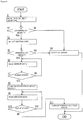
- system self-diagnosis is initially performed by the CPU of the flying object igniter 10 (step S1). In this case, whether or not a normal operation is achievable is diagnosed using an acceleration sensor or the like which measures an acceleration of the flying object.
- step S2 When the absence of abnormality is determined as a result of step S1 (YES in step S2), whether or not the ignition unit 11 is operable is detected by the above-described method using the ignition abnormality detection unit 21 (step S3). On the other hand, when the absence of abnormality is not determined as a result of step S1 (NO in step S2), the diagnosis unit 24 notifies the administrator or the like of an error (step S4) to end the process.
- step S5 When an abnormality is absent in the ignition unit 11 (YES in step S5) after step S3, the flight state detection unit 22 reads actual measurement data from the acceleration sensor or the like (step S6). On the other hand, when an abnormality is present in the ignition unit 11 (NO in step S5), the diagnosis unit 24 notifies the administrator or the like of an error (step S4) to end the process.
- step S7 When the flying object is in the flight state (YES in step S7) after step S6, the calculation unit 23 turns on the energizing circuit switch 25a (step S8). On the other hand, when the flying object is not in the flight state (NO in step S7), the flight state detection unit 22 returns to the processing of step S6. Note that the diagnosis unit 24 may notify the administrator or the like of an error before returning to the processing of step S6 when the flight state detection unit 22 detects an abnormality in the flight state of the flying object.
- step S8 the flight state detection unit 22 again continues reading the actual measurement data from the acceleration sensor (step S9). Subsequently, when the flying object is not in the flight state (NO in step S10), the calculation unit 23 turns off the energizing circuit switch 25a (step S11). On the other hand, when the flying object is in the flight state (YES in step S10), the flight state detection unit 22 returns to the processing of step S9.
- the operation state of the ignition unit 11 is detected by the ignition abnormality detection unit 21. Accordingly, whether or not the ignition unit 11 is normally operable is recognizable. In this manner, the operation of the ignition unit 11 can be guaranteed. It is therefore avoidable to activate a system of the safety device without checking whether or not the ignition unit 11 is operable. Furthermore, the calculation unit 23 compares the detection result obtained by the ignition abnormality detection unit 21 and the detection result obtained by the flight state detection unit 22 with the respective thresholds, and performs control for turning on the energizing circuit switch 25a based on a comparison result.
- the energizing circuit switch 25a is configured to be turned on when the flying object is determined to be in the flying state with the operation of the ignition unit 11 guaranteed. Accordingly, malfunction of the ignition unit 11 is avoidable. In the manner described above, reliability of the flying object igniter 10 in terms of safety can improve.
- the diagnosis unit 24 notifies the administrator or the like that an abnormality has been detected when the ignition abnormality detection unit 21 detects an abnormality in the ignition unit 11, or when the flight state detection unit 22 detects an abnormality in the flight state of the flying object. Accordingly, the administrator or the like can easily and immediately recognize the abnormality.
- the ignition abnormality detection unit 21 is constituted by a resistance detection device which supplies to the ignition unit 11 a weak current having a current value lower than a current value during normal operation, and detects a resistance value of the ignition unit 11. Accordingly, an abnormality of the ignition unit 11 is easily detectable by a simple configuration.
- the parachute or paraglider deploying device includes a pyro-actuator which propels a piston by gas pressure generated in accordance with an ignition operation of the flying object igniter 10.
- the parachute or paraglider deploying device may adopt such a configuration which includes an actuator (pyroactuator) and a parachute or a paraglider in a housing having one opened end, and directly pushes out the parachute or the paraglider by a propelling force of the piston of the actuator to deploy the parachute or the paraglider.
- an actuator pyroactuator
- a parachute or a paraglider in a housing having one opened end, and directly pushes out the parachute or the paraglider by a propelling force of the piston of the actuator to deploy the parachute or the paraglider.
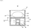
- a parachute or paraglider deploying device 90 includes an actuator 88 and a parachute or paraglider 86.
- the actuator 88 includes a flying object igniter 84 which is similar to the flying object igniter 10 described above and has a cup-shaped case 85 storing an ignition charge (not shown), a piston 81 having a recess 82 and a piston head 83 formed integrally with the recess 82, and a housing 80 having a bottomed cylindrical shape, housing the piston 81, and regulating a propelling direction of the piston 81.
- the parachute or paraglider 86 is housed in the housing 80 while disposed on the piston head 83, and constitutes a so-called parachute.
- the parachute or paraglider 86 can be directly pushed out and deployed in accordance with propelling by the piston 81. Note that the open end of the housing 80 is closed by a cover 87 in an initial state. The cover 87 is separated from the open end by being pushed by the parachute or paraglider 86.
- the piston 81 is propelled by gas pressure generated by the ignition operation of the flying object igniter 84 when an abnormality is detected by an abnormality detection unit (not shown) such as an acceleration sensor. In this manner, the parachute or paraglider 86 can be directly pushed out and deployed by the propelling force of the piston 81.
- the parachute or paraglider deploying device 90 further includes a component detection unit 63 which detects the presence or absence and abnormality of the parachute or paraglider 86, and a notification unit 64 which notifies the administrator or the like of the absence or abnormality of the parachute or paraglider 86 when the component detection unit 63 detects the absence or abnormality of the parachute or paraglider 86.
- the component detection unit 63 is constituted by an optical sensor.
- FIG. 5 is a diagram showing an example of a flying object to which the parachute or paraglider deploying device 90 of FIG. 4 is applied.
- a flying object 200 includes an airframe 201, one or more propelling mechanisms (for example, propellers) 202 which are coupled to the airframe 201 to propel the airframe 201, a plurality of legs 203 provided on a lower part of the airframe 201, and a flight control unit (not shown).
- the parachute or paraglider deploying device 50 is provided on the airframe 201.
- the parachute or paraglider deploying device 90 includes the flying object igniter 84.
- the operation of the ignition unit 11 can be guaranteed, and malfunction of the ignition unit 11 can be prevented similarly to the above. Accordingly, reliability of the parachute or paraglider deploying device 90 in terms of safety can improve.
- the notification unit 64 notifies the administrator or the like that the abnormality or the like has been detected. Accordingly, the administrator or the like can easily and immediately recognize the abnormality.
- flying objects 300 and 400 each including an airbag device to which the flying object igniter of the present embodiment is applied.
- parts in FIG. 6 referred to below and given last two digits identical to corresponding digits in FIG. 5 are similar to the corresponding parts described in FIG. 5 unless specified otherwise. Accordingly, description of these parts is not repeated.
- parts in FIG. 7 referred to below and given last two digits identical to corresponding digits in FIGS. 5 and 6 are similar to the corresponding parts described in FIGS. 5 and 6 unless specified otherwise. Accordingly, description of these parts is not repeated.
- the flying object 300 includes an airbag device 310 which inflates an airbag 311 by gas pressure generated by an ignition operation of a flying object igniter similar to the flying object igniter 10 described above.
- the airbag device 310 is provided on an airframe 301 facing a parachute or paraglider deploying device 190 provided on a lower part of the airframe 301 in a normal posture.
- the flying object igniter is operated in response to an operation signal transmitted from a control unit mounted on the flying object (a computer having a CPU, a ROM, a RAM, and the like) to operate the flying object igniter when (1) an abnormality detection unit (not shown) such as an acceleration sensor detects a predetermined acceleration or higher (for example, a preset acceleration at which falling is assumed), or when (2) a reception unit mounted on the flying object is in a state unable to receive a control signal from a transmission unit of a control device for a predetermined time or longer, for example.
- the airbag 311 is inflated by gas pressure thus generated. In this manner, obstacles and loads, especially pedestrians can be protected at the time of falling.
- an airbag device 410 of the flying object 400 may be provided on an airframe 401 facing a parachute or paraglider deploying device 290 provided on an upper part of the airframe 401 in a normal posture.
- the flying object 400 includes a device (not shown) provided on a lower part of the airframe 401 in a normal posture.
- a component detection unit which detects the presence or absence and abnormality of the airbags 311 and 411, and a notification unit which notifies the administrator or the like of the absence or abnormality of the airbags 311 and 411 when the absence or abnormality of the airbags 311 and 411 is detected by the component detection unit may be further provided similarly to the configuration of FIG. 4 described above.
- the airbag devices 310 and 410 each include the flying object igniter of the present embodiment.
- the operation of the ignition unit 11 can be guaranteed, and malfunction of the ignition unit 11 can be prevented similarly to the above. Accordingly, reliability of the airbag devices 310 and 410 in terms of safety can improve.
- the notification unit notifies the administrator or the like that the abnormality or the like has been detected. Accordingly, the administrator or the like can easily and immediately recognize the abnormality.
- the attachment positions of the above-described airbag devices 310 and 410 which are shown in FIGS. 6 and 7 and configured to protect persons and objects, are not limited to the positions shown in FIGS. 6 and 7 .
- the positions of the airbag devices 310 and 410 on the surface of the airframe may be any positions as long as the airbags 311 and 411 can be deployed and inflated to protect persons and objects.
- the flying object igniter 84 has been described in the above embodiment as an example of the flying object operating device, the present invention is not limited to this example. A following example may be adopted as another example of the flying object operating device. Note that parts in FIG. 8 referred to below and given last two digits identical to corresponding digits in FIG. 4 are similar to the corresponding parts described in FIG. 4 unless specified otherwise. Accordingly, description of these parts is not repeated.
- a parachute or paraglider deploying device 390 includes a flying object operating device 220, and a pushing portion 194 which is provided inside a housing 180 having a bottomed cylindrical shape, and includes a support plate 196 for supporting a parachute or paraglider 186, and a spring 195 having one end connected to a lower surface of the support plate 196.
- An openable cover 191 which can be opened is provided at an open end of the housing 180. Apart of the parachute or paraglider 186 is in contact with a lower surface of the openable cover 191, and the other part is supported by the support plate 196 and housed in the housing 180 while urged upward by the spring 195.
- the openable cover 191 in an initial state is closed by a lever portion (locking unit) 192 of an operating unit 210 by being locked.
- a lower surface of the lever portion 192 is connected to one end of a rotation shaft (not shown, and corresponding to a rotating shaft extending in a substantially vertical direction (the up-down direction in the sheet surface of FIG.
- the flying object operating device 220 includes an abnormality detection unit (not shown) which detects an operating state of the operating unit 210, a flight state detection unit (not shown) which is similar to the flight state detection unit 22 of FIG.
- an energizing circuit (not shown) which has an energizing circuit switch for operating the operating unit 210, and a calculation unit (not shown) which compares a detection result obtained by the abnormality detection unit and a detection result obtained by the flight state detection unit with respective thresholds set beforehand, and turns on the energizing circuit switch in accordance with a comparison result.
- the abnormality detection unit which detects the operating state of the operating unit 210 detects an operating state of the driving unit 193.
- the abnormality detection unit detects whether or not the driving unit 193 is operable.
- the abnormality detection unit detects an abnormality of the driving unit 193 based on an electric circuit resistance value.
- the electric circuit resistance value is determined by a structure of an electric circuit (a circuit length, a material constituting the circuit, a thickness of the circuit, and the like). A range of the resistance value when the electric circuit normally functions is determined in correspondence with this structure.
- the abnormality detection unit determines that the operating state of the driving unit 193 is abnormal when the electric circuit resistance value of the driving unit 193 is out of the resistance value range.
- a state where the electric circuit resistance value is ⁇ indicates that the electric circuit of the driving unit 193 is disconnected.
- the pushing portion 194 and the parachute or paraglider 186 constitute a moving unit capable of moving (opening) the openable cover 191 from the opening of the housing 180 when the locking by the lever portion 192 is released.
- the lever portion 192 is rotated to a predetermined position by the driving of the driving unit 193 when an abnormality is detected by an abnormality detection unit such as an acceleration sensor.
- an abnormality detection unit such as an acceleration sensor.
- the locking (hooking) of the openable cover 191 by the lever portion 192 is released, and the openable cover 191 is opened.
- the spring 195 of the pushing portion 194 extends, and the parachute or paraglider 186 is pushed out by an extension force thus generated. Consequently, the openable cover 191 is opened, and the parachute or paraglider 186 ejected to the outside is deployed.
- the flying object operating device 220 is also configured to prevent activation of a system of the safety device without checking whether or not the operating unit 210 is operable, and turn on the energizing circuit switch when the flying object is determined to be in the flying state with the operation of the operating unit 210 guaranteed. Accordingly, malfunction of the operating unit 210 can be prevented. In this manner, reliability in terms of safety can improve.
- Propelling force generated by gas pressure, wind pressure, or the like
- elastic bodies such as rubber to push out (eject) the parachute or paraglider 186 to the outside of the housing and open the cover.
- the acceleration sensor is not limited to this example.
- other sensors such as a gyro sensor, a pressure sensor, a laser sensor, and an ultrasonic sensor, or wireless communication using signals from GNSS (Global Navigation Satellite System) or a drone or signals from an operator may be adopted.
- GNSS Global Navigation Satellite System
- the ignition abnormality detection unit 21, the flight state detection unit 22, the calculation unit 23, and the diagnosis unit 24 are functionally implemented by software in the above embodiment, the present invention is not limited to this example. These units may be constituted by hardware.
- the pushing portion uses a spring in the above-described modification
- the present invention is not limited to this example. Any types such as rubber and other elastic bodies may be adopted instead of the spring as long as an urging force can be generated.
- the flying object igniter may have a functional configuration shown in FIG. 9 instead of the functional configuration shown in FIG. 2 .
- the flying object igniter of the present modification includes a diagnosis unit 124 in an energizing circuit 125 instead of the diagnosis unit 24 in the control unit 20 of the above embodiment, and further includes a user interface 126.
- the flying object igniter of the present modification includes a sensor unit 127 containing various sensors such as an acceleration sensor and an altitude sensor, a storage unit 128 capable of storing data obtained by the sensor unit 127, and various data such as data obtained when an abnormality is detected, and an auxiliary power source 129 constituting an auxiliary power source for a power source of a flying object body.
- the user interface 126 includes a determination start switch 126a operated by a user when determining beforehand whether or not an ignition abnormality is present before starting an operation, and an indicator lamp 126b indicating a determination result of the determination start switch 126a.
- the indicator lamp 126b is a lighting device such as an LED, and lights in yellow during determination, in blue when an abnormality is absent (indication of safety), and in red when an abnormality is present (indication of error). Note that the operation of the flying object is disabled until cancellation of an abnormality when the abnormality is present before the operation of the flying object.
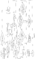
- system self-diagnosis is initially performed by the CPU of the flying object igniter having the functional configuration shown in FIG. 9 (step S1). Performed in this case are diagnosis of whether an abnormality is absent in the circuit, diagnosis of whether a normal operation is achievable using an acceleration sensor measuring an acceleration of the flying object or the like, and diagnosis of whether an ignition unit 111 is operable, for example.
- step P2 determines whether or not the determination start switch is in the ON state (whether or not the administrator or the like has operated the determination start switch 126a) (step P3).
- step P3 determines whether or not the determination start switch is in the ON state (whether or not the administrator or the like has operated the determination start switch 126a) (step P3).
- the diagnosis unit 124 transmits an error signal to the user interface 126 to notify the administrator or the like of an error, and causes the indicator lamp 126b to light in red (step P4). Thereafter, the process ends.
- the flight state detection unit 122 When the determination start switch is in the ON state (YES in step P3), the flight state detection unit 122 performs zero point correction for altitude information associated with the flying object, and information indicating the flight state of the flying object, such as a descent speed and a propeller rotation speed of a propelling mechanism (for example, resetting the condition that the flying object is in contact with the ground surface (at altitude 0) at the current altitude, or resetting the above-described propeller speed and descent speed to 0) (step P5).
- the ignition abnormality detection unit 121 may transmit a safety signal to the user interface 126 and cause the indicator lamp 126b to light in blue to notify the administrator or the like that there has been no abnormality.
- the flight state detection unit 122 reads actual measurement data, such as data obtained by the acceleration sensor, from the sensor unit 127 (step P6), and then determines whether or not the flight state of the flying object is equal to or higher than a predetermined condition (step P7). For example, when the flight state meets all of following conditions: a certain altitude (for example, 1 m) or higher of the flying object, a certain speed (for example, 1000 rpm) or higher of the propeller speed of the propelling mechanism, and a certain speed (for example, 5 m/s) or lower of the descent speed of the flying object (YES in step P7), the calculation unit 123 turns on the energizing circuit switch 125a (step P8).
- the flight state detection unit 122 returns to the processing of step P6.
- the diagnosis unit 124 may notify the administrator or the like of an error when the flight state detection unit 122 detects an abnormality in the flight state of the flying object before returning to the processing of step P6.
- step P8 the flight state detection unit 122 again continues reading the measured data obtained by the acceleration sensor (step P9), and then determines whether or not an abnormality is present in the flying object (step P10).
- the flight state detection unit 122 determines whether the flying object is free-falling (step P11).
- the flight state detection unit 122 determines whether or not the inclination of the flying object is a predetermined value or larger (step P12).
- the flight state detection unit 122 determines whether or not the remaining amount of the power source of the flying object is a predetermined value (for example, 5% of the total amount) or smaller (step P13).
- the flight state detection unit 122 determines whether or not the descent speed of the flying object is a predetermined value (for example, 10 m/s) or higher (step P14).
- the flight state detection unit 122 determines whether or not a signal for ending the abnormality determination has been received (step P15).
- the signal for ending the abnormality determination herein is received when the signal is transmitted wirelessly from the administrator or the like, or transmitted based on self-determination by the CPU (for example, transmitted when the altitude of the flying object reaches 2 m or lower).
- the self-determination by the CPU detects that the current state is not the flight state by adopting other sensors such as an acceleration sensor, a gyro sensor, a pressure sensor, a laser sensor, and an ultrasonic sensor, or wireless communication using signals from GNSS or a drone or signals from an operator.
- step P15 When the signal for ending the abnormality determination has not been received for a predetermined time or longer (NO in step P15), the process returns to step P9.
- the calculation unit 123 turns off the energizing circuit switch 125a (step P18) to end the process. Note that the calculation unit 123 may turn off the energizing circuit switch 125a only when the flying object is at a predetermined altitude or lower in this step.
- the flight state detection unit 122 outputs and transmits an operation signal for operating the igniter 111 to eject the parachute or paraglider of the flying object operating device (step P16) when determining that an abnormality is present in the flying object (YES in step P10), determining that the flying object is free-falling (YES in step P11), determining that the inclination of the flying object is a predetermined value or larger (YES in step P12), determining that (YES in step P13), and determining that (YES in step P14).
- the flight state detection unit 122 stores data associated with the flying object before and after the output of the signal in the storage unit 128 (step P17). Thereafter, the present process ends.
- a flowchart of FIG. 11 is different from the flowchart shown in FIG. 10 in that processing for stopping a drive system of the flying object (for example, a motor rotating a propeller which generates buoyancy) (step T16) is executed before outputting an ejection signal (step T17).
- steps T1 to T15 and step T19 sequentially execute processing similar to the processing of steps P1 to P15 and step S18 in FIG. 10
- steps T17 and T18 execute processing similar to the processing of steps P16 and P17 in FIG. 10 . Accordingly, description of these steps is not repeated.
- Described with reference to a flowchart of FIG. 12 will be an operation of a flying object igniter having the functional configuration shown in FIG. 9 , and further including an audio output unit (not shown).
- the flowchart of FIG. 12 is different from the flowchart shown in FIG. 11 in that processing for causing the above-described audio output unit to output a sound to generate a warning to surroundings is executed (step Q19) after data before and after the output of the sound is stored (step Q18).
- steps Q1 to Q18 and step Q20 sequentially execute processing similar to the processing of steps T1 to T18 and step T19 in FIG. 11 . Accordingly, description of these steps is not repeated.
- an illumination output unit which generates a warning of light may be used instead of the audio output unit, or both the audio output unit and the illumination output unit may be used. The same applies to following modifications.
- a flowchart of FIG. 13 is different from the flowchart shown in FIG. 12 in that processing for determining whether or not the flying object has landed (step U20), and processing for separating the parachute (step U21) are executed after processing for causing the audio output unit to output a sound generating a warning to surroundings is performed (step U19).
- steps U1 to U19 and step U22 sequentially execute processing similar to the processing of steps U1 to U19 and step Q20 in FIG. 12 . Accordingly, description of these steps is not repeated.
- step U20 the flight state detection unit 122 executes processing for determining whether or not the flying object has landed based on altitude data and speed data detected by an altitude sensor, an acceleration sensor, and the like.
- step U20 is repeated.
- the parachute or paraglider (deployed object) deployed while connected to the flying object by a string-shaped connecting member or the like is separated from the flying object (step U21).
- step U21 separation of the parachute or paraglider from the flying object in step U21 is achieved by a cutting mechanism (not shown) which operates in accordance with a command signal from the flight state detection unit 122.
- Described with reference to a flowchart of FIG. 14 will be an operation of a flying object igniter having the functional configuration shown in FIG. 9 , and further including an audio output unit (not shown) and a transmission device (not shown).
- the flowchart of FIG. 14 is different from the flowchart shown in FIG. 13 in that a landing position of the flying object is transmitted from the above-described transmission device to a reception device of the administrator or the like, a control tower, or others (step V22) after processing for separating the parachute or the paraglider is performed (step V21).
- steps V1 to V21 and step V23 sequentially execute processing similar to the processing of steps U1 to U21 and step U22 of FIG. 13 . Accordingly, description of these steps is not repeated.
Landscapes
- Engineering & Computer Science (AREA)
- Aviation & Aerospace Engineering (AREA)
- Mechanical Engineering (AREA)
- Remote Sensing (AREA)
- General Engineering & Computer Science (AREA)
- Air Bags (AREA)
- Control Of Position, Course, Altitude, Or Attitude Of Moving Bodies (AREA)
- Emergency Lowering Means (AREA)
Applications Claiming Priority (2)
| Application Number | Priority Date | Filing Date | Title |
|---|---|---|---|
| JP2018052761 | 2018-03-20 | ||
| PCT/JP2019/011614 WO2019181989A1 (ja) | 2018-03-20 | 2019-03-19 | 飛行体用作動装置、飛行体用作動装置の誤動作防止方法、飛行体用推力発生装置、パラシュートまたはパラグライダーの展開装置、およびエアバッグ装置 |
Publications (3)
| Publication Number | Publication Date |
|---|---|
| EP3770068A1 true EP3770068A1 (de) | 2021-01-27 |
| EP3770068A4 EP3770068A4 (de) | 2021-12-15 |
| EP3770068B1 EP3770068B1 (de) | 2024-08-21 |
Family
ID=67987763
Family Applications (1)
| Application Number | Title | Priority Date | Filing Date |
|---|---|---|---|
| EP19770659.1A Active EP3770068B1 (de) | 2018-03-20 | 2019-03-19 | Flugobjektbetätigungsvorrichtung, verfahren zur verhinderung von fehlfunktionen der flugobjektbetätigungsvorrichtung, flugobjektschuberzeugungsvorrichtung, fallschirm- oder gleitschirmauslösevorrichtung und airbagvorrichtung |
Country Status (5)
| Country | Link |
|---|---|
| US (1) | US12122522B2 (de) |
| EP (1) | EP3770068B1 (de) |
| JP (1) | JP7191090B2 (de) |
| CN (1) | CN111801274B (de) |
| WO (1) | WO2019181989A1 (de) |
Families Citing this family (7)
| Publication number | Priority date | Publication date | Assignee | Title |
|---|---|---|---|---|
| JP7308724B2 (ja) * | 2019-10-31 | 2023-07-14 | 日本化薬株式会社 | 飛行体用安全装置 |
| FR3105779B1 (fr) * | 2019-12-27 | 2022-12-02 | Azur Drones | Dispositif et procédé de contrôle automatique de l’état de service d’un système de parachute d’un drone volant. |
| JP6857753B1 (ja) | 2020-01-15 | 2021-04-14 | 日本化薬株式会社 | 回路異常診断装置、電流発生装置、飛行体用被展開体射出装置、飛行体用エアバッグ装置、および、飛行体用切断装置 |
| US12252259B2 (en) | 2020-03-06 | 2025-03-18 | Nippon Kayaku Kabushiki Kaisha | Safety device, and flying body provided with safety device |
| MA51692A1 (fr) * | 2020-11-05 | 2022-05-31 | Univ Int Rabat | Système d’airbag pour la récupération des véhicules aériens sans pilote |
| US12012208B2 (en) * | 2020-12-23 | 2024-06-18 | Osmose Utilities Services, Inc. | Systems and methods for inspecting structures with an unmanned aerial vehicle |
| CN113104222B (zh) * | 2021-05-06 | 2022-04-29 | 北京理工大学 | 一种无人机用自主安全防摔装置及其控制方法 |
Family Cites Families (15)
| Publication number | Priority date | Publication date | Assignee | Title |
|---|---|---|---|---|
| JPH0961479A (ja) | 1995-08-23 | 1997-03-07 | Toyota Motor Corp | システムの故障検知装置 |
| JP2004217059A (ja) | 2003-01-15 | 2004-08-05 | Daicel Chem Ind Ltd | ガス発生器 |
| JP2014212479A (ja) * | 2013-04-19 | 2014-11-13 | ソニー株式会社 | 制御装置、制御方法及びコンピュータプログラム |
| IL229068A (en) * | 2013-10-24 | 2016-06-30 | Amir Tsaliah | Facility and method for rapid parachute deployment |
| CN110626510A (zh) | 2014-02-27 | 2019-12-31 | 深圳市大疆创新科技有限公司 | 撞击保护设备 |
| CN103895870B (zh) | 2014-03-18 | 2016-08-24 | 华南农业大学 | 一种用于多旋翼无人机的紧急伞降装置及方法 |
| US20160009392A1 (en) * | 2014-03-31 | 2016-01-14 | Sharper Shape Oy | Unmanned aerial vehicle and method for protecting payload |
| CN104058095B (zh) * | 2014-06-12 | 2016-06-29 | 深圳市哈博森科技有限公司 | 飞行器降落伞控制系统及方法 |
| JP6425969B2 (ja) * | 2014-10-29 | 2018-11-21 | ヤンマー株式会社 | ヘリコプター |
| WO2016182750A1 (en) * | 2015-04-28 | 2016-11-17 | SkyFallX, LLC | Autonomous safety and recovery system for unmanned aerial vehicles |
| ES2722325T3 (es) * | 2015-05-18 | 2019-08-09 | Boeing Co | Sistema y método de terminación de vuelo para vehículos aéreos |
| US10059459B2 (en) * | 2015-05-28 | 2018-08-28 | Kespry Inc. | Unmanned aerial vehicle recovery system |
| WO2017066649A1 (en) * | 2015-10-14 | 2017-04-20 | Flirtey Holdings, Inc. | Parachute deployment system for an unmanned aerial vehicle |
| US20180065745A1 (en) * | 2016-09-07 | 2018-03-08 | Flytrex Aviation Ltd. | Unmanned vehicles navigation termination system |
| US11046443B2 (en) * | 2017-11-07 | 2021-06-29 | Intel Corporation | Safety systems for unmanned vehicles |
-
2019
- 2019-03-19 US US16/981,298 patent/US12122522B2/en active Active
- 2019-03-19 JP JP2020507863A patent/JP7191090B2/ja active Active
- 2019-03-19 EP EP19770659.1A patent/EP3770068B1/de active Active
- 2019-03-19 WO PCT/JP2019/011614 patent/WO2019181989A1/ja not_active Ceased
- 2019-03-19 CN CN201980016766.XA patent/CN111801274B/zh active Active
Also Published As
| Publication number | Publication date |
|---|---|
| US12122522B2 (en) | 2024-10-22 |
| WO2019181989A1 (ja) | 2019-09-26 |
| CN111801274A (zh) | 2020-10-20 |
| CN111801274B (zh) | 2024-09-17 |
| JPWO2019181989A1 (ja) | 2021-03-11 |
| EP3770068B1 (de) | 2024-08-21 |
| US20210371114A1 (en) | 2021-12-02 |
| JP7191090B2 (ja) | 2022-12-16 |
| EP3770068A4 (de) | 2021-12-15 |
Similar Documents
| Publication | Publication Date | Title |
|---|---|---|
| EP3770068B1 (de) | Flugobjektbetätigungsvorrichtung, verfahren zur verhinderung von fehlfunktionen der flugobjektbetätigungsvorrichtung, flugobjektschuberzeugungsvorrichtung, fallschirm- oder gleitschirmauslösevorrichtung und airbagvorrichtung | |
| CN110709322B (zh) | 飞行体以及飞行体的控制方法 | |
| JP7089623B2 (ja) | 墜落検知装置、飛行体の墜落を検知する方法、パラシュートまたはパラグライダーの展開装置、およびエアバッグ装置 | |
| WO2018043116A1 (ja) | エアバッグ装置を備えた小型飛行体 | |
| US9004400B2 (en) | Method of controlling a buoyancy system for an aircraft, a buoyancy system implementing said method, and an aircraft | |
| EP3287366A1 (de) | Flugzeug mit einem notschwimmersystem | |
| CN114423681A (zh) | 针对具有可展开降落伞的飞行器的损害减轻 | |
| JP2020019463A (ja) | パラシュートまたはパラグライダーの展開装置およびこれを備えた飛行体 | |
| US20230373666A1 (en) | Safety device and flight vehicle | |
| EP3805099B1 (de) | Notlandevorrichtung | |
| JP7744837B2 (ja) | 飛行体用線状接続具、安全装置、安全装置を備えた飛行体、および、飛行体用線状接続具を用いた結び留め方法 | |
| US8800923B2 (en) | Method of activating protection means for protecting an occupant of an aircraft, and an aircraft implementing said method | |
| JP2026046499A (ja) | 安全装置、および、安全装置を備えた飛行体 | |
| JP2026051961A (ja) | 安全装置、および、安全装置を備えた飛行体 | |
| JP2023182484A (ja) | 安全装置、および、安全装置を備えた飛行体 |
Legal Events
| Date | Code | Title | Description |
|---|---|---|---|
| STAA | Information on the status of an ep patent application or granted ep patent |
Free format text: STATUS: THE INTERNATIONAL PUBLICATION HAS BEEN MADE |
|
| PUAI | Public reference made under article 153(3) epc to a published international application that has entered the european phase |
Free format text: ORIGINAL CODE: 0009012 |
|
| STAA | Information on the status of an ep patent application or granted ep patent |
Free format text: STATUS: REQUEST FOR EXAMINATION WAS MADE |
|
| 17P | Request for examination filed |
Effective date: 20201016 |
|
| AK | Designated contracting states |
Kind code of ref document: A1 Designated state(s): AL AT BE BG CH CY CZ DE DK EE ES FI FR GB GR HR HU IE IS IT LI LT LU LV MC MK MT NL NO PL PT RO RS SE SI SK SM TR |
|
| AX | Request for extension of the european patent |
Extension state: BA ME |
|
| DAV | Request for validation of the european patent (deleted) | ||
| DAX | Request for extension of the european patent (deleted) | ||
| A4 | Supplementary search report drawn up and despatched |
Effective date: 20211112 |
|
| RIC1 | Information provided on ipc code assigned before grant |
Ipc: F42B 3/12 20060101ALI20211108BHEP Ipc: B64D 45/00 20060101ALI20211108BHEP Ipc: B64D 17/72 20060101ALI20211108BHEP Ipc: B64D 17/00 20060101ALI20211108BHEP Ipc: B64C 39/02 20060101ALI20211108BHEP Ipc: B64C 31/036 20060101ALI20211108BHEP Ipc: B64D 25/00 20060101AFI20211108BHEP |
|
| STAA | Information on the status of an ep patent application or granted ep patent |
Free format text: STATUS: EXAMINATION IS IN PROGRESS |
|
| 17Q | First examination report despatched |
Effective date: 20230413 |
|
| GRAP | Despatch of communication of intention to grant a patent |
Free format text: ORIGINAL CODE: EPIDOSNIGR1 |
|
| STAA | Information on the status of an ep patent application or granted ep patent |
Free format text: STATUS: GRANT OF PATENT IS INTENDED |
|
| INTG | Intention to grant announced |
Effective date: 20240402 |
|
| GRAS | Grant fee paid |
Free format text: ORIGINAL CODE: EPIDOSNIGR3 |
|
| GRAA | (expected) grant |
Free format text: ORIGINAL CODE: 0009210 |
|
| STAA | Information on the status of an ep patent application or granted ep patent |
Free format text: STATUS: THE PATENT HAS BEEN GRANTED |
|
| AK | Designated contracting states |
Kind code of ref document: B1 Designated state(s): AL AT BE BG CH CY CZ DE DK EE ES FI FR GB GR HR HU IE IS IT LI LT LU LV MC MK MT NL NO PL PT RO RS SE SI SK SM TR |
|
| REG | Reference to a national code |
Ref country code: GB Ref legal event code: FG4D |
|
| REG | Reference to a national code |
Ref country code: CH Ref legal event code: EP |
|
| REG | Reference to a national code |
Ref country code: IE Ref legal event code: FG4D |
|
| REG | Reference to a national code |
Ref country code: DE Ref legal event code: R096 Ref document number: 602019057436 Country of ref document: DE |
|
| REG | Reference to a national code |
Ref country code: LT Ref legal event code: MG9D |
|
| REG | Reference to a national code |
Ref country code: NL Ref legal event code: MP Effective date: 20240821 |
|
| PG25 | Lapsed in a contracting state [announced via postgrant information from national office to epo] |
Ref country code: NO Free format text: LAPSE BECAUSE OF FAILURE TO SUBMIT A TRANSLATION OF THE DESCRIPTION OR TO PAY THE FEE WITHIN THE PRESCRIBED TIME-LIMIT Effective date: 20241121 |
|
| REG | Reference to a national code |
Ref country code: AT Ref legal event code: MK05 Ref document number: 1715287 Country of ref document: AT Kind code of ref document: T Effective date: 20240821 |
|
| PG25 | Lapsed in a contracting state [announced via postgrant information from national office to epo] |
Ref country code: NL Free format text: LAPSE BECAUSE OF FAILURE TO SUBMIT A TRANSLATION OF THE DESCRIPTION OR TO PAY THE FEE WITHIN THE PRESCRIBED TIME-LIMIT Effective date: 20240821 Ref country code: GR Free format text: LAPSE BECAUSE OF FAILURE TO SUBMIT A TRANSLATION OF THE DESCRIPTION OR TO PAY THE FEE WITHIN THE PRESCRIBED TIME-LIMIT Effective date: 20241122 Ref country code: PL Free format text: LAPSE BECAUSE OF FAILURE TO SUBMIT A TRANSLATION OF THE DESCRIPTION OR TO PAY THE FEE WITHIN THE PRESCRIBED TIME-LIMIT Effective date: 20240821 Ref country code: FI Free format text: LAPSE BECAUSE OF FAILURE TO SUBMIT A TRANSLATION OF THE DESCRIPTION OR TO PAY THE FEE WITHIN THE PRESCRIBED TIME-LIMIT Effective date: 20240821 Ref country code: PT Free format text: LAPSE BECAUSE OF FAILURE TO SUBMIT A TRANSLATION OF THE DESCRIPTION OR TO PAY THE FEE WITHIN THE PRESCRIBED TIME-LIMIT Effective date: 20241223 |
|
| PG25 | Lapsed in a contracting state [announced via postgrant information from national office to epo] |
Ref country code: BG Free format text: LAPSE BECAUSE OF FAILURE TO SUBMIT A TRANSLATION OF THE DESCRIPTION OR TO PAY THE FEE WITHIN THE PRESCRIBED TIME-LIMIT Effective date: 20240821 |
|
| PG25 | Lapsed in a contracting state [announced via postgrant information from national office to epo] |
Ref country code: LV Free format text: LAPSE BECAUSE OF FAILURE TO SUBMIT A TRANSLATION OF THE DESCRIPTION OR TO PAY THE FEE WITHIN THE PRESCRIBED TIME-LIMIT Effective date: 20240821 |
|
| PG25 | Lapsed in a contracting state [announced via postgrant information from national office to epo] |
Ref country code: AT Free format text: LAPSE BECAUSE OF FAILURE TO SUBMIT A TRANSLATION OF THE DESCRIPTION OR TO PAY THE FEE WITHIN THE PRESCRIBED TIME-LIMIT Effective date: 20240821 Ref country code: IS Free format text: LAPSE BECAUSE OF FAILURE TO SUBMIT A TRANSLATION OF THE DESCRIPTION OR TO PAY THE FEE WITHIN THE PRESCRIBED TIME-LIMIT Effective date: 20241221 |
|
| PG25 | Lapsed in a contracting state [announced via postgrant information from national office to epo] |
Ref country code: HR Free format text: LAPSE BECAUSE OF FAILURE TO SUBMIT A TRANSLATION OF THE DESCRIPTION OR TO PAY THE FEE WITHIN THE PRESCRIBED TIME-LIMIT Effective date: 20240821 |
|
| PG25 | Lapsed in a contracting state [announced via postgrant information from national office to epo] |
Ref country code: RS Free format text: LAPSE BECAUSE OF FAILURE TO SUBMIT A TRANSLATION OF THE DESCRIPTION OR TO PAY THE FEE WITHIN THE PRESCRIBED TIME-LIMIT Effective date: 20241121 Ref country code: ES Free format text: LAPSE BECAUSE OF FAILURE TO SUBMIT A TRANSLATION OF THE DESCRIPTION OR TO PAY THE FEE WITHIN THE PRESCRIBED TIME-LIMIT Effective date: 20240821 |
|
| PG25 | Lapsed in a contracting state [announced via postgrant information from national office to epo] |
Ref country code: RS Free format text: LAPSE BECAUSE OF FAILURE TO SUBMIT A TRANSLATION OF THE DESCRIPTION OR TO PAY THE FEE WITHIN THE PRESCRIBED TIME-LIMIT Effective date: 20241121 Ref country code: PT Free format text: LAPSE BECAUSE OF FAILURE TO SUBMIT A TRANSLATION OF THE DESCRIPTION OR TO PAY THE FEE WITHIN THE PRESCRIBED TIME-LIMIT Effective date: 20241223 Ref country code: PL Free format text: LAPSE BECAUSE OF FAILURE TO SUBMIT A TRANSLATION OF THE DESCRIPTION OR TO PAY THE FEE WITHIN THE PRESCRIBED TIME-LIMIT Effective date: 20240821 Ref country code: NO Free format text: LAPSE BECAUSE OF FAILURE TO SUBMIT A TRANSLATION OF THE DESCRIPTION OR TO PAY THE FEE WITHIN THE PRESCRIBED TIME-LIMIT Effective date: 20241121 Ref country code: NL Free format text: LAPSE BECAUSE OF FAILURE TO SUBMIT A TRANSLATION OF THE DESCRIPTION OR TO PAY THE FEE WITHIN THE PRESCRIBED TIME-LIMIT Effective date: 20240821 Ref country code: LV Free format text: LAPSE BECAUSE OF FAILURE TO SUBMIT A TRANSLATION OF THE DESCRIPTION OR TO PAY THE FEE WITHIN THE PRESCRIBED TIME-LIMIT Effective date: 20240821 Ref country code: IS Free format text: LAPSE BECAUSE OF FAILURE TO SUBMIT A TRANSLATION OF THE DESCRIPTION OR TO PAY THE FEE WITHIN THE PRESCRIBED TIME-LIMIT Effective date: 20241221 Ref country code: HR Free format text: LAPSE BECAUSE OF FAILURE TO SUBMIT A TRANSLATION OF THE DESCRIPTION OR TO PAY THE FEE WITHIN THE PRESCRIBED TIME-LIMIT Effective date: 20240821 Ref country code: GR Free format text: LAPSE BECAUSE OF FAILURE TO SUBMIT A TRANSLATION OF THE DESCRIPTION OR TO PAY THE FEE WITHIN THE PRESCRIBED TIME-LIMIT Effective date: 20241122 Ref country code: FI Free format text: LAPSE BECAUSE OF FAILURE TO SUBMIT A TRANSLATION OF THE DESCRIPTION OR TO PAY THE FEE WITHIN THE PRESCRIBED TIME-LIMIT Effective date: 20240821 Ref country code: ES Free format text: LAPSE BECAUSE OF FAILURE TO SUBMIT A TRANSLATION OF THE DESCRIPTION OR TO PAY THE FEE WITHIN THE PRESCRIBED TIME-LIMIT Effective date: 20240821 Ref country code: BG Free format text: LAPSE BECAUSE OF FAILURE TO SUBMIT A TRANSLATION OF THE DESCRIPTION OR TO PAY THE FEE WITHIN THE PRESCRIBED TIME-LIMIT Effective date: 20240821 Ref country code: AT Free format text: LAPSE BECAUSE OF FAILURE TO SUBMIT A TRANSLATION OF THE DESCRIPTION OR TO PAY THE FEE WITHIN THE PRESCRIBED TIME-LIMIT Effective date: 20240821 |
|
| PG25 | Lapsed in a contracting state [announced via postgrant information from national office to epo] |
Ref country code: SM Free format text: LAPSE BECAUSE OF FAILURE TO SUBMIT A TRANSLATION OF THE DESCRIPTION OR TO PAY THE FEE WITHIN THE PRESCRIBED TIME-LIMIT Effective date: 20240821 Ref country code: DK Free format text: LAPSE BECAUSE OF FAILURE TO SUBMIT A TRANSLATION OF THE DESCRIPTION OR TO PAY THE FEE WITHIN THE PRESCRIBED TIME-LIMIT Effective date: 20240821 Ref country code: RO Free format text: LAPSE BECAUSE OF FAILURE TO SUBMIT A TRANSLATION OF THE DESCRIPTION OR TO PAY THE FEE WITHIN THE PRESCRIBED TIME-LIMIT Effective date: 20240821 |
|
| PG25 | Lapsed in a contracting state [announced via postgrant information from national office to epo] |
Ref country code: EE Free format text: LAPSE BECAUSE OF FAILURE TO SUBMIT A TRANSLATION OF THE DESCRIPTION OR TO PAY THE FEE WITHIN THE PRESCRIBED TIME-LIMIT Effective date: 20240821 |
|
| PG25 | Lapsed in a contracting state [announced via postgrant information from national office to epo] |
Ref country code: CZ Free format text: LAPSE BECAUSE OF FAILURE TO SUBMIT A TRANSLATION OF THE DESCRIPTION OR TO PAY THE FEE WITHIN THE PRESCRIBED TIME-LIMIT Effective date: 20240821 |
|
| PG25 | Lapsed in a contracting state [announced via postgrant information from national office to epo] |
Ref country code: IT Free format text: LAPSE BECAUSE OF FAILURE TO SUBMIT A TRANSLATION OF THE DESCRIPTION OR TO PAY THE FEE WITHIN THE PRESCRIBED TIME-LIMIT Effective date: 20240821 Ref country code: SK Free format text: LAPSE BECAUSE OF FAILURE TO SUBMIT A TRANSLATION OF THE DESCRIPTION OR TO PAY THE FEE WITHIN THE PRESCRIBED TIME-LIMIT Effective date: 20240821 |
|
| REG | Reference to a national code |
Ref country code: DE Ref legal event code: R097 Ref document number: 602019057436 Country of ref document: DE |
|
| PLBE | No opposition filed within time limit |
Free format text: ORIGINAL CODE: 0009261 |
|
| STAA | Information on the status of an ep patent application or granted ep patent |
Free format text: STATUS: NO OPPOSITION FILED WITHIN TIME LIMIT |
|
| 26N | No opposition filed |
Effective date: 20250522 |
|
| PG25 | Lapsed in a contracting state [announced via postgrant information from national office to epo] |
Ref country code: SE Free format text: LAPSE BECAUSE OF FAILURE TO SUBMIT A TRANSLATION OF THE DESCRIPTION OR TO PAY THE FEE WITHIN THE PRESCRIBED TIME-LIMIT Effective date: 20240821 |
|
| PG25 | Lapsed in a contracting state [announced via postgrant information from national office to epo] |
Ref country code: MC Free format text: LAPSE BECAUSE OF FAILURE TO SUBMIT A TRANSLATION OF THE DESCRIPTION OR TO PAY THE FEE WITHIN THE PRESCRIBED TIME-LIMIT Effective date: 20240821 |
|
| REG | Reference to a national code |
Ref country code: CH Ref legal event code: H13 Free format text: ST27 STATUS EVENT CODE: U-0-0-H10-H13 (AS PROVIDED BY THE NATIONAL OFFICE) Effective date: 20251024 |
|
| PG25 | Lapsed in a contracting state [announced via postgrant information from national office to epo] |
Ref country code: LU Free format text: LAPSE BECAUSE OF NON-PAYMENT OF DUE FEES Effective date: 20250319 |
|
| GBPC | Gb: european patent ceased through non-payment of renewal fee |
Effective date: 20250319 |
|
| REG | Reference to a national code |
Ref country code: BE Ref legal event code: MM Effective date: 20250331 |
|
| PG25 | Lapsed in a contracting state [announced via postgrant information from national office to epo] |
Ref country code: GB Free format text: LAPSE BECAUSE OF NON-PAYMENT OF DUE FEES Effective date: 20250319 |
|
| PG25 | Lapsed in a contracting state [announced via postgrant information from national office to epo] |
Ref country code: BE Free format text: LAPSE BECAUSE OF NON-PAYMENT OF DUE FEES Effective date: 20250331 |
|
| PG25 | Lapsed in a contracting state [announced via postgrant information from national office to epo] |
Ref country code: CH Free format text: LAPSE BECAUSE OF NON-PAYMENT OF DUE FEES Effective date: 20250331 |
|
| PG25 | Lapsed in a contracting state [announced via postgrant information from national office to epo] |
Ref country code: IE Free format text: LAPSE BECAUSE OF NON-PAYMENT OF DUE FEES Effective date: 20250319 |
|
| PGFP | Annual fee paid to national office [announced via postgrant information from national office to epo] |
Ref country code: DE Payment date: 20260128 Year of fee payment: 8 |
|
| PGFP | Annual fee paid to national office [announced via postgrant information from national office to epo] |
Ref country code: FR Payment date: 20260209 Year of fee payment: 8 |