EP3770310B1 - Métier à tisser circulaire à trajectoire périphérique - Google Patents
Métier à tisser circulaire à trajectoire périphérique Download PDFInfo
- Publication number
- EP3770310B1 EP3770310B1 EP20187472.4A EP20187472A EP3770310B1 EP 3770310 B1 EP3770310 B1 EP 3770310B1 EP 20187472 A EP20187472 A EP 20187472A EP 3770310 B1 EP3770310 B1 EP 3770310B1
- Authority
- EP
- European Patent Office
- Prior art keywords
- thread
- warp
- guide
- weaving
- circular
- Prior art date
- Legal status (The legal status is an assumption and is not a legal conclusion. Google has not performed a legal analysis and makes no representation as to the accuracy of the status listed.)
- Active
Links
Images





Classifications
-
- D—TEXTILES; PAPER
- D03—WEAVING
- D03D—WOVEN FABRICS; METHODS OF WEAVING; LOOMS
- D03D37/00—Circular looms
-
- D—TEXTILES; PAPER
- D03—WEAVING
- D03C—SHEDDING MECHANISMS; PATTERN CARDS OR CHAINS; PUNCHING OF CARDS; DESIGNING PATTERNS
- D03C13/00—Shedding mechanisms not otherwise provided for
-
- D—TEXTILES; PAPER
- D03—WEAVING
- D03D—WOVEN FABRICS; METHODS OF WEAVING; LOOMS
- D03D27/00—Woven pile fabrics
- D03D27/02—Woven pile fabrics wherein the pile is formed by warp or weft
-
- D—TEXTILES; PAPER
- D03—WEAVING
- D03D—WOVEN FABRICS; METHODS OF WEAVING; LOOMS
- D03D49/00—Details or constructional features not specially adapted for looms of a particular type
- D03D49/52—Shuttle boxes
-
- D—TEXTILES; PAPER
- D03—WEAVING
- D03D—WOVEN FABRICS; METHODS OF WEAVING; LOOMS
- D03D51/00—Driving, starting, or stopping arrangements; Automatic stop motions
- D03D51/02—General arrangements of driving mechanism
Definitions
- the invention relates to a circular weaving machine for weaving a weaving core with at least one shuttle which has a weft thread spool and is movable along a circular orbit around the weaving core.
- the well-known circular looms and weaving processes on circular looms are used to produce hollow-profile, tubular textile fabrics for, for example, fire hoses, water hoses, sacks or wheel rims, etc.
- a circular weaving machine of the type mentioned is known from the publication WO2017/190739 A1 known.
- One or more shuttles are moved along a circular orbit, guiding the weft thread in a circular path around the weaving core.
- Warp spool devices essentially have a warp thread spool with warp thread, a holder for the warp thread spool (warp spool holder) and a thread tensioning device.
- the warp bobbin devices are arranged in the immediate vicinity of a weaving plane which is radially enclosed by the circular orbit and is determined by the circumferential course of the weft thread around the weaving core.
- the warp spool devices are designed to be movable, with the path of the warp spool devices passing through the weaving plane in order to create a so-called dividing of the warp threads through their changing positioning and to create an interweaving with the weft thread.
- a separate thread guide or thread deflection of the warp threads is largely eliminated here.
- the transfer of the warp spool devices requires increased mechanical and control-technical effort.
- the rapid transfer of the warp spool devices and the rapid exit of the warp spool devices and their positioning devices from the weaving plane for passing the weft thread spool also mean a high level of design effort, with the transfer and exit times limiting the maximum possible speed of the weft thread spool.
- the warp spool devices are pivotably mounted on a peripheral housing, whereby the warp threads are alternately fed to the weaving core or the weaving plane in a fan-shaped manner by means of thread guide tubes that are connected to the pivotable warp spool devices, whereby the thread guide tubes cross the track for the shuttle's circulation in a direction that changes direction.
- the track is designed to be perforated for this purpose, in particular provided with wide slots for the thread guide tubes to pass through, whereby the thread guide tubes take up their changing positions along the slots.
- This circular weaving machine also requires a complex mechanical and control engineering design of the movement of the warp spool devices, whereby the speed of the shuttles is limited by the passage times of the thread guide tubes.
- the publication JP H01 168938 A disclosed a circular weaving machine with stationary warp spool devices and a guide device for the warp threads to be woven.
- the guide device consists of several deflection rollers, over which the warp threads are deflected at different angles, and furthermore of a belt construction with thread eyes, through which some or all of the warp threads are guided, whereby the belts can be moved alternately.
- the invention is based on the object of providing an improved circular weaving machine which eliminates the disadvantages of the prior art and which enables a higher productivity of weaving, in particular with simpler constructional means.
- a further task is to ensure improved functionality of the circular weaving machine for producing a hollow profile-like fabric, especially from sensitive fibers such as carbon fibers, of high weaving quality and variability.
- a circular weaving machine with the features of patent claim 1 or patent claim 2, according to which at least one guide device, designed to guide at least one of a warp thread spool of a warp spool device provided warp thread, which is movably arranged or designed outside a track plane enclosed by the outer circumference of the circular orbit, wherein the guided warp thread, crossing the track plane, passes through a recess in the circular orbit.
- One or more shuttles move with their weft thread spools along a circular orbit formed, for example, mechanically or electromagnetically, which determines the conveying or guiding line for the concentric conveying or guiding of the shuttle around the weaving core.
- the contactor(s) can move actively, e.g. preferably by means of its own electrically operated direct drive, along the orbit, or the contactor(s) can move passively, e.g. by means of an externally driven, rotatable mechanical driver or by means of an electromagnetic propulsion, transported and controlled along the orbit.
- the circular orbit is preferably arranged radially (perpendicular to the weaving axis) with respect to the axially directed weaving axis of the circular weaving machine, which gives the circular weaving machine a particularly narrow design.
- the circular orbit may be advantageous to arrange the circular orbit quasi-radially (at an angle other than 90° to the weaving axis).
- the radially outer circumference of the circular orbit forms the radial boundary of the track plane of the circular weaving machine, within which the shuttle(s) rotate with the weft thread.
- the axially outer width of the circular orbit forms the axial boundary of the track plane of the circular weaving machine, within which the shuttle(s) rotate with the weft thread.
- the outer boundary points of the circular orbit essentially describe the track plane as a circular disk.
- the warp spool devices with the warp thread spools are preferably located in the immediate vicinity of the web plane in order to be able to feed the warp threads to the weaving core over the shortest possible distances.
- the warp spool devices can be arranged stationary, e.g. fixed to a housing part of the circular weaving machine, or can be arranged in a movable manner at different positions in relation to the housing of the circular weaving machine.
- the guide device takes over the guidance and change positioning of the warp thread(s) (warp thread guide) between its provision by the warp spool device(s) and its weaving with the weft thread at a weaving point on the weaving core.
- the guide device acts separate from the design and function of the warp spool device(s).
- the weaving point refers to the variable point at which the warp threads are temporarily woven with the weft threads on the surface of the weaving core.
- the guide device is movably arranged outside the track plane or is designed to be movable in a fixed arrangement, wherein the movable guide device acts completely outside the track plane and only the guided warp thread crosses the track plane and thereby passes the associated recess of the circular orbit.
- the movable guide device can be fastened or movably mounted, for example, to a radial outer wall of the machine housing of the circular weaving machine or to the radial outer circumference of the circular orbit.
- a plurality of guide devices are arranged around the circumference of the circular orbit.
- warp spool devices which is assigned to a guide device
- these warp spool devices can be arranged next to each other, behind each other or above each other with respect to the direction of the thread guide of the warp threads towards the guide device.
- each warp thread is guided separately by a guide device.
- the warp threads drawn off the warp thread spools can be moved - without having to move the warp spool devices - in short distances, quickly and with little effort on both sides of the orbit and thus the track plane, whereby a warp thread guided by the guide device subsequently crosses the track plane in which the warp thread leaving the guide device, for example via a thread outlet, passes through a recess in the circular orbit assigned to the travel path of the thread outlet.
- the circular orbit thus has a number of openings or interruptions corresponding to the number of recesses provided.
- a guide device or a thread outlet of the guide device is spatially and functionally assigned to one or more recesses of the circular orbit. This allows individual warp threads to pass through one recess each or several warp threads to pass through one recess of the orbit with little or, ideally, no thread deflection. This allows the warp threads to be guided and passed through the recess of the orbit with particularly low wear and gentle thread care.
- the recesses of the orbit are preferably designed to be so narrow that only the warp thread(s) can just cross the orbit without contacting the orbit in order to avoid frictional wear of the warp threads.
- the recesses of the orbit for passing the warp threads are designed according to the guide device(s) or the thread outlet of the guide device(s) are arranged and extended in an aligned manner. This allows the warp thread to pass through the recess of the orbit without deflection.
- the recesses of the orbit can be designed, for example, as an elongated slot that breaks through the orbit locally (breakthrough) or, for example, as a continuous joint that separates the orbit at the point (interruption).
- the required thread tension of the warp threads is essentially maintained by the thread tensioning device of the warp bobbin devices, the positioning of which can be stationary and locally variable.
- the warp threads on both sides of the web plane can be alternately spread and fanned in opposite directions, for example, in order to form a warp thread ply while maintaining a high thread tension, whereby in the alternating positions of the warp threads outside the web plane, the passage of the shuttle(s) along the orbit is ensured, after which an undulation / interweaving of the warp threads with the weft thread running through the warp thread ply, which is drawn off from the weft thread spool of the shuttle carried along the orbit, takes place on the weaving core.
- weaving patterns can be formed on the weaving core to be woven.
- the geometric structure of the guide device(s) for the necessary changing positioning of the warp threads and the orbit can be designed in a structurally simplified manner and, on the other hand, the changing positions of the warp threads can be designed very close to the lateral, axial limitation of the track plane, so that the passage of the shuttles is just guaranteed without contact with the warp thread, after which the change of the warp thread positions and the circulation of the shuttles can take place more quickly.
- the weaving process can be accelerated and higher productivity achieved due to a structural and spatially reduced transport effort for changing and fanning the warp threads.
- the possibility of positioning the warp threads close to the orbit also causes the warp threads to run at a very flat angle (weaving angle) in relation to the extension of the web plane, so that the thread tension of the warp threads remains largely constant even through the close position change, to the advantage of high weaving quality.
- the contact- and deflection-free guidance and passage of the warp threads through the orbit ensures gentle use of the warp thread material, so that even sensitive thread materials, such as carbon fibers, can be processed well.
- the guide device(s) according to the invention only move the warp threads in narrow recesses of the orbit, this results in a
- the design of the circular weaving machine with thread guide tubes that swivel into the plane of the web has the further advantage that the shuttles can rotate in the orbit with less vibration and thus can rotate more quickly while maintaining a high thread tension, both of the warp threads and the weft thread, thus further improving the above-mentioned increase in productivity and quality.
- the circular weaving machine according to the invention is particularly suitable for weaving weaving cores with a cross-sectional geometry that changes in axial extension (in the direction of the axis of rotation of the weaving core (weaving core axis)), since the tightly woven threads can adhere to a changing weaving core contour in a contour-accurate manner.
- the weaving core is moved along the weaving axis of the circular loom in order to be able to weave the entire contour of the weaving core.
- the weaving point at which the warp threads are woven with the weft threads on the surface of the weaving core moves not only around the circumference of the rotating weaving core but also along its weaving core axis.
- the rotation axis of the weaving core (weaving core axis) is preferably designed to be congruent with the weaving axis of the circular weaving machine, so that the weaving core is moved in the direction of its rotation axis (weaving core axis) along the congruent weaving axis of the circular weaving machine.
- the rotation axis of the weaving core (weaving core axis) can also be arranged at an angle to the weaving axis of the circular weaving machine when weaving and moving the weaving core along the weaving axis of the circular weaving machine in order to be able to generate a variable angular position of the warp threads and the weft threads on the weaving core and thus a variable fabric tension.
- the circular weaving machine according to the invention is also suitable for the production of hollow profile-like, fiber-containing fabric preforms of fiber composite products, such as for the production of woven preforms for wheel rims made of fiber composite material.
- the movable guide device has at least one positioning part arranged or designed to be movable parallel to the weaving axis of the circular loom, with at least one thread guide element.
- the positioning part can be moved alternately relative to a base body of the guide device or relative to the machine housing of the circular weaving machine or relative to the circular orbit by means of a corresponding structural design of the guide device.
- the thread guide element of the guide device is provided for the actual steering and guidance of at least one warp thread during its alternating movement and guides a warp thread running off the warp thread spool or several warp threads running off warp thread spools, if necessary also with a thread deflection.
- the thread guide element can be connected to the positioning part or integrated into the positioning part.
- One or more thread guide elements can be arranged or formed on the positioning part of the guide device.
- the warp thread can also be guided and positioned by a positioning part of the guide device, which directly carries a warp thread spool.
- the guide device can also have several positioning parts, possibly with one or more thread guide elements for guiding and steering one or more warp threads.
- the thread guide element can be designed as a thread guide channel, as a thread guide groove or as a thread guide eyelet through which the warp thread is passed.
- the thread guide element can end with a thread outlet for the warp thread.
- a thread outlet is an outlet opening at the exit of the guided warp thread from the thread guide element of the positioning part.
- the thread guide element for moving the warp thread is arranged and designed on or in a movable positioning part of the guide device.
- the positioning part of the guide device can, for example, be a movable guide carriage on or in which one or more thread guide elements are arranged or formed.
- the positioning part can also be, for example, a movable or pivotable roller on which a thread guide groove (thread guide groove) is formed as a thread guide element in which the warp thread runs in a guided manner.
- a thread guide groove thread guide groove
- the positioning part and the guided warp thread are moved with at least one thread guide element parallel to the weaving axis of the circular loom. This results in the thread guide path of the warp threads being essentially perpendicular to the plane of the orbit.
- the recesses of the orbit are also designed to correspond to the path of the warp threads during their alternating movement, i.e. also to extend parallel to the weaving axis of the circular loom, the path and travel time of the warp threads to cross the track plane can be shortened, so that the changing speed of the warp threads and thus the orbital speed of the shuttles can be increased.
- the positioning part is designed to be linearly movable, whereby the guided warp thread can subsequently also be moved linearly.
- a linear movement of the positioning part can be implemented relatively easily in terms of construction and control technology.
- direct drives preferably linear drives
- the alternating movement of the positioning part can be generated and controlled by special switchable direct drives, e.g. by means of a rack or threaded rod acting in two directions.
- the guide and/or drive of the positioning part can also be magnetic and/or electromagnetic. If the warp thread carried along with the positioning part is also moved linearly, the associated linear guide of the warp thread also results in lower thread tension losses than with non-linear movements of the warp threads, which further improves the quality of the woven product.
- the linear mobility of the positioning part or the guided warp thread is designed in the axial direction along the weaving axis of the circular weaving machine.
- the travel path of the positioning part and thus the path of the warp threads is exactly perpendicular to the plane of the orbit.
- the positioning part of the guide device can, for example, be mounted in a movable manner using appropriate bearing elements.
- a guide carriage can be mounted on a base body of the guide device or on a component of the machine housing or directly on the outer circumference of the circular orbit by means of corresponding carriage bearing elements.
- the base body of the guide device can be arranged on a component of the machine housing or directly on the outer circumference of the circular orbit.
- the base body can be stationary and connected to the machine housing or the orbit or can be arranged so that it can move.
- One or more positioning parts can be assigned to a base body and are mounted so that they can move relative to this base body.
- the bearing element(s) for the mobile mounting of a positioning part, such as a guide carriage can be, for example, one or more longitudinally extending guide groove(s) of the base body or the component of the machine housing or the guide carriage, which are arranged in the direction of the intended axis of movement of the thread guide element and correspond to corresponding guide bolts or guide web(s) of the guide carriage or the base body or the component of the machine housing.
- corresponding bearing elements designed in a dovetail shape can be provided.
- the bearing elements can also be one or more guide rails corresponding to rollers or bearing bushes.
- the corresponding bearing elements are preferably designed such that they slide or roll on or against each other with as little frictional resistance as possible, so that the positioning part can be moved or pivoted and accelerated as easily and quickly as possible.
- the positioning part also has as little mass as possible.
- the Material of the positioning part preferably made of plastic or light metal.
- bearing elements such as longitudinal guide grooves, guide webs or guide rails, can be arranged parallel to each other, which makes the bearing and guidance of the guide carriage and thus the guidance of the warp threads even more precise and safe.
- the design of the bearing elements for supporting a guide carriage can be based on known linear guides, such as the linear guides from Festo.
- a base body which is arranged in the radial direction between the positioning part and the circular orbit, this is preferably designed and arranged in relation to the warp thread carried along with the positioning part in such a way that a contactless passage of the guided warp thread through the base body in the direction of the circular orbit is possible.
- the base body can have a slot-like through-opening in association with the thread guide or the path of the thread outlet, so that the warp thread can pass through it, preferably without contacting the through-opening.
- the warp thread spool of at least one warp thread spool device is arranged essentially in a straight and thus deflection-free extension of the path of the warp thread through the thread guide element, the design can lead to an advantageous reduction in the total required thread deflections and a reduction in the frictional wear in the path of the warp thread between the warp thread spool of the warp thread spool device and its Passage of the thread guide elements of the guide device.
- this allows the thread tension of the warp threads in question to be kept even more stable with less thread tension loss and the thread guidance to be implemented in a particularly gentle manner.
- stable thread tension and gentle guidance of the weft and warp threads enable the most diverse thread, ribbon or fiber materials in different fiber thicknesses and combinations thereof to be used, such as sensitive carbon fibers, but also wide flat ribbons or other textile strands.
- the warp thread spool of at least one warp spool device is arranged essentially in the extension of the radial extent of the circular orbit.
- the warp thread spool(s) of the warp spool device(s) is/are therefore not only arranged outside the circumference of the circular orbit, but essentially in the radial extension of the orbit, or the track plane.
- the warp thread spools of several warp spool devices can be arranged in a radial, star-shaped arrangement around the outer circumference of the circular orbit.
- the warp spool device(s) can, for example, be attached to a radial outer wall of the machine housing of the circular weaving machine.
- the warp threads can run from the warp thread spool over the guide device(s) to the weaving point with very little deflection.
- the thread deflections of the warp threads to be carried out by the alternating movement of the guide device(s) are largely reduced and at the same time the length of the warp thread is subject to smaller fluctuations, which has a further advantageous effect on constant thread tension.
- the second aspect of the invention provides that at least one warp spool device is arranged on the movable guide device.
- the warp spool device(s) with the warp thread spool is/are guided by means of the guide device, preferably by the movable positioning part.
- the warp spool device can preferably be carried by the movable guide device - in a piggyback principle.
- the warp spool device(s) can be arranged and carried along on the positioning part(s) of the guide device(s), wherein one or more warp spool devices can be provided on a positioning part.
- a greater compactness of the circular weaving machine can be achieved and, for the benefit of further improved thread tension and thread protection, the path of the warp thread can be further shortened and the number of necessary deflections in the thread guide of the warp thread can be minimized, especially since the thread tension can be kept stable explicitly for the individual warp thread through the direct assignment of the warp spool device to the guide device. If two or more warp spool devices are arranged on a movable guide device, these warp spool devices with their warp spools are moved together with the guide device.
- warp threads of the warp spool devices can be guided together or individually through preferably a thread guide element of the guide device and then pass together or individually through a recess in the orbit.
- the circular orbit has at least one guide rail or is formed by at least one guide rail, in or on which at least one contactor is guided.
- the contactor(s) can rotate by means of rolling or sliding means in or on at least one preferably ring-shaped guide rail which defines the circular orbit.
- the guide rail is designed to be locally interrupted by slots or completely interrupted by continuous joints, depending on the design of the recesses at which the warp thread or threads alternately pass the track plane before or after the shuttle passes through and thus cross the shuttle's path. If the rail is interrupted by joints, for example, the guide rail is divided into rail segments.
- the contactor(s) move, roll and slide over these openings or interruptions in the ring-shaped guide rail.
- the openings or interruptions of the ring-shaped guide rail are preferably so narrow that only the warp thread(s) can just cross the guide rail without damaging the guide rail. to avoid frictional wear of the warp threads. Accordingly, the very narrow openings or interruptions in the ring-shaped guide rail have hardly any influence on the passage and thus on the smooth running of the shuttle.
- the contactor or contactors can also rotate in several guide rails arranged at a distance from one another by means of rolling or sliding means.
- the change positions of the warp threads can preferably be designed so close to the axial limit of the ring-shaped guide rail that the passage of the shuttle without contact is just ensured.
- the guide rail is preferably designed as an internal rotor rail, in which the contactor(s) rotate within the circular orbit radially delimiting the track plane.
- the guide rail(s) provide a track that enables low-vibration rotation of the shuttles with a uniformly high thread tension of the weft threads, thus enabling a largely homogeneous weaving operation to be achieved at a high rotation speed.
- the contactor can, for example, be guided in or on the guide rail by means of rollers, preferably rubberized rollers, and roll over the breakthrough and interruption points, which further improves the smooth running of the contactor with regard to vibrations and rolling noise.
- rollers preferably rubberized rollers
- the guide and/or the drive of the contactor is or designed to be magnetic and/or electromagnetic in the circular orbit, e.g. similar to a known Transrapid travel system.
- a moving electro-magnetic field can be generated on the circular orbit, so that the contactor is guided and/or driven by means of a magnetic bearing and/or electromagnetic control system, rolling, sliding or floating without contact along the electro-magnetic field and thus along the circular orbit.
- a second circular orbit can be provided, along which at least one gate is movable, wherein the guided warp thread, crossing the path plane of the first and/or second orbit, passes the recess of the first and/or second circular orbit.
- the guided warp threads can be moved alternately and according to any desired pattern, crossing one or both track planes, by the guide device assigned to the two tracks.
- the combined circular orbits enable parallel operation of several shuttles with different rotation directions and rotation cycles and different thread, ribbon or fiber materials, which means that a large number of different weft threads and warp threads can be processed simultaneously and an even greater variety of possible weaving patterns and fabric properties can be created.
- the second circular orbit can be arranged parallel and spaced apart from the first circular orbit.
- Fig.1 shows a circular weaving machine in which a weaving core 1a is arranged centrally to a weaving axis 2 of the circular weaving machine and is surrounded by a circular orbit 3 of the circular weaving machine.
- the orbit 3 has an annular track body 4 made up of 12 track segments 5 arranged in a row, which are arranged fixedly to a preferably hollow cylindrical machine housing 6 of the circular weaving machine.
- the track body 4, specifically the track segments 5, each have three pairs of rails of ring segment-shaped extending guide rails 7, wherein the rail segment pairs (rail pairs) of the juxtaposed track segments 5 are arranged and formed concentrically around the central weaving axis 2 of the circular loom.
- Two outer rail pairs, each with two guide rails 7, are arranged on the opposite side walls of the track segments 5 of the track body 4, and an inner rail pair, each with two guide rails 7, is arranged on an axially extending inner wall of the track segments 5 facing the weaving axis 2 (see also Fig. 2a, b ).
- the radially outer boundary of the web body 4 is formed by the axially extending outer walls of the web segments 5 facing away from the weaving axis 2, while the radially extending side walls of the web segments 5 axially limit the web body 4.
- segmented track body 4 with the segmented guide rails 7 together form the circular orbit 3, wherein the outer boundary of the track body 4 in its radial and axial extension defines the outer contour of a track plane 8 of the circular orbit 3.
- the circular weaving machine further comprises 12 warp spool devices 9, each with 12 warp thread spools 10, which are arranged laterally on the machine housing 6 of the circular weaving machine.
- a total of 12 movable, mobile guide devices 11 are arranged on the outer circumference of the track body 4 outside the circular orbit 3 and concentrically around the central weaving axis 2 of the circular loom.
- Each of the guide devices 11 has a base body 12 fastened to the track body 4 and/or to the machine housing 6 and a relative to the base body 12 and the machine housing 6 axially movable positioning part 13, which in the embodiment is designed as a guide carriage 13.
- the guide carriage 13 comprises a thread guide element 14 for guiding and directing a warp thread 15, which in this embodiment is designed as an axially directed thread guide channel 14 (thread channel) and ends with a thread deflection in a thread outlet 16.
- the thread guide element 14 can also be designed as a thread guide groove that is open at the top (not shown).
- the weaving core 1a has a weaving core axis 17 which, according to the arrangement in this embodiment, runs congruently with the weaving axis 2 of the circular weaving machine.
- the divisible weaving core 1a is designed with a variable core cross-section and thus with a non-uniform circumference. It is mounted so that it can rotate about its weaving core axis 17 and can be moved along the weaving axis 2 of the circular loom.
- the orbital track 3, or the track body 4 and the guide rails 7 has recesses 18 in the form of continuous narrow joints 18 directed perpendicular to the weaving axis 2, which divide the track body 4 with the guide rails 7 into the 12 track segments 5.
- Two shuttles 19 are guided along the guide rails 7, each having a shuttle carriage 20 with a weft thread spool 21.
- the weft thread 22 of the weft thread spool 21 is guided linearly to the current weaving point on the weaving core 1a in order to weave the non-uniformly contoured weaving core 1a while maintaining a certain thread tension.
- the gates 19 rotate by means of the gate carriages 20 along the guide rails 7, which form the guide of the rotating gates 19 and thus define the circular running line of the gates 19.
- the axis of rotation of the weft thread spool 21 is arranged in the direction of rotation of the shuttle 19, so that the feeding of the weft threads 22 to the weaving core 1a largely requires few or no deflections.
- the shuttle carriages 20 each have nine rubberized guide rollers 23, of which three guide rollers 23 are assigned to each pair of rails of the guide rails 7. Three guide rollers 23 are held and guided on both sides by the two outer pairs of rails of the guide rails 7 and three further rollers 23 are guided on both sides by the inner pair of rails of the guide rails 7.
- Each contactor 19 can be driven and controlled separately by a motor (direct drive) located on the contactor carriage 20, whereby the power supply can be provided, for example, via several sliding contacts or energy storage devices, and the control commands can be transmitted, for example, via radio control signals (not shown).
- a motor direct drive
- the shuttles 19 can thus roll independently of one another at the same or different speeds along the guide rails 7 of the orbit 3.
- the guide rollers 23 are designed in such a large number and are arranged far apart from one another that the shuttle carriage 20 always contacts at least two track segments 5 during its rotation and can thus bridge one or even several joints 18 of the track body 4 at the same time, which ensures a uniform and smooth running of the shuttle carriage 20.
- Fig.1 , 2a, b the two orbiting gunner carriages 20 of the gunner 19 are shown schematically in the 6 o'clock and 12 o'clock positions along the orbit 3.
- the warp thread 15 provided by the warp spool device 9 is guided through the thread channel 14 and exits at a thread outlet 16 of the guide carriage 13, from where the warp thread 15 - passing through an axially extended passage 24 of the base body 12 without contact - is guided linearly to the weaving point on the weaving core 1a.
- the thread channel 14 is aligned axially in the direction of the weaving axis 2 with respect to the circular weaving machine and its orbit 3, so that the warp thread 15 runs through the thread channel 14 essentially perpendicular to the web plane 8.
- the guide carriages 13 arranged around the circumference of the orbit 3 are each mounted so as to be linearly displaceable relative to one another in the axial direction parallel to the weaving axis 3.
- two longitudinally extending guide grooves arranged parallel to one another are provided on the base body 12, in which the guide carriage 13 is slidably mounted and guided with two corresponding guide webs (not shown).
- the guide grooves and guide webs are aligned axially in the direction of the weaving axis 2 with respect to the circular loom and its orbit 3, so that the guide carriages 13 with the thread channel 14 and the warp threads 15 carried along can each be moved essentially perpendicular to the path plane 8 of the orbit 2 and parallel to the weaving axis 2.
- the rapid alternating movement of the guide carriages 13 is generated and controlled by individual, switchable electric linear drives acting in two directions (not shown).
- the control of the back and forth movement of the guide carriage 13 can be realized, for example, along a rack or threaded rod (not shown).
- the warp thread spools 10 of the warp spool devices 9 are each arranged in a straight extension of the thread channel 14 of the guide carriage 13 on the machine housing 6.
- the feeding of the warp threads 15 from the warp thread spools 10 via the thread channel 14 of the guide carriage 13 to the weaving point on the weaving core 1a thus takes place largely in a straight line with few deflections, whereby the thread tension of the warp threads 15 can be maintained at a high level.
- the warp threads 15 running to the weaving point assume a variable angle (weaving angle) with respect to the extension of the track plane 8 during the alternating, axial forward and backward movement.
- the weaving angle of the warp threads 15 is approximately 0°; in the change position to allow the shuttle 19 to pass through, the maximum weaving angle of the warp threads 15 is reached (cf. Fig. 2a, b ) .
- the shuttles 19 alone form the outer limit for the positioning of the warp threads 15 as they pass through the shuttles 19, so that the warp threads 15 can form an optimally small maximum weaving angle, which results in a small angular change in the weaving angle of the warp threads 15 to the track plane 8 during the change of position of the warp threads 15.
- This angular limitation of the movement of the warp threads 15 for the side change also ensures that a high thread tension of the warp threads 15 is maintained.
- the linear guidance of the guide carriages 13 of the guide device 11 perpendicular to the track plane 8 also enables very short paths for the movement of the warp threads 15 and, in conjunction with the aforementioned fast-acting linear drives of the guide carriages 13, consequently results in a particularly effective alternation of the warp threads 15 on both sides of the track plane 8.
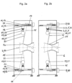
- the Figures 2a, b show two operating phases of the weaving process in the circular loom with changing positioning of the guide carriages 11 with the warp threads 15 during the rotation of the two shuttles 19 by 180° each.
- the two rotating shuttles 19 are in the 6 o'clock and 12 o'clock positions of the circular loom, with some guide carriages 13, including the guide carriage 13 of the guide device 11 arranged in the 12 o'clock position, with the warp thread 15 in the image plane to the right of the orbit 3 and further guide carriages 13, including the guide carriage 13 of the guide device 11 arranged in the 6 o'clock position, with the warp thread 15 in the image plane to the left of the orbit 3, so that the space for the passage of the shuttles 19 at the 6 o'clock and 12 o'clock positions is released by the warp threads 15 spread out from the track plane 8 to form a sheathing.
- any number of guide carriages 13, for example every second, third or all guide carriages 13 of the guide devices 11 can be located to the right or left of the orbit 3 in the image plane during one revolution of the gate 19.
- Fig. 2b shows the operating phase of the circular loom in which the shuttle 19 previously located at the 6 o'clock position passes through the 12 o'clock position and vice versa, whereby some guide carriages 13, including the guide carriage 13 of the guide devices 11 arranged at the 6 o'clock and 12 o'clock positions, with the warp thread 15 are located in the image plane to the right of the orbit 3, while the shuttles 19 pass through the 6 o'clock and 12 o'clock positions.
- any number of guide carriages 13, for example every second, third or all guide carriages 13 of the 12 guide devices 11, can be located in the image plane to the right or left of the orbit 3.
- the contactors 19 can rotate on the guide rails 7 at symmetrical or asymmetrical distances from one another.
- the warp threads 15 are alternately spread in opposite directions in the above-described or another alternating mode of the guide carriages 13, which results in an undulation of the warp threads 15 with the weft threads 22 of the shuttle 19 rotating on the orbit 3 in a certain mode, to produce a hollow profile-like fabric 25 with the desired weave pattern, as shown in Fig. 2a, b shown.
- the irregularly profiled weaving core 1a can be moved axially along the weaving axis 2 during the weaving process, with the fabric 25 being deposited on the weaving core 1a in a fixed/stationary manner.
- the axial movement of the weaving core 1a can be quasi-stationary, discontinuous or continuous, for example, depending on the desired weaving result.
- a forward and backward movement of the weaving core 1a to produce several fabric layers 25 is also possible.
- the weaving core 1a can additionally be set in rotation about its weaving core axis 17 or be made to incline to the weaving axis 2 in order to produce a changed angular position of the warp threads 15 and the weft threads 22 of e.g. +/- 60° to the weaving core axis 17 on the weaving core 1a.
- the uniform weaving structure shown as a result of a uniform weaving mode can be changed by means of the individual drive and control of both the shuttle carriage 20 and the guide carriage 13 and the weaving core 1a, even during the weaving process.
- the shuttle carriages 20 can rotate very precisely and evenly by means of the guide rails 7 and at the same time apply a high thread tension to the weft thread 22 carried along.
- the narrow gaps 18 in the orbit 3 for the passage of the warp threads 15 can be formed by means of the large number of widely spaced, rubberized guide rollers can be easily rolled over with as little influence as possible on the gate carriage 20, so that the even rotation of the gate 19 is not impaired.
- the rapid, alternating spreading of the warp threads 15 by means of the guide carriages 13 which can be operated over short distances further makes it possible to increase the running speed of the shuttles 19 rotating on the guide rails 7.
- weaving the weaving core 1a After weaving the weaving core 1a, it can be removed sideways from the circular weaving machine and the circular weaving machine can be equipped with another weaving core to be weaved.
- the circular weaving machine is particularly suitable for weaving large, irregularly contoured weaving cores with contour-conforming technical fabrics, such as for the production of woven hollow-profiled fiber preforms for wheel rims.
- FIGS. 3 , 4 and 5 show a first embodiment of the circular weaving machine according to the invention, here for weaving a cylindrical weaving core 1b.
- the warp spool devices 9 are arranged fixed to the housing essentially in extension of the radial extent of the circular orbit 3 on an outer wall of the machine housing 6 of the circular weaving machine.
- the after Fig.3 and 4 The 12 warp spool devices 9 provided are arranged essentially centrally in the extension of the track plane 8 of the orbit 3.
- the after Fig.5 The 24 warp spool devices 9 provided are arranged in pairs, next to one another in the axial direction, wherein the mirror line of a pair of warp spool devices 9 is arranged essentially centrally in the extension of the track plane 8.
- the 12 warp bobbin devices 9 after Fig.3 and 4 are each assigned to a movable, movable guide device 11, so that one warp thread 15 is guided per guide device 11.
- the 24 warp bobbin devices 9 according to Fig.5 are assigned in pairs to a movable, movable guide device 11, so that two warp threads 15 are guided per guide device 11.
- the guide carriage 13 of the guide device 11 according to Fig. 4 and 5 has a thread guide element 14 with a radially directed thread channel 14, to which the thread outlet 16 is connected.
- the warp spool device 9 according to Fig.4 The warp threads 15 provided run individually through a radially directed thread channel 14 of a guide carriage 13 and the warp spool device 9 to Fig.5
- the warp threads 15 provided run in pairs through a radially directed thread channel 15 of a guide carriage 13.
- the radially directed thread channel 14 with the warp thread 15 or the two warp threads 15 is alternately in a position to the right and left of the orbit 3 or the track plane 8.
- momentary intermediate positions of the thread channel 14 arise, such as a central position, in which the radially directed thread channel 14 is essentially in a straight line extension to the housing-fixed arrangement of the warp thread spool 10 of the warp spool device 9 and thus temporarily enables a deflection-free travel path of the warp thread 15 through the thread channel 14.
- the necessary thread deflections and absolute thread length of the warp threads 15 are reduced and, in particular, the different, relative thread lengths resulting from the sideways movement of the guide carriages 14 are minimized, which further improves the maintenance of the thread tension of the warp threads 15.
- the cylindrical weaving core 1b When weaving the cylindrical weaving core 1b, it can be fixed stationary during the weaving process, for example, with the fabric 25 being continuously pulled off in the axial direction along the weaving axis 2 of the circular weaving machine or along the core path axis 17 of the weaving core 1b.
- the weaving core 1b is preferably aligned in a congruent axial position with the weaving axis 2.
- a weaving ring 26 fixed to the housing is arranged concentrically spaced around the weaving core 1b, which additionally homogenizes the supply of the warp threads 15 and weft threads 22 to the weaving point by dampening their thread vibrations and compensating their thread tension fluctuations, which has an advantageous effect in particular in circular weaving machines with a larger diameter of the orbit 3 and thus with a larger distance between the weft thread spool 21 and the thread outlets 16 of the thread guide elements 14 of the guide devices 11 from the weaving core 1b.
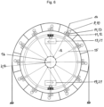
- FIGS. 6 , 7a , b show a second embodiment of the circular weaving machine according to the invention for weaving a cylindrical weaving core 1b.
- the 12 warp spool devices 9 are each arranged on a guide carriage 13 of the 12 guide devices 11 and are carried along with it in the piggyback principle.
- the warp spool device 9 is arranged on the guide carriage 13 in such a way that the warp thread spool 10 is essentially in a straight line extension to the radially directed thread channel 14 and thus always enables a deflection-free travel path of the warp thread 15 through the thread channel 14.
- the Figures 7a, b show two operating phases of the weaving process in the circular loom with changing positioning of the guide carriages 13 with the warp spool devices 9 during the rotation of the two shuttles 19 by 180° each.
- the two rotating shuttles 19 are in the 6 o'clock and 12 o'clock positions of the circular loom, whereby, to form a warp thread ply, the guide carriage 13 of the guide device 11 arranged in the 12 o'clock position with the warp spool device 9 and the warp thread 15 is located in the image plane to the right of the orbit 3 and, among other things, the guide carriage 13 of the guide device 11 arranged in the 6 o'clock position with the warp spool device 9 and the warp thread 15 is located in the image plane to the left of the orbit 3, while the shuttles 19 pass through the 6 o'clock and 12 o'clock positions.
- Fig. 7b shows the operating phase of the circular weaving machine in which the shuttle 19, previously located at the 6 o'clock position, passes through the 12 o'clock position and vice versa, whereby now, among other things, the guide carriages 13 of the guide devices 11 arranged at the 6 o'clock and 12 o'clock positions with the warp bobbin device 9 and the warp thread 15 are located in the image plane to the right of the orbit 3, while the shuttles 19 pass through the 6 o'clock and 12 o'clock positions.
- FIGS. 8a, b, c show a third embodiment of the circular loom according to the invention for weaving a cylindrical weaving core 1b.
- the circular weaving machine according to this embodiment has two circular orbits 3.1, 3.2 arranged parallel to one another for the rail-guided circulation of two shuttles 19 each.
- a total of 12 guide devices 11 are assigned to the two orbits 3.1, 3.2, each of which carries a warp spool device 9 arranged on the respective guide carriage 13.
- each guide device 11 extends in the axial direction over the two track bodies 4.1, 4.2 of the orbits 3.1, 3.2, so that the guide carriage 13 and the warp thread 15 carried along by each guide device 11 can cross both track bodies 4.1, 4.2 and thus both track planes 8.1, 8.2 along the base body 12 and, in accordance with the exemplary operating phase according to
- Fig. 8a in the image plane to the left of the first orbit 3.1, corresponding to the operational phase after Fig. 8b midway between the first and second orbits 3.1, 3.2 and according to the operational phase after Fig. 8c to the right of the second orbit 3.2.
- FIGS. 9a, b, c show a fourth embodiment of the circular weaving machine according to the invention for weaving a cylindrical weaving core 1b.
- the 12 guide devices 11 each have two guide carriages 13.1, 13.2, each with a thread guide element 14.1, 14.2 as a radially directed thread channel 14.1, 14.2.
- a warp spool device 9 is arranged on each of the 24 guide carriages 13.1, 13.2, which guide the guide carriages 13.1, 13.2 with them.
- the two guide carriages 13.1, 13.2 of each guide device 11 can be positioned as desired along the base body 12 extending over both track bodies 4.1, 4.2 of the orbits 3.1, 3.2.
- the first guide carriage 13.1 and its warp thread 15 are located centrally between the first and second orbits 3.1, 3.2 and the second guide carriage 13.2 and its warp thread 15 are located to the right of the second orbit 3.2.
- the first guide carriage 13.1 and its carried warp thread 15 are again in the position to the left of the first orbit 3.1, while the second guide carriage 13.2 and its carried warp thread 13.2 remain in the position to the right of the second orbit 3.2.
- FIGS 10a, b show a circular weaving machine not according to the invention, here for weaving a contoured, two-part weaving core 1a, analogous to the circular weaving machine according to the Figures 1 , 2a , b.
- 12 movable, pivotable guide devices 11 are alternatively provided, which are arranged concentrically around the central weaving axis 2 of the circular weaving machine, outside the circular orbit 3 or the track plane 8 and essentially in extension of the radial extent of the orbit 3 or the track plane 8 on an outer wall of the machine housing 6 of the circular weaving machine.
- the pivotable guide devices 11 each have a pivot joint 27 fixed to the housing as a base body 27 and a positioning part 28 rotatably mounted on the pivot joint 27, which in the exemplary embodiment is designed as a pivot arm 28.
- the swivel arm 28 has at its free end a thread guide element 29 for guiding and directing the warp thread 15 in the form of a thread guide eyelet 29 through which the warp thread 15 is guided.
- the warp thread 15 can be alternately guided to both sides of the segmented Orbit 3, whereby only a single thread deflection is required with little friction in the thread guide eyelet 29.
- the feeding of the warp threads 15 from the warp thread spools 10 via the thread guide eyelet 29 to the weaving point on the weaving core 1a thus also takes place in a largely straight line, whereby the thread tension of the warp threads 15 can be maintained at a high level.
- each guide device 11 can be carried out analogously to the embodiment according to Fig.1 , 2a, b individually, e.g. via individual, switchable direct drives acting in two directions (not shown).
- Fig. 10a, b the two orbiting contactors 19 are shown schematically in the 6 o'clock and 12 o'clock positions along the orbit 3.
- FIG. 10a, b only two warp spool devices 9 and the associated pivotable guide devices 11 are shown, namely the warp spool devices 9 and guide devices 11 arranged in the 6 o'clock and 12 o'clock positions of the circular loom.
- FIGS. 10a, b show two operating phases of the weaving process in the circular loom with alternating positioning of the swivel arms 28 with the thread guide eyelets 29 guiding the warp threads 15 during the rotation of the two shuttles 19 by 180° each.
- the two rotating shuttles 19 are in the 6 o'clock and 12 o'clock positions of the circular loom, wherein, among other things, the swivel arm 28 with the warp thread 15 in the thread guide eyelet 29 of the guide device 11 arranged in the 12 o'clock position is pivoted out to the right of the orbit 3 in the image plane and, among other things, the swivel arm 28 with the warp thread 15 of the guide device 11 arranged in the 6 o'clock position is pivoted out to the left of the orbit 3 in the image plane, so that the space for the passage of the shuttles 19 at the 6 o'clock and 12 o'clock positions is released by the warp threads 15 spread out from the track plane 8, forming a sheathing.
- Fig. 10b shows the operating phase of the circular weaving machine in which the shuttle 19, previously located at the 6 o'clock position, passes through the 12 o'clock position and vice versa, whereby, among other things, the pivot arms 28 with the warp threads 15 of the guide devices arranged at the 6 o'clock and 12 o'clock positions are pivoted out in the image plane to the right of the orbit 3, while the shuttles 19 pass through the 6 o'clock and 12 o'clock positions.
Landscapes
- Engineering & Computer Science (AREA)
- Textile Engineering (AREA)
- Looms (AREA)
Claims (10)
- Métier circulaire destiné à tisser une âme textile, comprenant au moins une navette (19) qui présente une bobine (21) de fil de trame et qui est déplaçable le long d'une piste de circulation (3) circonférentielle autour de l'âme textile (1), comprenant au moins un dispositif (9) pour bobines de chaîne disposé stationnaire, dispositif qui présente une bobine (10) de fil de chaîne qui est disposées pour l'essentiel dans le prolongement de l'extension radiale de la piste de circulation (3) circonférentielle, sachant qu'est prévu au moins un dispositif de guidage (11), configuré pour guider au moins un fil de chaîne (15) mis à disposition par une bobine (10) de fil d'un dispositif (9) pour bobines de fil de chaîne, dispositif qui est disposé ou configuré mobile en dehors d'un plan (8) de piste englobé par la périphérie extérieure de la piste de circulation (3) circonférentielle, et qui présente au moins une pièce de positionnement (13) - avec au moins un élément de guidage (14) de fil - disposée ou configurée pour se déplacer parallèlement à l'axe de tissage (2) du métier à tisser circulaire, sachant que la bobine (10) de fil de chaîne du dispositif (9) pour bobines de chaîne est disposée pour l'essentiel dans le prolongement rectiligne, donc sans déviation, du chemin de déplacement du fil de chaîne (15) à travers l'élément de guidage (14) de fil et sachant que seulement le fil de chaîne (15) guidé franchit, en traversant le plan (8) de piste, un évidement (18) de la piste de circulation (3) circonférentielle.
- Métier circulaire destiné à tisser une âme textile, comprenant au moins une navette (19) qui présente une bobine (21) de fil de trame et qui est déplaçable le long d'une piste de circulation (3) circonférentielle autour de l'âme textile (1), sachant qu'est prévu au moins un dispositif de guidage (11), configuré pour guider au moins un fil de chaîne (15) mis à disposition par une bobine (10) de fil d'un dispositif (9) pour bobines de fil de chaîne, dispositif qui est disposé ou configuré mobile en dehors d'un plan (8) de piste englobé par la périphérie extérieure de la piste de circulation (3) circonférentielle, et qui présente au moins une pièce de positionnement (13) - avec au moins un élément de guidage (14) de fil - disposée ou configurée pour se déplacer parallèlement à l'axe de tissage (2) du métier à tisser circulaire, sachant que contre le dispositif de guidage (11) mobile ou la pièce de positionnement (13) est disposé au moins un dispositif (9) pour bobines de fil de chaîne, sachant que la bobine (10) de fil de chaîne du dispositif (9) pour bobines de chaîne est disposée pour l'essentiel dans le prolongement rectiligne, donc sans déviation, du chemin de déplacement du fil de chaîne (15) à travers l'élément (14) de guidage du fil et sachant que seulement le fil de chaîne (15) guidé franchit, en traversant le plan de piste (8), un évidement (18) de la piste de circulation (3) circonférentielle.
- Métier à tisser circulaire selon la revendication 1 ou 2, caractérisé en ce que les bobines de fil de chaîne (10) de plusieurs dispositifs (9) pour bobines de fil de chaîne sont disposées selon un agencement radial, en étoile, autour de la périphérie extérieure de la piste de circulation (3) circonférentielle.
- Métier à tisser circulaire selon l'une des revendications 1 à 3, caractérisé en ce que plusieurs dispositifs de guidage (11) sont disposés autour de la périphérie de la piste de circulation (3) circonférentielle.
- Métier à tisser circulaire selon l'une des revendications 1 à 4, caractérisé en ce que l'élément de guidage (14) du fil équipant le dispositif de guidage (11) est configuré en conduit de guidage (14) du fil ou en gorge de guidage du fil.
- Dispositif selon l'une des revendications 1 à 5, caractérisé en ce que la pièce de positionnement (13) est configurée en chariot de guidage (13).
- Métier à tisser circulaire selon la revendication 6, caractérisé en ce que le chariot de guidage (13) présente un élément de guidage (14) du fil avec un conduit de guidage (14) du fil orienté radialement.
- Métier à tisser circulaire selon l'une des revendications 1 à 7, caractérisé en ce que la piste de circulation (3) circonférentielle présente au moins un rail de guidage (7) ou est formée par au moins un rail de guidage (7) dans ou contre lequel est guidée une navette (19).
- Métier à tisser circulaire selon l'une des revendications 1 à 8, caractérisé en ce que le guidage et/ou l'entraînement de la navette (19) est configuré magnétique et/ou électromagnétique.
- Métier à tisser circulaire selon l'une des revendications 1 à 9, caractérisé en ce qu'une deuxième piste de circulation (3.2) circonférentielle est prévue, le long de laquelle est déplaçable respectivement au moins une navette (19), sachant que le fil de chaîne (15) guidé franchit, en traversant les plans de piste (8.1, 8.2) de la première et/ou de la deuxième piste de circulation (3.1, 3.2), l'évidement (18) de la première et/ou de la deuxième piste de circulation (3.1, 3.2) circonférentielle.
Priority Applications (1)
| Application Number | Priority Date | Filing Date | Title |
|---|---|---|---|
| EP24196175.4A EP4455378B1 (fr) | 2019-07-24 | 2020-07-23 | Métier à tisser circulaire orbital |
Applications Claiming Priority (2)
| Application Number | Priority Date | Filing Date | Title |
|---|---|---|---|
| DE102019120037.7A DE102019120037B3 (de) | 2019-07-24 | 2019-07-24 | Rundwebmaschine mit Umlaufbahn |
| DE102019120035.0A DE102019120035B3 (de) | 2019-07-24 | 2019-07-24 | Rundwebmaschine mit Umlaufbahn |
Related Child Applications (2)
| Application Number | Title | Priority Date | Filing Date |
|---|---|---|---|
| EP24196175.4A Division EP4455378B1 (fr) | 2019-07-24 | 2020-07-23 | Métier à tisser circulaire orbital |
| EP24196175.4A Previously-Filed-Application EP4455378B1 (fr) | 2019-07-24 | 2020-07-23 | Métier à tisser circulaire orbital |
Publications (2)
| Publication Number | Publication Date |
|---|---|
| EP3770310A1 EP3770310A1 (fr) | 2021-01-27 |
| EP3770310B1 true EP3770310B1 (fr) | 2024-09-04 |
Family
ID=71783941
Family Applications (3)
| Application Number | Title | Priority Date | Filing Date |
|---|---|---|---|
| EP24196175.4A Active EP4455378B1 (fr) | 2019-07-24 | 2020-07-23 | Métier à tisser circulaire orbital |
| EP20187489.8A Active EP3770311B1 (fr) | 2019-07-24 | 2020-07-23 | Métier à tisser circulaire à trajectoire périphérique |
| EP20187472.4A Active EP3770310B1 (fr) | 2019-07-24 | 2020-07-23 | Métier à tisser circulaire à trajectoire périphérique |
Family Applications Before (2)
| Application Number | Title | Priority Date | Filing Date |
|---|---|---|---|
| EP24196175.4A Active EP4455378B1 (fr) | 2019-07-24 | 2020-07-23 | Métier à tisser circulaire orbital |
| EP20187489.8A Active EP3770311B1 (fr) | 2019-07-24 | 2020-07-23 | Métier à tisser circulaire à trajectoire périphérique |
Country Status (4)
| Country | Link |
|---|---|
| US (2) | US11352721B2 (fr) |
| EP (3) | EP4455378B1 (fr) |
| CN (2) | CN112281283A (fr) |
| PT (1) | PT3770310T (fr) |
Families Citing this family (3)
| Publication number | Priority date | Publication date | Assignee | Title |
|---|---|---|---|---|
| US11352721B2 (en) * | 2019-07-24 | 2022-06-07 | Innotec Lightweight Engineering & Polymer Technology Gmbh | Circular loom with orbit path |
| CN113046894B (zh) * | 2021-04-21 | 2022-10-04 | 西安英利科电气科技有限公司 | 一种三维管状预制体织机结构 |
| CN114164542A (zh) * | 2021-12-15 | 2022-03-11 | 国网江苏省电力有限公司南通供电分公司 | 一种织管机磁悬浮放纬机构 |
Family Cites Families (25)
| Publication number | Priority date | Publication date | Assignee | Title |
|---|---|---|---|---|
| US920728A (en) | 1908-07-03 | 1909-05-04 | Chernack Circular Loom Company | Circular loom. |
| FR2030124A1 (en) | 1969-01-06 | 1970-10-30 | Hitco | Thick walled, highly compact, complex, shaped - textile bodies for flexible conveyor belts, tyres |
| DE1963208C3 (de) * | 1969-12-17 | 1974-07-04 | Adolf 7451 Hechingensickingen Linka | Wellenwebmaschine |
| JPS5063271A (fr) * | 1973-10-11 | 1975-05-29 | ||
| GB1399711A (en) * | 1973-10-12 | 1975-07-02 | Torii Winding Machine Co | Shuttle arrangement in a circular loom for weaving tape yarn |
| FR2339009A1 (fr) | 1976-01-23 | 1977-08-19 | Models Designs Dev Europ | Perfectionnement aux machines a tisser circulaires |
| JPS5841271B2 (ja) * | 1978-11-29 | 1983-09-10 | 宗一 鳥居 | 糸の張力調整送り装置 |
| JPS5576138A (en) * | 1978-11-29 | 1980-06-09 | Souichi Torii | Shatle propelling system in circular loom |
| US4234021A (en) * | 1978-12-20 | 1980-11-18 | Greenbat Limited | Circular looms |
| IT1113866B (it) * | 1979-04-11 | 1986-01-27 | Moplefan Spa | Telaio circolare ad alta velocita' per la produzione di tessuti tubolari a partire da fili,striscie,piattine e simili di sostanze sintetiche e naturali |
| IT1134709B (it) * | 1980-12-12 | 1986-08-13 | Moplefan Spa | Telaio circolare silenzioso ad alta velocita' per la produzione di tessuti tubolari costituiti da striscie fili e simili in materiale sintetico o naturale |
| AT371846B (de) * | 1981-11-25 | 1983-08-10 | Chemiefaser Lenzing Ag | Rundwebmaschine |
| AT375410B (de) * | 1982-11-11 | 1984-08-10 | Chemiefaser Lenzing Ag | Rundwebmaschine |
| CH664384A5 (de) * | 1984-06-08 | 1988-02-29 | Huemer Franz Xaver | Antriebseinrichtung an einer rundwebmaschine. |
| CH663227A5 (de) * | 1984-06-08 | 1987-11-30 | Huemer Franz Xaver | Rundwebmaschine. |
| US4977933A (en) * | 1985-05-28 | 1990-12-18 | Joss Company | Circular loom for weaving ribbon-shaped materials |
| AT383834B (de) * | 1985-10-10 | 1987-08-25 | Chemiefaser Lenzing Ag | Verfahren zum herstellen eines schlauchgewebes sowie rundwebmaschine zur durchfuehrung des verfahrens |
| AT385784B (de) * | 1986-07-14 | 1988-05-10 | Chemiefaser Lenzing Ag | Rundwebmaschine |
| JPH01168938A (ja) | 1987-12-24 | 1989-07-04 | Toyota Autom Loom Works Ltd | 三次元環状織物の製造方法 |
| JPH0684574B2 (ja) * | 1989-05-02 | 1994-10-26 | 株式会社鳥居鉄工所 | 円形織機の経糸開口装置 |
| US5293906A (en) * | 1989-12-18 | 1994-03-15 | Quadrax Corporation | Circular loom for and method of weaving ribbon-shaped weft |
| DE4112770A1 (de) * | 1991-04-19 | 1992-10-22 | Rmb | Rundwebmaschine |
| CN1103390C (zh) | 2001-02-23 | 2003-03-19 | 北京玻璃钢研究设计院 | 一种织机 |
| DE112017002308A5 (de) * | 2016-05-04 | 2019-03-14 | Innotec Lightweight Engineering & Polymer Technology Gmbh | Rundwebmaschine und Verfahren zur Herstellung eines hohlprofilartigen Gewebes |
| US11352721B2 (en) * | 2019-07-24 | 2022-06-07 | Innotec Lightweight Engineering & Polymer Technology Gmbh | Circular loom with orbit path |
-
2020
- 2020-07-22 US US16/935,381 patent/US11352721B2/en active Active
- 2020-07-22 US US16/935,388 patent/US11155941B2/en active Active
- 2020-07-23 CN CN202010728761.4A patent/CN112281283A/zh active Pending
- 2020-07-23 EP EP24196175.4A patent/EP4455378B1/fr active Active
- 2020-07-23 EP EP20187489.8A patent/EP3770311B1/fr active Active
- 2020-07-23 PT PT201874724T patent/PT3770310T/pt unknown
- 2020-07-23 CN CN202010728882.9A patent/CN112281284A/zh active Pending
- 2020-07-23 EP EP20187472.4A patent/EP3770310B1/fr active Active
Also Published As
| Publication number | Publication date |
|---|---|
| US11352721B2 (en) | 2022-06-07 |
| PT3770310T (pt) | 2024-11-06 |
| EP4455378B1 (fr) | 2026-04-15 |
| US20210032784A1 (en) | 2021-02-04 |
| EP4455378A2 (fr) | 2024-10-30 |
| CN112281283A (zh) | 2021-01-29 |
| EP3770310A1 (fr) | 2021-01-27 |
| US11155941B2 (en) | 2021-10-26 |
| EP3770311A1 (fr) | 2021-01-27 |
| EP4455378A3 (fr) | 2025-01-22 |
| US20210025087A1 (en) | 2021-01-28 |
| CN112281284A (zh) | 2021-01-29 |
| EP3770311B1 (fr) | 2022-06-15 |
Similar Documents
| Publication | Publication Date | Title |
|---|---|---|
| EP3452648B1 (fr) | Métier à tisser circulaire et procédé de fabrication d'un tissu de type à profilé creux | |
| EP3770310B1 (fr) | Métier à tisser circulaire à trajectoire périphérique | |
| EP2003232B1 (fr) | Procédé et dispositif destinés à la création d'une couche de fibre unidirectionnelle, procédé destiné à la fabrication d'une mêche et dispositif multiaxiale, et procédé de la fabrication d'un tissu fibreux et un métier à tisser | |
| EP1369370B1 (fr) | Procédé et dispositif pour déposer un câble de filaments | |
| EP3662100B1 (fr) | Ros et métier à tisser circulaire | |
| EP2284304B1 (fr) | Ourdissoir à chaîne de motif et procédé de production d'une chaîne de motif | |
| EP2155955B1 (fr) | Machine à toronner à double torsion | |
| DE102007041696B4 (de) | Changiereinrichtung | |
| DE1760528B1 (de) | Verfahren und Vorrichtung zur Herstellung eines mehrfaedigen,mittels Falschdrall in sich verfestigten Zwirns | |
| EP3822401B1 (fr) | Dispositif destiné à la fabrication d'un tissu et procédé correspondant | |
| DE102013000824A1 (de) | Aufspulmaschine | |
| DE102019120035B3 (de) | Rundwebmaschine mit Umlaufbahn | |
| DE102019120037B3 (de) | Rundwebmaschine mit Umlaufbahn | |
| WO2008098873A1 (fr) | Dispositif de bobinage | |
| DE102013108096A1 (de) | Spinnmaschine und Falschdralleinrichtung | |
| DE10231302B4 (de) | Durchtrittsschleuse für einen beidseitig eingespannt bleibenden und laufenden Faden und Rotorflechtmaschine zum Umflechten von Langobjekten | |
| DE1635481B2 (de) | Maschine zur herstellung eines endlosen fadengeleges | |
| DE102018212847B3 (de) | Vorrichtung zum Einstellen der Kettspannung von Kettfäden | |
| EP3837390B1 (fr) | Appareil pour la production d'une gaine tressée | |
| EP0216121B1 (fr) | Méthode et dispositif pour former des bobines croisées | |
| EP1975288A2 (fr) | Machine à filer | |
| DE3835873C2 (fr) | ||
| DE3734481C2 (fr) | ||
| DE948906C (de) | Vorrichtung zum Herstellen von Chenille | |
| EP1052317A1 (fr) | Dispositif et procédé pour fournir un fil de tour à un métier à tisser |
Legal Events
| Date | Code | Title | Description |
|---|---|---|---|
| PUAI | Public reference made under article 153(3) epc to a published international application that has entered the european phase |
Free format text: ORIGINAL CODE: 0009012 |
|
| STAA | Information on the status of an ep patent application or granted ep patent |
Free format text: STATUS: THE APPLICATION HAS BEEN PUBLISHED |
|
| AK | Designated contracting states |
Kind code of ref document: A1 Designated state(s): AL AT BE BG CH CY CZ DE DK EE ES FI FR GB GR HR HU IE IS IT LI LT LU LV MC MK MT NL NO PL PT RO RS SE SI SK SM TR |
|
| AX | Request for extension of the european patent |
Extension state: BA ME |
|
| RIN1 | Information on inventor provided before grant (corrected) |
Inventor name: HUFENBACH, WERNER |
|
| STAA | Information on the status of an ep patent application or granted ep patent |
Free format text: STATUS: REQUEST FOR EXAMINATION WAS MADE |
|
| 17P | Request for examination filed |
Effective date: 20210723 |
|
| RBV | Designated contracting states (corrected) |
Designated state(s): AL AT BE BG CH CY CZ DE DK EE ES FI FR GB GR HR HU IE IS IT LI LT LU LV MC MK MT NL NO PL PT RO RS SE SI SK SM TR |
|
| STAA | Information on the status of an ep patent application or granted ep patent |
Free format text: STATUS: EXAMINATION IS IN PROGRESS |
|
| 17Q | First examination report despatched |
Effective date: 20220207 |
|
| P01 | Opt-out of the competence of the unified patent court (upc) registered |
Effective date: 20230507 |
|
| GRAP | Despatch of communication of intention to grant a patent |
Free format text: ORIGINAL CODE: EPIDOSNIGR1 |
|
| STAA | Information on the status of an ep patent application or granted ep patent |
Free format text: STATUS: GRANT OF PATENT IS INTENDED |
|
| INTG | Intention to grant announced |
Effective date: 20240221 |
|
| GRAS | Grant fee paid |
Free format text: ORIGINAL CODE: EPIDOSNIGR3 |
|
| GRAA | (expected) grant |
Free format text: ORIGINAL CODE: 0009210 |
|
| STAA | Information on the status of an ep patent application or granted ep patent |
Free format text: STATUS: THE PATENT HAS BEEN GRANTED |
|
| AK | Designated contracting states |
Kind code of ref document: B1 Designated state(s): AL AT BE BG CH CY CZ DE DK EE ES FI FR GB GR HR HU IE IS IT LI LT LU LV MC MK MT NL NO PL PT RO RS SE SI SK SM TR |
|
| REG | Reference to a national code |
Ref country code: GB Ref legal event code: FG4D Free format text: NOT ENGLISH |
|
| REG | Reference to a national code |
Ref country code: CH Ref legal event code: EP |
|
| REG | Reference to a national code |
Ref country code: DE Ref legal event code: R096 Ref document number: 502020009082 Country of ref document: DE |
|
| REG | Reference to a national code |
Ref country code: IE Ref legal event code: FG4D Free format text: LANGUAGE OF EP DOCUMENT: GERMAN |
|
| REG | Reference to a national code |
Ref country code: PT Ref legal event code: SC4A Ref document number: 3770310 Country of ref document: PT Date of ref document: 20241106 Kind code of ref document: T Free format text: AVAILABILITY OF NATIONAL TRANSLATION Effective date: 20241030 |
|
| REG | Reference to a national code |
Ref country code: LT Ref legal event code: MG9D |
|
| REG | Reference to a national code |
Ref country code: NL Ref legal event code: MP Effective date: 20240904 |
|
| PG25 | Lapsed in a contracting state [announced via postgrant information from national office to epo] |
Ref country code: NO Free format text: LAPSE BECAUSE OF FAILURE TO SUBMIT A TRANSLATION OF THE DESCRIPTION OR TO PAY THE FEE WITHIN THE PRESCRIBED TIME-LIMIT Effective date: 20241204 |
|
| PG25 | Lapsed in a contracting state [announced via postgrant information from national office to epo] |
Ref country code: GR Free format text: LAPSE BECAUSE OF FAILURE TO SUBMIT A TRANSLATION OF THE DESCRIPTION OR TO PAY THE FEE WITHIN THE PRESCRIBED TIME-LIMIT Effective date: 20241205 Ref country code: FI Free format text: LAPSE BECAUSE OF FAILURE TO SUBMIT A TRANSLATION OF THE DESCRIPTION OR TO PAY THE FEE WITHIN THE PRESCRIBED TIME-LIMIT Effective date: 20240904 Ref country code: PL Free format text: LAPSE BECAUSE OF FAILURE TO SUBMIT A TRANSLATION OF THE DESCRIPTION OR TO PAY THE FEE WITHIN THE PRESCRIBED TIME-LIMIT Effective date: 20240904 |
|
| PG25 | Lapsed in a contracting state [announced via postgrant information from national office to epo] |
Ref country code: BG Free format text: LAPSE BECAUSE OF FAILURE TO SUBMIT A TRANSLATION OF THE DESCRIPTION OR TO PAY THE FEE WITHIN THE PRESCRIBED TIME-LIMIT Effective date: 20240904 |
|
| PG25 | Lapsed in a contracting state [announced via postgrant information from national office to epo] |
Ref country code: LV Free format text: LAPSE BECAUSE OF FAILURE TO SUBMIT A TRANSLATION OF THE DESCRIPTION OR TO PAY THE FEE WITHIN THE PRESCRIBED TIME-LIMIT Effective date: 20240904 |
|
| PG25 | Lapsed in a contracting state [announced via postgrant information from national office to epo] |
Ref country code: HR Free format text: LAPSE BECAUSE OF FAILURE TO SUBMIT A TRANSLATION OF THE DESCRIPTION OR TO PAY THE FEE WITHIN THE PRESCRIBED TIME-LIMIT Effective date: 20240904 |
|
| PG25 | Lapsed in a contracting state [announced via postgrant information from national office to epo] |
Ref country code: RS Free format text: LAPSE BECAUSE OF FAILURE TO SUBMIT A TRANSLATION OF THE DESCRIPTION OR TO PAY THE FEE WITHIN THE PRESCRIBED TIME-LIMIT Effective date: 20241204 Ref country code: ES Free format text: LAPSE BECAUSE OF FAILURE TO SUBMIT A TRANSLATION OF THE DESCRIPTION OR TO PAY THE FEE WITHIN THE PRESCRIBED TIME-LIMIT Effective date: 20240904 |
|
| PG25 | Lapsed in a contracting state [announced via postgrant information from national office to epo] |
Ref country code: RS Free format text: LAPSE BECAUSE OF FAILURE TO SUBMIT A TRANSLATION OF THE DESCRIPTION OR TO PAY THE FEE WITHIN THE PRESCRIBED TIME-LIMIT Effective date: 20241204 Ref country code: PL Free format text: LAPSE BECAUSE OF FAILURE TO SUBMIT A TRANSLATION OF THE DESCRIPTION OR TO PAY THE FEE WITHIN THE PRESCRIBED TIME-LIMIT Effective date: 20240904 Ref country code: NO Free format text: LAPSE BECAUSE OF FAILURE TO SUBMIT A TRANSLATION OF THE DESCRIPTION OR TO PAY THE FEE WITHIN THE PRESCRIBED TIME-LIMIT Effective date: 20241204 Ref country code: LV Free format text: LAPSE BECAUSE OF FAILURE TO SUBMIT A TRANSLATION OF THE DESCRIPTION OR TO PAY THE FEE WITHIN THE PRESCRIBED TIME-LIMIT Effective date: 20240904 Ref country code: HR Free format text: LAPSE BECAUSE OF FAILURE TO SUBMIT A TRANSLATION OF THE DESCRIPTION OR TO PAY THE FEE WITHIN THE PRESCRIBED TIME-LIMIT Effective date: 20240904 Ref country code: GR Free format text: LAPSE BECAUSE OF FAILURE TO SUBMIT A TRANSLATION OF THE DESCRIPTION OR TO PAY THE FEE WITHIN THE PRESCRIBED TIME-LIMIT Effective date: 20241205 Ref country code: FI Free format text: LAPSE BECAUSE OF FAILURE TO SUBMIT A TRANSLATION OF THE DESCRIPTION OR TO PAY THE FEE WITHIN THE PRESCRIBED TIME-LIMIT Effective date: 20240904 Ref country code: ES Free format text: LAPSE BECAUSE OF FAILURE TO SUBMIT A TRANSLATION OF THE DESCRIPTION OR TO PAY THE FEE WITHIN THE PRESCRIBED TIME-LIMIT Effective date: 20240904 Ref country code: BG Free format text: LAPSE BECAUSE OF FAILURE TO SUBMIT A TRANSLATION OF THE DESCRIPTION OR TO PAY THE FEE WITHIN THE PRESCRIBED TIME-LIMIT Effective date: 20240904 |
|
| PG25 | Lapsed in a contracting state [announced via postgrant information from national office to epo] |
Ref country code: NL Free format text: LAPSE BECAUSE OF FAILURE TO SUBMIT A TRANSLATION OF THE DESCRIPTION OR TO PAY THE FEE WITHIN THE PRESCRIBED TIME-LIMIT Effective date: 20240904 |
|
| PG25 | Lapsed in a contracting state [announced via postgrant information from national office to epo] |
Ref country code: IS Free format text: LAPSE BECAUSE OF FAILURE TO SUBMIT A TRANSLATION OF THE DESCRIPTION OR TO PAY THE FEE WITHIN THE PRESCRIBED TIME-LIMIT Effective date: 20250104 |
|
| PG25 | Lapsed in a contracting state [announced via postgrant information from national office to epo] |
Ref country code: RO Free format text: LAPSE BECAUSE OF FAILURE TO SUBMIT A TRANSLATION OF THE DESCRIPTION OR TO PAY THE FEE WITHIN THE PRESCRIBED TIME-LIMIT Effective date: 20240904 Ref country code: SM Free format text: LAPSE BECAUSE OF FAILURE TO SUBMIT A TRANSLATION OF THE DESCRIPTION OR TO PAY THE FEE WITHIN THE PRESCRIBED TIME-LIMIT Effective date: 20240904 |
|
| PG25 | Lapsed in a contracting state [announced via postgrant information from national office to epo] |
Ref country code: EE Free format text: LAPSE BECAUSE OF FAILURE TO SUBMIT A TRANSLATION OF THE DESCRIPTION OR TO PAY THE FEE WITHIN THE PRESCRIBED TIME-LIMIT Effective date: 20240904 |
|
| PG25 | Lapsed in a contracting state [announced via postgrant information from national office to epo] |
Ref country code: CZ Free format text: LAPSE BECAUSE OF FAILURE TO SUBMIT A TRANSLATION OF THE DESCRIPTION OR TO PAY THE FEE WITHIN THE PRESCRIBED TIME-LIMIT Effective date: 20240904 |
|
| PG25 | Lapsed in a contracting state [announced via postgrant information from national office to epo] |
Ref country code: SK Free format text: LAPSE BECAUSE OF FAILURE TO SUBMIT A TRANSLATION OF THE DESCRIPTION OR TO PAY THE FEE WITHIN THE PRESCRIBED TIME-LIMIT Effective date: 20240904 |
|
| REG | Reference to a national code |
Ref country code: DE Ref legal event code: R097 Ref document number: 502020009082 Country of ref document: DE |
|
| PG25 | Lapsed in a contracting state [announced via postgrant information from national office to epo] |
Ref country code: DK Free format text: LAPSE BECAUSE OF FAILURE TO SUBMIT A TRANSLATION OF THE DESCRIPTION OR TO PAY THE FEE WITHIN THE PRESCRIBED TIME-LIMIT Effective date: 20240904 |
|
| PLBE | No opposition filed within time limit |
Free format text: ORIGINAL CODE: 0009261 |
|
| STAA | Information on the status of an ep patent application or granted ep patent |
Free format text: STATUS: NO OPPOSITION FILED WITHIN TIME LIMIT |
|
| 26N | No opposition filed |
Effective date: 20250605 |
|
| REG | Reference to a national code |
Ref country code: DE Ref legal event code: R081 Ref document number: 502020009082 Country of ref document: DE Owner name: GERMANIUMTECH GMBH, DE Free format text: FORMER OWNER: INNOTEC LIGHTWEIGHT ENGINEERING & POLYMER TECHNOLOGY GMBH, 38642 GOSLAR, DE Ref country code: DE Ref legal event code: R082 Ref document number: 502020009082 Country of ref document: DE Representative=s name: KOCH-POLLACK, ANDREA, DIPL.-ING., DE |
|
| PG25 | Lapsed in a contracting state [announced via postgrant information from national office to epo] |
Ref country code: SE Free format text: LAPSE BECAUSE OF FAILURE TO SUBMIT A TRANSLATION OF THE DESCRIPTION OR TO PAY THE FEE WITHIN THE PRESCRIBED TIME-LIMIT Effective date: 20240904 |
|
| PGFP | Annual fee paid to national office [announced via postgrant information from national office to epo] |
Ref country code: PT Payment date: 20250716 Year of fee payment: 6 |
|
| PGFP | Annual fee paid to national office [announced via postgrant information from national office to epo] |
Ref country code: DE Payment date: 20250731 Year of fee payment: 6 |
|
| PGFP | Annual fee paid to national office [announced via postgrant information from national office to epo] |
Ref country code: IT Payment date: 20250731 Year of fee payment: 6 |
|
| PGFP | Annual fee paid to national office [announced via postgrant information from national office to epo] |
Ref country code: FR Payment date: 20250723 Year of fee payment: 6 Ref country code: AT Payment date: 20250721 Year of fee payment: 6 |
|
| REG | Reference to a national code |
Ref country code: AT Ref legal event code: PC Ref document number: 1720479 Country of ref document: AT Kind code of ref document: T Owner name: GERMANIUMTECH GMBH, DE Effective date: 20251202 |
|
| REG | Reference to a national code |
Ref country code: CH Ref legal event code: H13 Free format text: ST27 STATUS EVENT CODE: U-0-0-H10-H13 (AS PROVIDED BY THE NATIONAL OFFICE) Effective date: 20260224 |
|
| PG25 | Lapsed in a contracting state [announced via postgrant information from national office to epo] |
Ref country code: LU Free format text: LAPSE BECAUSE OF NON-PAYMENT OF DUE FEES Effective date: 20250723 |
|
| GBPC | Gb: european patent ceased through non-payment of renewal fee |
Effective date: 20250723 |
|
| REG | Reference to a national code |
Ref country code: BE Ref legal event code: MM Effective date: 20250731 |
|
| PG25 | Lapsed in a contracting state [announced via postgrant information from national office to epo] |
Ref country code: GB Free format text: LAPSE BECAUSE OF NON-PAYMENT OF DUE FEES Effective date: 20250723 |
|
| PG25 | Lapsed in a contracting state [announced via postgrant information from national office to epo] |
Ref country code: BE Free format text: LAPSE BECAUSE OF NON-PAYMENT OF DUE FEES Effective date: 20250731 |
|
| PG25 | Lapsed in a contracting state [announced via postgrant information from national office to epo] |
Ref country code: CH Free format text: LAPSE BECAUSE OF NON-PAYMENT OF DUE FEES Effective date: 20250731 |