EP3770355A1 - Dachfensteranordnung mit einer manuell bedienbaren anordnung mit einem integrierten steuerteil - Google Patents
Dachfensteranordnung mit einer manuell bedienbaren anordnung mit einem integrierten steuerteil Download PDFInfo
- Publication number
- EP3770355A1 EP3770355A1 EP20185709.1A EP20185709A EP3770355A1 EP 3770355 A1 EP3770355 A1 EP 3770355A1 EP 20185709 A EP20185709 A EP 20185709A EP 3770355 A1 EP3770355 A1 EP 3770355A1
- Authority
- EP
- European Patent Office
- Prior art keywords
- roof window
- operating assembly
- sash
- window arrangement
- control unit
- Prior art date
- Legal status (The legal status is an assumption and is not a legal conclusion. Google has not performed a legal analysis and makes no representation as to the accuracy of the status listed.)
- Granted
Links
Images


Classifications
-
- E—FIXED CONSTRUCTIONS
- E04—BUILDING
- E04D—ROOF COVERINGS; SKY-LIGHTS; GUTTERS; ROOF-WORKING TOOLS
- E04D13/00—Special arrangements or devices in connection with roof coverings; Protection against birds; Roof drainage ; Sky-lights
- E04D13/03—Sky-lights; Domes; Ventilating sky-lights
- E04D13/035—Sky-lights; Domes; Ventilating sky-lights characterised by having movable parts
- E04D13/0351—Sky-lights; Domes; Ventilating sky-lights characterised by having movable parts the parts pivoting about a fixed axis
- E04D13/0354—Sky-lights; Domes; Ventilating sky-lights characterised by having movable parts the parts pivoting about a fixed axis the parts being flat
-
- E—FIXED CONSTRUCTIONS
- E04—BUILDING
- E04D—ROOF COVERINGS; SKY-LIGHTS; GUTTERS; ROOF-WORKING TOOLS
- E04D13/00—Special arrangements or devices in connection with roof coverings; Protection against birds; Roof drainage ; Sky-lights
- E04D13/03—Sky-lights; Domes; Ventilating sky-lights
- E04D13/0305—Supports or connecting means for sky-lights of flat or domed shape
- E04D13/031—Supports or connecting means for sky-lights of flat or domed shape characterised by a frame for connection to an inclined roof
-
- E—FIXED CONSTRUCTIONS
- E04—BUILDING
- E04D—ROOF COVERINGS; SKY-LIGHTS; GUTTERS; ROOF-WORKING TOOLS
- E04D13/00—Special arrangements or devices in connection with roof coverings; Protection against birds; Roof drainage ; Sky-lights
- E04D13/03—Sky-lights; Domes; Ventilating sky-lights
- E04D13/0325—Sky-lights; Domes; Ventilating sky-lights provided with ventilating means
-
- E—FIXED CONSTRUCTIONS
- E05—LOCKS; KEYS; WINDOW OR DOOR FITTINGS; SAFES
- E05F—DEVICES FOR MOVING WINGS INTO OPEN OR CLOSED POSITION; CHECKS FOR WINGS; WING FITTINGS NOT OTHERWISE PROVIDED FOR, CONCERNED WITH THE FUNCTIONING OF THE WING
- E05F11/00—Man-operated mechanisms for operating wings, including those which also operate the fastening
- E05F11/02—Man-operated mechanisms for operating wings, including those which also operate the fastening for wings in general, e.g. fanlights
- E05F11/04—Man-operated mechanisms for operating wings, including those which also operate the fastening for wings in general, e.g. fanlights with cords, chains or cables
- E05F11/06—Man-operated mechanisms for operating wings, including those which also operate the fastening for wings in general, e.g. fanlights with cords, chains or cables in guide-channels
-
- E—FIXED CONSTRUCTIONS
- E05—LOCKS; KEYS; WINDOW OR DOOR FITTINGS; SAFES
- E05F—DEVICES FOR MOVING WINGS INTO OPEN OR CLOSED POSITION; CHECKS FOR WINGS; WING FITTINGS NOT OTHERWISE PROVIDED FOR, CONCERNED WITH THE FUNCTIONING OF THE WING
- E05F15/00—Power-operated mechanisms for wings
- E05F15/60—Power-operated mechanisms for wings using electrical actuators
- E05F15/603—Power-operated mechanisms for wings using electrical actuators using rotary electromotors
- E05F15/611—Power-operated mechanisms for wings using electrical actuators using rotary electromotors for swinging wings
- E05F15/616—Power-operated mechanisms for wings using electrical actuators using rotary electromotors for swinging wings operated by push-pull mechanisms
-
- E—FIXED CONSTRUCTIONS
- E05—LOCKS; KEYS; WINDOW OR DOOR FITTINGS; SAFES
- E05Y—INDEXING SCHEME ASSOCIATED WITH SUBCLASSES E05D AND E05F, RELATING TO CONSTRUCTION ELEMENTS, ELECTRIC CONTROL, POWER SUPPLY, POWER SIGNAL OR TRANSMISSION, USER INTERFACES, MOUNTING OR COUPLING, DETAILS, ACCESSORIES, AUXILIARY OPERATIONS NOT OTHERWISE PROVIDED FOR, APPLICATION THEREOF
- E05Y2201/00—Constructional elements; Accessories therefor
- E05Y2201/40—Motors; Magnets; Springs; Weights; Accessories therefor
- E05Y2201/404—Function thereof
- E05Y2201/41—Function thereof for closing
-
- E—FIXED CONSTRUCTIONS
- E05—LOCKS; KEYS; WINDOW OR DOOR FITTINGS; SAFES
- E05Y—INDEXING SCHEME ASSOCIATED WITH SUBCLASSES E05D AND E05F, RELATING TO CONSTRUCTION ELEMENTS, ELECTRIC CONTROL, POWER SUPPLY, POWER SIGNAL OR TRANSMISSION, USER INTERFACES, MOUNTING OR COUPLING, DETAILS, ACCESSORIES, AUXILIARY OPERATIONS NOT OTHERWISE PROVIDED FOR, APPLICATION THEREOF
- E05Y2400/00—Electronic control; Electrical power; Power supply; Power or signal transmission; User interfaces
- E05Y2400/10—Electronic control
- E05Y2400/30—Electronic control of motors
- E05Y2400/3013—Electronic control of motors during manual wing operation
-
- E—FIXED CONSTRUCTIONS
- E05—LOCKS; KEYS; WINDOW OR DOOR FITTINGS; SAFES
- E05Y—INDEXING SCHEME ASSOCIATED WITH SUBCLASSES E05D AND E05F, RELATING TO CONSTRUCTION ELEMENTS, ELECTRIC CONTROL, POWER SUPPLY, POWER SIGNAL OR TRANSMISSION, USER INTERFACES, MOUNTING OR COUPLING, DETAILS, ACCESSORIES, AUXILIARY OPERATIONS NOT OTHERWISE PROVIDED FOR, APPLICATION THEREOF
- E05Y2400/00—Electronic control; Electrical power; Power supply; Power or signal transmission; User interfaces
- E05Y2400/10—Electronic control
- E05Y2400/40—Control units therefor
-
- E—FIXED CONSTRUCTIONS
- E05—LOCKS; KEYS; WINDOW OR DOOR FITTINGS; SAFES
- E05Y—INDEXING SCHEME ASSOCIATED WITH SUBCLASSES E05D AND E05F, RELATING TO CONSTRUCTION ELEMENTS, ELECTRIC CONTROL, POWER SUPPLY, POWER SIGNAL OR TRANSMISSION, USER INTERFACES, MOUNTING OR COUPLING, DETAILS, ACCESSORIES, AUXILIARY OPERATIONS NOT OTHERWISE PROVIDED FOR, APPLICATION THEREOF
- E05Y2900/00—Application of doors, windows, wings or fittings thereof
- E05Y2900/10—Application of doors, windows, wings or fittings thereof for buildings or parts thereof
- E05Y2900/13—Type of wing
- E05Y2900/148—Windows
- E05Y2900/152—Roof windows
Definitions
- the present invention relates to a roof window arrangement comprising a roof window with a stationary frame and a sash carrying a pane, in which the sash includes at least a top member defining a width of the sash, two mutually parallel side members defining a length of the sash, and a bottom member parallel to the top member, and is connected to the stationary frame by means of a set of hinges and configured to assume at least an open position and a closed position by rotation about a hinge axis substantially parallel to the top member of the sash, a manual operating assembly configured to assist in operation of the sash between the open and the closed positions, said manual operating assembly including a handle portion located at the top member of the sash and having a longitudinal extension substantially in parallel with the top member of the sash, and an electrical operating assembly configured to assist in operation of the sash between the open and the closed position.
- Roof windows which are electrically operated are typically located in so-called out of reach positions, but are also prepared for manual operation and consequently comprise both electrical and manual operating assemblies.
- a number of appliance members may be associated with the roof window in the roof window arrangement, including at least a first appliance member in the form of a remote control unit.
- the remote control unit is most often hand-held and may, when not used, be located in a console mounted on for instance a wall of a room in the building in which the roof window is installed.
- the roof window is brought to for instance an open position by activating the electrical operating assembly by means of the remote control unit to position the sash at an angle relative to the frame.
- Such roof window arrangements often include sensors, allowing the sash to be closed automatically in case of rain detected by a rain sensor.
- the roof window is normally prepared also for manual operation, as manual opening of the roof window at any time, including during power outage, may be a requirement for safety reasons, and/or for reasons that it is desirable to clean the outside of the pane from the interior of the room, requiring the sash to pivot through about 180°.
- manual opening of an electrically operated roof window decouples the electrical operating assembly, and the electrical operating assembly then needs to be reconnected to ensure correct operation, including subsequent closing of the sash by means of the electrical operating assembly. Since manual opening is only rarely relevant, the user will most often remember to reconnect the electrical operating assembly subsequently.
- Many examples of such roof window arrangements are known in the art, including Applicant's EP 3 235 993 A1 .
- control unit in an integrated manner in the manual operating assembly itself ensures a smooth and unnoticeable appearance of the control unit while at the same time being logical and intuitive to the user.
- the integrated control unit comprises a control part formed in the handle portion.
- the integrated control unit may be sufficient to include the integrated control unit in only one of the handle portions. This positioning contributes to facilitating operation, since the user will in any event reach out for the handle portion for operating the roof window.
- the integrated control unit may in principle be provided as a separate part and then connected in an integral manner with the handle portion, it is preferred that the control part of the integrated control unit is comprised in an interactive surface segment of the handle portion of the manual operating assembly. Forming the control part in the surface of the handle portion itself provides for a particularly sophisticated design, as the control part is contained within the contours of the handle portion.
- integrated integrated
- integrated integrated etc. are intended to encompass configurations including separate components which are connected in a substantially inseparable manner and the forming in one piece from the outset.
- a prior art roof window arrangement is shown.
- the prior art roof window arrangement as shown in Figs 1a and 1b comprises a stationary frame 1'. Installed in the stationary frame 1' is a sash 2' having a manual operating assembly 4' for opening or closing the roof window.
- the prior art roof window arrangement presented is provided with an electrical operating assembly 6'.
- the electrical operating assembly 6' functions as an alternative to the manual operating assembly 4' and is capable of opening and closing the roof window.
- the prior art roof window arrangement further includes a screening assembly 7'. Further screening assemblies may be provided, for instance as one or more interior screening assemblies.
- the electrical operating assembly 6' is controllable through a remote control unit 10', allowing a user to control the roof window arrangement from a distance.
- a remote control unit 10' are a hand-held remote control unit or a wall-mounted remote control unit, which may for instance be a separate unit to be taken out from a console fastened to the wall.
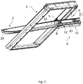
- a roof window arrangement according to a first embodiment of the invention is shown in an open and in a closed position.
- the roof window arrangement shown comprises a roof window with a stationary frame 1, connected to the stationary frame 1 is a sash 2 carrying a pane 3.
- the sash 2 is connected to the stationary frame 1 by means of a set of hinges 5 and configured to assume at least an open position and a closed position by rotation about a hinge axis substantially parallel to the top member 21 of the sash 2.
- the sash 2 comprises at least a top member 21 defining a width of the sash, two mutually parallel side members 22, 23 defining a length of the sash, and a bottom member 20 parallel to the top member 21.
- the manual operating assembly 4 is mounted on the sash 2 .
- the manual operating assembly 4 has a handle portion 41 located at the top member 21 of the sash 2 and has a longitudinal extension substantially in parallel with the top member 21 of the sash 2.
- the sash 2 is provided with a schematically shown electrical operating assembly 6, configured to at least assist in operation of the sash 2 between the open and the closed position.
- the electrical operating assembly 6 may be configured to control the manual operation assembly 4 in a manner known per se.
- the manual operating assembly 4 here comprises a ventilation flap, which is pivotally connected to the sash top member 21 by a flap hinge, or set of flap hinges (not visible) located in a flap hinge recess 26.
- a pivotal connection allows the manual operating assembly 4 to rotate about an axis in a plane parallel to the plane of the pane 3.
- the manual operating assembly in the form of the ventilation flap 4 is in the shown embodiment controlled by the handle portion 41, where the handle portion 41 is connected to a closure portion 43 via a connection portion 42 extending between the closure portion 43 and the handle portion such that a distance is provided between the handle portion 41 and the closure portion 43.
- the closure portion 43 is here configured to selectively close off and open up passage through at least one ventilation opening 25 at the sash top member 21.
- a lock mechanism 27 is provided to be operated by the manual operating assembly 4; alternatively no lock mechanism is provided and the locking is provided for in other manners.
- the lock mechanism 27 is connected to the closure portion 43 and the sash top member 21, allowing to lock in place the manual operating assembly 4 in relation to the sash top member 21 and thus the sash 2 relative to the frame. It is noted that while the manual operating assembly 4 is configured to rotate about a hinge axis provided by the flap hinge or hinges, the handle portion 41 is fixed, and not rotatable, relative to the other parts of the manual operating assembly 4, i.e. the connection portion 42 and the closure portion 43.
- the manual operating assembly 4 is provided with a left-hand end console 421 and a counterpart right-hand end console at the opposite end, the distance between the left-hand end console 421 and the right-hand end console 422 defining a longitudinal extension, or length, of the manual operating assembly.
- the handle portion 41 is formed as a handle bar profile 411, but may be formed to take any shape suitable for being gripped or grabbed.
- the handle bar profile 411 can in principle be made by any suitable material and manufacturing technology, but is here provided as an extruded profile of a metal material, allowing for the creation of a wide variety of cross-sectional profiles.
- the electrical operating assembly 6 of the roof window arrangement is configured to cooperate with an integrated control unit 8 as will be described in further detail below.
- the presence of an integrated control unit 8 does not exclude the presence of a remote control unit 10' as in the prior art, as long as suitable pairing and correspondence of the units is ensured.
- the integrated control unit 8 comprises a control part 82 formed in the handle portion 41 of the manual operating assembly 4. In cases in which there are more than one handle portion, the integrated control unit 8 may be provided in only one of the handle portions.
- the integrated control unit could in principle be provided as a separate part and then connected in an integral manner with the handle portion.
- the control part 82 of the integrated control unit 8 is comprised in an interactive surface segment 44 of the handle portion 41 of the manual operating assembly 4.
- control part 82 comprises a longitudinally extending touch panel 821 with a series of icons 821a.
- the icons 821a will be described in further detail below in connection with the embodiment shown in Fig. 7 .
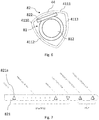
- the handle bar profile 411 has a generally closed configuration defining a hollow interior 413. Solid configurations are conceivable as well.
- the cross-section of the handle bar profile 411 shown is triangular, and defines a front edge section 4110, a top section 4111, a bottom section 4112 and a back section 4113.
- Other cross-sections of the handle bar profile 411 such as rectangular, square, rounded including circular, elliptical, and oval, would also be possible.
- control part 82 including the touch panel 821 of the integrated control unit 8 is located in the top section 4111, but other positions are possible and may be selected in accordance with the location of the roof window arrangement.
- the touch panel of the control portion extends continuously over at least two sections. This renders the roof window arrangement more versatile as regards positioning, as the user will be able to see the touch panel from various angles.
- the touch panel may over the top section 4111 and the bottom section 4112 including a front edge section 4110 between the top section 4111 and the bottom section 4112.
- the integrated control unit 8 in the embodiment shown comprises a base part 81 in integral connection with the handle portion 41, or at least one of the handle portions, of the manual operating assembly 4.
- the base part 81 may be provided as a separate component which is then connected to the handle portion 41, for instance to the control part 82.
- the base part 81 in which the base part 81 is accommodated in the hollow interior 413 of the handle bar profile 411, the base part 81 is typically slid in from one end of the handle bar profile 411 during manufacture.
- a print circuit board 822 is accommodated in the handle portion 41, below the touch panel 821.
- Power means for the remote control unit 8 may also be comprised in the handle portion 41 of the manual operating assembly 4.
- the power means may include a connector to be connected to the main power supply, or the power means for the remote control unit may comprise batteries configured to be received in a battery compartment 812 in the base part 81 accommodated in the hollow interior 413 of the handle bar profile 411.
- Batteries may be installed from the end of the handle portion, or slid in through a slot (not shown).
- a USB stick may be provided at the end or back side of the handle portion, for instance for charging of batteries, or for connecting accessories including auxiliary equipment. This may include solar cells.
- the control part 82 may be configured in any suitable manner allowing proper operation of the integrated control unit 8.
- the interactive surface segment 44 has a reduced material thickness relative to the remaining parts of the handle bar profile 411. This allows for improved connectivity between the surface of the handle portion and the control part of the integrated control unit.
- Fig. 7 is a plan view of a touch panel 821 of an integrated control unit 8 in another embodiment according to the invention.
- the touch panel 821 can have one or more icons 821a, preferably the touch panel 821 is equipped with icons 821a symbolizing opening of the window, closing of the window, ventilation, and if the roof window arrangement includes a screening assembly the icons 821a can also cover selection and control of an exterior screening assembly, selection and control of an interior screening assembly. It is noted that the selection and control of the interior screening assembly is carried out by means of a single icon which in turn is different from the icon for selecting and controlling the exterior screening assembly, or for operating the window itself. More icons 821a may be added to add to the functionality of the integrated control unit 8.
- the icons 821a for opening and closing the window may further include a range of icons 821a, each symbolizing a different opening or closing degree of the window.
- the design of icons 821a shown is only an example, different designs for icons may be envisioned.
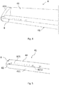
- Figs 8 and 9 show isometric views of a manual operating assembly 104 and 304, respectively, with the remote control unit 8 in a second and third embodiment of the roof window arrangement according to the invention.
- the manual operating assembly 104 in addition to the handle portion 141 has a closure portion 143 connected to the handle portion 141 via a connection portion 142 extending between the closure portion 143 and the handle portion 141, such that a distance is provided between the handle portion 141 and the closure portion 143.
- the closure portion 143 is, as in the first embodiment, configured to selectively close off and open up passage through at least one ventilation opening at the sash top member.
- the handle bar profile 1411 has a generally open, inverted U-shaped configuration in which the handle portion 141 and the closure portion 143 form legs of the U-shape and the connection portion 142 forms a base of the U-shape.
- the manual operating assembly 104 is configured to rotate about a hinge axis provided by the flap hinge or hinges, and the handle portion 141 is fixed, i.e. not rotatable, relative to the other parts of the manual operating assembly 104, i.e. the connection portion 142 and the closure portion 143.
- the handle portion 341 does not extend throughout the whole width of the sash.
- the handle portion 341 has a smaller longitudinal extension than the width of the sash 2, preferably in the range of 20 to 40% of the width of the sash 2.
- the manual operating assembly 4 may include a lock mechanism connected to the handle portion 341 and to the sash top member 21, with the lock mechanism being arranged to lock in place the handle portion 341 in relation to the sash top member 21.
- the roof window arrangement may also include a set of appliance members configured to cooperate with the roof window, and/or with the manual operating assembly 4, and/or with the electrical operating assembly 6 and/or with other appliance members of the set of appliance members.
- the integrated control unit 8 further comprises voice receiving means configured to cooperate with the electrical operating assembly 6.
- the integrated control unit 8 may further comprise network means configured to cooperate with the electrical operating assembly 6, the network means being communicatively connectable to a wireless transmit / receive unit.
- Sensors configured to detect environmental conditions, including light, temperature, movement, sound, smoke etc. may be provided.
- sensors may for instance include a gesture sensor allowing the user to activate the functionality of the roof window arrangement by a certain movement pattern, for instance clapping or waving. Since such functionality may include opening of the roof window, it is of course necessary to ascertain that the sensor is not able to be triggered by movements from the exterior of the building, i.e. from the outer side of the roof window.
- the integrated control unit may also be provided with backlight illumination means. If sensors are provided, then the backlight illumination means may be configured to cooperate with the sensors.
- the handle portion, or at least one of the handle portions, of the manual operating assembly may be provided with light indicators configured to cooperate with the sensors.
Landscapes
- Engineering & Computer Science (AREA)
- Architecture (AREA)
- Civil Engineering (AREA)
- Structural Engineering (AREA)
- Power-Operated Mechanisms For Wings (AREA)
Applications Claiming Priority (1)
| Application Number | Priority Date | Filing Date | Title |
|---|---|---|---|
| DKPA201970477 | 2019-07-24 |
Publications (2)
| Publication Number | Publication Date |
|---|---|
| EP3770355A1 true EP3770355A1 (de) | 2021-01-27 |
| EP3770355B1 EP3770355B1 (de) | 2022-06-29 |
Family
ID=71614764
Family Applications (1)
| Application Number | Title | Priority Date | Filing Date |
|---|---|---|---|
| EP20185709.1A Active EP3770355B1 (de) | 2019-07-24 | 2020-07-14 | Dachfensteranordnung mit einer manuell bedienbaren anordnung mit einem integrierten steuerteil |
Country Status (1)
| Country | Link |
|---|---|
| EP (1) | EP3770355B1 (de) |
Cited By (1)
| Publication number | Priority date | Publication date | Assignee | Title |
|---|---|---|---|---|
| PL444366A1 (pl) * | 2023-04-11 | 2024-10-14 | Fakro Pp Spółka Z Ograniczoną Odpowiedzialnością | Okno dachowe z listwą |
Citations (3)
| Publication number | Priority date | Publication date | Assignee | Title |
|---|---|---|---|---|
| EP1856358A1 (de) * | 2005-02-28 | 2007-11-21 | VKR Holding A/S | Lösbare verbindung |
| EP2957700A1 (de) * | 2014-04-29 | 2015-12-23 | VKR Holding A/S | Dachfensterantrieb |
| EP3235993A1 (de) | 2016-04-18 | 2017-10-25 | VKR Holding A/S | Fensteraktuator mit hinderniserkennung |
-
2020
- 2020-07-14 EP EP20185709.1A patent/EP3770355B1/de active Active
Patent Citations (3)
| Publication number | Priority date | Publication date | Assignee | Title |
|---|---|---|---|---|
| EP1856358A1 (de) * | 2005-02-28 | 2007-11-21 | VKR Holding A/S | Lösbare verbindung |
| EP2957700A1 (de) * | 2014-04-29 | 2015-12-23 | VKR Holding A/S | Dachfensterantrieb |
| EP3235993A1 (de) | 2016-04-18 | 2017-10-25 | VKR Holding A/S | Fensteraktuator mit hinderniserkennung |
Cited By (1)
| Publication number | Priority date | Publication date | Assignee | Title |
|---|---|---|---|---|
| PL444366A1 (pl) * | 2023-04-11 | 2024-10-14 | Fakro Pp Spółka Z Ograniczoną Odpowiedzialnością | Okno dachowe z listwą |
Also Published As
| Publication number | Publication date |
|---|---|
| EP3770355B1 (de) | 2022-06-29 |
Similar Documents
| Publication | Publication Date | Title |
|---|---|---|
| US20090139052A1 (en) | Handle element | |
| US11015389B2 (en) | Interlocking pivotable fascia for motorized window treatment | |
| US9482032B2 (en) | System for changing a locking state | |
| CN105133998B (zh) | 动作模式切换装置 | |
| EP3770355B1 (de) | Dachfensteranordnung mit einer manuell bedienbaren anordnung mit einem integrierten steuerteil | |
| EP1821052A2 (de) | Kühlschrank mit einer Tür mit integriertem Bedienfeld | |
| EP2547855B1 (de) | Ventilationfenster oder ventilationtüren | |
| EP3770354B1 (de) | Dachfensteranordnung mit einer manuell bedienbaren anordnung mit einem geräteteil | |
| KR200380529Y1 (ko) | 전동실린더개폐식 투명루버 | |
| EP3770356B1 (de) | Aufrüstsatz für ein dachfenster mit einer manuell bedienbaren anordnung und dachfensteranordnung mit einem solchen aufrüstsatz | |
| CN211201644U (zh) | 一种可控制开合的通风窗扉 | |
| JPH05206654A (ja) | 機器の動作制御ボックス | |
| CN207965855U (zh) | 红外触摸屏结构 | |
| JP2009044148A (ja) | 音響器機の前面パネルの開閉装置 | |
| KR102593019B1 (ko) | 잠금 기능을 갖는 창호용 핸들 | |
| EP3124732B1 (de) | Fenster mit einer öffnungsdrossel mit einer greifvorrichtung | |
| JP3693645B2 (ja) | 電動ブラインド | |
| EP4108869B1 (de) | Fahrzeugtürgriffanordnung | |
| US7727338B2 (en) | Dishwasher machine with door and handle element | |
| EP4435331A1 (de) | Abzugshaube für kochdünsten | |
| KR20110139435A (ko) | 문의 중간부에 장착하는 자동문 작동장치 | |
| JP6176927B2 (ja) | 照明ユニット、及び、該照明ユニットを備えた開口部装置 | |
| JP4088580B2 (ja) | 施錠機構付き引手装置、およびこれを備えたサッシ窓 | |
| JP2018104916A5 (de) | ||
| KR101285659B1 (ko) | 세탁 장치 |
Legal Events
| Date | Code | Title | Description |
|---|---|---|---|
| PUAI | Public reference made under article 153(3) epc to a published international application that has entered the european phase |
Free format text: ORIGINAL CODE: 0009012 |
|
| STAA | Information on the status of an ep patent application or granted ep patent |
Free format text: STATUS: THE APPLICATION HAS BEEN PUBLISHED |
|
| AK | Designated contracting states |
Kind code of ref document: A1 Designated state(s): AL AT BE BG CH CY CZ DE DK EE ES FI FR GB GR HR HU IE IS IT LI LT LU LV MC MK MT NL NO PL PT RO RS SE SI SK SM TR |
|
| AX | Request for extension of the european patent |
Extension state: BA ME |
|
| STAA | Information on the status of an ep patent application or granted ep patent |
Free format text: STATUS: REQUEST FOR EXAMINATION WAS MADE |
|
| 17P | Request for examination filed |
Effective date: 20210727 |
|
| RBV | Designated contracting states (corrected) |
Designated state(s): AL AT BE BG CH CY CZ DE DK EE ES FI FR GB GR HR HU IE IS IT LI LT LU LV MC MK MT NL NO PL PT RO RS SE SI SK SM TR |
|
| GRAP | Despatch of communication of intention to grant a patent |
Free format text: ORIGINAL CODE: EPIDOSNIGR1 |
|
| STAA | Information on the status of an ep patent application or granted ep patent |
Free format text: STATUS: GRANT OF PATENT IS INTENDED |
|
| RIC1 | Information provided on ipc code assigned before grant |
Ipc: E05B 1/00 20060101ALI20220103BHEP Ipc: E05F 15/616 20150101ALI20220103BHEP Ipc: E04F 11/06 20060101ALI20220103BHEP Ipc: E04D 13/035 20060101ALI20220103BHEP Ipc: E04D 13/03 20060101AFI20220103BHEP |
|
| INTG | Intention to grant announced |
Effective date: 20220120 |
|
| RIN1 | Information on inventor provided before grant (corrected) |
Inventor name: THOMSEN, CARSTEN Inventor name: ULLERSTED, THOMAS Inventor name: NIELSEN, KRISTIAN OERNSVIG |
|
| GRAS | Grant fee paid |
Free format text: ORIGINAL CODE: EPIDOSNIGR3 |
|
| GRAA | (expected) grant |
Free format text: ORIGINAL CODE: 0009210 |
|
| STAA | Information on the status of an ep patent application or granted ep patent |
Free format text: STATUS: THE PATENT HAS BEEN GRANTED |
|
| AK | Designated contracting states |
Kind code of ref document: B1 Designated state(s): AL AT BE BG CH CY CZ DE DK EE ES FI FR GB GR HR HU IE IS IT LI LT LU LV MC MK MT NL NO PL PT RO RS SE SI SK SM TR |
|
| REG | Reference to a national code |
Ref country code: CH Ref legal event code: EP |
|
| REG | Reference to a national code |
Ref country code: AT Ref legal event code: REF Ref document number: 1501453 Country of ref document: AT Kind code of ref document: T Effective date: 20220715 |
|
| REG | Reference to a national code |
Ref country code: IE Ref legal event code: FG4D |
|
| REG | Reference to a national code |
Ref country code: DE Ref legal event code: R096 Ref document number: 602020003734 Country of ref document: DE |
|
| REG | Reference to a national code |
Ref country code: LT Ref legal event code: MG9D |
|
| PG25 | Lapsed in a contracting state [announced via postgrant information from national office to epo] |
Ref country code: SE Free format text: LAPSE BECAUSE OF FAILURE TO SUBMIT A TRANSLATION OF THE DESCRIPTION OR TO PAY THE FEE WITHIN THE PRESCRIBED TIME-LIMIT Effective date: 20220629 Ref country code: NO Free format text: LAPSE BECAUSE OF FAILURE TO SUBMIT A TRANSLATION OF THE DESCRIPTION OR TO PAY THE FEE WITHIN THE PRESCRIBED TIME-LIMIT Effective date: 20220929 Ref country code: LT Free format text: LAPSE BECAUSE OF FAILURE TO SUBMIT A TRANSLATION OF THE DESCRIPTION OR TO PAY THE FEE WITHIN THE PRESCRIBED TIME-LIMIT Effective date: 20220629 Ref country code: HR Free format text: LAPSE BECAUSE OF FAILURE TO SUBMIT A TRANSLATION OF THE DESCRIPTION OR TO PAY THE FEE WITHIN THE PRESCRIBED TIME-LIMIT Effective date: 20220629 Ref country code: GR Free format text: LAPSE BECAUSE OF FAILURE TO SUBMIT A TRANSLATION OF THE DESCRIPTION OR TO PAY THE FEE WITHIN THE PRESCRIBED TIME-LIMIT Effective date: 20220930 Ref country code: FI Free format text: LAPSE BECAUSE OF FAILURE TO SUBMIT A TRANSLATION OF THE DESCRIPTION OR TO PAY THE FEE WITHIN THE PRESCRIBED TIME-LIMIT Effective date: 20220629 Ref country code: BG Free format text: LAPSE BECAUSE OF FAILURE TO SUBMIT A TRANSLATION OF THE DESCRIPTION OR TO PAY THE FEE WITHIN THE PRESCRIBED TIME-LIMIT Effective date: 20220929 |
|
| REG | Reference to a national code |
Ref country code: NL Ref legal event code: MP Effective date: 20220629 |
|
| REG | Reference to a national code |
Ref country code: AT Ref legal event code: MK05 Ref document number: 1501453 Country of ref document: AT Kind code of ref document: T Effective date: 20220629 |
|
| PG25 | Lapsed in a contracting state [announced via postgrant information from national office to epo] |
Ref country code: RS Free format text: LAPSE BECAUSE OF FAILURE TO SUBMIT A TRANSLATION OF THE DESCRIPTION OR TO PAY THE FEE WITHIN THE PRESCRIBED TIME-LIMIT Effective date: 20220629 Ref country code: LV Free format text: LAPSE BECAUSE OF FAILURE TO SUBMIT A TRANSLATION OF THE DESCRIPTION OR TO PAY THE FEE WITHIN THE PRESCRIBED TIME-LIMIT Effective date: 20220629 |
|
| PG25 | Lapsed in a contracting state [announced via postgrant information from national office to epo] |
Ref country code: NL Free format text: LAPSE BECAUSE OF FAILURE TO SUBMIT A TRANSLATION OF THE DESCRIPTION OR TO PAY THE FEE WITHIN THE PRESCRIBED TIME-LIMIT Effective date: 20220629 |
|
| PG25 | Lapsed in a contracting state [announced via postgrant information from national office to epo] |
Ref country code: SM Free format text: LAPSE BECAUSE OF FAILURE TO SUBMIT A TRANSLATION OF THE DESCRIPTION OR TO PAY THE FEE WITHIN THE PRESCRIBED TIME-LIMIT Effective date: 20220629 Ref country code: SK Free format text: LAPSE BECAUSE OF FAILURE TO SUBMIT A TRANSLATION OF THE DESCRIPTION OR TO PAY THE FEE WITHIN THE PRESCRIBED TIME-LIMIT Effective date: 20220629 Ref country code: RO Free format text: LAPSE BECAUSE OF FAILURE TO SUBMIT A TRANSLATION OF THE DESCRIPTION OR TO PAY THE FEE WITHIN THE PRESCRIBED TIME-LIMIT Effective date: 20220629 Ref country code: PT Free format text: LAPSE BECAUSE OF FAILURE TO SUBMIT A TRANSLATION OF THE DESCRIPTION OR TO PAY THE FEE WITHIN THE PRESCRIBED TIME-LIMIT Effective date: 20221031 Ref country code: ES Free format text: LAPSE BECAUSE OF FAILURE TO SUBMIT A TRANSLATION OF THE DESCRIPTION OR TO PAY THE FEE WITHIN THE PRESCRIBED TIME-LIMIT Effective date: 20220629 Ref country code: EE Free format text: LAPSE BECAUSE OF FAILURE TO SUBMIT A TRANSLATION OF THE DESCRIPTION OR TO PAY THE FEE WITHIN THE PRESCRIBED TIME-LIMIT Effective date: 20220629 Ref country code: AT Free format text: LAPSE BECAUSE OF FAILURE TO SUBMIT A TRANSLATION OF THE DESCRIPTION OR TO PAY THE FEE WITHIN THE PRESCRIBED TIME-LIMIT Effective date: 20220629 |
|
| PG25 | Lapsed in a contracting state [announced via postgrant information from national office to epo] |
Ref country code: PL Free format text: LAPSE BECAUSE OF FAILURE TO SUBMIT A TRANSLATION OF THE DESCRIPTION OR TO PAY THE FEE WITHIN THE PRESCRIBED TIME-LIMIT Effective date: 20220629 Ref country code: IS Free format text: LAPSE BECAUSE OF FAILURE TO SUBMIT A TRANSLATION OF THE DESCRIPTION OR TO PAY THE FEE WITHIN THE PRESCRIBED TIME-LIMIT Effective date: 20221029 |
|
| REG | Reference to a national code |
Ref country code: BE Ref legal event code: MM Effective date: 20220731 |
|
| REG | Reference to a national code |
Ref country code: DE Ref legal event code: R097 Ref document number: 602020003734 Country of ref document: DE |
|
| PG25 | Lapsed in a contracting state [announced via postgrant information from national office to epo] |
Ref country code: MC Free format text: LAPSE BECAUSE OF FAILURE TO SUBMIT A TRANSLATION OF THE DESCRIPTION OR TO PAY THE FEE WITHIN THE PRESCRIBED TIME-LIMIT Effective date: 20220629 Ref country code: AL Free format text: LAPSE BECAUSE OF FAILURE TO SUBMIT A TRANSLATION OF THE DESCRIPTION OR TO PAY THE FEE WITHIN THE PRESCRIBED TIME-LIMIT Effective date: 20220629 |
|
| PG25 | Lapsed in a contracting state [announced via postgrant information from national office to epo] |
Ref country code: LU Free format text: LAPSE BECAUSE OF NON-PAYMENT OF DUE FEES Effective date: 20220714 Ref country code: DK Free format text: LAPSE BECAUSE OF FAILURE TO SUBMIT A TRANSLATION OF THE DESCRIPTION OR TO PAY THE FEE WITHIN THE PRESCRIBED TIME-LIMIT Effective date: 20220629 Ref country code: CZ Free format text: LAPSE BECAUSE OF FAILURE TO SUBMIT A TRANSLATION OF THE DESCRIPTION OR TO PAY THE FEE WITHIN THE PRESCRIBED TIME-LIMIT Effective date: 20220629 |
|
| PLBE | No opposition filed within time limit |
Free format text: ORIGINAL CODE: 0009261 |
|
| STAA | Information on the status of an ep patent application or granted ep patent |
Free format text: STATUS: NO OPPOSITION FILED WITHIN TIME LIMIT |
|
| PG25 | Lapsed in a contracting state [announced via postgrant information from national office to epo] |
Ref country code: BE Free format text: LAPSE BECAUSE OF NON-PAYMENT OF DUE FEES Effective date: 20220731 |
|
| 26N | No opposition filed |
Effective date: 20230330 |
|
| PG25 | Lapsed in a contracting state [announced via postgrant information from national office to epo] |
Ref country code: IE Free format text: LAPSE BECAUSE OF NON-PAYMENT OF DUE FEES Effective date: 20220714 |
|
| PG25 | Lapsed in a contracting state [announced via postgrant information from national office to epo] |
Ref country code: SI Free format text: LAPSE BECAUSE OF FAILURE TO SUBMIT A TRANSLATION OF THE DESCRIPTION OR TO PAY THE FEE WITHIN THE PRESCRIBED TIME-LIMIT Effective date: 20220629 |
|
| PG25 | Lapsed in a contracting state [announced via postgrant information from national office to epo] |
Ref country code: IT Free format text: LAPSE BECAUSE OF FAILURE TO SUBMIT A TRANSLATION OF THE DESCRIPTION OR TO PAY THE FEE WITHIN THE PRESCRIBED TIME-LIMIT Effective date: 20220629 |
|
| REG | Reference to a national code |
Ref country code: CH Ref legal event code: PL |
|
| PG25 | Lapsed in a contracting state [announced via postgrant information from national office to epo] |
Ref country code: MK Free format text: LAPSE BECAUSE OF FAILURE TO SUBMIT A TRANSLATION OF THE DESCRIPTION OR TO PAY THE FEE WITHIN THE PRESCRIBED TIME-LIMIT Effective date: 20220629 Ref country code: CY Free format text: LAPSE BECAUSE OF FAILURE TO SUBMIT A TRANSLATION OF THE DESCRIPTION OR TO PAY THE FEE WITHIN THE PRESCRIBED TIME-LIMIT Effective date: 20220629 Ref country code: CH Free format text: LAPSE BECAUSE OF NON-PAYMENT OF DUE FEES Effective date: 20230731 |
|
| PG25 | Lapsed in a contracting state [announced via postgrant information from national office to epo] |
Ref country code: HU Free format text: LAPSE BECAUSE OF FAILURE TO SUBMIT A TRANSLATION OF THE DESCRIPTION OR TO PAY THE FEE WITHIN THE PRESCRIBED TIME-LIMIT; INVALID AB INITIO Effective date: 20200714 |
|
| PG25 | Lapsed in a contracting state [announced via postgrant information from national office to epo] |
Ref country code: MT Free format text: LAPSE BECAUSE OF FAILURE TO SUBMIT A TRANSLATION OF THE DESCRIPTION OR TO PAY THE FEE WITHIN THE PRESCRIBED TIME-LIMIT Effective date: 20220629 |
|
| PG25 | Lapsed in a contracting state [announced via postgrant information from national office to epo] |
Ref country code: BG Free format text: LAPSE BECAUSE OF FAILURE TO SUBMIT A TRANSLATION OF THE DESCRIPTION OR TO PAY THE FEE WITHIN THE PRESCRIBED TIME-LIMIT Effective date: 20220629 |
|
| PG25 | Lapsed in a contracting state [announced via postgrant information from national office to epo] |
Ref country code: BG Free format text: LAPSE BECAUSE OF FAILURE TO SUBMIT A TRANSLATION OF THE DESCRIPTION OR TO PAY THE FEE WITHIN THE PRESCRIBED TIME-LIMIT Effective date: 20220629 |
|
| PGFP | Annual fee paid to national office [announced via postgrant information from national office to epo] |
Ref country code: GB Payment date: 20250605 Year of fee payment: 6 |
|
| PGFP | Annual fee paid to national office [announced via postgrant information from national office to epo] |
Ref country code: FR Payment date: 20250623 Year of fee payment: 6 |
|
| PGFP | Annual fee paid to national office [announced via postgrant information from national office to epo] |
Ref country code: DE Payment date: 20250604 Year of fee payment: 6 |
|
| PG25 | Lapsed in a contracting state [announced via postgrant information from national office to epo] |
Ref country code: TR Free format text: LAPSE BECAUSE OF FAILURE TO SUBMIT A TRANSLATION OF THE DESCRIPTION OR TO PAY THE FEE WITHIN THE PRESCRIBED TIME-LIMIT Effective date: 20220629 |