EP3770534A1 - Dispositif et procédé d'aération d'une pompe a chaleur - Google Patents
Dispositif et procédé d'aération d'une pompe a chaleur Download PDFInfo
- Publication number
- EP3770534A1 EP3770534A1 EP20187126.6A EP20187126A EP3770534A1 EP 3770534 A1 EP3770534 A1 EP 3770534A1 EP 20187126 A EP20187126 A EP 20187126A EP 3770534 A1 EP3770534 A1 EP 3770534A1
- Authority
- EP
- European Patent Office
- Prior art keywords
- working fluid
- air
- housing
- heat
- electronics
- Prior art date
- Legal status (The legal status is an assumption and is not a legal conclusion. Google has not performed a legal analysis and makes no representation as to the accuracy of the status listed.)
- Withdrawn
Links
Images
Classifications
-
- F—MECHANICAL ENGINEERING; LIGHTING; HEATING; WEAPONS; BLASTING
- F25—REFRIGERATION OR COOLING; COMBINED HEATING AND REFRIGERATION SYSTEMS; HEAT PUMP SYSTEMS; MANUFACTURE OR STORAGE OF ICE; LIQUEFACTION SOLIDIFICATION OF GASES
- F25B—REFRIGERATION MACHINES, PLANTS OR SYSTEMS; COMBINED HEATING AND REFRIGERATION SYSTEMS; HEAT PUMP SYSTEMS
- F25B25/00—Machines, plants or systems, using a combination of modes of operation covered by two or more of the groups F25B1/00 - F25B23/00
- F25B25/005—Machines, plants or systems, using a combination of modes of operation covered by two or more of the groups F25B1/00 - F25B23/00 using primary and secondary systems
-
- F—MECHANICAL ENGINEERING; LIGHTING; HEATING; WEAPONS; BLASTING
- F25—REFRIGERATION OR COOLING; COMBINED HEATING AND REFRIGERATION SYSTEMS; HEAT PUMP SYSTEMS; MANUFACTURE OR STORAGE OF ICE; LIQUEFACTION SOLIDIFICATION OF GASES
- F25B—REFRIGERATION MACHINES, PLANTS OR SYSTEMS; COMBINED HEATING AND REFRIGERATION SYSTEMS; HEAT PUMP SYSTEMS
- F25B49/00—Arrangement or mounting of control or safety devices
- F25B49/005—Arrangement or mounting of control or safety devices of safety devices
-
- F—MECHANICAL ENGINEERING; LIGHTING; HEATING; WEAPONS; BLASTING
- F25—REFRIGERATION OR COOLING; COMBINED HEATING AND REFRIGERATION SYSTEMS; HEAT PUMP SYSTEMS; MANUFACTURE OR STORAGE OF ICE; LIQUEFACTION SOLIDIFICATION OF GASES
- F25B—REFRIGERATION MACHINES, PLANTS OR SYSTEMS; COMBINED HEATING AND REFRIGERATION SYSTEMS; HEAT PUMP SYSTEMS
- F25B2339/00—Details of evaporators; Details of condensers
- F25B2339/04—Details of condensers
- F25B2339/047—Water-cooled condensers
Definitions
- the invention relates to irregular states in refrigeration circuits in which a working fluid acting as a refrigerant is guided in a thermodynamic cycle, such as the Rankine cycle, and to their safety device.
- thermodynamic cycle such as the Rankine cycle
- These are mainly heat pumps installed indoors, but also air conditioning and cooling devices such as those commonly used in residential buildings.
- Residential buildings are understood to mean private houses, apartment complexes, hospitals, hotel facilities, restaurants and combined residential and commercial buildings in which people live and work permanently, in contrast to mobile devices such as car air conditioning systems or transport boxes, or industrial systems or medical devices. What these cycle processes have in common is that they generate useful heat or useful cooling using energy and form heat displacement systems.
- thermodynamic cycle processes used have been known for a long time, as have the safety problems that can arise when using suitable working fluids. Apart from water, the most popular working fluids of the time are flammable and poisonous. In the past century, they led to the development of safety refrigerants, which consisted of fluorinated hydrocarbons. However, it turned out that these safety refrigerants lead to global warming and that their safety-related harmlessness led to constructive inattention. Up to 70% of the turnover was accounted for by the need to refill leaky systems and their leakage losses, which was accepted as long as this was perceived as economically justifiable in individual cases and encouraged the need for replacement.
- Today's refrigeration circuits are equipped with these safety refrigerants of safety class A1, i.e. they are non-toxic and non-flammable.
- the most common refrigerants in the field of heat pump applications are the refrigerants R134a, R407C and R410A, all of them fluorocarbon compounds.
- the use of these refrigerants was not subject to any restrictions until January 2015, the introduction of the F-Gas Regulation (EU) 517/2014 on January 01, 2015 will in future restrict the use of fluorocarbon refrigerants via quantity restrictions in the European Union in such a way that the prices of previous refrigerants will rise significantly.
- the aim of the F-gas regulation is the medium-term ban of greenhouse gas-promoting refrigerants and the replacement by natural refrigerants or chemical refrigerants with a significantly reduced global warming potential.
- the EN 378 standard and its specifications for installation are also relevant.
- refrigerants belong to the group of flammable or toxic refrigerants, especially the technically most promising refrigerants such as R290 (propane) and R1270 (propylene).
- heat pumps installed outside differ considerably from those installed inside. While protection from the weather in the form of rain, frost and icing dominates with heat pumps installed outdoors, installation indoors is similar to the situation in data centers.
- the electronic components are housed separately and cooled with air or with ambient air.
- a ventilation system for the electronics and a ventilating flushing system are provided around the heat pump apparatus, which are operated independently of one another.
- the DE 44 13 130 C2 describes a cooling device for a switch cabinet, in which cold generating devices and a secondary circuit are housed and separated from one another by a gas-impermeable partition from the interior of the switch cabinet.
- a cold brine circulates in the secondary circuit, which cools the contents of the control cabinet via a heat exchanger.
- the cold brine is cooled by the primary circuit in which the refrigerant circulates in a known manner.
- the waste heat is taken from the primary circuit in the usual way in a condenser DE 44 13 130 C2 teaches to dissipate heat to the environment.
- the heat pump must provide heat on demand, which can either be used for heating or to generate hot water, but it should be recycled. In summer there is no heating, but heat can be used in long-term storage or for pools. The heat can also come from cooling the living space. The focus of heat pumps is therefore on using the heat generated. As a rule, this heat is obtained from the surroundings of the house, be it from outside air or groundwater or from geothermal extraction. Due to the often considerable waste heat from the electronics of inverters and In the present case, the control electronics of heat pumps should also turn the waste heat into useful heat.
- the object of the invention is therefore to provide a safe device for simultaneous ventilation of the apparatus of the heat pump installed inside and the use of the heat from the electronics, which device no longer has the disadvantages described.
- a housing is referred to as a working fluid housing which includes all devices connected to the closed working fluid circuit and can include further devices, including a housing for the electronic devices.
- An electronics housing is a housing that contains all electronic devices, including the power electronics and the control electronics; it can also be divided, contain externally accessible slots or have an additional cooling device, e.g. water cooling or a heat pipe.
- a branch with at least two branches for air is provided in the outflow area after the electronics housing, one branch being returned to the working fluid casing and cooled there and the other branch having an outlet from the building.
- the branch is designed to be switchable, so that either one or the other branch is open and the other is closed.
- a closable air inlet opening is provided in the working fluid housing.
- a third branch for direct delivery of heating air into the installation room can also be provided.
- the branch that leads from the electronics housing back into the working fluid housing is open and the air inlet is closed. If a leak is detected, the air inlet opening is opened and the air branch into the working fluid housing is closed. In this case, the contaminated air is led into the open by the conveying fan and air from the building in which the heat pump is installed is sucked into the working fluid housing for flushing.
- the air inlet opening is equipped with a non-return device so that in the event of an overpressure situation due to a major leak, no contaminated air can get into the installation room.
- the conveyor fan is equipped with a battery that can provide an amount of energy that is sufficient in the event of a power failure to convey a volume of gas through the working fluid housing that is large enough to safely ventilate the entire working fluid without that an ignitable mixture is formed.
- a battery that can provide an amount of energy that is sufficient in the event of a power failure to convey a volume of gas through the working fluid housing that is large enough to safely ventilate the entire working fluid without that an ignitable mixture is formed.
- the specialist must provide the amount of energy to be provided depending on the installation conditions, the efficiency and the pressure loss of the discharge.
- the air which is normally returned to the working fluid housing, is cooled in the working fluid housing by being guided past a line leading from or to the evaporator before it is dispersed into the working fluid housing.
- the waste heat from the heat pump can be used as a heat source.
- this can also be done using a suitable heat exchanger.
- the heat exchanger can also be attached on the high pressure side of the working fluid or on the primary or secondary side of the heat transfer fluid, that is to say water or brine.
- the electronics housing is directly adjacent to the working fluid housing, preferably at the front, or is integrated therein. In this way, additional sound insulation can be achieved.
- a temperature sensor is provided at the air outlet of the electronics housing, which regulates the conveying fan speed and, if the control range is left, outputs an alarm.
- the alarm can also be provided that the system is then switched off or put into a secured state.
- speed monitoring or flow monitoring is also possible.
- a gas detector for flammable working fluid is provided at the air inlet of the electronics housing.
- this gas detector or another leakage detection system gives a positive signal, the air branching to the outlet from the building is switched, the air inlet is opened, the conveyor fan speed is set to the maximum value and an alarm is triggered.
- the waste heat from the electronics is used as a heat source for the useful heat of the heat pump, the heat being fed to the working fluid on the outflow side for pressure reduction in a heat exchanger.
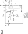
- Fig. 1 a simplified scheme of the air flow.
- Fig. 1 shows a heat pump based on a schematic diagram of a refrigeration circuit 1 with a compressor 2, a condenser 3, a pressure reduction 4 and an evaporator 5 in a working fluid housing 6 and a directly connected electronics housing 7.
- the refrigeration circuit 1 is operated with the flammable working fluid propane, which is also known as R290.
- a suction opening 8 with a gas detector 9 is provided, which is connected to the electronics housing 7.
- the air enters the air outlet 10 with the temperature sensor 11 from the electronics housing 7 and is conveyed by the conveying fan 12 to the air branch 13.
- the first branch guides the heated cooling air 14 via the circulating air line 15 to the heat exchanger 16 and then back again into the working fluid housing 6.
- the second branch leads out of the building as exhaust air 17 and is used when the signal at the gas detector 9 is positive.
- the air inlet opening 18, which is equipped with the non-return valve 19, is unlocked so that air can flow in from the building.
- the heat utilization of the waste heat from the electronics cooling results from the fact that the heated cooling air 14 is guided via the circulating air line 15 to the heat exchanger 16, where it gives off its heat to the liquid working fluid.
- the working fluid is preferably not yet evaporated; it is only preheated before it reaches the evaporator 5.
- the heat exchanger 16 serves as a preheater. An arrangement of the heat exchanger 16 after the evaporator 5 is also possible, but in terms of equipment is more complex, in such a case the heat exchanger 16 would act as a superheater.
- the heat obtained from the waste heat of the electronics is extracted in a known manner from the condenser 3, which is connected via an underfloor heating flow 21 and an underfloor heating return 22 to an underfloor heating 23, which is charged with a heat transfer fluid.
- the waste heat from the electronics can also be used directly for heating by providing the air branch 13 with three branches, of which the third branch leads as heating air 20 in normal operation directly into the installation room, if this is desired, in which case the Air inlet opening 18 is also opened.
Landscapes
- Engineering & Computer Science (AREA)
- Physics & Mathematics (AREA)
- Mechanical Engineering (AREA)
- Thermal Sciences (AREA)
- General Engineering & Computer Science (AREA)
- Other Air-Conditioning Systems (AREA)
Applications Claiming Priority (1)
| Application Number | Priority Date | Filing Date | Title |
|---|---|---|---|
| DE102019119871.2A DE102019119871A1 (de) | 2019-07-23 | 2019-07-23 | Vorrichtung und Verfahren zur Belüftung einer Wärmepumpe |
Publications (1)
| Publication Number | Publication Date |
|---|---|
| EP3770534A1 true EP3770534A1 (fr) | 2021-01-27 |
Family
ID=71741664
Family Applications (1)
| Application Number | Title | Priority Date | Filing Date |
|---|---|---|---|
| EP20187126.6A Withdrawn EP3770534A1 (fr) | 2019-07-23 | 2020-07-22 | Dispositif et procédé d'aération d'une pompe a chaleur |
Country Status (2)
| Country | Link |
|---|---|
| EP (1) | EP3770534A1 (fr) |
| DE (1) | DE102019119871A1 (fr) |
Cited By (1)
| Publication number | Priority date | Publication date | Assignee | Title |
|---|---|---|---|---|
| WO2024008231A1 (fr) * | 2022-07-05 | 2024-01-11 | Rittal Gmbh & Co. Kg | Ensemble armoire de commande à ventilation forcée |
Citations (7)
| Publication number | Priority date | Publication date | Assignee | Title |
|---|---|---|---|---|
| DE4445818A1 (de) | 1994-12-21 | 1995-06-14 | Bernhard Hilpert | Computergehäuse für den Industrie-Einsatz |
| DE4413130C2 (de) | 1994-04-19 | 1997-12-18 | Loh Kg Rittal Werk | Kühlgerät |
| DE69622294T2 (de) * | 1995-02-07 | 2003-03-06 | De'longhi S.P.A., Treviso | Verfahren und Anlage zur Klimatisierung mit wenigstens für die Ozonschicht unschädlicher Kühlflüssigkeit |
| DE102010002684A1 (de) * | 2010-03-09 | 2011-09-15 | Dürr Ecoclean GmbH | Verfahren und Vorrichtung zum Absaugen eines zündfähigen Absauggases |
| DE102014112545A1 (de) * | 2014-09-01 | 2016-03-03 | Denso Automotive Deutschland Gmbh | Kältemittelkreis-Kompaktaggregat für ein Kraftfahrzeug |
| DE202016103305U1 (de) * | 2016-06-22 | 2016-07-07 | Futron GmbH | Explosionsgeschützte Vorrichtung zum Temperieren von Wärmeträgerfluiden |
| WO2019113716A2 (fr) * | 2017-12-15 | 2019-06-20 | Mse Meili Ag | Lunette de procédé |
-
2019
- 2019-07-23 DE DE102019119871.2A patent/DE102019119871A1/de active Pending
-
2020
- 2020-07-22 EP EP20187126.6A patent/EP3770534A1/fr not_active Withdrawn
Patent Citations (7)
| Publication number | Priority date | Publication date | Assignee | Title |
|---|---|---|---|---|
| DE4413130C2 (de) | 1994-04-19 | 1997-12-18 | Loh Kg Rittal Werk | Kühlgerät |
| DE4445818A1 (de) | 1994-12-21 | 1995-06-14 | Bernhard Hilpert | Computergehäuse für den Industrie-Einsatz |
| DE69622294T2 (de) * | 1995-02-07 | 2003-03-06 | De'longhi S.P.A., Treviso | Verfahren und Anlage zur Klimatisierung mit wenigstens für die Ozonschicht unschädlicher Kühlflüssigkeit |
| DE102010002684A1 (de) * | 2010-03-09 | 2011-09-15 | Dürr Ecoclean GmbH | Verfahren und Vorrichtung zum Absaugen eines zündfähigen Absauggases |
| DE102014112545A1 (de) * | 2014-09-01 | 2016-03-03 | Denso Automotive Deutschland Gmbh | Kältemittelkreis-Kompaktaggregat für ein Kraftfahrzeug |
| DE202016103305U1 (de) * | 2016-06-22 | 2016-07-07 | Futron GmbH | Explosionsgeschützte Vorrichtung zum Temperieren von Wärmeträgerfluiden |
| WO2019113716A2 (fr) * | 2017-12-15 | 2019-06-20 | Mse Meili Ag | Lunette de procédé |
Cited By (1)
| Publication number | Priority date | Publication date | Assignee | Title |
|---|---|---|---|---|
| WO2024008231A1 (fr) * | 2022-07-05 | 2024-01-11 | Rittal Gmbh & Co. Kg | Ensemble armoire de commande à ventilation forcée |
Also Published As
| Publication number | Publication date |
|---|---|
| DE102019119871A1 (de) | 2021-01-28 |
Similar Documents
| Publication | Publication Date | Title |
|---|---|---|
| EP3792572B1 (fr) | Dispositif de rinçage de sécurité pour une pompe à chaleur | |
| EP3578895B1 (fr) | Dispositif et procédé pour le rinçage sûr et économique d'une enceinte | |
| EP3940314B1 (fr) | Dispositif de rinçage de sécurité pour une pompe à chaleur | |
| DE202016103305U1 (de) | Explosionsgeschützte Vorrichtung zum Temperieren von Wärmeträgerfluiden | |
| DE102016112851A1 (de) | Kältemodul | |
| EP3543629B1 (fr) | Boîtier étanche aux fuites pour un processus cyclique | |
| EP3581861A2 (fr) | Sorption du fluide | |
| DE102022123440A1 (de) | Serviceanschluss für ein Wärmepumpengehäuse | |
| EP4212784A1 (fr) | Extraction liquide d'hydrocarbures | |
| EP3770534A1 (fr) | Dispositif et procédé d'aération d'une pompe a chaleur | |
| EP3767186A1 (fr) | Dispositif de sécurité d'une unité de pompe à chaleur | |
| DE202024105901U1 (de) | Klimaanlageneinheit mit einem Leckentlüftungs-Inducer | |
| DE102019121496A1 (de) | Sicherheitsspülvorrichtung für eine Wärmepumpe | |
| DE102017126957A1 (de) | Kältekreis mit Leckagesicherung | |
| EP3719416B1 (fr) | Dispositif pour la mise en oeuvre sécurisée d'un cycle thermodynamique clausius-rankine tournant à gauche avec r290 comme fluide de travail | |
| DE112014000525T5 (de) | Heizsystem | |
| DE19635265C2 (de) | Kühl- und/oder Tiefkühlmöbel mit integriertem Kälteträgersystem | |
| EP4575332A1 (fr) | Adaptateur encapsulé pour pompe à chaleur divisée | |
| EP3486575B1 (fr) | Dispositif et procédé d'évacuation de sécurité du flux de travail | |
| DE102010028950A1 (de) | Vorrichtung zum Kühlen und Rechner-Racks | |
| EP3712531A1 (fr) | Dispositif de rinçage de sécurité pour une pompe à chaleur | |
| DE102012007089B4 (de) | Verfahren zur Kühlung von Luft im Innern eines Schaltschrankes und ein entsprechendes Kühlgerät für einen Schaltschrank | |
| EP3647684B1 (fr) | Zone de sécurité du condenseur | |
| DE102020119317A1 (de) | Odorierung von Arbeitsfluid | |
| EP4641110A1 (fr) | Pompe à chaleur divisée à boîtier modulaire et module hydraulique |
Legal Events
| Date | Code | Title | Description |
|---|---|---|---|
| PUAI | Public reference made under article 153(3) epc to a published international application that has entered the european phase |
Free format text: ORIGINAL CODE: 0009012 |
|
| STAA | Information on the status of an ep patent application or granted ep patent |
Free format text: STATUS: THE APPLICATION HAS BEEN PUBLISHED |
|
| AK | Designated contracting states |
Kind code of ref document: A1 Designated state(s): AL AT BE BG CH CY CZ DE DK EE ES FI FR GB GR HR HU IE IS IT LI LT LU LV MC MK MT NL NO PL PT RO RS SE SI SK SM TR |
|
| AX | Request for extension of the european patent |
Extension state: BA ME |
|
| STAA | Information on the status of an ep patent application or granted ep patent |
Free format text: STATUS: REQUEST FOR EXAMINATION WAS MADE |
|
| 17P | Request for examination filed |
Effective date: 20210716 |
|
| RBV | Designated contracting states (corrected) |
Designated state(s): AL AT BE BG CH CY CZ DE DK EE ES FI FR GB GR HR HU IE IS IT LI LT LU LV MC MK MT NL NO PL PT RO RS SE SI SK SM TR |
|
| STAA | Information on the status of an ep patent application or granted ep patent |
Free format text: STATUS: EXAMINATION IS IN PROGRESS |
|
| 17Q | First examination report despatched |
Effective date: 20250424 |
|
| STAA | Information on the status of an ep patent application or granted ep patent |
Free format text: STATUS: THE APPLICATION IS DEEMED TO BE WITHDRAWN |
|
| 18D | Application deemed to be withdrawn |
Effective date: 20250826 |