EP4575332A1 - Adaptateur encapsulé pour pompe à chaleur divisée - Google Patents
Adaptateur encapsulé pour pompe à chaleur divisée Download PDFInfo
- Publication number
- EP4575332A1 EP4575332A1 EP24219783.8A EP24219783A EP4575332A1 EP 4575332 A1 EP4575332 A1 EP 4575332A1 EP 24219783 A EP24219783 A EP 24219783A EP 4575332 A1 EP4575332 A1 EP 4575332A1
- Authority
- EP
- European Patent Office
- Prior art keywords
- refrigerant
- air
- adapter
- capsule housing
- capsule
- Prior art date
- Legal status (The legal status is an assumption and is not a legal conclusion. Google has not performed a legal analysis and makes no representation as to the accuracy of the status listed.)
- Pending
Links
Images




Classifications
-
- F—MECHANICAL ENGINEERING; LIGHTING; HEATING; WEAPONS; BLASTING
- F24—HEATING; RANGES; VENTILATING
- F24F—AIR-CONDITIONING; AIR-HUMIDIFICATION; VENTILATION; USE OF AIR CURRENTS FOR SCREENING
- F24F1/00—Room units for air-conditioning, e.g. separate or self-contained units or units receiving primary air from a central station
- F24F1/06—Separate outdoor units, e.g. outdoor unit to be linked to a separate room comprising a compressor and a heat exchanger
- F24F1/26—Refrigerant piping
- F24F1/32—Refrigerant piping for connecting the separate outdoor units to indoor units
-
- F—MECHANICAL ENGINEERING; LIGHTING; HEATING; WEAPONS; BLASTING
- F24—HEATING; RANGES; VENTILATING
- F24F—AIR-CONDITIONING; AIR-HUMIDIFICATION; VENTILATION; USE OF AIR CURRENTS FOR SCREENING
- F24F1/00—Room units for air-conditioning, e.g. separate or self-contained units or units receiving primary air from a central station
- F24F1/06—Separate outdoor units, e.g. outdoor unit to be linked to a separate room comprising a compressor and a heat exchanger
- F24F1/26—Refrigerant piping
- F24F1/34—Protection means thereof, e.g. covers for refrigerant pipes
-
- F—MECHANICAL ENGINEERING; LIGHTING; HEATING; WEAPONS; BLASTING
- F24—HEATING; RANGES; VENTILATING
- F24F—AIR-CONDITIONING; AIR-HUMIDIFICATION; VENTILATION; USE OF AIR CURRENTS FOR SCREENING
- F24F11/00—Control or safety arrangements
- F24F11/30—Control or safety arrangements for purposes related to the operation of the system, e.g. for safety or monitoring
- F24F11/32—Responding to malfunctions or emergencies
- F24F11/36—Responding to malfunctions or emergencies to leakage of heat-exchange fluid
-
- F—MECHANICAL ENGINEERING; LIGHTING; HEATING; WEAPONS; BLASTING
- F24—HEATING; RANGES; VENTILATING
- F24F—AIR-CONDITIONING; AIR-HUMIDIFICATION; VENTILATION; USE OF AIR CURRENTS FOR SCREENING
- F24F13/00—Details common to, or for air-conditioning, air-humidification, ventilation or use of air currents for screening
- F24F13/20—Casings or covers
-
- F—MECHANICAL ENGINEERING; LIGHTING; HEATING; WEAPONS; BLASTING
- F24—HEATING; RANGES; VENTILATING
- F24H—FLUID HEATERS, e.g. WATER OR AIR HEATERS, HAVING HEAT-GENERATING MEANS, e.g. HEAT PUMPS, IN GENERAL
- F24H15/00—Control of fluid heaters
- F24H15/10—Control of fluid heaters characterised by the purpose of the control
- F24H15/12—Preventing or detecting fluid leakage
-
- F—MECHANICAL ENGINEERING; LIGHTING; HEATING; WEAPONS; BLASTING
- F24—HEATING; RANGES; VENTILATING
- F24H—FLUID HEATERS, e.g. WATER OR AIR HEATERS, HAVING HEAT-GENERATING MEANS, e.g. HEAT PUMPS, IN GENERAL
- F24H4/00—Fluid heaters characterised by the use of heat pumps
- F24H4/02—Water heaters
Definitions
- the invention relates to irregular conditions in refrigeration circuits in which a hazardous working fluid acting as a refrigerant is circulated in a thermodynamic cycle, such as the Rankine cycle.
- thermodynamic cycle such as the Rankine cycle.
- These are primarily heat pumps, air conditioning systems, and refrigeration units commonly used in residential buildings.
- the invention relates to a heat pump installed inside a residential building that draws its heat from the exterior of the residential building, either from the ground or the air, or both.
- Residential buildings include private homes, apartment complexes, hospitals, hotel complexes, restaurants, and combined residential and commercial buildings in which people live and work permanently, as opposed to mobile devices such as car air conditioning systems or transport crates, or even industrial facilities or medical devices. What these cyclic processes have in common is that they use energy to generate useful heat or cooling and form heat transfer systems.
- thermodynamic cycles used have long been known, as have the safety problems that can arise with the use of suitable working fluids. Apart from water, the most common working fluids at the time were flammable and toxic. This led to the development of safety refrigerants consisting of fluorinated hydrocarbons in the last century. However, it became apparent that these safety refrigerants damaged the ozone layer and contributed to global warming, and that their lack of safety concerns led to negligent design. Up to 70% of sales were attributable to the need to refill leaking systems and their associated leakage losses, which was tolerated as long as it was considered economically justifiable in individual cases and encouraged the need for replacements.
- the problems that arise in the safety design of such systems are discussed in the WO 2015/032905 A1 clearly described.
- the lower flammability limit of R290 as a working fluid is approximately 1.7 volume percent in air, which corresponds to 38 g/ m3 in air. If the refrigeration process is carried out in a surrounding, hermetically sealed, but otherwise air-filled space with the working fluid R290, the problem arises of detecting a critical, explosive situation following a malfunction in which the working fluid escapes into this hermetically sealed space. Electrical sensors for detecting critical concentrations are difficult to implement in an explosion-proof manner, which is why the propane detection by the sensors themselves significantly increases the risk of explosion, with the exception of infrared sensors. R290 is also toxic; if inhaled Above a concentration of approximately 2 g/ m3 , narcotic effects, headaches, and nausea occur. This affects people who are expected to resolve a recognized problem on-site before the danger of explosion arises.
- R290 is also heavier than air, so it sinks to the floor in still air and collects there. If a portion of the propane collects in a low-flow zone of the enclosed space containing the malfunctioning unit, the local explosion limits can be reached much faster than the ratio of total space volume to the amount of R290 released would suggest.
- WO 2015/032905 A1 seeks to solve this problem by integrating a generator for electrical current into the opening or its locking of this room and, when actuated, in a first step generates and provides the electrical energy with which the sensor is activated. In the event of an alarm, the generator then does not release the locking but causes the locked room to be ventilated and only allows unlocking and opening in a second step.
- the DE 10 2009 029 392 A1 Describes an explosion-proof refrigeration system in which a fan removes the contaminated air within a gas-tight enclosure in the event of a leak after all devices have been shut down.
- the leak is detected by a gas sensor.
- the extracted mixture is conveyed into the atmosphere, where it quickly mixes with ambient air and is diluted to the point where no explosive mixture is present.
- the device is intended for use wherever refrigeration systems are needed for cooling and there is a simultaneous heat demand, and is preferably used in a supermarket refrigeration system.
- the DE 10 2011 116 863 A1 describes a method for securing a device for a thermodynamic cycle, which is operated with a process fluid containing at least one environmentally hazardous, toxic and/or flammable substance or consists of it.
- a process fluid containing at least one environmentally hazardous, toxic and/or flammable substance or consists of it.
- an adsorbent is brought into contact with the process fluid, in particular ammonia, propane, or propene, and the substance is selectively bound by the adsorbent.
- the adsorbent is regenerated after use.
- Zeolite, also in combination with imidazole or phosphates, and CuBTC are proposed as adsorbents.
- the adsorbent can be in the form of a bed, a molded part, a paint, a spray film, or a coating.
- the support structure of the molded part can consist of a microstructure, a lamellar structure, a tube bundle, a tube register, and sheet metal and must be mechanically stable and have a strong surface area enlarging effect. Circulation of the potentially contaminated air is usually continuous, but can also be initiated by a sensor that switches on the ventilation when a threshold is reached or when an emergency is detected. Adsorption can be carried out inside or outside a closed space.
- the DE 20 2016 103 305 U1 Describes an explosion-proof device for controlling heat transfer fluids at different temperature levels, comprising an enclosure, a base element, a closed refrigerant circuit with the usual equipment, an extraction device with a fan, and a gas sensor for detecting flammable gas.
- the heat exchangers are positioned outside the enclosure. If the sensor is triggered, a leak is suspected, and the fan draws the mixture from the enclosure into a duct leading to a location outside the enclosure.
- the device's preferred location is a shopping center.
- the EP 2 647 920 B1 describes an air conditioning system that can also be used as a heat pump and whose refrigeration circuit contains a flammable refrigerant, for example propane.
- the compressor, the switching device for the refrigerant, and the heat exchanger on the heat source or heat sink side are arranged in an outdoor unit.
- the refrigerant is fed to a central distribution station within the building to be air-conditioned, where the refrigerant is expanded and distributed among a plurality of individual room climate control stations.
- an air sending device is provided to keep the concentration below a predetermined concentration in the event of a leak in the interior housing of one of the room climate control stations.
- the concentration in the room air is measured and the ventilation volume flow is adjusted accordingly.
- the EP 3 598 039 B1 describes an air conditioning system which can also be used as a heat pump and whose refrigeration circuit contains a flammable refrigerant, for example propane, wherein the compressor, the switching device for the refrigerant and the heat source or heat sink side heat exchanger are arranged in an outdoor unit, the refrigerant is fed to an indoor unit, from where the heat or cold is transferred to a heat transfer circuit by means of a double-walled heat exchanger.
- a flammable refrigerant for example propane
- the double-walled heat exchanger connected to the useful heat consumers or the useful cooling consumers can be encapsulated and This capsule can also be connected to a duct leading to the environment outside the building.
- openings can be provided for the indoor unit and the capsule, allowing air from the interior of the installation room into the capsule. The presence of a fan inside the indoor unit is also described, but it appears to only draw air from the outside into the indoor unit's capsule.
- the EP 3 792 572 A1 Describes a brine-source heat pump (brine-water heat pump) for the safe implementation of a counterclockwise thermodynamic cycle using a hazardous working fluid, which is guided in a closed, hermetically sealed working fluid circuit, and which is suitable for installation in a building. It comprises a heat pump housing, containing at least one compressor for the working fluid, at least one expansion device for the working fluid, and at least two heat exchangers for the working fluid, each with at least two connections for heat transfer fluids.
- the heat pump housing contains a capsule housing that encloses all devices and fittings through which the working fluid flows.
- a wall opening with an air duct for purge air is provided.
- This duct is connected to the interior of the capsule housing and leads to the environment outside the building. If this route is to be used in the event of large leaks, a suction device in the ventilation duct draws air from the installation building into the capsule housing.
- Another outlet for purge air leads from the capsule housing via an adsorber into the installation room. This air is either returned to the heat pump housing or directed into the installation room or led through the wall opening into the environment outside the building.
- the decision as to which route is used for the purge air is made based on a concentration measurement; in the case of small leaks, the adsorber is the preferred option.
- the EP 3 839 360 B1 describes a heat pump comprising a refrigerant circuit configured to circulate combustible refrigerant, the refrigerant circuit having a compressor, a use-side heat exchanger, an expansion device, and a heat source-side heat exchanger connected by piping.
- the heat pump comprises an indoor unit having an outer casing and a sealed container with a bottom and a top and at least one of the compressor, the use-side heat exchanger, the expansion device, and the heat source-side heat exchanger, the sealed container having a release opening with which escaping refrigerant is discharged to the outside of the outer casing of the indoor unit, the sealed container comprising a chimney adapted to discharge escaping refrigerant into the interior, and the first end of the chimney being in fluid communication with an inside of the sealed container.
- a connection to the exterior of the installation building is not provided.
- the DE 10 2019 001 634 A1 Describes a heat pump that can be installed indoors and uses the flammable R454C as its refrigerant.
- the refrigerant circuit is housed in a sealed housing with an upward outlet via a vent duct.
- This vent duct has a fan mount. The venting is directed into the installation room, which must be of a certain size for this purpose.
- a connection to an external ventilation duct is also provided.
- the heat pump does not have an outdoor unit.
- the EP 4 467 885 A1 Describes an indoor unit of a split heat pump with a hermetically sealed inner casing towards the installation room, which is connected to the building exterior via a ventilation duct.
- This ventilation duct also contains the refrigerant lines that connect the indoor unit to the outdoor unit. It may have a fan and is not connected to the outdoor unit.
- the indoor unit may In addition to the refrigerant-carrying equipment, it may also include safety valves.
- a further duct may be used for ventilation or to drain condensate or liquid from the safety valve from the indoor unit to the exterior of the building.
- the technologies used differ primarily in whether parts of the heat pump can be housed in a well-ventilated outdoor unit, which heat exchangers in one or more indoor units are exposed to hazardous refrigerants, and whether safety valves in the refrigeration circuit must be taken into account, as these could release refrigerant in the event of malfunctions in the refrigeration circuit and thus contribute to contamination.
- a heat exchanger in an indoor unit should therefore be capable of operating as both an evaporator and a condenser.
- heat pumps should not only be as safe and energy-efficient as possible in both heating and cooling modes, but also as cost-effective as possible.
- a solution that requires minimal equipment and is also easy to install would be desirable.
- the object of the invention is therefore to provide a device and a method for safe, efficient, and cost-effective air purging of a housing for a split heat pump.
- This split heat pump consists of at least one indoor part and at least one outdoor part, wherein the outdoor part is either air-permeable or connected to geothermal loops, or with combinations thereof.
- the indoor part can be designed either as a distribution system for heating several indoor spaces or as a distribution system for air conditioning in summer operation, and it can additionally be configured to serve for domestic hot water heating and humidity regulation in the indoor spaces.
- the indoor part can also be a standalone device that combines the aforementioned functions of the indoor part and operates suitable distribution systems using heat transfer fluids.
- the housing with the internal component is to be installed in a residential building. Inside the housing, a counterclockwise thermodynamic cycle is carried out in a closed, hermetically sealed working fluid circuit using a hazardous working fluid.
- an adapter which ensures a gas-tight encapsulation of the connection points and ensures the discharge of leaked refrigerant to the outside, whereby the blow-off of a safety valve or a pressure relief valve in the refrigeration circuit is included as a leak.
- pressure-tight adapters are used, each of which pressure-tightly encapsulates refrigerant-carrying devices and installations and each has a connection to the air line.
- refrigerant-carrying devices and installations can include heat exchangers, refrigerant air separators, and safety or pressure relief valves.
- drains, filling openings, circulation pumps, and other non-refrigerant-carrying parts can also be encapsulated with such adapters, provided there is a possibility that they could leak refrigerant in exceptional circumstances.
- each adapter is equipped with a safety switch that emits a signal. This monitors whether the adapter is properly closed. In the simplest case, this is a contact switch that can only be inserted when the adapter is firmly closed.
- Each connection in the refrigerant line can be encapsulated and either connected to the outside via an exhaust pipe or routed into a sorption material there. Ventilation can be passive or active. This prevents a flammable refrigerant-air mixture from entering the installation room and igniting in contact with an ignition source. Due to the particularly simple design of such capsule housings, more expensive and COP-reducing equipment such as double-walled heat exchangers can be dispensed with.
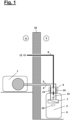
- Fig. 1 shows a schematic diagram of a split heat pump with an outdoor unit 1 and an indoor unit 2.
- the outdoor unit is designed as an air heat pump and contains the compressor, the evaporator heat exchanger and the expansion valve, and is ventilated. It is connected by refrigerant lines 3 and 4 to the indoor unit 2, which is installed in a residential building 5.
- the indoor unit 2 is encapsulated in a capsule housing 6 and can be installed in the same
- the housing can also contain a hot water generator; it can also be connected to an air conditioning system for summer operation.
- the encapsulation of the indoor unit 2 ensures that all refrigerant-carrying parts cannot come into direct contact with the air of the residential building 5.
- an air line 8 leads through a capsule housing designed as a pressure-tight adapter 9 and through a breakthrough through the outer wall 10 into the outer area 11. There, the air line 8 ends in an opening 12 protected against blockage.
- the air line 8 is open at opening 13 in the inner part 2 and is permeable within the passage through the adapter 9.
- the connections 14 and 15 of the refrigerant lines, shown here as valves, are encapsulated within the adapter 9. A possible leak would be conducted through the air line 8 to the outer area 11. In the same way, a leak 16 would pass through the opening 13 into the air line 8 and from there through the opening 12 into the outer area 11.
- Fig. 2 shows schematically the same structure as in Fig. 1 with the difference that within the capsule housing 6, a further capsule housing 17 is provided, which encloses the heat exchanger 7 and the refrigerant connections in a pressure-tight manner.
- the capsule housing 17 is connected to the air line 8 and vented as in Fig. 1 described in the outside area 11.
- several capsule housings with refrigerant-carrying installations can be provided in the capsule housing, which are then all connected to the air line 8.
- each of the capsule housings located in the capsule housing 6 can be equipped with its own adapter for connection, which is identical to the adapter 9 and contains connecting parts. This facilitates disassembly and/or repair in the event of a leak.
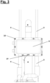
- Fig. 3 shows the closed adapter 9 according to the invention in an external view.
- the continuous refrigerant lines 3 and 4 as well as the continuous air line 8 are shown. Pressure tightness is achieved by screw connections 18 and seals.
- a safety switch 27 checks whether the adapter 9 is properly closed and prevents operation if this is not the case.
- Fig. 4 shows the closed adapter 9 according to the invention in perspective view.
- Fig. 3 In addition, the simple structure with the front 19, the back 20 and the seal 21 between the front and back is shown.
- Fig. 5 shows the transparent adapter 9 according to the invention in perspective view.
- the air line 8 is not passed through, but the permeability exists in a recess between the connection seals.
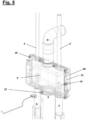
- Fig. 6 shows the adapter 9 with a capsule housing 17, in which the heat exchanger 7 is located, in an external view.
- the upper part of Fig. 6 corresponds to the Fig. 3 to 5 shown adapter 9.
- the heat exchanger 7 is surrounded by a larger capsule housing 17, which basically has the same structure as the smaller capsule housing 6 of the adapter 9, additionally with passages for the heating water flow 22 and heating water return 23, a drainage 24 as well as for a refrigerant air separator 25 and a pressure relief valve 26, which is connected to the air line 8. 6.
- Fig. 7 shows the subject of Fig. 6 perspective.
Landscapes
- Engineering & Computer Science (AREA)
- Chemical & Material Sciences (AREA)
- Combustion & Propulsion (AREA)
- Mechanical Engineering (AREA)
- General Engineering & Computer Science (AREA)
- Physics & Mathematics (AREA)
- Thermal Sciences (AREA)
- Other Air-Conditioning Systems (AREA)
Applications Claiming Priority (1)
| Application Number | Priority Date | Filing Date | Title |
|---|---|---|---|
| DE102023135487.6A DE102023135487A1 (de) | 2023-12-18 | 2023-12-18 | Gekapselter Adapter für eine Split-Wärmepumpe |
Publications (1)
| Publication Number | Publication Date |
|---|---|
| EP4575332A1 true EP4575332A1 (fr) | 2025-06-25 |
Family
ID=93923772
Family Applications (1)
| Application Number | Title | Priority Date | Filing Date |
|---|---|---|---|
| EP24219783.8A Pending EP4575332A1 (fr) | 2023-12-18 | 2024-12-13 | Adaptateur encapsulé pour pompe à chaleur divisée |
Country Status (2)
| Country | Link |
|---|---|
| EP (1) | EP4575332A1 (fr) |
| DE (1) | DE102023135487A1 (fr) |
Cited By (1)
| Publication number | Priority date | Publication date | Assignee | Title |
|---|---|---|---|---|
| DE102024119539A1 (de) * | 2024-07-10 | 2026-01-15 | Vaillant Gmbh | Hybrid-Wärmepumpensystem |
Citations (15)
| Publication number | Priority date | Publication date | Assignee | Title |
|---|---|---|---|---|
| DE102009029392A1 (de) | 2009-09-11 | 2011-03-24 | WESKA Kälteanlagen GmbH | Explosionsgeschützte Kälteanlage mit brennbarem Kältemittel |
| EP2402666A2 (fr) * | 2010-06-30 | 2012-01-04 | Fujitsu General Limited | Unité de distribution de réfrigérant pour climatiseur |
| DE102011116863A1 (de) | 2011-10-25 | 2013-04-25 | Fraunhofer-Gesellschaft zur Förderung der angewandten Forschung e.V. | Verfahren zur Sicherung einer Vorrichtung für einen thermodynamischen Kreisprozess und abgesicherte Vorrichtung für einen thermodynamischen Kreisprozess |
| WO2015032905A1 (fr) | 2013-09-05 | 2015-03-12 | Holger König | Procédé permettant d'empêcher une fuite d'un contenant et contenant pourvu d'un dispositif anti-fuite |
| DE202016103305U1 (de) | 2016-06-22 | 2016-07-07 | Futron GmbH | Explosionsgeschützte Vorrichtung zum Temperieren von Wärmeträgerfluiden |
| EP2647920B1 (fr) | 2010-12-03 | 2020-03-04 | Mitsubishi Electric Corporation | Appareil de climatisation |
| EP3358279B1 (fr) * | 2015-09-30 | 2020-06-24 | Daikin Industries, Ltd. | Ensemble de logement d'échangeur de chaleur à eau |
| DE102019001634A1 (de) | 2019-03-08 | 2020-09-10 | Stiebel Eltron Gmbh & Co. Kg | Wärmepumpe |
| EP3792572A1 (fr) | 2019-09-12 | 2021-03-17 | Vaillant GmbH | Dispositif de rinçage de sécurité pour une pompe à chaleur |
| EP3705823B1 (fr) | 2019-03-05 | 2022-02-16 | Vaillant GmbH | Dispositif pour une intervention de service en toute sécurité pour un boîtier et procédé d'ouverture du boîtier. |
| EP3598039B1 (fr) | 2017-03-15 | 2022-07-27 | Mitsubishi Electric Corporation | Dispositif de pompe à chaleur et son procédé d'installation |
| EP4194769A1 (fr) * | 2021-12-07 | 2023-06-14 | Glen Dimplex Deutschland GmbH | Installation de réfrigérant et module de réfrigérant |
| EP3839360B1 (fr) | 2019-12-20 | 2023-11-01 | Daikin Europe N.V. | Pompe à chaleur et son procédé d'installation |
| DE102022123440A1 (de) | 2022-09-14 | 2024-03-14 | Vaillant Gmbh | Serviceanschluss für ein Wärmepumpengehäuse |
| EP4467885A1 (fr) | 2023-05-26 | 2024-11-27 | Daikin Europe N.V. | Unité intérieure et pompe à chaleur |
-
2023
- 2023-12-18 DE DE102023135487.6A patent/DE102023135487A1/de active Pending
-
2024
- 2024-12-13 EP EP24219783.8A patent/EP4575332A1/fr active Pending
Patent Citations (15)
| Publication number | Priority date | Publication date | Assignee | Title |
|---|---|---|---|---|
| DE102009029392A1 (de) | 2009-09-11 | 2011-03-24 | WESKA Kälteanlagen GmbH | Explosionsgeschützte Kälteanlage mit brennbarem Kältemittel |
| EP2402666A2 (fr) * | 2010-06-30 | 2012-01-04 | Fujitsu General Limited | Unité de distribution de réfrigérant pour climatiseur |
| EP2647920B1 (fr) | 2010-12-03 | 2020-03-04 | Mitsubishi Electric Corporation | Appareil de climatisation |
| DE102011116863A1 (de) | 2011-10-25 | 2013-04-25 | Fraunhofer-Gesellschaft zur Förderung der angewandten Forschung e.V. | Verfahren zur Sicherung einer Vorrichtung für einen thermodynamischen Kreisprozess und abgesicherte Vorrichtung für einen thermodynamischen Kreisprozess |
| WO2015032905A1 (fr) | 2013-09-05 | 2015-03-12 | Holger König | Procédé permettant d'empêcher une fuite d'un contenant et contenant pourvu d'un dispositif anti-fuite |
| EP3358279B1 (fr) * | 2015-09-30 | 2020-06-24 | Daikin Industries, Ltd. | Ensemble de logement d'échangeur de chaleur à eau |
| DE202016103305U1 (de) | 2016-06-22 | 2016-07-07 | Futron GmbH | Explosionsgeschützte Vorrichtung zum Temperieren von Wärmeträgerfluiden |
| EP3598039B1 (fr) | 2017-03-15 | 2022-07-27 | Mitsubishi Electric Corporation | Dispositif de pompe à chaleur et son procédé d'installation |
| EP3705823B1 (fr) | 2019-03-05 | 2022-02-16 | Vaillant GmbH | Dispositif pour une intervention de service en toute sécurité pour un boîtier et procédé d'ouverture du boîtier. |
| DE102019001634A1 (de) | 2019-03-08 | 2020-09-10 | Stiebel Eltron Gmbh & Co. Kg | Wärmepumpe |
| EP3792572A1 (fr) | 2019-09-12 | 2021-03-17 | Vaillant GmbH | Dispositif de rinçage de sécurité pour une pompe à chaleur |
| EP3839360B1 (fr) | 2019-12-20 | 2023-11-01 | Daikin Europe N.V. | Pompe à chaleur et son procédé d'installation |
| EP4194769A1 (fr) * | 2021-12-07 | 2023-06-14 | Glen Dimplex Deutschland GmbH | Installation de réfrigérant et module de réfrigérant |
| DE102022123440A1 (de) | 2022-09-14 | 2024-03-14 | Vaillant Gmbh | Serviceanschluss für ein Wärmepumpengehäuse |
| EP4467885A1 (fr) | 2023-05-26 | 2024-11-27 | Daikin Europe N.V. | Unité intérieure et pompe à chaleur |
Cited By (1)
| Publication number | Priority date | Publication date | Assignee | Title |
|---|---|---|---|---|
| DE102024119539A1 (de) * | 2024-07-10 | 2026-01-15 | Vaillant Gmbh | Hybrid-Wärmepumpensystem |
Also Published As
| Publication number | Publication date |
|---|---|
| DE102023135487A1 (de) | 2025-06-18 |
Similar Documents
| Publication | Publication Date | Title |
|---|---|---|
| EP3792572B1 (fr) | Dispositif de rinçage de sécurité pour une pompe à chaleur | |
| EP3578895B1 (fr) | Dispositif et procédé pour le rinçage sûr et économique d'une enceinte | |
| EP3486582A1 (fr) | Détection des fuites au moyen de capacité adsorbante | |
| EP3693683B1 (fr) | Barrière de diffusion au moyen de couches de protection | |
| EP3581861B1 (fr) | Sorption du fluide | |
| EP4008979B1 (fr) | Dispositif pour effectuer en toute sécurité un cycle thermodynamique du sens anti-horaire | |
| EP3748257B1 (fr) | Dispositif pour la performance sûre d'un procédé circulaire thermodynamique à rotation à gauche au moyen d'un fluide de travail inflammable avec adsorption de fluide | |
| EP3940314B1 (fr) | Dispositif de rinçage de sécurité pour une pompe à chaleur | |
| EP3705823B1 (fr) | Dispositif pour une intervention de service en toute sécurité pour un boîtier et procédé d'ouverture du boîtier. | |
| EP3693687B1 (fr) | Refroidissement d'adsorbant | |
| EP3543629B1 (fr) | Boîtier étanche aux fuites pour un processus cyclique | |
| EP3486564B1 (fr) | DISPOSITIF POUR UNE MISE EN OEUVRE SÉCURITAIRE D'UN PROCESSUS DE RANKINE CLAUSIUS THERMODYNAMIQUE À COMMUTATION GAUCHE
BASÉ SUR UNE ADSORPTION DE FLUIDE DE TRAVAIL À REFOULEMENT DE GAZ INERTE | |
| EP4575332A1 (fr) | Adaptateur encapsulé pour pompe à chaleur divisée | |
| EP3951282A1 (fr) | Traitement actif de l'air d'évacuation d'une pompe à chaleur | |
| DE102019121496A1 (de) | Sicherheitsspülvorrichtung für eine Wärmepumpe | |
| DE102019114738A1 (de) | Fluidadsorption | |
| EP3486575B1 (fr) | Dispositif et procédé d'évacuation de sécurité du flux de travail | |
| EP3647684B1 (fr) | Zone de sécurité du condenseur | |
| EP3712531A1 (fr) | Dispositif de rinçage de sécurité pour une pompe à chaleur | |
| DE102019118977A1 (de) | Adsorberkühlung | |
| DE102024111623A1 (de) | Split-Wärmepumpe mit Modulgehäuse | |
| EP3647685B1 (fr) | Dispositif | |
| DE102019119871A1 (de) | Vorrichtung und Verfahren zur Belüftung einer Wärmepumpe | |
| DE102019108367A1 (de) | Außen aufgestellte Wärmepumpe | |
| EP3492846A1 (fr) | Récipient de sécurité pour fluide de travail |
Legal Events
| Date | Code | Title | Description |
|---|---|---|---|
| PUAI | Public reference made under article 153(3) epc to a published international application that has entered the european phase |
Free format text: ORIGINAL CODE: 0009012 |
|
| STAA | Information on the status of an ep patent application or granted ep patent |
Free format text: STATUS: THE APPLICATION HAS BEEN PUBLISHED |
|
| AK | Designated contracting states |
Kind code of ref document: A1 Designated state(s): AL AT BE BG CH CY CZ DE DK EE ES FI FR GB GR HR HU IE IS IT LI LT LU LV MC ME MK MT NL NO PL PT RO RS SE SI SK SM TR |
|
| STAA | Information on the status of an ep patent application or granted ep patent |
Free format text: STATUS: REQUEST FOR EXAMINATION WAS MADE |
|
| 17P | Request for examination filed |
Effective date: 20251218 |