EP3770624B1 - Procédés et dispositifs de prise en compte du signal de résonance magnétique lors d'un antiparasitage - Google Patents
Procédés et dispositifs de prise en compte du signal de résonance magnétique lors d'un antiparasitage Download PDFInfo
- Publication number
- EP3770624B1 EP3770624B1 EP19188305.7A EP19188305A EP3770624B1 EP 3770624 B1 EP3770624 B1 EP 3770624B1 EP 19188305 A EP19188305 A EP 19188305A EP 3770624 B1 EP3770624 B1 EP 3770624B1
- Authority
- EP
- European Patent Office
- Prior art keywords
- magnetic resonance
- interference signal
- signal
- antenna
- receiver
- Prior art date
- Legal status (The legal status is an assumption and is not a legal conclusion. Google has not performed a legal analysis and makes no representation as to the accuracy of the status listed.)
- Active
Links
Images

Classifications
-
- G—PHYSICS
- G01—MEASURING; TESTING
- G01R—MEASURING ELECTRIC VARIABLES; MEASURING MAGNETIC VARIABLES
- G01R33/00—Arrangements or instruments for measuring magnetic variables
- G01R33/20—Arrangements or instruments for measuring magnetic variables involving magnetic resonance
- G01R33/44—Arrangements or instruments for measuring magnetic variables involving magnetic resonance using nuclear magnetic resonance [NMR]
- G01R33/48—NMR imaging systems
- G01R33/54—Signal processing systems, e.g. using pulse sequences ; Generation or control of pulse sequences; Operator console
- G01R33/56—Image enhancement or correction, e.g. subtraction or averaging techniques, e.g. improvement of signal-to-noise ratio and resolution
- G01R33/565—Correction of image distortions, e.g. due to magnetic field inhomogeneities
-
- G—PHYSICS
- G01—MEASURING; TESTING
- G01R—MEASURING ELECTRIC VARIABLES; MEASURING MAGNETIC VARIABLES
- G01R33/00—Arrangements or instruments for measuring magnetic variables
- G01R33/20—Arrangements or instruments for measuring magnetic variables involving magnetic resonance
- G01R33/28—Details of apparatus provided for in groups G01R33/44 - G01R33/64
- G01R33/32—Excitation or detection systems, e.g. using radio frequency signals
- G01R33/36—Electrical details, e.g. matching or coupling of the coil to the receiver
- G01R33/3621—NMR receivers or demodulators, e.g. preamplifiers, means for frequency modulation of the MR signal using a digital down converter, means for analog to digital conversion [ADC] or for filtering or processing of the MR signal such as bandpass filtering, resampling, decimation or interpolation
-
- G—PHYSICS
- G01—MEASURING; TESTING
- G01R—MEASURING ELECTRIC VARIABLES; MEASURING MAGNETIC VARIABLES
- G01R33/00—Arrangements or instruments for measuring magnetic variables
- G01R33/20—Arrangements or instruments for measuring magnetic variables involving magnetic resonance
- G01R33/28—Details of apparatus provided for in groups G01R33/44 - G01R33/64
- G01R33/38—Systems for generation, homogenisation or stabilisation of the main or gradient magnetic field
- G01R33/385—Systems for generation, homogenisation or stabilisation of the main or gradient magnetic field using gradient magnetic field coils
- G01R33/3854—Systems for generation, homogenisation or stabilisation of the main or gradient magnetic field using gradient magnetic field coils means for active and/or passive vibration damping or acoustical noise suppression in gradient magnet coil systems
-
- G—PHYSICS
- G01—MEASURING; TESTING
- G01R—MEASURING ELECTRIC VARIABLES; MEASURING MAGNETIC VARIABLES
- G01R33/00—Arrangements or instruments for measuring magnetic variables
- G01R33/20—Arrangements or instruments for measuring magnetic variables involving magnetic resonance
- G01R33/28—Details of apparatus provided for in groups G01R33/44 - G01R33/64
- G01R33/32—Excitation or detection systems, e.g. using radio frequency signals
- G01R33/36—Electrical details, e.g. matching or coupling of the coil to the receiver
-
- G—PHYSICS
- G01—MEASURING; TESTING
- G01R—MEASURING ELECTRIC VARIABLES; MEASURING MAGNETIC VARIABLES
- G01R33/00—Arrangements or instruments for measuring magnetic variables
- G01R33/20—Arrangements or instruments for measuring magnetic variables involving magnetic resonance
- G01R33/28—Details of apparatus provided for in groups G01R33/44 - G01R33/64
- G01R33/38—Systems for generation, homogenisation or stabilisation of the main or gradient magnetic field
- G01R33/385—Systems for generation, homogenisation or stabilisation of the main or gradient magnetic field using gradient magnetic field coils
-
- G—PHYSICS
- G01—MEASURING; TESTING
- G01R—MEASURING ELECTRIC VARIABLES; MEASURING MAGNETIC VARIABLES
- G01R33/00—Arrangements or instruments for measuring magnetic variables
- G01R33/20—Arrangements or instruments for measuring magnetic variables involving magnetic resonance
- G01R33/44—Arrangements or instruments for measuring magnetic variables involving magnetic resonance using nuclear magnetic resonance [NMR]
- G01R33/48—NMR imaging systems
- G01R33/54—Signal processing systems, e.g. using pulse sequences ; Generation or control of pulse sequences; Operator console
- G01R33/543—Control of the operation of the MR system, e.g. setting of acquisition parameters prior to or during MR data acquisition, dynamic shimming, use of one or more scout images for scan plane prescription
-
- G—PHYSICS
- G01—MEASURING; TESTING
- G01R—MEASURING ELECTRIC VARIABLES; MEASURING MAGNETIC VARIABLES
- G01R33/00—Arrangements or instruments for measuring magnetic variables
- G01R33/20—Arrangements or instruments for measuring magnetic variables involving magnetic resonance
- G01R33/44—Arrangements or instruments for measuring magnetic variables involving magnetic resonance using nuclear magnetic resonance [NMR]
- G01R33/48—NMR imaging systems
- G01R33/54—Signal processing systems, e.g. using pulse sequences ; Generation or control of pulse sequences; Operator console
- G01R33/56—Image enhancement or correction, e.g. subtraction or averaging techniques, e.g. improvement of signal-to-noise ratio and resolution
- G01R33/5608—Data processing and visualization specially adapted for MR, e.g. for feature analysis and pattern recognition on the basis of measured MR data, segmentation of measured MR data, edge contour detection on the basis of measured MR data, for enhancing measured MR data in terms of signal-to-noise ratio by means of noise filtering or apodization, for enhancing measured MR data in terms of resolution by means for deblurring, windowing, zero filling, or generation of gray-scaled images, colour-coded images or images displaying vectors instead of pixels
-
- G—PHYSICS
- G01—MEASURING; TESTING
- G01R—MEASURING ELECTRIC VARIABLES; MEASURING MAGNETIC VARIABLES
- G01R33/00—Arrangements or instruments for measuring magnetic variables
- G01R33/20—Arrangements or instruments for measuring magnetic variables involving magnetic resonance
- G01R33/24—Arrangements or instruments for measuring magnetic variables involving magnetic resonance for measuring direction or magnitude of magnetic fields or magnetic flux
- G01R33/243—Spatial mapping of the polarizing magnetic field
-
- G—PHYSICS
- G01—MEASURING; TESTING
- G01R—MEASURING ELECTRIC VARIABLES; MEASURING MAGNETIC VARIABLES
- G01R33/00—Arrangements or instruments for measuring magnetic variables
- G01R33/20—Arrangements or instruments for measuring magnetic variables involving magnetic resonance
- G01R33/28—Details of apparatus provided for in groups G01R33/44 - G01R33/64
- G01R33/32—Excitation or detection systems, e.g. using radio frequency signals
- G01R33/34—Constructional details, e.g. resonators, specially adapted to MR
- G01R33/341—Constructional details, e.g. resonators, specially adapted to MR comprising surface coils
- G01R33/3415—Constructional details, e.g. resonators, specially adapted to MR comprising surface coils comprising arrays of sub-coils, i.e. phased-array coils with flexible receiver channels
-
- G—PHYSICS
- G01—MEASURING; TESTING
- G01R—MEASURING ELECTRIC VARIABLES; MEASURING MAGNETIC VARIABLES
- G01R33/00—Arrangements or instruments for measuring magnetic variables
- G01R33/20—Arrangements or instruments for measuring magnetic variables involving magnetic resonance
- G01R33/44—Arrangements or instruments for measuring magnetic variables involving magnetic resonance using nuclear magnetic resonance [NMR]
- G01R33/48—NMR imaging systems
- G01R33/4818—MR characterised by data acquisition along a specific k-space trajectory or by the temporal order of k-space coverage, e.g. centric or segmented coverage of k-space
- G01R33/4824—MR characterised by data acquisition along a specific k-space trajectory or by the temporal order of k-space coverage, e.g. centric or segmented coverage of k-space using a non-Cartesian trajectory
Definitions
- the invention relates to a method for active interference suppression in a magnetic resonance tomograph and a magnetic resonance tomograph with a receiver.
- Magnetic resonance tomographs are imaging devices which, in order to image an examination object, align nuclear spins of the examination object with a strong external magnetic field and excite them to precess around this alignment by means of an alternating magnetic field. The precession or return of the spins from this excited state to a lower-energy state in turn generates an alternating magnetic field in response, which is received by antennas.
- a spatial coding is impressed on the signals, which subsequently enables the received signal to be assigned to a volume element.
- the signal received is then evaluated and a three-dimensional imaging representation of the examination object is provided.
- local receiving antennas so-called local coils, are preferably used, which are arranged directly on the examination object to achieve a better signal-to-noise ratio.
- the receiving antennas can also be installed in a patient couch.
- Magnetic resonance tomographs require radiofrequency shielding in two ways.
- high-frequency pulses with outputs in the kilowatt range are generated, which are only partially absorbed in the patient. Radio waves leaving the patient passageway are radiated into the room and must therefore be shielded to meet emission limits.
- the magnetic resonance signals to be received for imaging are extremely weak. To here a sufficient To achieve signal-to-noise ratio (SNR), shielding from external interference signals is required.
- SNR signal-to-noise ratio
- the magnetic resonance tomograph has a first receiving antenna for receiving a magnetic resonance signal from a patient in a patient tunnel, a second receiving antenna for receiving a signal with the Larmor frequency of the magnetic resonance signal, and a receiver.
- the second receiving antenna is arranged outside or near an opening of the patient tunnel.
- the receiver is in signal communication with the first receiving antenna and the second receiving antenna and is designed to suppress an interference signal received with the second receiving antenna in a magnetic resonance signal received by the first receiving antenna.
- the document JP 2018-201599 A discloses an interference suppression device that includes a frequency estimator, a phase estimator, a periodic signal generator, an amplitude estimator, a signal replication device, and a suppression device.
- a frequency estimator the phase estimator and the amplitude estimation device
- a frequency, phase and periodic amplitude change of an interference are determined, with the generator for periodic signals and the signal replication device based on the determined frequency, phase and amplitude change an interference signal is synthesized and thus in the suppression device an interference signal in one Received signal suppressed.
- the document US 2008/0048658 A1 proposes a signal processing device for active suppression of electromagnetic interference signals from an environment.
- the system uses a noise sensor outside of an image capture volume to detect the electromagnetic noise signal in the environment and subtracts the correlated noise signal in the environment signal from the image capture signal.
- Z-It is also recommended to downscale the MR signal acquired in the imaging volume and subtract it from the noise signal, to prevent the signal of interest from being interpreted as noise.
- the object is achieved by a method according to the invention for operating the magnetic resonance tomograph according to claims 1, 2 and 3, and with a magnetic resonance tomograph according to claims 6, 7 and 8.
- the method according to the invention is provided for suppressing interference signals in a magnetic resonance recording with a magnetic resonance tomograph.
- the suppression of interference signals is not merely a passive reduction through shielding measures, but through steps and measures in the processing of the received signals.
- the magnetic resonance tomograph has a controller and a receiver.
- the receiver is designed to receive the magnetic resonance signals required for imaging from one or more antennas and to process them for a subsequent image reconstruction. This can include amplification and filtering, for example.
- the receiver is designed in particular to process magnetic resonance signals at the Larmor frequency, the Larmor frequency being predetermined by a static magnetic field B0 of the magnetic resonance tomograph and the magnetic moment or the spin of the nuclei to be detected.
- the magnetic resonance signal is received by one or more antennas, for example a local coil with antenna coils or a body coil.
- the receiver can have individual reception channels for each antenna coil or also reception channels for combined signals from a number of antennas.
- a signal which is at least predominantly generated by a resonance of excited nuclear spins of the nuclei to be examined is regarded as the magnetic resonance signal of the antennas.
- a proportion of noise or others is unavoidable Interfering signals, which are however attenuated by 12 dB, 18 dB, 24 dB, 36 dB or more compared to the signal of the nuclear spins.
- the magnetic resonance tomograph also has one or more interference signal sensors.
- An antenna or sensor is regarded as an interference signal sensor which picks up the interference signal more strongly than the magnetic resonance signal, for example by 6 dB, 12 dB, 18 dB or more above the magnetic resonance signal.
- the interference signal sensor can be an antenna which, for example, preferentially picks up the interference signal due to its position outside the patient tunnel.
- a dedicated sensor is also conceivable, such as an induction coil that picks up an interference signal from a supply line.
- the receiver receives a reference interference signal via the interference signal sensor.
- the receiver receives the magnetic resonance signal via the antenna.
- the reference interference signal can be detected at a different time, i.e. during disjunctive time segments, from the acquisition of the MR signal, so that the interference signal sensor can also be an antenna for image acquisition. Or there is a spatial separation by an interference signal sensor, which is also spatially spaced from the antenna for receiving the MR signal.
- the reference interference signal also has a small portion of the magnetic resonance signal, as already explained with regard to the interference signal sensor. It is both possible that both signals are received simultaneously, but also conceivable that the two signals are received simultaneously and separately at different times or alternately.
- the received emission of the nuclear spins is referred to as a magnetic resonance signal, especially in the case of a temporal separation, even if this is no longer used for imaging. Due to the exponential decay of the signals of the nuclear spins over time, magnetic resonance signals are also present outside the reception windows used for imaging, even if their intensity is lower.
- the receiver reduces a portion of the interference signal in the magnetic resonance signal as a function of the reference interference signal.
- the receiver can amplify the reference interference signal of the interference signal detector by a factor with an amplifier and delay it in phase with a delay element in such a way that the amount of amplitude corresponds to the component of the interference signal in the magnetic resonance signal of the antenna and has the opposite sign.
- the proportion of the interference signal in the magnetic resonance signal can be reduced, ideally almost to zero, by adding the two signals by means of a summation element, for example.
- the receiver and/or the controller determine the attenuation of the interference signal in the magnetic resonance signal and the phase shift, for example by autocorrelation of the magnetic resonance signal and reference interference signal.
- the method according to the invention therefore also provides the step of reducing the interference signal as a function of a proportion of the magnetic resonance signal in the reference interference signal received from the interference signal sensor, in other words determining or estimating an influence of the magnetic resonance signal on the reference interference signal and in the subsequent determination the parameter, such as damping and/or phase shift for interference suppression in the magnetic resonance signal.
- the parameter such as damping and/or phase shift for interference suppression in the magnetic resonance signal.
- the method according to the invention advantageously makes it possible to reduce or prevent artifacts as a result of the interference suppression.
- the method has the step of using a magnetic resonance measurement to fill a k-space with measurement data from an image acquisition. This can be done, for example, with a classic image acquisition using a gradient echo sequence, in which k-space is scanned line by line.
- a magnetic resonance signal is determined from this k-space measurement data at a respective point in time of the acquisition of the reference interference signal. Since the reference interference signal is not necessarily acquired at the same time as a magnetic resonance signal is acquired, which then corresponds to a point in k-space, it is necessary to interpolate the magnetic resonance signal from the k-space data between the measurement points while the reference interference signal is being acquired.
- Gridding is commonly used to convert measurement data from a spiral or radial scan for a simplified Fourier transform in image space to a virtual scan in rows of a Cartesian grid of k-space (see also Handbook of MRI Pulse Sequences; Bernstein, King, Zhou; Elsevier Academic Press, ISBN-13:978-0-12-092861-3, Chapter 13.2 ).
- gridding is used to determine the MR signal at the point in time when the reference interference signal is detected.
- a reference interference signal without a magnetic resonance component can be determined, for example by difference formation or an adaptive filter.
- Parameters for suppressing the interference signal in the magnetic resonance signal are then in turn determined from this filtered reference interference signal by the controller or the receiver.
- the inventive method to determine the interference signal and the magnetic resonance signal separately it is conceivable, for example, for the interference signal received by the interference signal sensor to be freed from the component of the magnetic resonance signal using, for example, adaptive filters or by subtracting the determined magnetic resonance signal component before it is combined with the magnetic resonance signal of the antennas is combined.
- it would also be conceivable to parameterize the interference suppression of the magnetic resonance signal received by the antenna itself for example by means of adaptive filters, such that a magnetic resonance signal component in the interference signal is not taken into account in the interference suppression.
- the method has the step of determining quantitative information about the object to be examined by means of an MR measurement.
- quantitative information can be taken from T1 and/or T2 maps, for example, which are determined as part of fingerprinting in preparation for image acquisition.
- a proportion of the magnetic resonance signal in the reference interference signal is determined from the quantitative information. For example, it is conceivable that due to the determined quantitative Information an MR signal of the examination subject is simulated or synthesized using Bloch equations in order to subtract the magnetic resonance signal determined in this way from the reference noise signal or to take it into account in the reduction of the noise signal in the magnetic resonance signal.
- a synthetic magnetic resonance signal previously obtained from quantitative information also advantageously allows a proportion of the magnetic resonance signal to be determined in the reference interference signal and to be taken into account in the interference suppression in order to reduce artifacts caused by the interference suppression.
- the magnetic resonance tomograph has a plurality of antennas for receiving the magnetic resonance signal.
- this is carried out as a function of the reference interference signal and a magnetic resonance signal of a second antenna.
- the signals of a second antenna and/or further antennas are also used during suppression.
- the interference signal can be inferred by correlating the signals received by the antennas.
- the phase of the interference signal between the antennas can be shifted due to the different spatial arrangement of the antennas, so that a phase shift is determined by correlating the signals from the antennas and the different phase shift is correspondingly applied to the signal from the interference signal sensor before it is used to reduce the interference signal is subtracted from the magnetic resonance signal of the respective antenna.
- the magnetic resonance signal at the interference signal sensor is in this case determined by a weighted sum over the first antenna, the second antenna and optionally further antennas, each with different phase shift estimated approximately, to then subtract it from the received signal of the Störsignalsensors.
- the inclusion of the signals of a second or further antenna when reducing the interference signal in the magnetic resonance signal of the first antenna enables a more precise assessment and thus reduced image artifacts.
- the method has a step of determining a transfer function of the magnetic resonance signal from the examination subject to the interference signal sensor. It is conceivable to use Maxwell's field equations to calculate a field strength of the magnetic resonance signal at the location of the interference signal detector. However, it would also be conceivable, as described above, to recognize an estimated MR signal at the location of the examination subject by autocorrelation in the signal of the interference signal sensor and thus to determine a transfer function.
- a transfer function Once a transfer function has been determined, it can then be assumed to be constant, in particular for image acquisition with the same examination object and the same arrangement. In the event of changes, the step of determining the transfer function could then be repeated.
- the transfer function advantageously allows a portion of the magnetic resonance signal in the signal of the interference signal sensor to be predicted more precisely using the ascertained magnetic resonance signal.
- the magnetic resonance tomograph has a field camera.
- a field camera is a device that is designed to record the magnetic field, in particular the time-varying gradient field, in the vicinity of the examination object in order to detect, for example, deviations caused by eddy currents or the examination object itself.
- the field camera records the course of the gradient field over time.
- the controller or the receiver determines the proportion of the magnetic resonance signal in the reference interference signal as a function of the time profile of the gradient field recorded by the field camera. This can be done, for example, by the gridding already explained, with the k-space positions of the measurements being corrected using the magnetic field recorded by the field camera.
- the corrected magnetic field values corresponding to the recording of the field camera are used, for example, for the Bloch equations.
- Recording the gradient fields with a field camera advantageously allows the proportion of the magnetic resonance signal in the reference interference signal to be determined more precisely, and thus better correction.
- the magnetic resonance tomograph has a plurality of antennas for receiving the magnetic resonance signal.
- This can be, for example, multiple antenna coils of a local coil matrix, multiple separate local coils that are connected to different Positions are arranged or one or more local coils and the body coil.
- At least the magnetic resonance signal picked up by a second antenna is also used for interference suppression.
- the interference is suppressed as a function of the reference interference signal and a magnetic resonance signal from the second antenna.
- An interference signal that was picked up by the interference signal sensor is therefore also shifted by a certain phase amount when it is received by the first and the second antenna, which corresponds to a distance difference divided by the propagation speed.
- the magnetic resonance signal at the interference signal sensor can be approximately estimated by a weighted sum over the first antenna, the second antenna and possibly other antennas, each with a different phase shift, in order to then subtract it from the received signal of the interference signal sensor.
- the inclusion of the signals of a second or further antennas when reducing the interference signal in the magnetic resonance signal of the first antenna enables a more precise estimation and thus reduced image artifacts.
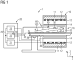
- FIG. 1 shows a schematic representation of an embodiment of a magnetic resonance tomograph 1 with a local coil 50 according to the invention.
- the magnet unit 10 has a field magnet 11 that generates a static magnetic field B0 for aligning nuclear spins of samples or of the patient 100 in a recording area.
- the recording area is characterized by an extremely homogeneous static magnetic field B0, with the homogeneity particularly affecting the magnetic field strength and its magnitude.
- the recording area is almost spherical and is arranged in a patient tunnel 16 which extends through the magnet unit 10 in a longitudinal direction 2 .
- a patient couch 30 can be moved in the patient tunnel 16 by the traversing unit 36 .
- the field magnet 11 is usually a superconducting magnet that can provide magnetic fields with a magnetic flux density of up to 3T, and even more in the case of the latest devices. For lesser Field strengths, however, permanent magnets or electromagnets with normally conducting coils can also be used.
- the magnet unit 10 has gradient coils 12, which are designed to superimpose variable magnetic fields in three spatial directions on the magnetic field B0 for spatial differentiation of the recorded imaging regions in the examination volume.
- the gradient coils 12 are usually coils made from normally conducting wires, which can generate mutually orthogonal fields in the examination volume.
- the magnet unit 10 also has a body coil 14 which is designed to emit a high-frequency signal supplied via a signal line into the examination volume and to receive resonance signals emitted by the patient 100 and emit them via a signal line.
- a control unit 20 supplies the magnet unit 10 with the various signals for the gradient coils 12 and the body coil 14 and evaluates the received signals.
- control unit 20 has a gradient control 21, which is designed to supply the gradient coils 12 with variable currents via supply lines, which provide the desired gradient fields in the examination volume in a time-coordinated manner.
- control unit 20 has a high-frequency unit 22 which is designed to generate a high-frequency pulse with a predetermined time profile, amplitude and spectral power distribution for exciting a magnetic resonance of the nuclear spins in the patient 100 .
- Pulse powers in the kilowatt range can be achieved.
- the excitation pulses can be radiated into the patient 100 via the body coil 14 or also via a local transmitting antenna.
- a controller 23 communicates with the gradient controller 21 and the radio-frequency unit 22 via a signal bus 25.
- a local coil 50 is arranged on the patient 100 as a first antenna and is connected to the radio-frequency unit 22 and its receiver via a connecting line 33 .
- the body coil 14 is a first antenna within the meaning of the invention.
- At one edge of the opening of the patient tunnel 16 are four noise sensors 60 located at the corners of a square inscribed in the circular opening such that the corners come to rest on the edge of the opening.
- the four interference signal sensors 60 are in signal connection with the receiver 70 of the high-frequency unit 22. Due to the plurality of interference signal sensors 60, it is conceivable that these do not all have an all-round reception characteristic, but are, for example, dipoles and, due to the different alignment, form an all-round add characteristics. However, it would also be conceivable, for example, to provide a crossed dipole as the only second antenna with an all-round characteristic.
- an interference signal sensor 60 may be arranged in the patient bed 30 as an alternative or in addition.
- the patient tunnel preferably has a radius R for which the following applies: R ⁇ lambda L * 1,841 / 2 * pi
- lambda L indicates the wavelength of a radio wave in air at the Larmor frequency of the magnetic resonance tomograph 1 . If the radius R is smaller than the right-hand term, the radio wave propagates in the patient tunnel 16 with exponential attenuation and the interference signal is strongly attenuated in the center in the examination area FoV. Lambda L is also called Cut-off wavelength of a round waveguide called, the associated frequency as cut-off frequency.
- the interference signal sensor 60 or the interference signal sensors 60 in the vicinity of the opening or in the patient couch 30 advantageously pick up the interference signal forwarded by the patient 100 into the FoV and thereby make the compensation in the receiver 70 particularly effective.
- the patient 100 also conducts a magnetic resonance signal from the patient tunnel 16 to the interference signal sensor(s) 60 in the opposite direction For example, if the magnetic resonance signal is subtracted, this leads to falsifications of the magnetic resonance signal and to image artifacts due to the reference to the imaging magnetic resonance signal.
- the controller 23 and/or the receiver 70 of the magnetic resonance tomograph according to the invention are therefore designed to reduce the interference signal as a function of a proportion of the magnetic resonance signal in the reference interference signal received from the interference signal sensor 60 .
- the receiver 70 and/or the controller 23 carry out the in 2 illustrated method according to the invention. It is conceivable that the method is executed under program control by a processor, preferably a signal processor. However, it is also conceivable to implement the invention using logic in an FPGA or ASIC.
- the receiver 70 receives a reference interference signal via the interference signal sensor 60.
- the reference interference signal also has a component of a magnetic resonance signal that is emitted by the patient 100, even if no magnetic resonance signal is recorded via the local coil 50 or the body coil at the same time because due to the exponential drop in the magnetic resonance signal, this is weakened for a longer period of time.
- the magnetic resonance tomograph 1 receives a magnetic resonance signal from the patient 100 with the receiver 70 via an antenna, for example the local coil 50, which can also be designed as a local coil matrix with several antenna coils, or the body coil 14.
- Step S10 and step S20 do not necessarily take place simultaneously, but can also take place sequentially.
- the received magnetic resonance signal is further used for imaging by the controller 23 or a separate unit for image reconstruction and is finally output on a screen, for example.
- the receiver 70 reduces a portion of the interference signal in the magnetic resonance signal as a function of the reference interference signal. This can be done, for example, by adding the signal received from the interference signal sensor 60 to the signal from the local coil 50 with a predetermined weighting and phase shift, such that the components of the interference signal in the signal from the local coil 50 cancel out with the weighted signal .
- the phase shift and weighting can be determined, for example, by autocorrelation of the signals from the interference signal and the signal from the local coil 50 .
- step S30 it is also taken into account that the signal from the interference signal sensor 60 always a portion of a magnetic resonance signal is also contained, at least during an image acquisition with a patient 100.
- the method according to the invention therefore provides for step S30 to be carried out as a function of a portion of the magnetic resonance signal in the reference interference signal received from the interference signal sensor 60.
- k-space is filled with measurement data from an image acquisition, such as a gradient echo sequence, by means of a magnetic resonance measurement S31.
- the magnetic resonance measurement can be carried out as part of a sequence or as a preparatory measurement. In the simplest case, this can be a Cartesian grid in k-space, the nodes of which are filled with MR signals in rows and columns by suitable sequences.
- other scanning schemes along radial or spiral trajectories are also conceivable.
- the MR signal can then be interpolated at any point in time by interpolation on these k-space points.
- Appropriate methods were developed, for example in order to determine the measured values for a Cartesian coordinate system (also referred to as "gridding") in the case of a spiral trajectory and then to use a simpler back-transformation into the image space. Such methods are for example in the " Handbook of MRI Pulse Sequences"; Bernstein, King, Zhou; Elsevier Academic Press, ISBN-13:978-0-12-092861-3, Chapter 13.2 described.
- a magnetic resonance signal can be determined at least approximately, which is emitted by the patient 100 while the reference interference signal is recorded with the interference signal sensor 60 in a step S10.
- a magnetic resonance measurement S33 For example, this could be a be the spin density of the nuclear spins per volume element.
- a proportion of the magnetic resonance signal in the reference interference signal received in step S10 is determined from this quantitative information.
- the quantitative information can be used to determine a size of the portion of the magnetic resonance signal received during step S10, for example by a Bloch simulation from this spin density and a transfer function subsequently applied thereto.
- Such a transfer function can be determined in a step S35. It is conceivable, for example, for the transfer function to be simulated using Maxwell's field equations if the reception properties of the interference signal sensor 60, its arrangement relative to the examination object and the properties of the examination object are known.
- the transfer function by measurement in a step S35.
- the receiver 70 With a known magnetic resonance signal at the location of the examination object, it would be conceivable for the receiver 70 to detect the magnetic resonance signal by means of autocorrelation in the received signal of the interference signal sensor 60 and in this way to determine the transfer function with its essential parameters, in particular attenuation and phase shift.
- Step S35 can also include a combination of the methods described, so that periodic interference signals, for example, do not interfere with the method.
- Step S35 can also be executed at different points in time.
- the transfer function can be determined once for one type of magnetic resonance tomograph 1 .
- a proportion of the magnetic resonance signal to be expected in the signal of the interference signal sensor 60 can then be determined at any point in time from the determined magnetic resonance signal and the transfer function. If this determined component is then added to the signal of the interference signal sensor, for example with the opposite sign, i.e. with a phase shift of 180 degrees, the magnetic resonance signal component ideally cancels out and a pure interference signal is obtained. It is also conceivable, however, for the determined magnetic resonance signal component to be taken into account or suppressed by appropriate filter measures in the receiver 70 in the subsequent signal path in the analog or digital signal processing. This can be achieved, for example, by means of adaptive filters.
- the magnetic resonance signal can deviate from an ideal magnetic resonance signal due to undesired side effects, for example due to variations in the gradient fields due to eddy currents.
- a conceivable embodiment therefore provides for the magnetic resonance tomograph 1 to have a field camera 65 with which the magnetic field, consisting of the static component B0 and the gradient fields, is measured, preferably during step S10 and/or S20.
- a field camera 65 can, for example, transmit several samples with a material that is sensitive to magnetic resonance excitation via the patient tunnel distributed, the magnetic resonance signal of which is recorded and thus allows a precise determination of the magnetic fields at the location of the field samples.
- the field strength between the samples can also be determined from this by interpolation. It would also be conceivable to determine the magnetic field using magnetic field sensors such as Hall sensors. With the determined field strength, for example, the Bloch simulation of the magnetic resonance signals in the receiver 70 or the controller 23 can then be carried out more precisely and in this way the proportion of the magnetic resonance signal in the signal from the interference signal sensor 60 can then also be
- the magnetic resonance tomograph has a plurality of antennas for receiving the magnetic resonance signal.
- the plurality of antennas preferably local coils 50 or antenna coils of a local coil matrix, makes it possible to evaluate different mixtures of the same interference signal with a magnetic resonance signal due to the different relative positions to each other and to the patient 100 or the examination object, so that on the one hand in the signals of the Antenna better distinguishes the interference signal and can be filtered out and vice versa in the other direction in the signal of the interference signal sensor, the magnetic resonance signal component can be detected and filtered.
- the interference signal is approximately the same because of the small distance from one another in comparison to the interference signal source outside the patient tunnel 16, while the magnetic resonance signals for different volumes of the patient 100 can be distinguished.
- simulating the magnetic resonance component it can then be modeled more precisely for the different origin locations and then better suppressed or compensated for.
Landscapes
- Physics & Mathematics (AREA)
- Condensed Matter Physics & Semiconductors (AREA)
- General Physics & Mathematics (AREA)
- Engineering & Computer Science (AREA)
- Health & Medical Sciences (AREA)
- High Energy & Nuclear Physics (AREA)
- Signal Processing (AREA)
- Nuclear Medicine, Radiotherapy & Molecular Imaging (AREA)
- General Health & Medical Sciences (AREA)
- Radiology & Medical Imaging (AREA)
- Artificial Intelligence (AREA)
- Computer Vision & Pattern Recognition (AREA)
- Magnetic Resonance Imaging Apparatus (AREA)
- Life Sciences & Earth Sciences (AREA)
- Biophysics (AREA)
- Pathology (AREA)
- Biomedical Technology (AREA)
- Heart & Thoracic Surgery (AREA)
- Medical Informatics (AREA)
- Molecular Biology (AREA)
- Surgery (AREA)
- Animal Behavior & Ethology (AREA)
- Public Health (AREA)
- Veterinary Medicine (AREA)
Claims (10)
- Procédé de suppression de signaux parasites, lors d'un enregistrement par résonnance magnétique par un tomodensitomètre (1) de résonnance magnétique, dans lequel le tomodensitomètre (1) de résonnance magnétique a une commande (23), un récepteur (70), une antenne et un capteur (60) de signal parasite, dans lequel le procédé a les stades :(S10) réception d'un signal parasite de référence par le récepteur (70), par l'intermédiaire du capteur (60) de signal parasite ;(S20) réception par le récepteur (70) par l'intermédiaire de l'antenne d'un signal de résonnance magnétique d'un objet à examiner ;(S30) réduction d'une proportion du signal parasite, dans le signal de résonnance magnétique, par le récepteur (70) en fonction du signal parasite de référence,dans lequel la réduction du signal parasite s'effectue en fonction d'une proportion du signal de résonnance magnétique dans le signal parasite de référence reçu par le capteur (60) de signal parasite,caractérisé en ce quele procédé a en outre les stades,(S31) au moyen d'une mesure RM, remplissage d'un espace k par des données de mesure d'une prise d'image, et(S32) interpolation d'une proportion du signal de résonnance magnétique dans le signal parasite de référence, à l'aide d'un gridding sur les données de mesure dans l'espace k.
- Procédé de suppression de signaux parasites, lors d'un enregistrement par résonnance magnétique par un tomodensitomètre (1) de résonnance magnétique, dans lequel le tomodensitomètre (1) de résonnance magnétique a une commande (23), un récepteur (70), une antenne et un capteur (60) de signal parasite, dans lequel le procédé a les stades :(S10) réception d'un signal parasite de référence par le récepteur (70), par l'intermédiaire du capteur (60) de signal parasite ;(S20) réception d'un signal de résonnance magnétique d'un objet à examiner par le récepteur (70), par l'intermédiaire de l'antenne ;(S30) réduction d'une proportion du signal parasite, dans le signal de résonnance magnétique, par le récepteur (70) en fonction du signal parasite de référence,dans lequel la réduction du signal parasite s'effectue, en fonction d'une proportion du signal de résonnance magnétique dans le signal parasite de référence reçu par le capteur (60) de signal parasite,caractérisé en ce quele procédé a en outre les stades,(S33) détermination, au moyen d'une mesure de résonnance magnétique, d'informations quantitatives sur l'objet à examiner, et(S34) définition d'une proportion du signal de résonnance magnétique dans le signal parasite de référence, au moyen d'une simulation du signal de résonnance magnétique avec les informations quantitatives.
- Procédé de suppression de signaux parasites, lors d'un enregistrement par résonnance magnétique par un tomodensitomètre (1) de résonnance magnétique, dans lequel le tomodensitomètre (1) de résonnance magnétique a une commande (23), un récepteur (70), une antenne et un capteur (60) de signal parasite, dans lequel le procédé a les stades :(S10) réception d'un signal parasite de référence par le récepteur (70), par l'intermédiaire du capteur (60) de signal parasite ;(S20) réception d'un signal de résonnance magnétique d'un objet à examiner par le récepteur (70) par l'intermédiaire de l'antenne ;(S30) réduction d'une proportion du signal parasite, dans le signal de résonnance magnétique par le récepteur (70) en fonction du signal parasite de référence,dans lequel la réduction du signal parasite s'effectue en fonction d'une proportion du signal de résonnance magnétique dans le signal parasite de référence reçu par le capteur (60) de signal parasite,caractérisé en ce que le tomodensitomètre (1) de résonnance magnétique a une pluralité d'antennes de réception du signal de résonnance magnétique,dans lequel, dans le stade (S30) de la réduction d'une proportion du signal parasite dans le signal de résonnance magnétique d'une première antenne par le récepteur (70), cela au lieu en fonction du signal parasite de référence et d'un signal de résonnance magnétique d'une deuxième antenne,dans lequel un signal de résonnance magnétique, qui est détecté respectivement par la première antenne et la deuxième antenne,intervient avec un retard de phase correspondant, de manière à ce que le signal de résonnance magnétique au capteur (60) du signal parasite soit estimé approximativement par une somme pondérée, par l'intermédiaire de la première antenne et de la deuxième antenne,avec un décalage de phase différent respectivement, afin de le déduire alors du signal reçu du capteur (60) du signal parasite.
- Procédé suivant la revendication 1 ou 2, dans lequel le procédé a un stade (S35) de détermination d'une fonction de transfert du signal de résonnance magnétique de l'objet à examiner au capteur (60) de signal parasite.
- Procédé suivant l'une des revendications 1 à 4, dans lequel le tomodensitomètre (1) de résonnance magnétique a une caméra (65) de champ et le procédé comprend en outre le stade d'enregistrement, pendant la réception du signal (S20) de résonnance magnétique, de la courbe en fonction du temps d'un champ de gradient, au moyen de la caméra (65) de champ, dans lequel on détermine la proportion du signal de résonnance magnétique dans le signal parasite de référence en fonction de la courbe temporelle du champ de gradients enregistrée par la caméra (65) de champ.
- Tomodensitomètre à résonnance magnétique, comprenant une commande (23), un récepteur (70) et un capteur (60) de signal parasite, dans lequel le tomodensitomètre (1) à résonnance magnétique est conçupour recevoir un signal parasite de référence par le récepteur (70), par l'intermédiaire du capteur (60) de signal parasite ;pour recevoir un signal de résonnance magnétique d'un objet à examiner par le récepteur (70), par l'intermédiaire de l'antenne ;pour réduire, par le récepteur (70), une proportion du signal parasite dans le signal de résonnance magnétique, en fonction du signal parasite de référence, dans lequel la réduction du signal parasite en fonction d'une proportion du signal de résonnance magnétique, a lieu dans le signal parasite de référence reçu par le capteur (60) de signal parasite,caractérisé en ce quela commande (23) est conçue en outrepour remplir, au moyen d'une mesure RM, un espace k de données de mesure d'une prise d'image, etpour interpoler une proportion du signal de résonnance magnétique dans le signal parasite de référence, à l'aide d'un gridding sur les données de mesure dans l'espace k.
- Tomodensitomètre à résonnance magnétique, comprenant une commande (23), un récepteur (70) et un capteur (60) de signal parasite, dans lequel le tomodensitomètre (1) de résonnance magnétique est conçupour recevoir un signal parasite de référence, par le récepteur (70) par l'intermédiaire du capteur (60) de signal parasite ;pour recevoir un signal de résonnance magnétique d'un objet à examiner par le récepteur (70) par l'intermédiaire de l'antenne ;pour réduire, par le récepteur (70), une proportion du signal parasite dans le signal de résonnance magnétique, en fonction du signal parasite de référence, dans lequel la réduction du signal parasite, en fonction d'une proportion du signal de résonnance magnétique, a lieu dans le signal parasite de référence reçu par le capteur (60) de signal parasite,caractérisé en ce quela commande (23) est conçue en outrepour déterminer, au moyen d'une mesure de résonnance magnétique, des informations quantitatives sur l'objet à examiner, etpour définir une proportion du signal de résonnance magnétique dans le signal parasite de référence, au moyen d'une simulation du signal de résonnance magnétique par les informations quantitatives.
- Tomodensitomètre à résonnance magnétique, comprenant une commande (23), un récepteur (70) et un capteur (60) de signal parasite, dans lequel le tomodensitomètre (1) de résonnance magnétique est conçupour recevoir un signal parasite de référence par le récepteur (70), par l'intermédiaire du capteur (60) de signal parasite ;pour recevoir un signal de résonnance magnétique d'un objet à examiner par le récepteur (70) par l'intermédiaire de l'antenne ; pour réduire, par le récepteur (70), une proportion du signal parasite dans le signal de résonnance magnétique, en fonction du signal parasite de référence, dans lequel la réduction du signal parasite, en fonction d'une proportion du signal de résonnance magnétique, a lieu dans le signal parasite de référence reçu par le capteur (60) de signal parasite,caractérisé en ce quele tomodensitomètre de résonnance magnétique a une pluralité d'antennes de réception du signal de résonnance magnétique,la commande (23) est conçue en outrelors de la réduction d'une proportion du signal parasite dans le signal de résonnance magnétique d'une première antenne par le récepteur (70), cela a lieu en fonction du signal parasite de référence et d'un signal de résonnance magnétique d'une deuxième antenne,dans lequel un signal de résonnance magnétique, que l'on détecte respectivement par la première antenne et la deuxième antenne, intervient avec un retard de phase correspondant, dans lequel la commande (23) est conçue pour estimer approximativement le signal de résonnance magnétique au capteur (60) de signal parasite par une somme pondérée, par l'intermédiaire de la première antenne et de la deuxième antenne, ayant respectivement un déphasage différent, pour le déduire alors du signal reçu du capteur (60) de signal parasite.
- Produit de programme d'ordinateur, qui peut être chargé directement dans un processeur d'une commande (23) programmable d'un tomodensitomètre (1) de résonnance magnétique, suivant le préambule de l'une des revendications 6 à 8, comprenant des moyens de code de programme pour effectuer tous les stades d'un procédé suivant l'une des revendications 1 à 5, lorsque le produit de programme est réalisé sur la commande (23).
- Support de mémoire, déchiffrable par ordinateur, sur laquelle sont mises en mémoire des informations de commande déchiffrables électroniquement, qui sont conformées de manière à ce qu'elles effectuent, lors de l'utilisation du support de mémoire ou d'une commande (23) d'un tomodensitomètre (1) de résonnance magnétique, suivant le préambule de l'une des revendications 6 à 8, le procédé suivant l'une des revendications 1 à 5.
Priority Applications (3)
| Application Number | Priority Date | Filing Date | Title |
|---|---|---|---|
| EP19188305.7A EP3770624B1 (fr) | 2019-07-25 | 2019-07-25 | Procédés et dispositifs de prise en compte du signal de résonance magnétique lors d'un antiparasitage |
| CN202010709205.2A CN112305478B (zh) | 2019-07-25 | 2020-07-22 | 用于在噪声抑制中考虑磁共振信号的方法和设备 |
| US16/938,901 US11275135B2 (en) | 2019-07-25 | 2020-07-24 | Method and device for taking account of the magnetic resonance signal during interference suppression |
Applications Claiming Priority (1)
| Application Number | Priority Date | Filing Date | Title |
|---|---|---|---|
| EP19188305.7A EP3770624B1 (fr) | 2019-07-25 | 2019-07-25 | Procédés et dispositifs de prise en compte du signal de résonance magnétique lors d'un antiparasitage |
Publications (2)
| Publication Number | Publication Date |
|---|---|
| EP3770624A1 EP3770624A1 (fr) | 2021-01-27 |
| EP3770624B1 true EP3770624B1 (fr) | 2023-03-22 |
Family
ID=67438867
Family Applications (1)
| Application Number | Title | Priority Date | Filing Date |
|---|---|---|---|
| EP19188305.7A Active EP3770624B1 (fr) | 2019-07-25 | 2019-07-25 | Procédés et dispositifs de prise en compte du signal de résonance magnétique lors d'un antiparasitage |
Country Status (3)
| Country | Link |
|---|---|
| US (1) | US11275135B2 (fr) |
| EP (1) | EP3770624B1 (fr) |
| CN (1) | CN112305478B (fr) |
Families Citing this family (11)
| Publication number | Priority date | Publication date | Assignee | Title |
|---|---|---|---|---|
| US11940513B2 (en) * | 2020-09-16 | 2024-03-26 | Siemens Healthineers Ag | Method and apparatus for suppressing interference emissions in magnetic resonance systems |
| DE102020213938A1 (de) * | 2020-11-05 | 2022-05-05 | Siemens Healthcare Gmbh | Verfahren und Vorrichtung zur Störunterdrückung für MR-Ganzkörperantennen |
| US11860252B2 (en) * | 2021-03-09 | 2024-01-02 | Siemens Healthcare Gmbh | MR system with partial shielding cabin and method for operation |
| EP4063890B1 (fr) | 2021-03-23 | 2024-07-03 | Siemens Healthineers AG | Détection d'interférences rf dans un système de tomographie par résonance magnétique |
| CN113203969B (zh) * | 2021-04-29 | 2022-08-16 | 杭州微影医疗科技有限公司 | 干扰消除方法、介质及设备 |
| CN113176528B (zh) * | 2021-04-29 | 2025-03-18 | 杭州微影医疗科技有限公司 | 干扰消除方法、介质及设备 |
| CN113552518A (zh) * | 2021-08-16 | 2021-10-26 | 宁波穿山甲机电有限公司 | 一种磁共振成像系统的主动射频屏蔽系统 |
| CN113960505B (zh) * | 2021-10-28 | 2022-08-09 | 中国地质大学(武汉) | 一种多传感器协同测量的互干扰抑制方法及存储介质 |
| WO2023232000A1 (fr) * | 2022-05-30 | 2023-12-07 | Shanghai United Imaging Healthcare Co., Ltd. | Systèmes et procédés de collecte et de traitement de signal d'interférence |
| EP4369017B1 (fr) * | 2022-11-11 | 2025-07-02 | Siemens Healthineers AG | Appareil d'imagerie par résonance magnétique et procédé de réduction de perturbations d'image par des champs magnétiques basse fréquence |
| DE102023202435A1 (de) * | 2023-03-20 | 2024-09-26 | Siemens Healthineers Ag | Magnetresonanzvorrichtung mit einer freilaufenden Empfangskette und Verfahren zum Betrieb |
Family Cites Families (12)
| Publication number | Priority date | Publication date | Assignee | Title |
|---|---|---|---|---|
| DE4024164A1 (de) * | 1989-08-11 | 1991-02-14 | Siemens Ag | Verfahren zur verbesserung des signal-rausch-verhaeltnisses bei einem kernspin-tomographiegeraet |
| US6788063B1 (en) * | 2003-02-26 | 2004-09-07 | Ge Medical Systems Technology Company, Llc | Method and system for improving transient noise detection |
| US20080048658A1 (en) * | 2006-08-24 | 2008-02-28 | Stephen Gerard Hushek | Automatic noise cancellation for unshielded mr systems |
| DE102009015885B4 (de) * | 2009-04-01 | 2011-06-16 | Siemens Aktiengesellschaft | Verfahren zur Detektion fehlerhafter MR-Daten und Magnetresonanzanlage |
| WO2011033422A1 (fr) * | 2009-09-17 | 2011-03-24 | Koninklijke Philips Electronics N.V. | Système d'imagerie par résonance magnétique comprenant des capteurs physiologiques |
| DE102014204665B4 (de) * | 2014-03-13 | 2019-01-24 | Siemens Healthcare Gmbh | Geräuschoptimierung einer Magnetresonanzanlage |
| US10317502B2 (en) * | 2014-03-31 | 2019-06-11 | Koninklijke Philips N.V. | Magnetic resonance imaging with RF noise detection coils |
| DE102014212943B4 (de) * | 2014-07-03 | 2016-11-24 | Siemens Healthcare Gmbh | Magnetresonanz-Bildgebung unter Berücksichtigung von unterschiedlichen Frequenzkodiermustern |
| US9817093B2 (en) * | 2014-09-05 | 2017-11-14 | Hyperfine Research, Inc. | Low field magnetic resonance imaging methods and apparatus |
| EP3388855B1 (fr) * | 2017-04-12 | 2024-08-28 | Siemens Healthineers AG | Dispositif et procédé de récupération de la référence temporelle dans des chaînes de réception à rm libres |
| JP6922429B2 (ja) * | 2017-05-30 | 2021-08-18 | 富士通株式会社 | ノイズ抑圧装置、測定システム、ノイズ抑圧方法およびプログラム |
| EP3467531A1 (fr) * | 2017-10-05 | 2019-04-10 | Siemens Healthcare GmbH | Appareil d'imagerie par résonance magnétique pourvu de dispositif d'antiparasitage actif et procédé d'antiparasitage dans un appareil d'imagerie par résonance magnétique |
-
2019
- 2019-07-25 EP EP19188305.7A patent/EP3770624B1/fr active Active
-
2020
- 2020-07-22 CN CN202010709205.2A patent/CN112305478B/zh active Active
- 2020-07-24 US US16/938,901 patent/US11275135B2/en active Active
Also Published As
| Publication number | Publication date |
|---|---|
| CN112305478B (zh) | 2025-02-28 |
| CN112305478A (zh) | 2021-02-02 |
| US20210025954A1 (en) | 2021-01-28 |
| US11275135B2 (en) | 2022-03-15 |
| EP3770624A1 (fr) | 2021-01-27 |
Similar Documents
| Publication | Publication Date | Title |
|---|---|---|
| EP3770624B1 (fr) | Procédés et dispositifs de prise en compte du signal de résonance magnétique lors d'un antiparasitage | |
| EP4194875B1 (fr) | Tomographe à résonance magnétique à suppression active des parasites et procédé d'élimination des parasites dans un tomographe à résonance magnétique | |
| DE102015203385B4 (de) | Verfahren zur Erzeugung einer Bewegungsinformation zu einem zumindest teilweise bewegten Untersuchungsbereich sowie Magnetresonanzanlage und Hybrid-Bildgebungsmodalität | |
| DE102009014498B4 (de) | Verfahren, Magnetresonanzgerät und Computerprogramm zur Erstellung von Bildern mittels paralleler Akquisitionstechnik | |
| DE102009014461B4 (de) | Verfahren, Magnetresonanzgerät und Computerprogramm zur Erstellung von Bildern mittels paralleler Akquistionstechnik | |
| EP0695947B1 (fr) | Procédé de résonance magnétique pour déterminer la distribution de la magnétisation nucléaire avec un dispositif de bobine de surface | |
| DE102011083898B4 (de) | Erfassen von Magnetresonanzdaten am Rande des Gesichtsfelds einer Magnetresonanzanlage | |
| DE19804823B4 (de) | Korrektur von Artefakten, die durch Maxwell-Terme in Magnetresonanz-Echo-Planar-Bildern verursacht werden | |
| DE68926824T2 (de) | Apparat und Verfahren zur Bilderzeugung mittels magnetischer Resonanz | |
| CH693862A5 (de) | Verfahren zum Bestimmen der Inhomogenitaten eines Magnetfelds. | |
| EP3709040B1 (fr) | Procédé de fonctionnement d'une caméra à champ magnétique | |
| DE102011088828B4 (de) | Erstellung eines MR-Bildes eines Untersuchungsobjekts unter Verwendung einer für ein Empfangsspulenelement erstellten Maske | |
| DE102020202830A1 (de) | Magnetresonanztomograph und Verfahren zum Betrieb mit dynamischer B0-Kompensation | |
| DE102010043956B4 (de) | Erfassung von MR-Daten in einem vorbestimmten dreidimensionalen Volumenabschnitt unter Vermeidung von Einfaltungs- und Bandartefakten | |
| DE102015221888A1 (de) | Gleichzeitige MRT-Mehrschichtmessung | |
| DE102013220301B4 (de) | Ermittlung einer Ansteuersequenz für ein Magnetresonanzbildgebungssystem unter Verwendung eines Ausführbarkeitskriteriums | |
| EP3001212A1 (fr) | Procede et installation de resonance magnetique destines a la reconstruction d'une image mr en tenant compte du deplacement chimique | |
| DE19652060A1 (de) | Verbessertes Verfahren zur Magnet-Feldfeinkorrektion | |
| DE102016207641A1 (de) | Parallele Magnetresonanz-Akquisitionstechnik | |
| DE19814677A1 (de) | Korrektur einer durch Maxwell-Terme verursachten Verschlechterung eines Axial-Bild-Signals | |
| DE102014213413A1 (de) | Dynamische Felderfassung in einem MRT | |
| DE10114318A1 (de) | Kernspinresonanzbildartefaktkorrektur unter Verwendung von Navigatorechoinformationen | |
| EP3333584B1 (fr) | Optimisation de la détection simultanée de données rm dans des plusieurs éléments de volume ou des tranches | |
| DE10003712C2 (de) | Verfahren zur Selektion einer Lokalantenne | |
| DE102010013681B4 (de) | Korrektur sich verändernder lokaler Sendephasen bei parallelem Senden |
Legal Events
| Date | Code | Title | Description |
|---|---|---|---|
| PUAI | Public reference made under article 153(3) epc to a published international application that has entered the european phase |
Free format text: ORIGINAL CODE: 0009012 |
|
| STAA | Information on the status of an ep patent application or granted ep patent |
Free format text: STATUS: THE APPLICATION HAS BEEN PUBLISHED |
|
| AK | Designated contracting states |
Kind code of ref document: A1 Designated state(s): AL AT BE BG CH CY CZ DE DK EE ES FI FR GB GR HR HU IE IS IT LI LT LU LV MC MK MT NL NO PL PT RO RS SE SI SK SM TR |
|
| AX | Request for extension of the european patent |
Extension state: BA ME |
|
| STAA | Information on the status of an ep patent application or granted ep patent |
Free format text: STATUS: REQUEST FOR EXAMINATION WAS MADE |
|
| 17P | Request for examination filed |
Effective date: 20210719 |
|
| RBV | Designated contracting states (corrected) |
Designated state(s): AL AT BE BG CH CY CZ DE DK EE ES FI FR GB GR HR HU IE IS IT LI LT LU LV MC MK MT NL NO PL PT RO RS SE SI SK SM TR |
|
| STAA | Information on the status of an ep patent application or granted ep patent |
Free format text: STATUS: EXAMINATION IS IN PROGRESS |
|
| 17Q | First examination report despatched |
Effective date: 20220316 |
|
| GRAP | Despatch of communication of intention to grant a patent |
Free format text: ORIGINAL CODE: EPIDOSNIGR1 |
|
| STAA | Information on the status of an ep patent application or granted ep patent |
Free format text: STATUS: GRANT OF PATENT IS INTENDED |
|
| RIC1 | Information provided on ipc code assigned before grant |
Ipc: G01R 33/3415 20060101ALN20221102BHEP Ipc: G01R 33/24 20060101ALN20221102BHEP Ipc: G01R 33/48 20060101ALN20221102BHEP Ipc: G01R 33/565 20060101ALI20221102BHEP Ipc: G01R 33/36 20060101AFI20221102BHEP |
|
| RIC1 | Information provided on ipc code assigned before grant |
Ipc: G01R 33/3415 20060101ALN20221110BHEP Ipc: G01R 33/24 20060101ALN20221110BHEP Ipc: G01R 33/48 20060101ALN20221110BHEP Ipc: G01R 33/565 20060101ALI20221110BHEP Ipc: G01R 33/36 20060101AFI20221110BHEP |
|
| INTG | Intention to grant announced |
Effective date: 20221130 |
|
| GRAS | Grant fee paid |
Free format text: ORIGINAL CODE: EPIDOSNIGR3 |
|
| GRAA | (expected) grant |
Free format text: ORIGINAL CODE: 0009210 |
|
| STAA | Information on the status of an ep patent application or granted ep patent |
Free format text: STATUS: THE PATENT HAS BEEN GRANTED |
|
| AK | Designated contracting states |
Kind code of ref document: B1 Designated state(s): AL AT BE BG CH CY CZ DE DK EE ES FI FR GB GR HR HU IE IS IT LI LT LU LV MC MK MT NL NO PL PT RO RS SE SI SK SM TR |
|
| REG | Reference to a national code |
Ref country code: GB Ref legal event code: FG4D Free format text: NOT ENGLISH |
|
| REG | Reference to a national code |
Ref country code: CH Ref legal event code: EP |
|
| REG | Reference to a national code |
Ref country code: IE Ref legal event code: FG4D Free format text: LANGUAGE OF EP DOCUMENT: GERMAN |
|
| REG | Reference to a national code |
Ref country code: DE Ref legal event code: R096 Ref document number: 502019007260 Country of ref document: DE |
|
| REG | Reference to a national code |
Ref country code: AT Ref legal event code: REF Ref document number: 1555635 Country of ref document: AT Kind code of ref document: T Effective date: 20230415 |
|
| REG | Reference to a national code |
Ref country code: LT Ref legal event code: MG9D |
|
| REG | Reference to a national code |
Ref country code: NL Ref legal event code: MP Effective date: 20230322 |
|
| PG25 | Lapsed in a contracting state [announced via postgrant information from national office to epo] |
Ref country code: RS Free format text: LAPSE BECAUSE OF FAILURE TO SUBMIT A TRANSLATION OF THE DESCRIPTION OR TO PAY THE FEE WITHIN THE PRESCRIBED TIME-LIMIT Effective date: 20230322 Ref country code: NO Free format text: LAPSE BECAUSE OF FAILURE TO SUBMIT A TRANSLATION OF THE DESCRIPTION OR TO PAY THE FEE WITHIN THE PRESCRIBED TIME-LIMIT Effective date: 20230622 Ref country code: LV Free format text: LAPSE BECAUSE OF FAILURE TO SUBMIT A TRANSLATION OF THE DESCRIPTION OR TO PAY THE FEE WITHIN THE PRESCRIBED TIME-LIMIT Effective date: 20230322 Ref country code: LT Free format text: LAPSE BECAUSE OF FAILURE TO SUBMIT A TRANSLATION OF THE DESCRIPTION OR TO PAY THE FEE WITHIN THE PRESCRIBED TIME-LIMIT Effective date: 20230322 Ref country code: HR Free format text: LAPSE BECAUSE OF FAILURE TO SUBMIT A TRANSLATION OF THE DESCRIPTION OR TO PAY THE FEE WITHIN THE PRESCRIBED TIME-LIMIT Effective date: 20230322 |
|
| PG25 | Lapsed in a contracting state [announced via postgrant information from national office to epo] |
Ref country code: SE Free format text: LAPSE BECAUSE OF FAILURE TO SUBMIT A TRANSLATION OF THE DESCRIPTION OR TO PAY THE FEE WITHIN THE PRESCRIBED TIME-LIMIT Effective date: 20230322 Ref country code: NL Free format text: LAPSE BECAUSE OF FAILURE TO SUBMIT A TRANSLATION OF THE DESCRIPTION OR TO PAY THE FEE WITHIN THE PRESCRIBED TIME-LIMIT Effective date: 20230322 Ref country code: GR Free format text: LAPSE BECAUSE OF FAILURE TO SUBMIT A TRANSLATION OF THE DESCRIPTION OR TO PAY THE FEE WITHIN THE PRESCRIBED TIME-LIMIT Effective date: 20230623 Ref country code: FI Free format text: LAPSE BECAUSE OF FAILURE TO SUBMIT A TRANSLATION OF THE DESCRIPTION OR TO PAY THE FEE WITHIN THE PRESCRIBED TIME-LIMIT Effective date: 20230322 |
|
| PG25 | Lapsed in a contracting state [announced via postgrant information from national office to epo] |
Ref country code: SM Free format text: LAPSE BECAUSE OF FAILURE TO SUBMIT A TRANSLATION OF THE DESCRIPTION OR TO PAY THE FEE WITHIN THE PRESCRIBED TIME-LIMIT Effective date: 20230322 Ref country code: RO Free format text: LAPSE BECAUSE OF FAILURE TO SUBMIT A TRANSLATION OF THE DESCRIPTION OR TO PAY THE FEE WITHIN THE PRESCRIBED TIME-LIMIT Effective date: 20230322 Ref country code: PT Free format text: LAPSE BECAUSE OF FAILURE TO SUBMIT A TRANSLATION OF THE DESCRIPTION OR TO PAY THE FEE WITHIN THE PRESCRIBED TIME-LIMIT Effective date: 20230724 Ref country code: ES Free format text: LAPSE BECAUSE OF FAILURE TO SUBMIT A TRANSLATION OF THE DESCRIPTION OR TO PAY THE FEE WITHIN THE PRESCRIBED TIME-LIMIT Effective date: 20230322 Ref country code: EE Free format text: LAPSE BECAUSE OF FAILURE TO SUBMIT A TRANSLATION OF THE DESCRIPTION OR TO PAY THE FEE WITHIN THE PRESCRIBED TIME-LIMIT Effective date: 20230322 |
|
| PG25 | Lapsed in a contracting state [announced via postgrant information from national office to epo] |
Ref country code: SK Free format text: LAPSE BECAUSE OF FAILURE TO SUBMIT A TRANSLATION OF THE DESCRIPTION OR TO PAY THE FEE WITHIN THE PRESCRIBED TIME-LIMIT Effective date: 20230322 Ref country code: PL Free format text: LAPSE BECAUSE OF FAILURE TO SUBMIT A TRANSLATION OF THE DESCRIPTION OR TO PAY THE FEE WITHIN THE PRESCRIBED TIME-LIMIT Effective date: 20230322 Ref country code: IS Free format text: LAPSE BECAUSE OF FAILURE TO SUBMIT A TRANSLATION OF THE DESCRIPTION OR TO PAY THE FEE WITHIN THE PRESCRIBED TIME-LIMIT Effective date: 20230722 |
|
| REG | Reference to a national code |
Ref country code: DE Ref legal event code: R097 Ref document number: 502019007260 Country of ref document: DE |
|
| PLBE | No opposition filed within time limit |
Free format text: ORIGINAL CODE: 0009261 |
|
| STAA | Information on the status of an ep patent application or granted ep patent |
Free format text: STATUS: NO OPPOSITION FILED WITHIN TIME LIMIT |
|
| PG25 | Lapsed in a contracting state [announced via postgrant information from national office to epo] |
Ref country code: SI Free format text: LAPSE BECAUSE OF FAILURE TO SUBMIT A TRANSLATION OF THE DESCRIPTION OR TO PAY THE FEE WITHIN THE PRESCRIBED TIME-LIMIT Effective date: 20230322 Ref country code: DK Free format text: LAPSE BECAUSE OF FAILURE TO SUBMIT A TRANSLATION OF THE DESCRIPTION OR TO PAY THE FEE WITHIN THE PRESCRIBED TIME-LIMIT Effective date: 20230322 Ref country code: CZ Free format text: LAPSE BECAUSE OF FAILURE TO SUBMIT A TRANSLATION OF THE DESCRIPTION OR TO PAY THE FEE WITHIN THE PRESCRIBED TIME-LIMIT Effective date: 20230322 |
|
| 26N | No opposition filed |
Effective date: 20240102 |
|
| PG25 | Lapsed in a contracting state [announced via postgrant information from national office to epo] |
Ref country code: MC Free format text: LAPSE BECAUSE OF FAILURE TO SUBMIT A TRANSLATION OF THE DESCRIPTION OR TO PAY THE FEE WITHIN THE PRESCRIBED TIME-LIMIT Effective date: 20230322 |
|
| REG | Reference to a national code |
Ref country code: DE Ref legal event code: R081 Ref document number: 502019007260 Country of ref document: DE Owner name: SIEMENS HEALTHINEERS AG, DE Free format text: FORMER OWNER: SIEMENS HEALTHCARE GMBH, MUENCHEN, DE |
|
| PG25 | Lapsed in a contracting state [announced via postgrant information from national office to epo] |
Ref country code: MC Free format text: LAPSE BECAUSE OF FAILURE TO SUBMIT A TRANSLATION OF THE DESCRIPTION OR TO PAY THE FEE WITHIN THE PRESCRIBED TIME-LIMIT Effective date: 20230322 |
|
| REG | Reference to a national code |
Ref country code: CH Ref legal event code: PL |
|
| REG | Reference to a national code |
Ref country code: BE Ref legal event code: MM Effective date: 20230731 |
|
| PG25 | Lapsed in a contracting state [announced via postgrant information from national office to epo] |
Ref country code: LU Free format text: LAPSE BECAUSE OF NON-PAYMENT OF DUE FEES Effective date: 20230725 |
|
| PG25 | Lapsed in a contracting state [announced via postgrant information from national office to epo] |
Ref country code: LU Free format text: LAPSE BECAUSE OF NON-PAYMENT OF DUE FEES Effective date: 20230725 |
|
| REG | Reference to a national code |
Ref country code: IE Ref legal event code: MM4A |
|
| PG25 | Lapsed in a contracting state [announced via postgrant information from national office to epo] |
Ref country code: CH Free format text: LAPSE BECAUSE OF NON-PAYMENT OF DUE FEES Effective date: 20230731 |
|
| PG25 | Lapsed in a contracting state [announced via postgrant information from national office to epo] |
Ref country code: IT Free format text: LAPSE BECAUSE OF FAILURE TO SUBMIT A TRANSLATION OF THE DESCRIPTION OR TO PAY THE FEE WITHIN THE PRESCRIBED TIME-LIMIT Effective date: 20230322 Ref country code: BE Free format text: LAPSE BECAUSE OF NON-PAYMENT OF DUE FEES Effective date: 20230731 |
|
| PG25 | Lapsed in a contracting state [announced via postgrant information from national office to epo] |
Ref country code: IE Free format text: LAPSE BECAUSE OF NON-PAYMENT OF DUE FEES Effective date: 20230725 |
|
| PG25 | Lapsed in a contracting state [announced via postgrant information from national office to epo] |
Ref country code: IE Free format text: LAPSE BECAUSE OF NON-PAYMENT OF DUE FEES Effective date: 20230725 |
|
| PG25 | Lapsed in a contracting state [announced via postgrant information from national office to epo] |
Ref country code: BG Free format text: LAPSE BECAUSE OF FAILURE TO SUBMIT A TRANSLATION OF THE DESCRIPTION OR TO PAY THE FEE WITHIN THE PRESCRIBED TIME-LIMIT Effective date: 20230322 |
|
| PG25 | Lapsed in a contracting state [announced via postgrant information from national office to epo] |
Ref country code: BG Free format text: LAPSE BECAUSE OF FAILURE TO SUBMIT A TRANSLATION OF THE DESCRIPTION OR TO PAY THE FEE WITHIN THE PRESCRIBED TIME-LIMIT Effective date: 20230322 |
|
| PG25 | Lapsed in a contracting state [announced via postgrant information from national office to epo] |
Ref country code: CY Free format text: LAPSE BECAUSE OF FAILURE TO SUBMIT A TRANSLATION OF THE DESCRIPTION OR TO PAY THE FEE WITHIN THE PRESCRIBED TIME-LIMIT; INVALID AB INITIO Effective date: 20190725 |
|
| PG25 | Lapsed in a contracting state [announced via postgrant information from national office to epo] |
Ref country code: HU Free format text: LAPSE BECAUSE OF FAILURE TO SUBMIT A TRANSLATION OF THE DESCRIPTION OR TO PAY THE FEE WITHIN THE PRESCRIBED TIME-LIMIT; INVALID AB INITIO Effective date: 20190725 |
|
| REG | Reference to a national code |
Ref country code: AT Ref legal event code: MM01 Ref document number: 1555635 Country of ref document: AT Kind code of ref document: T Effective date: 20240725 |
|
| PGFP | Annual fee paid to national office [announced via postgrant information from national office to epo] |
Ref country code: DE Payment date: 20250919 Year of fee payment: 7 |
|
| PGFP | Annual fee paid to national office [announced via postgrant information from national office to epo] |
Ref country code: GB Payment date: 20250811 Year of fee payment: 7 |
|
| PG25 | Lapsed in a contracting state [announced via postgrant information from national office to epo] |
Ref country code: AT Free format text: LAPSE BECAUSE OF NON-PAYMENT OF DUE FEES Effective date: 20240725 |
|
| PGFP | Annual fee paid to national office [announced via postgrant information from national office to epo] |
Ref country code: FR Payment date: 20250716 Year of fee payment: 7 |
|
| PG25 | Lapsed in a contracting state [announced via postgrant information from national office to epo] |
Ref country code: TR Free format text: LAPSE BECAUSE OF FAILURE TO SUBMIT A TRANSLATION OF THE DESCRIPTION OR TO PAY THE FEE WITHIN THE PRESCRIBED TIME-LIMIT Effective date: 20230322 |
|
| PGFP | Annual fee paid to national office [announced via postgrant information from national office to epo] |
Ref country code: AT Payment date: 20260410 Year of fee payment: 5 |