EP3771035B1 - Capot pour véhicule, en particulier pour véhicule supersonique ou hypersonique - Google Patents
Capot pour véhicule, en particulier pour véhicule supersonique ou hypersonique Download PDFInfo
- Publication number
- EP3771035B1 EP3771035B1 EP20185160.7A EP20185160A EP3771035B1 EP 3771035 B1 EP3771035 B1 EP 3771035B1 EP 20185160 A EP20185160 A EP 20185160A EP 3771035 B1 EP3771035 B1 EP 3771035B1
- Authority
- EP
- European Patent Office
- Prior art keywords
- cover
- antenna
- antennas
- vehicle
- layer
- Prior art date
- Legal status (The legal status is an assumption and is not a legal conclusion. Google has not performed a legal analysis and makes no representation as to the accuracy of the status listed.)
- Active
Links
Images
Classifications
-
- H—ELECTRICITY
- H01—ELECTRIC ELEMENTS
- H01Q—ANTENNAS, i.e. RADIO AERIALS
- H01Q1/00—Details of, or arrangements associated with, antennas
- H01Q1/27—Adaptation for use in or on movable bodies
- H01Q1/28—Adaptation for use in or on aircraft, missiles, satellites, or balloons
-
- B—PERFORMING OPERATIONS; TRANSPORTING
- B32—LAYERED PRODUCTS
- B32B—LAYERED PRODUCTS, i.e. PRODUCTS BUILT-UP OF STRATA OF FLAT OR NON-FLAT, e.g. CELLULAR OR HONEYCOMB, FORM
- B32B15/00—Layered products comprising a layer of metal
-
- B—PERFORMING OPERATIONS; TRANSPORTING
- B32—LAYERED PRODUCTS
- B32B—LAYERED PRODUCTS, i.e. PRODUCTS BUILT-UP OF STRATA OF FLAT OR NON-FLAT, e.g. CELLULAR OR HONEYCOMB, FORM
- B32B15/00—Layered products comprising a layer of metal
- B32B15/04—Layered products comprising a layer of metal comprising metal as the main or only constituent of a layer, which is next to another layer of the same or of a different material
-
- B—PERFORMING OPERATIONS; TRANSPORTING
- B32—LAYERED PRODUCTS
- B32B—LAYERED PRODUCTS, i.e. PRODUCTS BUILT-UP OF STRATA OF FLAT OR NON-FLAT, e.g. CELLULAR OR HONEYCOMB, FORM
- B32B15/00—Layered products comprising a layer of metal
- B32B15/04—Layered products comprising a layer of metal comprising metal as the main or only constituent of a layer, which is next to another layer of the same or of a different material
- B32B15/043—Layered products comprising a layer of metal comprising metal as the main or only constituent of a layer, which is next to another layer of the same or of a different material of metal
-
- B—PERFORMING OPERATIONS; TRANSPORTING
- B32—LAYERED PRODUCTS
- B32B—LAYERED PRODUCTS, i.e. PRODUCTS BUILT-UP OF STRATA OF FLAT OR NON-FLAT, e.g. CELLULAR OR HONEYCOMB, FORM
- B32B15/00—Layered products comprising a layer of metal
- B32B15/20—Layered products comprising a layer of metal comprising aluminium or copper
-
- B—PERFORMING OPERATIONS; TRANSPORTING
- B32—LAYERED PRODUCTS
- B32B—LAYERED PRODUCTS, i.e. PRODUCTS BUILT-UP OF STRATA OF FLAT OR NON-FLAT, e.g. CELLULAR OR HONEYCOMB, FORM
- B32B3/00—Layered products comprising a layer with external or internal discontinuities or unevennesses, or a layer of non-planar shape; Layered products comprising a layer having particular features of form
- B32B3/02—Layered products comprising a layer with external or internal discontinuities or unevennesses, or a layer of non-planar shape; Layered products comprising a layer having particular features of form characterised by features of form at particular places, e.g. in edge regions
- B32B3/04—Layered products comprising a layer with external or internal discontinuities or unevennesses, or a layer of non-planar shape; Layered products comprising a layer having particular features of form characterised by features of form at particular places, e.g. in edge regions characterised by at least one layer folded at the edge, e.g. over another layer ; characterised by at least one layer enveloping or enclosing a material
-
- B—PERFORMING OPERATIONS; TRANSPORTING
- B32—LAYERED PRODUCTS
- B32B—LAYERED PRODUCTS, i.e. PRODUCTS BUILT-UP OF STRATA OF FLAT OR NON-FLAT, e.g. CELLULAR OR HONEYCOMB, FORM
- B32B7/00—Layered products characterised by the relation between layers; Layered products characterised by the relative orientation of features between layers, or by the relative values of a measurable parameter between layers, i.e. products comprising layers having different physical, chemical or physicochemical properties; Layered products characterised by the interconnection of layers
- B32B7/04—Interconnection of layers
- B32B7/05—Interconnection of layers the layers not being connected over the whole surface, e.g. discontinuous connection or patterned connection
-
- B—PERFORMING OPERATIONS; TRANSPORTING
- B32—LAYERED PRODUCTS
- B32B—LAYERED PRODUCTS, i.e. PRODUCTS BUILT-UP OF STRATA OF FLAT OR NON-FLAT, e.g. CELLULAR OR HONEYCOMB, FORM
- B32B9/00—Layered products comprising a layer of a particular substance not covered by groups B32B11/00 - B32B29/00
- B32B9/005—Layered products comprising a layer of a particular substance not covered by groups B32B11/00 - B32B29/00 comprising one layer of ceramic material, e.g. porcelain, ceramic tile
-
- H—ELECTRICITY
- H01—ELECTRIC ELEMENTS
- H01Q—ANTENNAS, i.e. RADIO AERIALS
- H01Q1/00—Details of, or arrangements associated with, antennas
- H01Q1/02—Arrangements for de-icing; Arrangements for drying-out ; Arrangements for cooling; Arrangements for preventing corrosion
-
- H—ELECTRICITY
- H01—ELECTRIC ELEMENTS
- H01Q—ANTENNAS, i.e. RADIO AERIALS
- H01Q1/00—Details of, or arrangements associated with, antennas
- H01Q1/27—Adaptation for use in or on movable bodies
-
- H—ELECTRICITY
- H01—ELECTRIC ELEMENTS
- H01Q—ANTENNAS, i.e. RADIO AERIALS
- H01Q1/00—Details of, or arrangements associated with, antennas
- H01Q1/42—Housings not intimately mechanically associated with radiating elements, e.g. radome
-
- H—ELECTRICITY
- H01—ELECTRIC ELEMENTS
- H01Q—ANTENNAS, i.e. RADIO AERIALS
- H01Q1/00—Details of, or arrangements associated with, antennas
- H01Q1/42—Housings not intimately mechanically associated with radiating elements, e.g. radome
- H01Q1/422—Housings not intimately mechanically associated with radiating elements, e.g. radome comprising two or more layers of dielectric material
-
- B—PERFORMING OPERATIONS; TRANSPORTING
- B32—LAYERED PRODUCTS
- B32B—LAYERED PRODUCTS, i.e. PRODUCTS BUILT-UP OF STRATA OF FLAT OR NON-FLAT, e.g. CELLULAR OR HONEYCOMB, FORM
- B32B2262/00—Composition or structural features of fibres which form a fibrous or filamentary layer or are present as additives
- B32B2262/10—Inorganic fibres
-
- B—PERFORMING OPERATIONS; TRANSPORTING
- B32—LAYERED PRODUCTS
- B32B—LAYERED PRODUCTS, i.e. PRODUCTS BUILT-UP OF STRATA OF FLAT OR NON-FLAT, e.g. CELLULAR OR HONEYCOMB, FORM
- B32B2307/00—Properties of the layers or laminate
- B32B2307/20—Properties of the layers or laminate having particular electrical or magnetic properties, e.g. piezoelectric
- B32B2307/212—Electromagnetic interference shielding
-
- B—PERFORMING OPERATIONS; TRANSPORTING
- B32—LAYERED PRODUCTS
- B32B—LAYERED PRODUCTS, i.e. PRODUCTS BUILT-UP OF STRATA OF FLAT OR NON-FLAT, e.g. CELLULAR OR HONEYCOMB, FORM
- B32B2307/00—Properties of the layers or laminate
- B32B2307/30—Properties of the layers or laminate having particular thermal properties
- B32B2307/304—Insulating
-
- B—PERFORMING OPERATIONS; TRANSPORTING
- B32—LAYERED PRODUCTS
- B32B—LAYERED PRODUCTS, i.e. PRODUCTS BUILT-UP OF STRATA OF FLAT OR NON-FLAT, e.g. CELLULAR OR HONEYCOMB, FORM
- B32B2307/00—Properties of the layers or laminate
- B32B2307/40—Properties of the layers or laminate having particular optical properties
- B32B2307/412—Transparent
-
- B—PERFORMING OPERATIONS; TRANSPORTING
- B32—LAYERED PRODUCTS
- B32B—LAYERED PRODUCTS, i.e. PRODUCTS BUILT-UP OF STRATA OF FLAT OR NON-FLAT, e.g. CELLULAR OR HONEYCOMB, FORM
- B32B2307/00—Properties of the layers or laminate
- B32B2307/70—Other properties
- B32B2307/732—Dimensional properties
-
- B—PERFORMING OPERATIONS; TRANSPORTING
- B32—LAYERED PRODUCTS
- B32B—LAYERED PRODUCTS, i.e. PRODUCTS BUILT-UP OF STRATA OF FLAT OR NON-FLAT, e.g. CELLULAR OR HONEYCOMB, FORM
- B32B2605/00—Vehicles
- B32B2605/18—Aircraft
-
- B—PERFORMING OPERATIONS; TRANSPORTING
- B64—AIRCRAFT; AVIATION; COSMONAUTICS
- B64C—AEROPLANES; HELICOPTERS
- B64C1/00—Fuselages; Constructional features common to fuselages, wings, stabilising surfaces or the like
- B64C1/38—Constructions adapted to reduce effects of aerodynamic or other external heating
-
- B—PERFORMING OPERATIONS; TRANSPORTING
- B64—AIRCRAFT; AVIATION; COSMONAUTICS
- B64D—EQUIPMENT FOR FITTING IN OR TO AIRCRAFT; FLIGHT SUITS; PARACHUTES; ARRANGEMENT OR MOUNTING OF POWER PLANTS OR PROPULSION TRANSMISSIONS IN AIRCRAFT
- B64D45/00—Aircraft indicators or protectors not otherwise provided for
-
- B—PERFORMING OPERATIONS; TRANSPORTING
- B64—AIRCRAFT; AVIATION; COSMONAUTICS
- B64G—COSMONAUTICS; VEHICLES OR EQUIPMENT THEREFOR
- B64G1/00—Cosmonautic vehicles
- B64G1/22—Parts of, or equipment specially adapted for fitting in or to, cosmonautic vehicles
- B64G1/52—Protection, safety or emergency devices; Survival aids
- B64G1/58—Thermal protection, e.g. heat shields
Definitions
- the present invention relates to the field of vehicles, in particular aeronautical or spacecraft cruising at supersonic or hypersonic speeds. More particularly, it relates to a structural and aerodynamic antenna cowl of complex shape capable of integrating at least one antenna radome and capable of withstanding high temperatures. Furthermore, this antenna cover is able to withstand high temperatures.
- the outer surface of a supersonic or hypersonic vehicle is likely to reach temperatures of several hundred degrees Celsius. Indeed, the friction of the air on the outer surface of the vehicle causes significant heating of this outer surface.
- a rupture of the external surface generated by the presence of an added element on this external surface can create a thermal bridge towards the internal structure of the vehicle, junction problems, an aerodynamic brake or even a stopping point which becomes extremely hot.
- One solution consists in making a cover in a superalloy, such as an “Inconel” or a refractory metal, such as molybdenum or an alloy of titanium, zirconium and molybdenum (TZM). Apertures are then made in the cover opposite the areas provided with an antenna. Of the Transparent ceramic radomes adapted to the operating frequencies of the antennas are then attached and fixed to the cover to close each of these openings.
- a superalloy such as an “Inconel” or a refractory metal, such as molybdenum or an alloy of titanium, zirconium and molybdenum (TZM).
- Superalloys or refractory metals allow the cover to withstand high temperatures.
- superalloys such as "Inconels”
- refractory metals have high thermal conductivities, which will promote thermal leaks likely to heat the internal structure of the vehicle.
- Another solution enabling the cover to withstand high temperatures consists in producing the cover from a ceramic composite material, the matrix of which is made of carbon and/or silicon carbide and the fibers of which are made of carbon and/or silicon carbide.
- openings are made in the cover opposite the areas provided with an antenna. Ceramic radomes transparent to the operating frequencies of the antennas are then attached to the cover.
- WO 2010/117474 describes a radome comprising an outer wall made of ceramic composite material.
- Such a ceramic composite material is capable of withstanding temperatures well above the temperatures encountered during operation of the vehicle.
- the manufacture of parts of complex shapes and large dimensions is generally very expensive because of the necessary implementation processes such as the chemical vapor deposition process, otherwise known as the CVD process (CVD for "Chemical Vapor Deposition” in English ), and associated methods.
- CVD chemical vapor deposition
- the geometries achievable from these materials are sometimes limited.
- the object of the present invention is to overcome these drawbacks by proposing a cover for a vehicle that is resistant to the mechanical stresses of theft and to high temperatures without altering its tightness or its transparency at the frequencies of use of the antennas.
- the invention relates to an antenna cover for a vehicle according to the subject of claim 1.
- the cover is made of composite material with a ceramic matrix reinforced with oxide fibers.
- the antenna cover resists high temperatures. It also remains transparent to the frequencies of use of the antennas of the vehicle. It therefore presents no sealing problem because the creation of openings closed by radomes fixed to the cover is not necessary.
- the ceramic matrix of the composite material corresponds to an oxide matrix, configured to be transparent in an electromagnetic wave frequency band used by the antenna or antennas.
- the ceramic matrix of the composite material corresponds to a geopolymer matrix, configured to be transparent in an electromagnetic wave frequency band used by the antenna or antennas.
- the cover has an outer surface covered with at least a first metallic layer except on one or more parts of the cover intended to come opposite the antenna or antennas.
- the cover has an internal surface covered with at least one second metal layer except on the part or parts of the cover intended to come opposite the antenna or antennas, the second metal layer being connected to the first metal layer.
- the cover is arranged so that a spacing exists between, on the one hand, the internal surface of the cover and, on the other hand, the antenna or each of the antennas, the spacing comprising an air gap.
- the spacing further comprises a layer of thermal insulation covering the internal surface of the cover intended to come opposite the or each of the antennas and a layer of composite material with a ceramic matrix reinforced by oxide fibers covering the thermal insulation layer, the air gap being located between, on the one hand, the antenna or each of the antennas and, on the other hand, the composite layer.
- the second metal layer is configured to be connected to a ground of the antenna or of each of the antennas.
- the first metal layer is configured to be connected to the ground of the antenna or of each of the antennas by an extension through the cover.
- the cover also comprises a thermal protection layer placed on the internal surface of the cover.
- the invention also relates to a vehicle comprising at least one antenna cover, as described above.
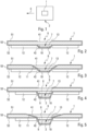
- the antenna cover 1 is intended to be attached to any type of supersonic or hypersonic vehicle 2, to cover at least one antenna 3 ( figure 1 ).
- the vehicle 2 is provided with one or more antennas 3 which can be used to transmit signals or to receive signals.
- the transmitted signals can be signals representative of information detected by sensors.
- the signals received may be signals representative of control commands for vehicle 2.
- the vehicle 2 can correspond to a missile, a space vehicle or a tank.
- FIG 1 schematically represents a vehicle 2 to which a bonnet 1 is fixed.
- the bonnet 1 can be fixed to the front of the vehicle 2 in the direction of movement E of the vehicle 2.
- the figure 2 represents the direction of movement E of the vehicle 2 by an arrow.
- the arrowhead is pointing in the direction of the front of vehicle 2.
- Hood 1 can also be attached to another portion of vehicle 2 or form the entire cover of vehicle 2.
- the cover 1 thus covers all or part of the supersonic or hypersonic vehicle 2 by providing a mechanical and aerodynamic junction.
- the cover 1 is made of composite material with a ceramic matrix reinforced with oxide fibers.
- Composite materials with a ceramic matrix are particularly suitable for withstanding temperatures up to a range ranging from 500° C. to 1100° C. Furthermore, they have the particularity of being electrically insulating and transparent in the frequency band of the electromagnetic waves used by the antenna or antennas 3 to carry the received and transmitted signals. This therefore avoids making openings facing the antenna or antennas 3, which avoids surface breaks generated by the presence of added elements, such as radomes. Thus, the aerodynamic shape of the cowl 1 is not degraded by surface ruptures. The radome or radomes are thus directly integrated into the cover 1.
- the fact of not having to fix radomes at the level of openings made in the cowl 1 avoids thermal bridge problems as well as problems of expansion, joining and fixing between different materials of the cowl 1 and the radomes .
- the cover 1 forming the entire cover of the vehicle 2 then fulfills the mechanical function of the entire cover as well as the function of transparency to electromagnetic waves of a radome.
- the mass of such a cover 1 is lower than if it had been made of metal.
- the density of such a composite material with a ceramic matrix is of the order of 2.5 whereas that of a metal is of the order of 8 to 10.
- the manufacturing cost is lower than if it had been made in composite material usually used such as a carbon ceramic matrix composite material reinforced with silicon carbide fibers.
- the oxide fibers correspond to aluminum oxide fibers (Al 2 O 3 ), zirconium oxide fibers (ZrO 2 ), silicon oxide fibers ( SiO 2 ), a mixture of oxide fibers such as mullite fibers.
- the ceramic matrix corresponds to an oxide matrix, configured to be transparent in an electromagnetic wave frequency band used by the antenna 3 or the antennas 3.
- the oxide matrix can be of the same nature as the fibers mentioned above.
- the oxide matrix corresponds to an aluminum oxide matrix, a zirconium oxide matrix or a silicon oxide matrix.
- the ceramic matrix corresponds to a geopolymer matrix, configured to be transparent in an electromagnetic wave frequency band used by the antenna 3 or the antennas 3.
- the geopolymer corresponds to one or more aluminum phosphates, to one or more silicates or to one or more aluminosilicates.
- the cover 1 can have a thickness of between 0.75 mm and 4 mm.
- the cover 1 has an outer surface 41 covered with at least one metal layer 51 except (or excepted) on one or more parts 6 of the cover 1 intended to come opposite the antenna or antennas 3 ( figures 2, 3, 4 and 5 ).
- the metallic layer 51 can be made of nickel, silver, copper and/or any other layer making it possible to create opacity in a frequency band of radar waves (leading to a metallic behavior of the vehicle structure 1).
- This metallic layer 51 makes it possible to ensure a flow of electrical charges on the surface of the cover 1. It can also make it possible to provide electromagnetic shielding and/or a certain stealthiness of the vehicle 2.
- the uncovered part(s) 6 allow the passage signals likely to be emitted or received by the antenna or antennas 3 of the vehicle 2.
- the cover 1 can also have an internal surface 42 covered with at least one metal layer 52 except on the part or parts 6 of the cover 1 intended to come opposite the antenna or antennas 3.
- the metal layer 52 is connected to the layer metallic layer 51.
- the metallic layer 51 and the metallic layer 52 are connected together by a metallic layer 53 covering a slice of the cover 1 between the external surface 41 and the internal surface 42. This metallic layer 53 makes it possible to establish an electrical connection between the two metal layers 51 and 52.
- the metal layers 51 and 52 have a sufficiently reduced thickness not to create surface ruptures.
- the metal layer 51 and the metal layer 52 have a thickness comprised in a range extending from 0.01 mm to 1 mm.
- the part or parts 6 not covered by the metal layers 51 and 52 thus play the role of radome of the antenna or antennas 3 intended to come opposite this part or these parts 6.
- the architecture or the thickness of the of parts 6 is adapted to ensure maximum transparency in a frequency band of the electromagnetic waves used by the antenna or antennas 3.
- the cover 1 is arranged so that a spacing 7 exists between, on the one hand, the internal surface 42 of the cover 1 and, on the other hand, the antenna 3 or each of the antennas 3 in a mounted position of the cover 1.
- the expression "mounted position of the cowl 1" means that the cowl 1 is mounted on the vehicle 2.
- the spacing 7 comprises an air gap 13. The thickness of the air gap 13 is adapted to limit the heating of the antenna or antennas 3 intended to come opposite the parts 3 not covered by the metal layer or layers 51 and 52.
- the air gap 13 has a thickness of between 1 mm and 5 mm.
- the thickness of the air gap can be limited to promote its integration.
- the spacing 7 may further comprise a layer of thermal insulation 8 covering the internal surface 42 of the cover 1 intended to come opposite the or each of the antennas 3 and a layer 9 of composite material with a ceramic matrix reinforced with oxide fibers covering the thermal insulation layer 8.
- the air gap 13 is thus located between, on the one hand, the antenna 3 or each of the antennas 3 and, on the other hand, the layer 9 of material composite.
- the thermal insulation layer 8 has a thickness resulting from a compromise between the level of transparency over the operating frequency band of the antenna or antennas 3 and the insulating capacities of the insulation.
- the thermal insulation layer 8 has a thickness of between 1 mm and 10 mm.
- the metallic layer 52 is configured to be connected (electrically) to a ground 10 of the antenna 3 or of each of the antennas 3 ( figures 2 and 4 ). This connection allows the evacuation of electrical charges which are liable to form on the internal surface 42 of the cover 1.
- the metallic layer 51 is configured to be connected (electrically) to the ground 10 of the antenna 3 or of each of the antennas 3 by an extension 11 through the cover 1 ( figures 3 and 5 ). This connection also allows the evacuation of electrical charges which are likely to form on the outer surface 41 of the cover 1.
- Cover 1 may further comprise a thermal protection layer 12 placed on the internal surface 42 of cover 1.
- Thermal protection layer 12 may cover metal layer 52.
- the thermal protection layer 12 has a thickness calculated to meet an internal temperature specification.
- the thermal protection layer 12 has a thickness of between 2 mm and 10 mm.
Landscapes
- Engineering & Computer Science (AREA)
- Aviation & Aerospace Engineering (AREA)
- Physics & Mathematics (AREA)
- Remote Sensing (AREA)
- Chemical & Material Sciences (AREA)
- Ceramic Engineering (AREA)
- Fluid Mechanics (AREA)
- Mechanical Engineering (AREA)
- General Physics & Mathematics (AREA)
- Astronomy & Astrophysics (AREA)
- Thermal Sciences (AREA)
- Health & Medical Sciences (AREA)
- Critical Care (AREA)
- Emergency Medicine (AREA)
- General Health & Medical Sciences (AREA)
- Details Of Aerials (AREA)
Description
- La présente invention concerne le domaine des véhicules, notamment des engins aéronautiques ou spatiaux croisant à des vitesses supersoniques ou hypersoniques. Plus particulièrement, elle concerne un capot d'antenne structurel et aérodynamique de forme complexe apte à intégrer au moins un radôme d'antenne et capable de résister à de hautes températures. Par ailleurs, ce capot d'antenne est capable de résister à de hautes températures.
- Lors d'un vol, la surface externe d'un véhicule supersonique ou hypersonique est susceptible d'atteindre des températures de plusieurs centaines de degrés Celsius. En effet, les frottements de l'air sur la surface externe du véhicule entraînent un échauffement important de cette surface externe. En outre, une rupture de la surface externe générée par la présence d'un élément rapporté sur cette surface externe peut créer un pont thermique vers la structure interne du véhicule, des problèmes de jonction, un frein aérodynamique ou encore un point d'arrêt qui devient extrêmement chaud.
- La question qui se pose dans ces conditions extrêmement sévères concerne l'intégration des radômes d'antenne et comment limiter les effets indésirables décrits ci-avant. Il convient tout d'abord de disposer de matériaux capables de résister à des températures comprises notamment entre 500°C et 1100°C.
- Une solution consiste à réaliser un capot dans un superalliage, tel qu'un « Inconel » ou un métal réfractaire, tel que le molybdène ou un alliage de titane, de zirconium et de molybdène (TZM). Des ouvertures sont alors pratiquées dans le capot en regard des zones pourvues d'une antenne. Des radômes en céramique transparentes et adaptées aux fréquences de fonctionnement des antennes sont alors rapportés et fixés au capot pour fermer chacune de ces ouvertures.
- Les superalliages ou les métaux réfractaires permettent au capot de résister à de fortes températures. Toutefois, les superalliages, tels que les « Inconels », présentent des propriétés mécaniques qui s'effondrent à partir de températures supérieures à 700°C ou 800°C. Une protection thermique supplémentaire doit donc être prévue pour accroître la résistance à de hautes températures, ce qui augmente la masse du capot. Par ailleurs, les métaux réfractaires possèdent des conductivités thermiques élevées, ce qui va favoriser les fuites thermiques susceptibles de chauffer la structure interne du véhicule.
- Une autre solution permettant au capot de résister à de hautes températures consiste à réaliser le capot en matériau composite céramique dont la matrice est en carbone et/ou en carbure de silicium et dont les fibres sont en carbone et/ou en carbure de silicium. Comme pour la solution précédente, des ouvertures sont pratiquées dans le capot en regard des zones pourvues d'une antenne. Des radômes en céramique transparents aux fréquences de fonctionnement des antennes sont alors fixés au capot.
- Le document
WO 2010/117474 décrit un radôme comportant une paroi externe en matériau composite céramique. - Un tel matériau composite céramique est capable de résister à des températures largement supérieures aux températures rencontrées lors du fonctionnement du véhicule. Toutefois, la fabrication de pièces de formes complexes et de grandes dimensions est généralement très coûteuse en raison des procédés de mise en oeuvre nécessaires comme le procédé de dépôt chimique en phase vapeur, autrement appelé procédé CVD (CVD pour « Chemical Vapor Déposition » en anglais), et les procédés associés. De plus, les géométries réalisables à partir de ces matériaux sont parfois limitées.
- Enfin, pour les deux solutions précitées, l'établissement d'une étanchéité entre le capot et le ou les radômes présente une réelle difficulté en raison de coefficients de dilatation différents entre les matériaux de ces derniers. Les dispositifs de fixation vont de plus générer des ruptures de surface et des points chauds supplémentaires.
- La présente invention a pour objet de pallier ces inconvénients en proposant un capot pour véhicule résistant à des contraintes mécaniques de vol et à de hautes températures sans altérer son étanchéité, ni sa transparence aux fréquences d'utilisation des antennes.
- A cet effet, l'invention concerne un capot d'antenne pour véhicule selon l'objet de la revendication 1.
- Selon l'invention, le capot est en matériau composite à matrice céramique renforcée par des fibres d'oxyde.
- Ainsi, grâce à l'invention, le capot d'antenne résiste à de hautes températures. Il reste en outre transparent aux fréquences d'utilisation des antennes du véhicule. Il ne présente donc pas de problème d'étanchéité car la création d'ouvertures fermées par des radômes fixées sur le capot n'est pas nécessaire.
- Selon un premier mode de réalisation, la matrice céramique du matériau composite correspond à une matrice en oxyde, configurée pour être transparente dans une bande de fréquences d'ondes électromagnétiques utilisées par la ou les antennes.
- Selon un deuxième mode de réalisation, la matrice céramique du matériau composite correspond à une matrice en géopolymère, configurée pour être transparente dans une bande de fréquences d'ondes électromagnétiques utilisées par la ou les antennes.
- En outre, le capot présente une surface externe recouverte d'au moins une première couche métallique sauf sur une ou des parties du capot destinées à venir en regard de la ou des antennes.
- De plus, le capot présente une surface interne recouverte d'au moins une deuxième couche métallique sauf sur la ou les parties du capot destinées à venir en regard de la ou des antennes, la deuxième couche métallique étant connectée à la première couche métallique.
- Par ailleurs, le capot est agencé pour qu'un espacement existe entre, d'une part, la surface interne du capot et, d'autre part, l'antenne ou chacune des antennes, l'espacement comprenant une lame d'air.
- Avantageusement, l'espacement comprend en outre une couche d'isolant thermique recouvrant la surface interne du capot destinée à venir en regard de la ou de chacune des antennes et une couche de matériau composite à matrice céramique renforcée par des fibres d'oxyde recouvrant la couche d'isolant thermique, la lame d'air se situant entre, d'une part, l'antenne ou chacune des antennes et, d'autre part la couche de composite.
- En outre, la deuxième couche métallique est configurée pour être connectée à une masse de l'antenne ou de chacune des antennes.
- De plus, la première couche métallique est configurée pour être connectée à la masse de l'antenne ou de chacune des antennes par un prolongement à travers le capot.
- Selon une particularité, le capot comprend en outre une couche de protection thermique disposée sur la surface interne du capot.
- L'invention concerne également un véhicule comportant au moins un capot d'antenne, tel que décrit ci-dessus.
- L'invention, avec ses caractéristiques et avantages, ressortira plus clairement à la lecture de la description faite en référence aux dessins annexés dans lesquels :
- la
figure 1 représente schématiquement un véhicule équipé du capot, - la
figure 2 représente schématiquement une coupe transversale du capot selon une première variante, - la
figure 3 représente schématiquement une coupe transversale du capot selon une deuxième variante, - la
figure 4 représente schématiquement une coupe transversale du capot selon une troisième variante, - la
figure 5 représente schématiquement une coupe transversale du capot selon une quatrième variante. - Le capot 1 d'antenne est destiné à être fixé à tout type de véhicule 2 supersonique ou hypersonique, pour couvrir au moins une antenne 3 (
figure 1 ). Le véhicule 2 est pourvu d'une ou de plusieurs antennes 3 qui peuvent servir à émettre des signaux ou à recevoir des signaux. Les signaux émis peuvent être des signaux représentatifs d'informations détectées par des capteurs. Les signaux reçus peuvent être des signaux représentatifs d'ordre de commande du véhicule 2. - De façon non limitative, le véhicule 2 peut correspondre à un missile, un véhicule spatial ou un réservoir.
- La
figure 1 représente schématiquement un véhicule 2 sur lequel est fixé un capot 1. Le capot 1 peut être fixé à l'avant du véhicule 2 dans le sens de déplacement E du véhicule 2. Lafigure 2 représente le sens de déplacement E du véhicule 2 par une flèche. La pointe de la flèche est dirigée dans le sens de l'avant du véhicule 2. Le capot 1 peut également être fixé à une autre portion du véhicule 2 ou former toute la couverture du véhicule 2. - Le capot 1 recouvre ainsi tout ou partie du véhicule 2 supersonique ou hypersonique en assurant une jonction mécanique et aérodynamique.
- Le capot 1 est fabriqué en matériau composite à matrice céramique renforcée par des fibres d'oxyde.
- Les matériaux composites à matrice céramique, notamment à matrice en oxyde ou en géopolymère, sont particulièrement adaptés pour résister jusqu'à des températures comprises dans une plage allant de 500°C à 1100°C. Par ailleurs, ils possèdent la particularité d'être électriquement isolants et transparents dans la bande de fréquences des ondes électromagnétiques utilisées par l'antenne ou les antennes 3 pour porter les signaux reçus et émis. Cela évite donc de pratiquer des ouvertures en regard de la ou des antennes 3, ce qui évite des ruptures de surface générées par la présence d'éléments rapportés, tels que des radômes. Ainsi, la forme aérodynamique du capot 1 n'est pas dégradée par des ruptures de surface. Le ou les radômes sont ainsi directement intégrés dans le capot 1.
- Par ailleurs, le fait ne de pas avoir à fixer des radômes au niveau d'ouvertures pratiquées dans le capot 1 évite des problématiques de pont thermique ainsi que des problématiques de dilatation, de jointure et de fixation entre matériaux différents du capot 1 et des radômes. En formant toute la couverture du véhicule 2, on évite toute zone de fixation entre différents éléments destinés à former un capot. Le capot 1 formant toute la couverture du véhicule 2 remplit alors la fonction mécanique de l'ensemble du capotage ainsi que la fonction de transparence aux ondes électromagnétiques d'un radôme.
- De plus, la masse d'un tel capot 1 est plus faible que s'il avait été fabriqué en métal. En effet, la densité d'un tel matériau composite à matrice céramique est de l'ordre de 2,5 alors que celle d'un métal est de l'ordre de 8 à 10. En outre, le coût de fabrication est moindre que s'il avait été fabriqué en matériau composite usuellement utilisé tel qu'un matériau composite en matrice céramique de carbone renforcée par des fibres en carbure de silicium.
- Par exemple et de façon non limitative, les fibres d'oxyde correspondent à des fibres d'oxyde d'aluminium (Al2O3), des fibres d'oxyde de zirconium (ZrO2), des fibres d'oxyde de silicium (SiO2), un mélange de fibres d'oxyde tel que des fibres de mullite.
- Selon un premier mode de réalisation, la matrice céramique correspond à une matrice en oxyde, configurée pour être transparente dans une bande de fréquences d'ondes électromagnétiques utilisées par l'antenne 3 ou les antennes 3.
- Par exemple et de façon non limitative, la matrice en oxyde peut être de même nature que les fibres citées ci-dessus. Par exemple, la matrice en oxyde correspond à une matrice en oxyde d'aluminium, une matrice en oxyde de zirconium ou une matrice en oxyde de silicium.
- Selon un deuxième mode de réalisation, la matrice céramique correspond à une matrice en géopolymère, configurée pour être transparente dans une bande de fréquences d'ondes électromagnétiques utilisées par l'antenne 3 ou les antennes 3.
- Par exemple et de façon non limitative, le géopolymère correspond à un ou des phosphates d'aluminium, à un ou des silicates ou à un ou des aluminosilicates.
- De façon non limitative, le capot 1 peut présenter une épaisseur comprise entre 0,75 mm et 4 mm.
- Avantageusement, le capot 1 présente une surface externe 41 recouverte d'au moins une couche métallique 51 sauf (ou excepté) sur une ou des parties 6 du capot 1 destinées à venir en regard de la ou des antennes 3 (
figures 2, 3, 4 et 5 ). - Par exemple et de façon non limitative, la couche métallique 51 peut être en nickel, en argent, en cuivre et/ou toute autre couche permettant de créer une opacité dans une bande de fréquences d'ondes radar (conduisant à un comportement métallique de la structure du véhicule 1).
- Cette couche métallique 51 permet d'assurer un écoulement des charges électriques sur la surface du capot 1. Elle peut également permettre d'assurer un blindage électromagnétique et/ou une certaine furtivité du véhicule 2. La ou les parties 6 non recouvertes permettent le passage des signaux susceptibles d'être émis ou reçus par la ou les antennes 3 du véhicule 2.
- Le capot 1 peut également présenter une surface interne 42 recouverte d'au moins une couche métallique 52 sauf sur la ou les parties 6 du capot 1 destinées à venir en regard de la ou des antennes 3. La couche métallique 52 est connectée à la couche métallique 51. Par exemple la couche métallique 51 et la couche métallique 52 sont reliées ensemble par une couche métallique 53 recouvrant une tranche du capot 1 entre la surface externe 41 et la surface interne 42. Cette couche métallique 53 permet d'établir une connexion électrique entre les deux couches métalliques 51 et 52.
- Les couches métalliques 51 et 52 présentent une épaisseur suffisamment réduite pour ne pas créer de ruptures de surface.
- De façon non limitative, la couche métallique 51 et la couche métallique 52 présentent une épaisseur comprise dans une plage allant de 0,01 mm à 1 mm.
- La ou les parties 6 non recouvertes par les couches métalliques 51 et 52 jouent ainsi le rôle de radôme de la ou des antennes 3 destinées à venir en regard de cette partie ou de ces parties 6. L'architecture ou l'épaisseur de la ou des parties 6 est adaptée pour assurer un maximum de transparence dans une bande de fréquences des ondes électromagnétiques utilisées par la ou les antennes 3.
- Selon une variante de réalisation (
figures 2 et 3 ), le capot 1 est agencé pour qu'un espacement 7 existe entre, d'une part, la surface interne 42 du capot 1 et, d'autre part, l'antenne 3 ou chacune des antennes 3 dans une position montée du capot 1. L'expression « position montée du capot 1 » signifie que le capot 1 est monté sur le véhicule 2. De façon avantageuse, l'espacement 7 comprend à une lame d'air 13. L'épaisseur de la lame d'air 13 est adaptée pour limiter l'échauffement de la ou des antennes 3 destinées à venir en regard des parties 3 non recouvertes par la ou les couches métalliques 51 et 52. - Par exemple et de façon non limitative, la lame d'air 13 présente une épaisseur comprise entre 1 mm et 5 mm. L'épaisseur de la lame d'air peut être limitée pour favoriser son intégration.
- Selon une autre variante de réalisation (
figures 4 et 5 ), l'espacement 7 peut comprendre en outre une couche d'isolant thermique 8 recouvrant la surface interne 42 du capot 1 destinée à venir en regard de la ou de chacune des antennes 3 et une couche 9 de matériau composite à matrice céramique renforcée par des fibres d'oxyde recouvrant la couche d'isolant thermique 8. La lame d'air 13 se situe ainsi entre, d'une part, l'antenne 3 ou chacune des antennes 3 et, d'autre part la couche 9 de matériau composite. - La couche d'isolant thermique 8 présente une épaisseur résultant d'un compromis entre le niveau de transparence sur la bande de fréquences de fonctionnement de la ou des antennes 3 et les capacités d'isolation de l'isolant. Par exemple et de façon non limitative, la couche d'isolant thermique 8 présente une épaisseur comprise entre 1 mm et 10 mm.
- De préférence, la couche métallique 52 est configurée pour être connectée (électriquement) à une masse 10 de l'antenne 3 ou de chacune des antennes 3 (
figures 2 et 4 ). Cette connexion permet l'évacuation des charges électriques qui sont susceptibles de se former sur la surface interne 42 du capot 1. - De même, la couche métallique 51 est configurée pour être connectée (électriquement) à la masse 10 de l'antenne 3 ou de chacune des antennes 3 par un prolongement 11 à travers le capot 1 (
figures 3 et 5 ). Cette connexion permet également l'évacuation des charges électriques qui sont susceptibles de se former sur la surface externe 41 du capot 1. - Le capot 1 peut comprendre en outre une couche de protection thermique 12 disposée sur la surface interne 42 du capot 1. La couche de protection thermique 12 peut recouvrir la couche métallique 52.
- La couche de protection thermique 12 présente une épaisseur calculée pour répondre à une spécification de température interne. Par exemple et de façon non limitative, la couche de protection thermique 12 présente une épaisseur comprise entre 2 mm et 10 mm.
Claims (9)
- Capot d'antenne pour véhicule (2), le capot (1) étant destiné à couvrir au moins une antenne (3) fixée sur le véhicule (2), le capot (1) étant en matériau composite à matrice céramique renforcée par des fibres d'oxyde, le capot (1) présentant une surface externe (41) recouverte d'au moins une première couche métallique (51) sauf sur une ou des parties (6) du capot (1) destinées à venir en regard de la ou des antennes (3), caractérisé en ce que le capot (1) présent une surface interne (42) recouverte d'au moins une deuxième couche métallique (52) sauf sur la ou les parties (6) du capot (1) destinées à venir en regard de la ou des antennes (3), la deuxième couche métallique (52) étant connectée à la première couche métallique (51) par une couche métallique (53) recouvrant une tranche du capot (1) entre la surface externe (41) et la surface interne (42).
- Capot selon la revendication 1,
caractérisé en ce que la matrice céramique du matériau composite correspond à une matrice en oxyde, configurée pour être transparente dans une bande de fréquences d'ondes électromagnétiques utilisées par la ou les antennes (3). - Capot selon la revendication 1,
caractérisé en ce que la matrice céramique du matériau composite correspond à une matrice en géopolymère, configurée pour être transparente dans une bande de fréquences d'ondes électromagnétiques utilisées par la ou les antennes (3). - Capot selon l'une quelconque des revendications 1 à 3,
caractérisé en ce que le capot (1) est agencé pour qu'un espacement (7) existe entre, d'une part, la surface interne (42) du capot (1) et, d'autre part, l'antenne (3) ou chacune des antennes (3) dans une position montée du capot (1), l'espacement (7) comprenant une lame d'air (13). - Capot selon la revendication 4,
caractérisé en ce que l'espacement (7) comprend en outre une couche d'isolant thermique (8) recouvrant la surface interne (42) du capot (1) destinée à venir en regard de la ou de chacune des antennes (3) et une couche (9) de matériau composite à matrice céramique renforcée par des fibres d'oxyde recouvrant la couche d'isolant thermique (8), la lame d'air (13) se situant entre, d'une part, l'antenne (3) ou chacune des antennes (3) et, d'autre part la couche (9) de matériau composite. - Capot selon l'une quelconque des revendications 1 à 5,
caractérisé en ce que la deuxième couche métallique (52) est configurée pour être connectée à une masse (10) de l'antenne (3) ou de chacune des antennes (3). - Capot selon l'une quelconque des revendications 1 à 6,
caractérisé en ce que la première couche métallique (51) est configurée pour être connectée à la masse (10) de l'antenne (3) ou de chacune des antennes (3) par un prolongement (11) à travers le capot (1). - Capot selon l'une quelconque des revendications 1 à 7,
caractérisé en ce qu'il comprend en outre une couche de protection thermique (12) disposée sur la surface interne (42) du capot (1). - Véhicule,
caractérisé en ce qu'il comprend au moins un capot (1) tel que spécifié selon l'une quelconque des revendications 1 à 8.
Applications Claiming Priority (1)
| Application Number | Priority Date | Filing Date | Title |
|---|---|---|---|
| FR1908398A FR3099132B1 (fr) | 2019-07-26 | 2019-07-26 | Capot pour vehicule, en particulier pour vehicule supersonique ou hypersonique |
Publications (3)
| Publication Number | Publication Date |
|---|---|
| EP3771035A1 EP3771035A1 (fr) | 2021-01-27 |
| EP3771035C0 EP3771035C0 (fr) | 2023-08-02 |
| EP3771035B1 true EP3771035B1 (fr) | 2023-08-02 |
Family
ID=69468616
Family Applications (1)
| Application Number | Title | Priority Date | Filing Date |
|---|---|---|---|
| EP20185160.7A Active EP3771035B1 (fr) | 2019-07-26 | 2020-07-10 | Capot pour véhicule, en particulier pour véhicule supersonique ou hypersonique |
Country Status (7)
| Country | Link |
|---|---|
| US (1) | US12009590B2 (fr) |
| EP (1) | EP3771035B1 (fr) |
| ES (1) | ES2955602T3 (fr) |
| FR (1) | FR3099132B1 (fr) |
| IL (1) | IL289794B2 (fr) |
| PL (1) | PL3771035T3 (fr) |
| WO (1) | WO2021019139A1 (fr) |
Families Citing this family (4)
| Publication number | Priority date | Publication date | Assignee | Title |
|---|---|---|---|---|
| FR3099132B1 (fr) * | 2019-07-26 | 2022-01-28 | Mbda France | Capot pour vehicule, en particulier pour vehicule supersonique ou hypersonique |
| US12009568B1 (en) * | 2020-03-20 | 2024-06-11 | Hrl Laboratories, Llc | Thermal protection system including high temperature radio frequency aperture |
| US20220173491A1 (en) * | 2020-07-03 | 2022-06-02 | James Martin | Fire resistant antenna apparatuses, systems and methods |
| CN114292130B (zh) * | 2021-12-21 | 2022-11-15 | 山东工业陶瓷研究设计院有限公司 | 一种陶瓷件及其加工方法 |
Citations (1)
| Publication number | Priority date | Publication date | Assignee | Title |
|---|---|---|---|---|
| US20160031568A1 (en) * | 2014-07-30 | 2016-02-04 | Mitsubishi Aircraft Corporation | Aircraft antenna cover, aircraft member cover, aircraft, and rain erosion boot for aircraft |
Family Cites Families (33)
| Publication number | Priority date | Publication date | Assignee | Title |
|---|---|---|---|---|
| US4520364A (en) * | 1983-04-19 | 1985-05-28 | The United States Of America As Represented By The Secretary Of The Air Force | Attachment method-ceramic radome to metal body |
| CA2077125C (fr) * | 1992-01-13 | 2002-04-09 | Louis B. Brydon | Couvercle autoporteur convexe pour vaisseau spatial |
| US6037023A (en) * | 1994-07-08 | 2000-03-14 | Raytheon Company | Broadband composite structure fabricated from inorganic polymer matrix reinforced with glass or ceramic woven cloth |
| US5483894A (en) * | 1994-12-27 | 1996-01-16 | Hughes Missile Systems Company | Integral missile antenna-fuselage assembly |
| US7420523B1 (en) * | 2005-09-14 | 2008-09-02 | Radant Technologies, Inc. | B-sandwich radome fabrication |
| US8599095B2 (en) * | 2005-12-08 | 2013-12-03 | Raytheon Company | Broadband ballistic resistant radome |
| US7817099B2 (en) * | 2005-12-08 | 2010-10-19 | Raytheon Company | Broadband ballistic resistant radome |
| US7681834B2 (en) * | 2006-03-31 | 2010-03-23 | Raytheon Company | Composite missile nose cone |
| US7847749B2 (en) * | 2006-05-24 | 2010-12-07 | Wavebender, Inc. | Integrated waveguide cavity antenna and reflector RF feed |
| US8715439B2 (en) * | 2008-03-07 | 2014-05-06 | The Boeing Company | Method for making hybrid metal-ceramic matrix composite structures and structures made thereby |
| US8054239B2 (en) * | 2008-10-24 | 2011-11-08 | Raytheon Company | Honeycomb-backed armored radome |
| US8130167B2 (en) * | 2009-04-10 | 2012-03-06 | Coi Ceramics, Inc. | Radomes, aircraft and spacecraft including such radomes, and methods of forming radomes |
| IL201812A (en) * | 2009-10-29 | 2015-01-29 | Elta Systems Ltd | Wave-guided antenna |
| US8765230B1 (en) * | 2009-12-01 | 2014-07-01 | The Boeing Company | Thermal barrier coated RF radomes and method |
| EP2400591A1 (fr) * | 2010-06-14 | 2011-12-28 | Saint-Gobain Glass France | Structure d'antenne avec rapport signal/bruit amélioré |
| US9368859B2 (en) * | 2012-10-09 | 2016-06-14 | Saab Ab | Method for integrating an antenna with a vehicle fuselage |
| US10153546B2 (en) * | 2013-07-02 | 2018-12-11 | Dsm Ip Assets B.V. | Composite antiballistic radome walls and methods of making the same |
| US10381731B2 (en) * | 2014-02-17 | 2019-08-13 | Ge Global Sourcing Llc | Aerial camera system, method for identifying route-related hazards, and microstrip antenna |
| US9419333B1 (en) * | 2014-04-10 | 2016-08-16 | The Boeing Company | Stacks having hermetic capping layers over porous ceramic matrix composite structures |
| US9711845B2 (en) * | 2014-07-21 | 2017-07-18 | The Boeing Company | Aerial vehicle radome assembly and methods for assembling the same |
| US10103444B2 (en) * | 2016-04-06 | 2018-10-16 | Raytheon Company | Conformal broadband directional ½ flared notch radiator antenna array |
| US10644391B2 (en) * | 2017-12-19 | 2020-05-05 | The Boeing Company | Cavity antenna with radome |
| BR112020013113A2 (pt) * | 2017-12-28 | 2020-12-01 | Prima Sole Components S.P.A. | placa decorativa transparente de radar para a grade frontal de um veículo a motor |
| US10871564B2 (en) * | 2018-08-03 | 2020-12-22 | Veoneer Us, Inc. | Vehicular radar assembly |
| FR3093961B1 (fr) * | 2019-03-22 | 2021-03-05 | Plastic Omnium Cie | Pièce de carrosserie de véhicule comprenant au moins une antenne directive |
| FR3099132B1 (fr) * | 2019-07-26 | 2022-01-28 | Mbda France | Capot pour vehicule, en particulier pour vehicule supersonique ou hypersonique |
| US11276933B2 (en) * | 2019-11-06 | 2022-03-15 | The Boeing Company | High-gain antenna with cavity between feed line and ground plane |
| KR102872953B1 (ko) * | 2019-11-26 | 2025-10-17 | 현대자동차주식회사 | 전파투과용 커버 및 이를 포함하는 도어 아웃사이드 핸들 |
| CN111934080A (zh) * | 2020-06-22 | 2020-11-13 | 安徽虚怀信息技术有限公司 | 一种车联网5g天线 |
| DE102020209307A1 (de) * | 2020-07-23 | 2022-01-27 | Robert Bosch Gesellschaft mit beschränkter Haftung | Radarsensor mit Hohlleiterstruktur |
| US11664584B2 (en) * | 2020-07-31 | 2023-05-30 | Te Connectivity Solutions Gmbh | Monopole antenna assembly |
| EP4105678A1 (fr) * | 2021-06-18 | 2022-12-21 | HELLA Saturnus Slovenija d.o.o. | Couvercle éclairé pour émetteur et récepteur électromagnétiques |
| CN114784489B (zh) * | 2022-03-31 | 2024-01-16 | 华为技术有限公司 | 波导天线组件、雷达、终端和波导天线组件的制备方法 |
-
2019
- 2019-07-26 FR FR1908398A patent/FR3099132B1/fr active Active
-
2020
- 2020-07-10 EP EP20185160.7A patent/EP3771035B1/fr active Active
- 2020-07-10 ES ES20185160T patent/ES2955602T3/es active Active
- 2020-07-10 WO PCT/FR2020/051253 patent/WO2021019139A1/fr not_active Ceased
- 2020-07-10 PL PL20185160.7T patent/PL3771035T3/pl unknown
- 2020-07-10 US US17/626,906 patent/US12009590B2/en active Active
- 2020-07-10 IL IL289794A patent/IL289794B2/en unknown
Patent Citations (1)
| Publication number | Priority date | Publication date | Assignee | Title |
|---|---|---|---|---|
| US20160031568A1 (en) * | 2014-07-30 | 2016-02-04 | Mitsubishi Aircraft Corporation | Aircraft antenna cover, aircraft member cover, aircraft, and rain erosion boot for aircraft |
Also Published As
| Publication number | Publication date |
|---|---|
| IL289794B1 (en) | 2025-01-01 |
| EP3771035A1 (fr) | 2021-01-27 |
| US20220263235A1 (en) | 2022-08-18 |
| IL289794A (en) | 2022-03-01 |
| ES2955602T3 (es) | 2023-12-04 |
| EP3771035C0 (fr) | 2023-08-02 |
| IL289794B2 (en) | 2025-05-01 |
| FR3099132B1 (fr) | 2022-01-28 |
| FR3099132A1 (fr) | 2021-01-29 |
| WO2021019139A1 (fr) | 2021-02-04 |
| PL3771035T3 (pl) | 2023-11-20 |
| US12009590B2 (en) | 2024-06-11 |
Similar Documents
| Publication | Publication Date | Title |
|---|---|---|
| EP3771035B1 (fr) | Capot pour véhicule, en particulier pour véhicule supersonique ou hypersonique | |
| EP2303696B1 (fr) | Equipement avionique comprenant un systeme de drainage d'un courant de foudre genere par une decharge orageuse sur un aeronef | |
| EP2906471A1 (fr) | Elément constitutif d'une nacelle à protection contre le givre améliorée | |
| EP1412693A1 (fr) | Blindage composite milticouches | |
| CA2781013A1 (fr) | Carenage aerodynamique arriere d'un mat de liaison d'un moteur d'aeronef | |
| FR3022885A1 (fr) | Paroi structurante de missile, en particulier pour coiffe de protection thermique | |
| EP0723897B1 (fr) | Vitrage feuilleté équipé d'un détecteur | |
| FR3033746A1 (fr) | Ecran de protection acoustique pour moteur de vehicule automobile | |
| EP2994686B1 (fr) | Systeme d'attachement pour panneaux de protection thermique | |
| CH703393B1 (fr) | Guides pour ondes électromagnétiques et procédé de fabrication de ces guides. | |
| EP3383740B1 (fr) | Piece isolante metallique | |
| US12017779B2 (en) | Integrated microwave thermal anti-icing system | |
| EP4348275B1 (fr) | Sonde de mesure aerodynamique | |
| WO2007060376A1 (fr) | Instrument optique comprenant une cavite d'entree dans laquelle est place un miroir | |
| EP4455542B1 (fr) | Réservoir comprenant des enceintes interne et externe ainsi qu au moins un conduit traversant lesdites enceintes et suivant une trajectoire courbe entre lesdites enceintes | |
| EP4462012B1 (fr) | Réservoir comprenant des enceintes internes et externes ainsi qu'au moins un conduit traversant au moins une plaque de fermeture déformable | |
| EP3166177B1 (fr) | Fenêtre hyperfréquence | |
| CA3083138A1 (fr) | Vitrage chauffant en matiere plastique structurale | |
| EP4303053A1 (fr) | Véhicule doté d'une patte de fixation d'un réservoir d'urée protégée de la chaleur | |
| EP4450936A1 (fr) | Système de mesure d'au moins une grandeur thermique configuré pour limiter l'impact des transferts thermiques par convection | |
| WO2008152311A2 (fr) | Dispositif d'isolation d'un collecteur d'echappement | |
| CA2057762A1 (fr) | Dispositif de liaison mecanique entre un materiau ceramique et un metal notamment pour la realisation d'un bord d'attaque d'une gouverne | |
| FR2507511A1 (fr) | Dispositif et procede pour inhiber, lors du refroidissement, la production d'une retassure a la surface superieure d'un lingot | |
| FR2945793A1 (fr) | Dispositif de protection thermique a reglettes mobiles. |
Legal Events
| Date | Code | Title | Description |
|---|---|---|---|
| PUAI | Public reference made under article 153(3) epc to a published international application that has entered the european phase |
Free format text: ORIGINAL CODE: 0009012 |
|
| STAA | Information on the status of an ep patent application or granted ep patent |
Free format text: STATUS: THE APPLICATION HAS BEEN PUBLISHED |
|
| AK | Designated contracting states |
Kind code of ref document: A1 Designated state(s): AL AT BE BG CH CY CZ DE DK EE ES FI FR GB GR HR HU IE IS IT LI LT LU LV MC MK MT NL NO PL PT RO RS SE SI SK SM TR |
|
| AX | Request for extension of the european patent |
Extension state: BA ME |
|
| STAA | Information on the status of an ep patent application or granted ep patent |
Free format text: STATUS: REQUEST FOR EXAMINATION WAS MADE |
|
| 17P | Request for examination filed |
Effective date: 20210422 |
|
| RBV | Designated contracting states (corrected) |
Designated state(s): AL AT BE BG CH CY CZ DE DK EE ES FI FR GB GR HR HU IE IS IT LI LT LU LV MC MK MT NL NO PL PT RO RS SE SI SK SM TR |
|
| STAA | Information on the status of an ep patent application or granted ep patent |
Free format text: STATUS: EXAMINATION IS IN PROGRESS |
|
| 17Q | First examination report despatched |
Effective date: 20220426 |
|
| GRAP | Despatch of communication of intention to grant a patent |
Free format text: ORIGINAL CODE: EPIDOSNIGR1 |
|
| STAA | Information on the status of an ep patent application or granted ep patent |
Free format text: STATUS: GRANT OF PATENT IS INTENDED |
|
| INTG | Intention to grant announced |
Effective date: 20230428 |
|
| GRAS | Grant fee paid |
Free format text: ORIGINAL CODE: EPIDOSNIGR3 |
|
| GRAA | (expected) grant |
Free format text: ORIGINAL CODE: 0009210 |
|
| STAA | Information on the status of an ep patent application or granted ep patent |
Free format text: STATUS: THE PATENT HAS BEEN GRANTED |
|
| AK | Designated contracting states |
Kind code of ref document: B1 Designated state(s): AL AT BE BG CH CY CZ DE DK EE ES FI FR GB GR HR HU IE IS IT LI LT LU LV MC MK MT NL NO PL PT RO RS SE SI SK SM TR |
|
| REG | Reference to a national code |
Ref country code: GB Ref legal event code: FG4D Free format text: NOT ENGLISH |
|
| REG | Reference to a national code |
Ref country code: CH Ref legal event code: EP |
|
| REG | Reference to a national code |
Ref country code: DE Ref legal event code: R096 Ref document number: 602020014795 Country of ref document: DE |
|
| REG | Reference to a national code |
Ref country code: IE Ref legal event code: FG4D Free format text: LANGUAGE OF EP DOCUMENT: FRENCH |
|
| U01 | Request for unitary effect filed |
Effective date: 20230810 |
|
| U07 | Unitary effect registered |
Designated state(s): AT BE BG DE DK EE FI FR IT LT LU LV MT NL PT SE SI Effective date: 20230816 |
|
| REG | Reference to a national code |
Ref country code: ES Ref legal event code: FG2A Ref document number: 2955602 Country of ref document: ES Kind code of ref document: T3 Effective date: 20231204 |
|
| PG25 | Lapsed in a contracting state [announced via postgrant information from national office to epo] |
Ref country code: GR Free format text: LAPSE BECAUSE OF FAILURE TO SUBMIT A TRANSLATION OF THE DESCRIPTION OR TO PAY THE FEE WITHIN THE PRESCRIBED TIME-LIMIT Effective date: 20231103 |
|
| PG25 | Lapsed in a contracting state [announced via postgrant information from national office to epo] |
Ref country code: IS Free format text: LAPSE BECAUSE OF FAILURE TO SUBMIT A TRANSLATION OF THE DESCRIPTION OR TO PAY THE FEE WITHIN THE PRESCRIBED TIME-LIMIT Effective date: 20231202 |
|
| PG25 | Lapsed in a contracting state [announced via postgrant information from national office to epo] |
Ref country code: RS Free format text: LAPSE BECAUSE OF FAILURE TO SUBMIT A TRANSLATION OF THE DESCRIPTION OR TO PAY THE FEE WITHIN THE PRESCRIBED TIME-LIMIT Effective date: 20230802 Ref country code: NO Free format text: LAPSE BECAUSE OF FAILURE TO SUBMIT A TRANSLATION OF THE DESCRIPTION OR TO PAY THE FEE WITHIN THE PRESCRIBED TIME-LIMIT Effective date: 20231102 Ref country code: IS Free format text: LAPSE BECAUSE OF FAILURE TO SUBMIT A TRANSLATION OF THE DESCRIPTION OR TO PAY THE FEE WITHIN THE PRESCRIBED TIME-LIMIT Effective date: 20231202 Ref country code: HR Free format text: LAPSE BECAUSE OF FAILURE TO SUBMIT A TRANSLATION OF THE DESCRIPTION OR TO PAY THE FEE WITHIN THE PRESCRIBED TIME-LIMIT Effective date: 20230802 Ref country code: GR Free format text: LAPSE BECAUSE OF FAILURE TO SUBMIT A TRANSLATION OF THE DESCRIPTION OR TO PAY THE FEE WITHIN THE PRESCRIBED TIME-LIMIT Effective date: 20231103 |
|
| PG25 | Lapsed in a contracting state [announced via postgrant information from national office to epo] |
Ref country code: SM Free format text: LAPSE BECAUSE OF FAILURE TO SUBMIT A TRANSLATION OF THE DESCRIPTION OR TO PAY THE FEE WITHIN THE PRESCRIBED TIME-LIMIT Effective date: 20230802 Ref country code: RO Free format text: LAPSE BECAUSE OF FAILURE TO SUBMIT A TRANSLATION OF THE DESCRIPTION OR TO PAY THE FEE WITHIN THE PRESCRIBED TIME-LIMIT Effective date: 20230802 Ref country code: CZ Free format text: LAPSE BECAUSE OF FAILURE TO SUBMIT A TRANSLATION OF THE DESCRIPTION OR TO PAY THE FEE WITHIN THE PRESCRIBED TIME-LIMIT Effective date: 20230802 Ref country code: SK Free format text: LAPSE BECAUSE OF FAILURE TO SUBMIT A TRANSLATION OF THE DESCRIPTION OR TO PAY THE FEE WITHIN THE PRESCRIBED TIME-LIMIT Effective date: 20230802 |
|
| REG | Reference to a national code |
Ref country code: DE Ref legal event code: R097 Ref document number: 602020014795 Country of ref document: DE |
|
| PLBE | No opposition filed within time limit |
Free format text: ORIGINAL CODE: 0009261 |
|
| STAA | Information on the status of an ep patent application or granted ep patent |
Free format text: STATUS: NO OPPOSITION FILED WITHIN TIME LIMIT |
|
| 26N | No opposition filed |
Effective date: 20240503 |
|
| U20 | Renewal fee for the european patent with unitary effect paid |
Year of fee payment: 5 Effective date: 20240701 |
|
| PG25 | Lapsed in a contracting state [announced via postgrant information from national office to epo] |
Ref country code: MC Free format text: LAPSE BECAUSE OF FAILURE TO SUBMIT A TRANSLATION OF THE DESCRIPTION OR TO PAY THE FEE WITHIN THE PRESCRIBED TIME-LIMIT Effective date: 20230802 |
|
| REG | Reference to a national code |
Ref country code: CH Ref legal event code: PL |
|
| PG25 | Lapsed in a contracting state [announced via postgrant information from national office to epo] |
Ref country code: CH Free format text: LAPSE BECAUSE OF NON-PAYMENT OF DUE FEES Effective date: 20240731 |
|
| PGFP | Annual fee paid to national office [announced via postgrant information from national office to epo] |
Ref country code: PL Payment date: 20250630 Year of fee payment: 6 |
|
| PG25 | Lapsed in a contracting state [announced via postgrant information from national office to epo] |
Ref country code: IE Free format text: LAPSE BECAUSE OF NON-PAYMENT OF DUE FEES Effective date: 20240710 |
|
| U20 | Renewal fee for the european patent with unitary effect paid |
Year of fee payment: 6 Effective date: 20250630 |
|
| PGFP | Annual fee paid to national office [announced via postgrant information from national office to epo] |
Ref country code: ES Payment date: 20250811 Year of fee payment: 6 |
|
| PGFP | Annual fee paid to national office [announced via postgrant information from national office to epo] |
Ref country code: GB Payment date: 20250723 Year of fee payment: 6 |
|
| PG25 | Lapsed in a contracting state [announced via postgrant information from national office to epo] |
Ref country code: CY Free format text: LAPSE BECAUSE OF FAILURE TO SUBMIT A TRANSLATION OF THE DESCRIPTION OR TO PAY THE FEE WITHIN THE PRESCRIBED TIME-LIMIT; INVALID AB INITIO Effective date: 20200710 |
|
| PG25 | Lapsed in a contracting state [announced via postgrant information from national office to epo] |
Ref country code: HU Free format text: LAPSE BECAUSE OF FAILURE TO SUBMIT A TRANSLATION OF THE DESCRIPTION OR TO PAY THE FEE WITHIN THE PRESCRIBED TIME-LIMIT; INVALID AB INITIO Effective date: 20200710 |