EP3771085B1 - Dispositif de conversion d'énergie et procédé de commande de dispositif de conversion d'énergie - Google Patents
Dispositif de conversion d'énergie et procédé de commande de dispositif de conversion d'énergie Download PDFInfo
- Publication number
- EP3771085B1 EP3771085B1 EP19771896.8A EP19771896A EP3771085B1 EP 3771085 B1 EP3771085 B1 EP 3771085B1 EP 19771896 A EP19771896 A EP 19771896A EP 3771085 B1 EP3771085 B1 EP 3771085B1
- Authority
- EP
- European Patent Office
- Prior art keywords
- power
- carrier frequency
- power supply
- power conversion
- coupled
- Prior art date
- Legal status (The legal status is an assumption and is not a legal conclusion. Google has not performed a legal analysis and makes no representation as to the accuracy of the status listed.)
- Active
Links
Images



Classifications
-
- H—ELECTRICITY
- H02—GENERATION; CONVERSION OR DISTRIBUTION OF ELECTRIC POWER
- H02M—APPARATUS FOR CONVERSION BETWEEN AC AND AC, BETWEEN AC AND DC, OR BETWEEN DC AND DC, AND FOR USE WITH MAINS OR SIMILAR POWER SUPPLY SYSTEMS; CONVERSION OF DC OR AC INPUT POWER INTO SURGE OUTPUT POWER; CONTROL OR REGULATION THEREOF
- H02M1/00—Details of apparatus for conversion
- H02M1/10—Arrangements incorporating converting means for enabling loads to be operated at will from different kinds of power supplies, e.g. from AC or DC
-
- B—PERFORMING OPERATIONS; TRANSPORTING
- B60—VEHICLES IN GENERAL
- B60L—PROPULSION OF ELECTRICALLY-PROPELLED VEHICLES; SUPPLYING ELECTRIC POWER FOR AUXILIARY EQUIPMENT OF ELECTRICALLY-PROPELLED VEHICLES; ELECTRODYNAMIC BRAKE SYSTEMS FOR VEHICLES IN GENERAL; MAGNETIC SUSPENSION OR LEVITATION FOR VEHICLES; MONITORING OPERATING VARIABLES OF ELECTRICALLY-PROPELLED VEHICLES; ELECTRIC SAFETY DEVICES FOR ELECTRICALLY-PROPELLED VEHICLES
- B60L50/00—Electric propulsion with power supplied within the vehicle
- B60L50/10—Electric propulsion with power supplied within the vehicle using propulsion power supplied by engine-driven generators, e.g. generators driven by combustion engines
- B60L50/13—Electric propulsion with power supplied within the vehicle using propulsion power supplied by engine-driven generators, e.g. generators driven by combustion engines using AC generators and AC motors
-
- B—PERFORMING OPERATIONS; TRANSPORTING
- B60—VEHICLES IN GENERAL
- B60L—PROPULSION OF ELECTRICALLY-PROPELLED VEHICLES; SUPPLYING ELECTRIC POWER FOR AUXILIARY EQUIPMENT OF ELECTRICALLY-PROPELLED VEHICLES; ELECTRODYNAMIC BRAKE SYSTEMS FOR VEHICLES IN GENERAL; MAGNETIC SUSPENSION OR LEVITATION FOR VEHICLES; MONITORING OPERATING VARIABLES OF ELECTRICALLY-PROPELLED VEHICLES; ELECTRIC SAFETY DEVICES FOR ELECTRICALLY-PROPELLED VEHICLES
- B60L9/00—Electric propulsion with power supply external to the vehicle
- B60L9/16—Electric propulsion with power supply external to the vehicle using AC induction motors
- B60L9/24—Electric propulsion with power supply external to the vehicle using AC induction motors fed from AC supply lines
-
- B—PERFORMING OPERATIONS; TRANSPORTING
- B60—VEHICLES IN GENERAL
- B60L—PROPULSION OF ELECTRICALLY-PROPELLED VEHICLES; SUPPLYING ELECTRIC POWER FOR AUXILIARY EQUIPMENT OF ELECTRICALLY-PROPELLED VEHICLES; ELECTRODYNAMIC BRAKE SYSTEMS FOR VEHICLES IN GENERAL; MAGNETIC SUSPENSION OR LEVITATION FOR VEHICLES; MONITORING OPERATING VARIABLES OF ELECTRICALLY-PROPELLED VEHICLES; ELECTRIC SAFETY DEVICES FOR ELECTRICALLY-PROPELLED VEHICLES
- B60L9/00—Electric propulsion with power supply external to the vehicle
- B60L9/16—Electric propulsion with power supply external to the vehicle using AC induction motors
- B60L9/30—Electric propulsion with power supply external to the vehicle using AC induction motors fed from different kinds of power-supply lines
-
- H—ELECTRICITY
- H02—GENERATION; CONVERSION OR DISTRIBUTION OF ELECTRIC POWER
- H02M—APPARATUS FOR CONVERSION BETWEEN AC AND AC, BETWEEN AC AND DC, OR BETWEEN DC AND DC, AND FOR USE WITH MAINS OR SIMILAR POWER SUPPLY SYSTEMS; CONVERSION OF DC OR AC INPUT POWER INTO SURGE OUTPUT POWER; CONTROL OR REGULATION THEREOF
- H02M5/00—Conversion of AC power input into AC power output, e.g. for change of voltage, for change of frequency, for change of number of phases
- H02M5/40—Conversion of AC power input into AC power output, e.g. for change of voltage, for change of frequency, for change of number of phases with intermediate conversion into DC
- H02M5/42—Conversion of AC power input into AC power output, e.g. for change of voltage, for change of frequency, for change of number of phases with intermediate conversion into DC by static converters
- H02M5/44—Conversion of AC power input into AC power output, e.g. for change of voltage, for change of frequency, for change of number of phases with intermediate conversion into DC by static converters using discharge tubes or semiconductor devices to convert the intermediate DC into AC
- H02M5/453—Conversion of AC power input into AC power output, e.g. for change of voltage, for change of frequency, for change of number of phases with intermediate conversion into DC by static converters using discharge tubes or semiconductor devices to convert the intermediate DC into AC using devices of a triode or transistor type requiring continuous application of a control signal
- H02M5/458—Conversion of AC power input into AC power output, e.g. for change of voltage, for change of frequency, for change of number of phases with intermediate conversion into DC by static converters using discharge tubes or semiconductor devices to convert the intermediate DC into AC using devices of a triode or transistor type requiring continuous application of a control signal using semiconductor devices only
- H02M5/4585—Conversion of AC power input into AC power output, e.g. for change of voltage, for change of frequency, for change of number of phases with intermediate conversion into DC by static converters using discharge tubes or semiconductor devices to convert the intermediate DC into AC using devices of a triode or transistor type requiring continuous application of a control signal using semiconductor devices only having a rectifier with controlled elements
-
- H—ELECTRICITY
- H02—GENERATION; CONVERSION OR DISTRIBUTION OF ELECTRIC POWER
- H02M—APPARATUS FOR CONVERSION BETWEEN AC AND AC, BETWEEN AC AND DC, OR BETWEEN DC AND DC, AND FOR USE WITH MAINS OR SIMILAR POWER SUPPLY SYSTEMS; CONVERSION OF DC OR AC INPUT POWER INTO SURGE OUTPUT POWER; CONTROL OR REGULATION THEREOF
- H02M7/00—Conversion of AC power input into DC power output; Conversion of DC power input into AC power output
- H02M7/02—Conversion of AC power input into DC power output without possibility of reversal
- H02M7/04—Conversion of AC power input into DC power output without possibility of reversal by static converters
- H02M7/12—Conversion of AC power input into DC power output without possibility of reversal by static converters using discharge tubes with control electrode or semiconductor devices with control electrode
- H02M7/21—Conversion of AC power input into DC power output without possibility of reversal by static converters using discharge tubes with control electrode or semiconductor devices with control electrode using devices of a triode or transistor type requiring continuous application of a control signal
- H02M7/217—Conversion of AC power input into DC power output without possibility of reversal by static converters using discharge tubes with control electrode or semiconductor devices with control electrode using devices of a triode or transistor type requiring continuous application of a control signal using semiconductor devices only
- H02M7/23—Conversion of AC power input into DC power output without possibility of reversal by static converters using discharge tubes with control electrode or semiconductor devices with control electrode using devices of a triode or transistor type requiring continuous application of a control signal using semiconductor devices only arranged for operation in parallel
-
- B—PERFORMING OPERATIONS; TRANSPORTING
- B60—VEHICLES IN GENERAL
- B60L—PROPULSION OF ELECTRICALLY-PROPELLED VEHICLES; SUPPLYING ELECTRIC POWER FOR AUXILIARY EQUIPMENT OF ELECTRICALLY-PROPELLED VEHICLES; ELECTRODYNAMIC BRAKE SYSTEMS FOR VEHICLES IN GENERAL; MAGNETIC SUSPENSION OR LEVITATION FOR VEHICLES; MONITORING OPERATING VARIABLES OF ELECTRICALLY-PROPELLED VEHICLES; ELECTRIC SAFETY DEVICES FOR ELECTRICALLY-PROPELLED VEHICLES
- B60L2200/00—Type of vehicles
- B60L2200/26—Rail vehicles
-
- B—PERFORMING OPERATIONS; TRANSPORTING
- B60—VEHICLES IN GENERAL
- B60L—PROPULSION OF ELECTRICALLY-PROPELLED VEHICLES; SUPPLYING ELECTRIC POWER FOR AUXILIARY EQUIPMENT OF ELECTRICALLY-PROPELLED VEHICLES; ELECTRODYNAMIC BRAKE SYSTEMS FOR VEHICLES IN GENERAL; MAGNETIC SUSPENSION OR LEVITATION FOR VEHICLES; MONITORING OPERATING VARIABLES OF ELECTRICALLY-PROPELLED VEHICLES; ELECTRIC SAFETY DEVICES FOR ELECTRICALLY-PROPELLED VEHICLES
- B60L2220/00—Electrical machine types; Structures or applications thereof
- B60L2220/40—Electrical machine applications
- B60L2220/42—Electrical machine applications with use of more than one motor
-
- H—ELECTRICITY
- H02—GENERATION; CONVERSION OR DISTRIBUTION OF ELECTRIC POWER
- H02M—APPARATUS FOR CONVERSION BETWEEN AC AND AC, BETWEEN AC AND DC, OR BETWEEN DC AND DC, AND FOR USE WITH MAINS OR SIMILAR POWER SUPPLY SYSTEMS; CONVERSION OF DC OR AC INPUT POWER INTO SURGE OUTPUT POWER; CONTROL OR REGULATION THEREOF
- H02M5/00—Conversion of AC power input into AC power output, e.g. for change of voltage, for change of frequency, for change of number of phases
- H02M5/02—Conversion of AC power input into AC power output, e.g. for change of voltage, for change of frequency, for change of number of phases without intermediate conversion into DC
- H02M5/04—Conversion of AC power input into AC power output, e.g. for change of voltage, for change of frequency, for change of number of phases without intermediate conversion into DC by static converters
- H02M5/10—Conversion of AC power input into AC power output, e.g. for change of voltage, for change of frequency, for change of number of phases without intermediate conversion into DC by static converters using transformers
- H02M5/14—Conversion of AC power input into AC power output, e.g. for change of voltage, for change of frequency, for change of number of phases without intermediate conversion into DC by static converters using transformers for conversion between circuits of different phase number
-
- Y—GENERAL TAGGING OF NEW TECHNOLOGICAL DEVELOPMENTS; GENERAL TAGGING OF CROSS-SECTIONAL TECHNOLOGIES SPANNING OVER SEVERAL SECTIONS OF THE IPC; TECHNICAL SUBJECTS COVERED BY FORMER USPC CROSS-REFERENCE ART COLLECTIONS [XRACs] AND DIGESTS
- Y02—TECHNOLOGIES OR APPLICATIONS FOR MITIGATION OR ADAPTATION AGAINST CLIMATE CHANGE
- Y02T—CLIMATE CHANGE MITIGATION TECHNOLOGIES RELATED TO TRANSPORTATION
- Y02T10/00—Road transport of goods or passengers
- Y02T10/60—Other road transportation technologies with climate change mitigation effect
- Y02T10/64—Electric machine technologies in electromobility
-
- Y—GENERAL TAGGING OF NEW TECHNOLOGICAL DEVELOPMENTS; GENERAL TAGGING OF CROSS-SECTIONAL TECHNOLOGIES SPANNING OVER SEVERAL SECTIONS OF THE IPC; TECHNICAL SUBJECTS COVERED BY FORMER USPC CROSS-REFERENCE ART COLLECTIONS [XRACs] AND DIGESTS
- Y02—TECHNOLOGIES OR APPLICATIONS FOR MITIGATION OR ADAPTATION AGAINST CLIMATE CHANGE
- Y02T—CLIMATE CHANGE MITIGATION TECHNOLOGIES RELATED TO TRANSPORTATION
- Y02T10/00—Road transport of goods or passengers
- Y02T10/60—Other road transportation technologies with climate change mitigation effect
- Y02T10/7072—Electromobility specific charging systems or methods for batteries, ultracapacitors, supercapacitors or double-layer capacitors
Definitions
- the present invention relates to a power conversion device and a power conversion device control method.
- the power conversion device generally includes a converter that converts a single-phase AC power supplied from an overhead line to a DC power, and an inverter that drives an electric motor using the converted DC power as a power source. While the converter causes a semiconductor element (for example, IGBT) to perform a switching operation, an influence of harmonics due to the operation propagates to the overhead line to adversely affect a railway infrastructure (signal device and the like) coupled via the overhead line.
- a semiconductor element for example, IGBT
- Patent Literature 1 discloses a rail vehicle that includes a power generation unit and the rail vehicle is configured to receive a supply of an AC power from also a power generation unit other than an overhead line.
- Patent Literature 1 discloses that a converter in a power conversion device is coupled to each of a plurality of AC power supplies, the converter includes means to be coupled to the overhead line and means to be coupled to an electric generator driven by an engine, and the converter performs a power conversion operation corresponding to the coupled AC power supply.
- Patent Literature 1 Japanese Unexamined Patent Application Publication No. 2014-140294
- US 2017/033711 proposes a power conversion device and AC electric-vehicle drive system.
- JP 2000 004503A proposes an electric car control device.
- the control can be simplified by employing the same switching operation regardless the respective AC power supplies.
- the influence of the harmonics on the railway infrastructure and thermal effect on a switching element need to be considered, while in the case of coupled to the electric generator, a harmonic content of the current to the electric generator and the thermal effect on the switching element need to be considered.
- a problem such as inductive disturbance to the railway infrastructure, reduction in operational efficiency of the electric generator due to the harmonic current, and shortened lifespan of the switching element, causes. Since these points are not considered on the rail vehicle disclosed in Patent Literature 1, a problem arises in that the influence of the harmonics due to the switching operation of the converter cannot be avoided.
- a power conversion device according to a first aspect of the present invention is provided in claim 1.
- a power conversion device control method according to a second aspect of the present invention is provided in claim 5.
- the influence of the harmonics due to the switching operation of the converter can be avoided.
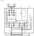
- Fig. 1 is a drawing illustrating a configuration of a drive system 9.
- the drive system 9 of this embodiment is coupled to a power collector 1 via a main transformer 11.
- the power collector 1 takes in a single-phase AC power from an overhead line (not illustrated), which is coupled to an electrical substation to function as a single-phase AC power supply, and outputs the single-phase AC power to a winding on a high voltage side of the main transformer 11.
- Two windings are disposed on a low voltage side of the main transformer 11, the single-phase AC power from the overhead line is stepped down and supplied to each winding.
- Another end of the winding on the high voltage side of the main transformer 11 is coupled to a rail 19.
- the drive system 9 includes a power generation unit 6, a power conversion device 7, a contactor 13, and a contactor 12.
- the power generation unit 6 includes an engine and an electric generator driven by the engine, and functions as a three-phase AC power supply that supplies a three-phase AC power.
- the contactor 13 is coupled between a three-phase current output of the power generation unit 6 and the power conversion device 7.
- the contactor 12 is coupled between the main transformer 11 and the power conversion device 7.
- the power conversion device 7 includes power supply power converter circuits 21 and 22, a smoothing capacitor 3, an electric motor driving converter circuit 4, and a drive control device 20.
- the smoothing capacitor 3 is coupled to direct-current sides of the power supply power converter circuits 21, 22 and smooths a DC voltage.
- the power supply power converter circuits 21 and 22 each include switching circuits to convert the AC power into the DC power for two phases.
- the switching circuit includes series-connected two connection bodies, and in the connection body, a semiconductor element (for example, IGBT) having a selfarc-extinguishing ability and a diode are coupled in anti-parallel.
- the power supply power converter circuit 21 and the power supply power converter circuit 22 are also collectively referred to as a converter.
- the electric motor driving converter circuit 4 includes a plurality of semiconductor elements in combination, and drives a main motor 5 having voltages at both ends of the smoothing capacitor 3 as voltage sources.
- the drive control device 20 controls the switching operations of the power supply power converter circuits 21 and 22.
- Fig. 2 is a drawing illustrating an exemplary configuration when the drive system 9 is mounted to a train.
- Fig. 2 illustrates an embodiment where the four drive systems 9 illustrated in Fig. 1 are mounted to four train cars.
- the power collector 1 and the main transformer 11 are mounted to each of the first and the last cars, and the single-phase AC power from the overhead line is supplied from the power collectors 1 to the respective main transformers 11 via switches 15, 16.
- the two drive systems 9 on the first car side receive the single-phase AC power (by the amount of two windings) from the main transformer 11 mounted to the first car.
- the two drive systems 9 on the last car side receive the single-phase AC power (by the amount of two windings) from the main transformer 11 mounted to the last car.
- the power conversion device 7 (Traction Converter) illustrated in Fig. 2 includes the power supply power converter circuits 21 and 22, the smoothing capacitor 3, the electric motor driving converter circuit 4, and the drive control device 20 illustrated in Fig. 1 .
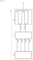
- Fig. 3 is a drawing illustrating a configuration of the drive control device 20.
- the drive control device 20 includes a status monitoring unit 26, an operation command unit 27, and a PWM converter control unit 28.
- the status monitoring unit 26 is coupled to an upper control unit (not illustrated), and monitors whether the power conversion device 7 is supplied with the single-phase AC power from the overhead line or supplied with the three-phase AC power from the power generation unit 6. Then, when the AC power supply coupled to the power conversion device 7 is the overhead line and the single-phase AC power from the overhead line is supplied to the power conversion device 7, a signal 261 indicating a state where the AC power supply is the overhead line is output to the operation command unit 27.
- a signal 262 indicating a state where the AC power supply is the engine is output to the operation command unit 27. Furthermore, the status monitoring unit 26 outputs a signal 263 to instruct a converter start on the overhead line to the operation command unit 27 when starting the converter with the single-phase AC power from the overhead line, and outputs a signal 264 to instruct a converter start on the engine to the operation command unit 27 when starting the converter with the three-phase AC power from the power generation unit 6.
- the operation command unit 27 outputs an overhead line switching operation signal 271 or an engine switching operation signal 272 to the PWM converter control unit 28 corresponding to a combination of the signals 261 to 264 input from the status monitoring unit 26. Specifically, when the signal 261 indicating the state where the AC power supply is the overhead line and the signal 263 instructing the converter start on the overhead line are input, the overhead line switching operation signal 271 is used as an output signal to the PWM converter control unit 28 corresponding to these input signals. Meanwhile, when the signal 262 indicating the state where the AC power supply is the engine and the signal 264 instructing the converter start on the engine are input, the engine switching operation signal 272 is used as an output signal to the PWM converter control unit 28 corresponding to these input signals.
- the carrier frequency F COHL [Hz] is a frequency that does not overlap with an operating frequency of a device installed in the railway infrastructure and a frequency above which thermal effects on the semiconductor element included in the converter become unacceptable.
- Fig. 4 is a flowchart illustrating an operation of the operation command unit 27 in the drive control device.
- Step S41 whether the signal 261 indicating the state where the AC power supply is the overhead line is ON (signal present), and the signal 262 indicating the state where the AC power supply is the engine is OFF (no signal), and the signal 263 instructing the converter start on the overhead line is ON, and the signal 264 instructing the converter start on the engine is OFF or not is determined.
- Step S41 whether the signal 261 indicating the state where the AC power supply is the overhead line is ON (signal present), and the signal 262 indicating the state where the AC power supply is the engine is OFF (no signal), and the signal 263 instructing the converter start on the overhead line is ON, and the signal 264 instructing the converter start on the engine is OFF or not is determined.
- Step S42 the process proceeds to Step S42.
- Step S42 the overhead line switching operation signal 271 is turned ON, and the engine switching operation signal 272 is turned OFF.
- the process proceeds to Step S43.
- Step S43 whether the signal 261 indicating the state where the AC power supply is the overhead line is OFF, and the signal 262 indicating the state where the AC power supply is the engine is ON, and the signal 263 instructing the converter start on the overhead line is OFF, and the signal 264 instructing the converter start on the engine is ON or not is determined.
- the process proceeds to Step S44.
- Step S44 the overhead line switching operation signal 271 is turned OFF, and the engine switching operation signal 272 is turned ON.
- the process proceeds to Step S45.
- Step S45 the overhead line switching operation signal 271 is turned OFF, and the engine switching operation signal 272 is turned OFF.
- the process of the flowchart illustrated in Fig. 4 ends after the processes of Steps S42, 43, and 45. The process of the flowchart illustrated in Fig. 4 is periodically repeated.
- Fig. 5 is a flowchart illustrating an operation of the PWM converter control unit 28 in the drive control device 20.
- Step S51 whether the overhead line switching operation signal 271 is ON and the engine switching operation signal 272 is OFF or not is determined.
- Step S52 the process proceeds to Step S52.
- Step S54 whether the overhead line switching operation signal 271 is OFF and the engine switching operation signal 272 is ON or not is determined.
- Step S57 the PWM pulse signal is not output.
- the process of the flowchart illustrated in Fig. 5 ends after the processes of Steps S53, 56, and 57.
- the process of the flowchart illustrated in Fig. 5 is periodically repeated.
- the horizontal axis indicates the frequency, regions indicated by diagonal lines are regions influenced when superimposed on the carrier frequency of the converter.
- Fig. 6(A) illustrates a case where the embodiment of the present invention is not applied
- Fig. 6(B) illustrates a case where the embodiment of the present invention is applied.
- an operating frequency band I of infrastructure side devices includes an operating frequency band a used by an infrastructure side device A and an operating frequency band b used by an infrastructure side device B.
- a carrier frequency band C1 of the switching element of the converter when operating on the overhead line includes a region s1 where the thermal effect caused when the carrier frequency of the converter is increased becomes unacceptable.
- a carrier frequency band E where the harmonics are included in the current flowing through the electric generator includes a region e where an amount of the harmonics of the current flowing through the electric generator becomes unacceptable.
- a carrier frequency band C2 of the switching element of the converter when operating on the engine includes a region s2 where the thermal effect caused when the carrier frequency of the converter is increased becomes unacceptable.
- the carrier frequencies that avoid the restraint condition A1 on the overhead line and the restraint condition A2 on the engine are not present.
- the amount of the harmonics of the current flowing through the electric generator means an amount of the harmonic current of the first harmonic or more.
- the harmonic current is included in the current flowing through the electric generator and generated by the switching operation of the converter. While a heat generation amount of the electric generator is increased by making the current flow through the electric generator, its acceptable value is decided in the specification of the electric generator.
- the carrier frequency F COHL [Hz] is selected as the carrier frequency
- F CENG [Hz] is selected as the carrier frequency
- Fig. 7(A) illustrates a case where the embodiment of the present invention is not applied
- Fig. 7(B) illustrates a case where the embodiment of the present invention is applied.
- the operating frequency band I of the infrastructure side devices includes the operating frequency band a used by the infrastructure side device A and the operating frequency band b used by the infrastructure side device B.
- the carrier frequency band C1 of the switching element of the converter when operating on the overhead line includes the region s1 where the thermal effect caused when the carrier frequency of the converter is increased becomes unacceptable.
- the carrier frequency band E where the harmonics are included in the current flowing through the electric generator includes the region e where the amount of the harmonics of the current flowing through the electric generator becomes unacceptable.
- the carrier frequency band C2 of the switching element of the converter when operating on the engine includes the region s2 where the thermal effect caused when the carrier frequency of the converter is increased becomes unacceptable.
- the carrier frequency F COHL [Hz] is selected as the carrier frequency
- the carrier frequency F CENG [Hz] is selected as the carrier frequency
- the switching operation at the carrier frequency F COHL for satisfying the restraint condition of the power conversion operation on the overhead line and the switching operation at the carrier frequency F CENG for satisfying the restraint condition of the power conversion operation on the engine can be each controlled. Therefore, the switching operation of the converter (power supply power converter circuits 21 and 22) is changed corresponding to the AC power supply, thereby ensuring satisfying the different restraint conditions of the power conversion operations on the respective AC power supplies.
- the power supply power converter circuit 21 and the power supply power converter circuit 22 include switching circuits for two phases that include series-connected two connection bodies, and in the connection body, a semiconductor element and a diode are coupled in anti-parallel.
- the example illustrated in Fig. 8 has a configuration where the power supply power converter circuit 21 similar to that illustrated in Fig. 1 is coupled to one winding on the low voltage side of the main transformer 11, and further a power converter circuit 23 for one phase is coupled.
- Other configurations are similar to those of Fig. 1 .
- the power supply power converter circuit 21 similar to that illustrated in Fig. 1 is coupled to one winding on the low voltage side of the main transformer 11, and further, a power converter circuit 24 to which diodes are series-connected is applied instead of the power converter circuit 23 for one phase in the embodiment illustrated in Fig. 8 .
- Other configurations are similar to those of Fig. 1 .
- the power conversion device 7 includes the power supply power converter circuits 21 and 22 (converter) and the drive control device 20.
- the power supply power converter circuits 21 and 22 are coupled to the overhead line as the single-phase AC power supply or the power generation unit 6 as the three-phase AC power supply via the contactor 12, 13.
- the power supply power converter circuits 21 and 22 perform the power conversion operations to convert the single-phase AC power supplied from the overhead line or the three-phase AC power supplied from the power generation unit 6 into the DC power.
- the drive control device 20 controls each of the carrier frequency F COHL and the carrier frequency F CENG .
- the carrier frequency F COHL is the carrier frequency in the power conversion operations of the power supply power converter circuits 21 and 22 when the overhead line is coupled.
- the carrier frequency F CENG is the carrier frequency in the power conversion operations of the power supply power converter circuits 21 and 22 when the power generation unit 6 is coupled. Accordingly, the influence of the harmonics due to the switching operation of the converter can be avoided.
- the status monitoring unit 26, the operation command unit 27, the PWM converter control unit 28, the overhead line converter control unit 281, the engine converter control unit 282 may be replaced by status monitoring means, operation command means, converter control means, overhead line converter control means, engine converter control means, respectively.
- the power converter circuit and the drive control unit may be replaced by power converter means and drive control means, respectively.
Landscapes
- Engineering & Computer Science (AREA)
- Power Engineering (AREA)
- Transportation (AREA)
- Mechanical Engineering (AREA)
- Life Sciences & Earth Sciences (AREA)
- Sustainable Development (AREA)
- Sustainable Energy (AREA)
- Electric Propulsion And Braking For Vehicles (AREA)
- Inverter Devices (AREA)
- Rectifiers (AREA)
Claims (8)
- Dispositif de conversion de puissance (7) pour un système d'enregistrement d'un train comprenant :
un circuit convertisseur de puissance (4) configuré pour être couplé à une première alimentation électrique CA ou une deuxième alimentation électrique CA (6) par l'intermédiaire d'un contacteur (12, 13), le circuit convertisseur de puissance étant configuré pour effectuer une opération de conversion de puissance pour convertir une première énergie CA fournie depuis la première alimentation électrique CA ou une deuxième énergie CA fournie depuis la deuxième alimentation électrique CA en une énergie CC, la première énergie CA étant une énergie CA fournie depuis une ligne aérienne, et la deuxième énergie CA étant une énergie CA générée par l'entraînement d'un générateur électrique (G) par un fonctionnement d'un moteur ;
caractérisé en ce qu'une unité de commande d'entraînement (20) est configurée pour réguler une fréquence de porteuse dans l'opération de conversion de puissance du circuit convertisseur de puissance (4) de sorte que lorsque la première énergie CA est fournie depuis la première alimentation électrique CA, une fréquence de porteuse est choisie parmi une première bande de fréquence de porteuse qui ne chevauche pas une fréquence de fonctionnement d'un dispositif installé dans une infrastructure ferroviaire couplée par l'intermédiaire de la ligne aérienne et au-dessus de laquelle les effets thermiques sur un élément semi-conducteur inclus dans le convertisseur sont inacceptables, et lorsque la deuxième énergie CA est fournie depuis la deuxième alimentation électrique CA (6), une fréquence de porteuse est choisie parmi une deuxième bande de fréquence de porteuse dans laquelle un courant harmonique dans le générateur électrique est acceptable et au-dessus de laquelle les effets thermiques sur l'élément semi-conducteur inclus dans le convertisseur sont inacceptables. - Dispositif de conversion de puissance selon la revendication 1,
dans lequel l'unité de commande d'entraînement (20) est configurée pour entraîner le circuit convertisseur de puissance (4) par l'opération de conversion de puissance à une première fréquence de porteuse lorsque la première alimentation électrique CA est couplée, et pour entraîner le circuit convertisseur de puissance par l'opération de conversion de puissance à une deuxième fréquence de porteuse différente de la première fréquence de porteuse lorsque la deuxième alimentation électrique CA (6) est couplée. - Dispositif de conversion de puissance selon la revendication 1 ou la revendication 2,
dans lequel la fréquence de porteuse dans l'opération de conversion de puissance du circuit convertisseur de puissance (4) lorsque la première alimentation électrique CA est couplée a une valeur inférieure à une valeur de la fréquence de porteuse dans l'opération de conversion de puissance du circuit convertisseur de puissance lorsque la deuxième alimentation électrique CA (6) est couplée. - Dispositif de conversion de puissance selon la revendication 1 ou la revendication 2,
dans lequel la fréquence de porteuse dans l'opération de conversion de puissance du circuit convertisseur de puissance (4) lorsque la première alimentation électrique CA est couplée a une valeur supérieure à une valeur de la fréquence de porteuse dans l'opération de conversion de puissance du circuit convertisseur de puissance lorsque la deuxième alimentation électrique CA (6) est couplée. - Procédé de commande de dispositif de conversion de puissance dans lequel une fréquence de porteuse pour l'opération de conversion de puissance d'un circuit convertisseur de puissance pour un système d'entraînement d'un train est régulée,dans lequel une opération de conversion de puissance est effectuée à une première fréquence de porteuse lorsqu'une première alimentation électrique CA est couplée au circuit convertisseur de puissance (4) par l'intermédiaire d'un contacteur (12), l'opération de conversion de puissance convertissant une première énergie CA fournie depuis la première alimentation électrique CA en une énergie CC, la première énergie CA étant une énergie CA fournie depuis une ligne aérienne, et la première fréquence de porteuse étant choisie parmi une première bande de fréquence de porteuse qui ne chevauche par une fréquence de fonctionnement d'un dispositif installé dans une infrastructure ferroviaire couplée par l'intermédiaire de la ligne aérienne et au-dessus de laquelle les effets thermiques sur un élément semi-conducteur inclus dans le convertisseur sont inacceptables, etl'opération de conversion de puissance est effectuée à une deuxième fréquence de porteuse lorsqu'une deuxième alimentation électrique CA (6) est couplée au circuit convertisseur de puissance (4) par l'intermédiaire d'un contacteur (13), l'opération de conversion de puissance convertissant une deuxième énergie CA fournie depuis la deuxième alimentation électrique CA en énergie CC, la deuxième énergie CA étant une énergie CA générée par entraînement d'un générateur électrique (G) par un fonctionnement d'un moteur, et la deuxième fréquence de porteuse étant choisie parmi une deuxième bande de fréquence de porteuse dans laquelle un courant harmonique dans le générateur électrique est acceptable et au-dessus de laquelle les effets thermiques sur l'élément semi-conducteur inclus dans le convertisseur sont inacceptables.
- Procédé de commande de dispositif de conversion de puissance selon la revendication 5, dans lequel la première fréquence de porteuse et la deuxième fréquence de porteuse sont des fréquences de porteuses différentes.
- Procédé de commande de dispositif de conversion de puissance selon la revendication 5 ou la revendication 6,
dans lequel la première fréquence de porteuse dans l'opération de conversion de puissance du circuit convertisseur de puissance (4) lorsque la première alimentation électrique CA est couplée a une valeur inférieure à une valeur de la deuxième fréquence de porteuse dans l'opération de conversion de puissance du circuit convertisseur de puissance lorsque la deuxième alimentation électrique CA (6) est couplée. - Procédé de commande de dispositif de conversion de puissance selon la revendication 5 ou la revendication 6,
dans lequel la première fréquence de porteuse dans l'opération de conversion de puissance du circuit convertisseur de puissance (4) lorsque la première alimentation électrique CA est couplée a une valeur supérieure à une valeur de la deuxième fréquence de porteuse dans l'opération de conversion de puissance du circuit convertisseur de puissance lorsque la deuxième alimentation électrique CA (6) est couplée.
Applications Claiming Priority (2)
| Application Number | Priority Date | Filing Date | Title |
|---|---|---|---|
| JP2018057294 | 2018-03-23 | ||
| PCT/JP2019/001523 WO2019181162A1 (fr) | 2018-03-23 | 2019-01-18 | Dispositif de conversion d'énergie et procédé de commande de dispositif de conversion d'énergie |
Publications (3)
| Publication Number | Publication Date |
|---|---|
| EP3771085A1 EP3771085A1 (fr) | 2021-01-27 |
| EP3771085A4 EP3771085A4 (fr) | 2021-12-01 |
| EP3771085B1 true EP3771085B1 (fr) | 2023-03-15 |
Family
ID=67988352
Family Applications (1)
| Application Number | Title | Priority Date | Filing Date |
|---|---|---|---|
| EP19771896.8A Active EP3771085B1 (fr) | 2018-03-23 | 2019-01-18 | Dispositif de conversion d'énergie et procédé de commande de dispositif de conversion d'énergie |
Country Status (3)
| Country | Link |
|---|---|
| EP (1) | EP3771085B1 (fr) |
| JP (1) | JP7001811B2 (fr) |
| WO (1) | WO2019181162A1 (fr) |
Family Cites Families (7)
| Publication number | Priority date | Publication date | Assignee | Title |
|---|---|---|---|---|
| JPH09121548A (ja) * | 1995-10-25 | 1997-05-06 | Shinko Electric Co Ltd | 正弦波pwmコンバータのスイッチング制御回路 |
| JP3675124B2 (ja) * | 1997-09-18 | 2005-07-27 | 富士電機システムズ株式会社 | パルス幅変調制御コンバータの制御装置 |
| JP2000004503A (ja) * | 1998-06-15 | 2000-01-07 | Toshiba Corp | 電気車制御装置 |
| BR112013019259B1 (pt) * | 2011-01-31 | 2020-09-24 | Hitachi, Ltd. | Sistema de acionamento e trem multi-carro |
| JP5938739B2 (ja) * | 2011-11-24 | 2016-06-22 | 国立大学法人長岡技術科学大学 | 電力変換装置 |
| JP2014057384A (ja) * | 2012-09-11 | 2014-03-27 | Panasonic Corp | 電気機器を含む電源システム |
| JP5951143B2 (ja) * | 2013-11-28 | 2016-07-13 | 三菱電機株式会社 | 電力変換装置および交流電気車駆動システム |
-
2019
- 2019-01-18 JP JP2020507374A patent/JP7001811B2/ja active Active
- 2019-01-18 WO PCT/JP2019/001523 patent/WO2019181162A1/fr not_active Ceased
- 2019-01-18 EP EP19771896.8A patent/EP3771085B1/fr active Active
Also Published As
| Publication number | Publication date |
|---|---|
| JP7001811B2 (ja) | 2022-02-04 |
| WO2019181162A1 (fr) | 2019-09-26 |
| JPWO2019181162A1 (ja) | 2021-04-01 |
| EP3771085A4 (fr) | 2021-12-01 |
| EP3771085A1 (fr) | 2021-01-27 |
Similar Documents
| Publication | Publication Date | Title |
|---|---|---|
| EP2695763B1 (fr) | Convertisseur de puissance de traction pour véhicule ferroviaire multisystème | |
| US20140203559A1 (en) | Connection for improved current balancing between parallel bridge circuits | |
| US10075097B2 (en) | Power conversion device and AC electric-vehicle drive system | |
| US20200180451A1 (en) | Power conversion device | |
| JP2017225279A (ja) | 電力変換システム | |
| JP5038339B2 (ja) | 電力供給方法及び交直流電車用電源システム | |
| JP2009232672A (ja) | モータ駆動システム | |
| WO2011004588A1 (fr) | Dispositif de commande de véhicule électrique | |
| US8183804B2 (en) | AC motor driving circuit and electric car driving circuit | |
| JP2008236889A (ja) | インバータ装置 | |
| JP2015128353A (ja) | 交流電気車制御システム | |
| EP3771085A1 (fr) | Dispositif de conversion d'énergie et procédé de commande de dispositif de conversion d'énergie | |
| JP6393643B2 (ja) | 車両駆動システム | |
| JP4838031B2 (ja) | 多重インバータの制御システム | |
| HK1206495A1 (en) | Station building power supply device | |
| JP2017022827A (ja) | 補助電源装置 | |
| KR100511645B1 (ko) | 회생 전동차 대응한 직렬 디씨 전압 급전 시스템 | |
| WO2022009794A1 (fr) | Système de conversion de puissance, son procédé de commande et véhicule ferroviaire équipé de celui-ci | |
| JP6157977B2 (ja) | 鉄道車両、及び車両用電力変換システム | |
| JP7019056B2 (ja) | 駆動制御装置および駆動制御方法、当該駆動制御装置を搭載する鉄道車両 | |
| KR100511644B1 (ko) | 회생 전동차 대응한 병렬 디씨 전압 급전 시스템 | |
| EP4545345A1 (fr) | Système d'alimentation électrique pour un véhicule ferroviaire | |
| EP4459855A1 (fr) | Convertisseur et procédé de conversion d'une puissance ca moyenne tension en une puissance cc basse tension | |
| US11975616B2 (en) | Electric vehicle drive system and method for protecting electric vehicle control apparatuses | |
| JPH1198848A (ja) | パルス幅変調制御コンバータの制御装置 |
Legal Events
| Date | Code | Title | Description |
|---|---|---|---|
| STAA | Information on the status of an ep patent application or granted ep patent |
Free format text: STATUS: THE INTERNATIONAL PUBLICATION HAS BEEN MADE |
|
| PUAI | Public reference made under article 153(3) epc to a published international application that has entered the european phase |
Free format text: ORIGINAL CODE: 0009012 |
|
| STAA | Information on the status of an ep patent application or granted ep patent |
Free format text: STATUS: REQUEST FOR EXAMINATION WAS MADE |
|
| 17P | Request for examination filed |
Effective date: 20200923 |
|
| AK | Designated contracting states |
Kind code of ref document: A1 Designated state(s): AL AT BE BG CH CY CZ DE DK EE ES FI FR GB GR HR HU IE IS IT LI LT LU LV MC MK MT NL NO PL PT RO RS SE SI SK SM TR |
|
| AX | Request for extension of the european patent |
Extension state: BA ME |
|
| DAV | Request for validation of the european patent (deleted) | ||
| DAX | Request for extension of the european patent (deleted) | ||
| REG | Reference to a national code |
Ref country code: DE Ref legal event code: R079 Ref document number: 602019026451 Country of ref document: DE Free format text: PREVIOUS MAIN CLASS: H02M0007230000 Ipc: H02M0005458000 |
|
| A4 | Supplementary search report drawn up and despatched |
Effective date: 20211102 |
|
| RIC1 | Information provided on ipc code assigned before grant |
Ipc: B60L 50/13 20190101ALI20211026BHEP Ipc: B60L 9/30 20060101ALI20211026BHEP Ipc: B60L 9/24 20060101ALI20211026BHEP Ipc: H02M 1/10 20060101ALI20211026BHEP Ipc: H02M 7/23 20060101ALI20211026BHEP Ipc: H02M 5/458 20060101AFI20211026BHEP |
|
| GRAP | Despatch of communication of intention to grant a patent |
Free format text: ORIGINAL CODE: EPIDOSNIGR1 |
|
| STAA | Information on the status of an ep patent application or granted ep patent |
Free format text: STATUS: GRANT OF PATENT IS INTENDED |
|
| INTG | Intention to grant announced |
Effective date: 20221122 |
|
| GRAS | Grant fee paid |
Free format text: ORIGINAL CODE: EPIDOSNIGR3 |
|
| GRAA | (expected) grant |
Free format text: ORIGINAL CODE: 0009210 |
|
| STAA | Information on the status of an ep patent application or granted ep patent |
Free format text: STATUS: THE PATENT HAS BEEN GRANTED |
|
| AK | Designated contracting states |
Kind code of ref document: B1 Designated state(s): AL AT BE BG CH CY CZ DE DK EE ES FI FR GB GR HR HU IE IS IT LI LT LU LV MC MK MT NL NO PL PT RO RS SE SI SK SM TR |
|
| REG | Reference to a national code |
Ref country code: CH Ref legal event code: EP Ref country code: GB Ref legal event code: FG4D |
|
| REG | Reference to a national code |
Ref country code: DE Ref legal event code: R096 Ref document number: 602019026451 Country of ref document: DE |
|
| REG | Reference to a national code |
Ref country code: IE Ref legal event code: FG4D |
|
| REG | Reference to a national code |
Ref country code: AT Ref legal event code: REF Ref document number: 1554559 Country of ref document: AT Kind code of ref document: T Effective date: 20230415 |
|
| REG | Reference to a national code |
Ref country code: LT Ref legal event code: MG9D |
|
| REG | Reference to a national code |
Ref country code: NL Ref legal event code: MP Effective date: 20230315 |
|
| PG25 | Lapsed in a contracting state [announced via postgrant information from national office to epo] |
Ref country code: RS Free format text: LAPSE BECAUSE OF FAILURE TO SUBMIT A TRANSLATION OF THE DESCRIPTION OR TO PAY THE FEE WITHIN THE PRESCRIBED TIME-LIMIT Effective date: 20230315 Ref country code: NO Free format text: LAPSE BECAUSE OF FAILURE TO SUBMIT A TRANSLATION OF THE DESCRIPTION OR TO PAY THE FEE WITHIN THE PRESCRIBED TIME-LIMIT Effective date: 20230615 Ref country code: LV Free format text: LAPSE BECAUSE OF FAILURE TO SUBMIT A TRANSLATION OF THE DESCRIPTION OR TO PAY THE FEE WITHIN THE PRESCRIBED TIME-LIMIT Effective date: 20230315 Ref country code: LT Free format text: LAPSE BECAUSE OF FAILURE TO SUBMIT A TRANSLATION OF THE DESCRIPTION OR TO PAY THE FEE WITHIN THE PRESCRIBED TIME-LIMIT Effective date: 20230315 Ref country code: HR Free format text: LAPSE BECAUSE OF FAILURE TO SUBMIT A TRANSLATION OF THE DESCRIPTION OR TO PAY THE FEE WITHIN THE PRESCRIBED TIME-LIMIT Effective date: 20230315 |
|
| REG | Reference to a national code |
Ref country code: AT Ref legal event code: MK05 Ref document number: 1554559 Country of ref document: AT Kind code of ref document: T Effective date: 20230315 |
|
| PG25 | Lapsed in a contracting state [announced via postgrant information from national office to epo] |
Ref country code: SE Free format text: LAPSE BECAUSE OF FAILURE TO SUBMIT A TRANSLATION OF THE DESCRIPTION OR TO PAY THE FEE WITHIN THE PRESCRIBED TIME-LIMIT Effective date: 20230315 Ref country code: NL Free format text: LAPSE BECAUSE OF FAILURE TO SUBMIT A TRANSLATION OF THE DESCRIPTION OR TO PAY THE FEE WITHIN THE PRESCRIBED TIME-LIMIT Effective date: 20230315 Ref country code: GR Free format text: LAPSE BECAUSE OF FAILURE TO SUBMIT A TRANSLATION OF THE DESCRIPTION OR TO PAY THE FEE WITHIN THE PRESCRIBED TIME-LIMIT Effective date: 20230616 Ref country code: FI Free format text: LAPSE BECAUSE OF FAILURE TO SUBMIT A TRANSLATION OF THE DESCRIPTION OR TO PAY THE FEE WITHIN THE PRESCRIBED TIME-LIMIT Effective date: 20230315 |
|
| PG25 | Lapsed in a contracting state [announced via postgrant information from national office to epo] |
Ref country code: SM Free format text: LAPSE BECAUSE OF FAILURE TO SUBMIT A TRANSLATION OF THE DESCRIPTION OR TO PAY THE FEE WITHIN THE PRESCRIBED TIME-LIMIT Effective date: 20230315 Ref country code: RO Free format text: LAPSE BECAUSE OF FAILURE TO SUBMIT A TRANSLATION OF THE DESCRIPTION OR TO PAY THE FEE WITHIN THE PRESCRIBED TIME-LIMIT Effective date: 20230315 Ref country code: PT Free format text: LAPSE BECAUSE OF FAILURE TO SUBMIT A TRANSLATION OF THE DESCRIPTION OR TO PAY THE FEE WITHIN THE PRESCRIBED TIME-LIMIT Effective date: 20230717 Ref country code: ES Free format text: LAPSE BECAUSE OF FAILURE TO SUBMIT A TRANSLATION OF THE DESCRIPTION OR TO PAY THE FEE WITHIN THE PRESCRIBED TIME-LIMIT Effective date: 20230315 Ref country code: EE Free format text: LAPSE BECAUSE OF FAILURE TO SUBMIT A TRANSLATION OF THE DESCRIPTION OR TO PAY THE FEE WITHIN THE PRESCRIBED TIME-LIMIT Effective date: 20230315 Ref country code: CZ Free format text: LAPSE BECAUSE OF FAILURE TO SUBMIT A TRANSLATION OF THE DESCRIPTION OR TO PAY THE FEE WITHIN THE PRESCRIBED TIME-LIMIT Effective date: 20230315 Ref country code: AT Free format text: LAPSE BECAUSE OF FAILURE TO SUBMIT A TRANSLATION OF THE DESCRIPTION OR TO PAY THE FEE WITHIN THE PRESCRIBED TIME-LIMIT Effective date: 20230315 |
|
| PG25 | Lapsed in a contracting state [announced via postgrant information from national office to epo] |
Ref country code: SK Free format text: LAPSE BECAUSE OF FAILURE TO SUBMIT A TRANSLATION OF THE DESCRIPTION OR TO PAY THE FEE WITHIN THE PRESCRIBED TIME-LIMIT Effective date: 20230315 Ref country code: PL Free format text: LAPSE BECAUSE OF FAILURE TO SUBMIT A TRANSLATION OF THE DESCRIPTION OR TO PAY THE FEE WITHIN THE PRESCRIBED TIME-LIMIT Effective date: 20230315 Ref country code: IS Free format text: LAPSE BECAUSE OF FAILURE TO SUBMIT A TRANSLATION OF THE DESCRIPTION OR TO PAY THE FEE WITHIN THE PRESCRIBED TIME-LIMIT Effective date: 20230715 |
|
| REG | Reference to a national code |
Ref country code: DE Ref legal event code: R097 Ref document number: 602019026451 Country of ref document: DE |
|
| PLBE | No opposition filed within time limit |
Free format text: ORIGINAL CODE: 0009261 |
|
| STAA | Information on the status of an ep patent application or granted ep patent |
Free format text: STATUS: NO OPPOSITION FILED WITHIN TIME LIMIT |
|
| PG25 | Lapsed in a contracting state [announced via postgrant information from national office to epo] |
Ref country code: SI Free format text: LAPSE BECAUSE OF FAILURE TO SUBMIT A TRANSLATION OF THE DESCRIPTION OR TO PAY THE FEE WITHIN THE PRESCRIBED TIME-LIMIT Effective date: 20230315 Ref country code: DK Free format text: LAPSE BECAUSE OF FAILURE TO SUBMIT A TRANSLATION OF THE DESCRIPTION OR TO PAY THE FEE WITHIN THE PRESCRIBED TIME-LIMIT Effective date: 20230315 |
|
| 26N | No opposition filed |
Effective date: 20231218 |
|
| PG25 | Lapsed in a contracting state [announced via postgrant information from national office to epo] |
Ref country code: MC Free format text: LAPSE BECAUSE OF FAILURE TO SUBMIT A TRANSLATION OF THE DESCRIPTION OR TO PAY THE FEE WITHIN THE PRESCRIBED TIME-LIMIT Effective date: 20230315 |
|
| PG25 | Lapsed in a contracting state [announced via postgrant information from national office to epo] |
Ref country code: MC Free format text: LAPSE BECAUSE OF FAILURE TO SUBMIT A TRANSLATION OF THE DESCRIPTION OR TO PAY THE FEE WITHIN THE PRESCRIBED TIME-LIMIT Effective date: 20230315 |
|
| REG | Reference to a national code |
Ref country code: CH Ref legal event code: PL |
|
| PG25 | Lapsed in a contracting state [announced via postgrant information from national office to epo] |
Ref country code: LU Free format text: LAPSE BECAUSE OF NON-PAYMENT OF DUE FEES Effective date: 20240118 |
|
| PG25 | Lapsed in a contracting state [announced via postgrant information from national office to epo] |
Ref country code: LU Free format text: LAPSE BECAUSE OF NON-PAYMENT OF DUE FEES Effective date: 20240118 |
|
| PG25 | Lapsed in a contracting state [announced via postgrant information from national office to epo] |
Ref country code: BE Free format text: LAPSE BECAUSE OF NON-PAYMENT OF DUE FEES Effective date: 20240131 |
|
| PG25 | Lapsed in a contracting state [announced via postgrant information from national office to epo] |
Ref country code: FR Free format text: LAPSE BECAUSE OF NON-PAYMENT OF DUE FEES Effective date: 20240131 |
|
| PG25 | Lapsed in a contracting state [announced via postgrant information from national office to epo] |
Ref country code: CH Free format text: LAPSE BECAUSE OF NON-PAYMENT OF DUE FEES Effective date: 20240131 |
|
| PG25 | Lapsed in a contracting state [announced via postgrant information from national office to epo] |
Ref country code: FR Free format text: LAPSE BECAUSE OF NON-PAYMENT OF DUE FEES Effective date: 20240131 Ref country code: CH Free format text: LAPSE BECAUSE OF NON-PAYMENT OF DUE FEES Effective date: 20240131 Ref country code: BE Free format text: LAPSE BECAUSE OF NON-PAYMENT OF DUE FEES Effective date: 20240131 |
|
| REG | Reference to a national code |
Ref country code: BE Ref legal event code: MM Effective date: 20240131 |
|
| PG25 | Lapsed in a contracting state [announced via postgrant information from national office to epo] |
Ref country code: BG Free format text: LAPSE BECAUSE OF FAILURE TO SUBMIT A TRANSLATION OF THE DESCRIPTION OR TO PAY THE FEE WITHIN THE PRESCRIBED TIME-LIMIT Effective date: 20230315 |
|
| PG25 | Lapsed in a contracting state [announced via postgrant information from national office to epo] |
Ref country code: BG Free format text: LAPSE BECAUSE OF FAILURE TO SUBMIT A TRANSLATION OF THE DESCRIPTION OR TO PAY THE FEE WITHIN THE PRESCRIBED TIME-LIMIT Effective date: 20230315 |
|
| PG25 | Lapsed in a contracting state [announced via postgrant information from national office to epo] |
Ref country code: IE Free format text: LAPSE BECAUSE OF NON-PAYMENT OF DUE FEES Effective date: 20240118 |
|
| PG25 | Lapsed in a contracting state [announced via postgrant information from national office to epo] |
Ref country code: IE Free format text: LAPSE BECAUSE OF NON-PAYMENT OF DUE FEES Effective date: 20240118 |
|
| PG25 | Lapsed in a contracting state [announced via postgrant information from national office to epo] |
Ref country code: CY Free format text: LAPSE BECAUSE OF FAILURE TO SUBMIT A TRANSLATION OF THE DESCRIPTION OR TO PAY THE FEE WITHIN THE PRESCRIBED TIME-LIMIT; INVALID AB INITIO Effective date: 20190118 |
|
| PG25 | Lapsed in a contracting state [announced via postgrant information from national office to epo] |
Ref country code: HU Free format text: LAPSE BECAUSE OF FAILURE TO SUBMIT A TRANSLATION OF THE DESCRIPTION OR TO PAY THE FEE WITHIN THE PRESCRIBED TIME-LIMIT; INVALID AB INITIO Effective date: 20190118 |
|
| PG25 | Lapsed in a contracting state [announced via postgrant information from national office to epo] |
Ref country code: TR Free format text: LAPSE BECAUSE OF FAILURE TO SUBMIT A TRANSLATION OF THE DESCRIPTION OR TO PAY THE FEE WITHIN THE PRESCRIBED TIME-LIMIT Effective date: 20230315 |
|
| PGFP | Annual fee paid to national office [announced via postgrant information from national office to epo] |
Ref country code: GB Payment date: 20251220 Year of fee payment: 8 |
|
| PGFP | Annual fee paid to national office [announced via postgrant information from national office to epo] |
Ref country code: DE Payment date: 20251217 Year of fee payment: 8 |
|
| PGFP | Annual fee paid to national office [announced via postgrant information from national office to epo] |
Ref country code: IT Payment date: 20260107 Year of fee payment: 8 |