EP3771905A1 - Organe de mesure pour mesurer l'état d'adsorption et méthode de mesure correspondante - Google Patents
Organe de mesure pour mesurer l'état d'adsorption et méthode de mesure correspondante Download PDFInfo
- Publication number
- EP3771905A1 EP3771905A1 EP20183707.7A EP20183707A EP3771905A1 EP 3771905 A1 EP3771905 A1 EP 3771905A1 EP 20183707 A EP20183707 A EP 20183707A EP 3771905 A1 EP3771905 A1 EP 3771905A1
- Authority
- EP
- European Patent Office
- Prior art keywords
- measuring
- adsorbent
- shaped
- thermal
- loading
- Prior art date
- Legal status (The legal status is an assumption and is not a legal conclusion. Google has not performed a legal analysis and makes no representation as to the accuracy of the status listed.)
- Granted
Links
Images




Classifications
-
- G—PHYSICS
- G01—MEASURING; TESTING
- G01N—INVESTIGATING OR ANALYSING MATERIALS BY DETERMINING THEIR CHEMICAL OR PHYSICAL PROPERTIES
- G01N27/00—Investigating or analysing materials by the use of electric, electrochemical, or magnetic means
- G01N27/02—Investigating or analysing materials by the use of electric, electrochemical, or magnetic means by investigating impedance
- G01N27/026—Dielectric impedance spectroscopy
-
- G—PHYSICS
- G01—MEASURING; TESTING
- G01N—INVESTIGATING OR ANALYSING MATERIALS BY DETERMINING THEIR CHEMICAL OR PHYSICAL PROPERTIES
- G01N25/00—Investigating or analyzing materials by the use of thermal means
- G01N25/20—Investigating or analyzing materials by the use of thermal means by investigating the development of heat, i.e. calorimetry, e.g. by measuring specific heat, by measuring thermal conductivity
- G01N25/48—Investigating or analyzing materials by the use of thermal means by investigating the development of heat, i.e. calorimetry, e.g. by measuring specific heat, by measuring thermal conductivity on solution, sorption, or a chemical reaction not involving combustion or catalytic oxidation
-
- G—PHYSICS
- G01—MEASURING; TESTING
- G01N—INVESTIGATING OR ANALYSING MATERIALS BY DETERMINING THEIR CHEMICAL OR PHYSICAL PROPERTIES
- G01N33/00—Investigating or analysing materials by specific methods not covered by groups G01N1/00 - G01N31/00
- G01N33/0004—Gaseous mixtures, e.g. polluted air
- G01N33/0009—General constructional details of gas analysers, e.g. portable test equipment
- G01N33/0027—General constructional details of gas analysers, e.g. portable test equipment concerning the detector
- G01N33/0036—General constructional details of gas analysers, e.g. portable test equipment concerning the detector specially adapted to detect a particular component
- G01N33/0047—Organic compounds
-
- B—PERFORMING OPERATIONS; TRANSPORTING
- B01—PHYSICAL OR CHEMICAL PROCESSES OR APPARATUS IN GENERAL
- B01D—SEPARATION
- B01D2253/00—Adsorbents used in seperation treatment of gases and vapours
- B01D2253/10—Inorganic adsorbents
- B01D2253/102—Carbon
-
- B—PERFORMING OPERATIONS; TRANSPORTING
- B01—PHYSICAL OR CHEMICAL PROCESSES OR APPARATUS IN GENERAL
- B01D—SEPARATION
- B01D2257/00—Components to be removed
- B01D2257/70—Organic compounds not provided for in groups B01D2257/00 - B01D2257/602
- B01D2257/702—Hydrocarbons
- B01D2257/7022—Aliphatic hydrocarbons
-
- B—PERFORMING OPERATIONS; TRANSPORTING
- B01—PHYSICAL OR CHEMICAL PROCESSES OR APPARATUS IN GENERAL
- B01D—SEPARATION
- B01D53/00—Separation of gases or vapours; Recovering vapours of volatile solvents from gases; Chemical or biological purification of waste gases, e.g. engine exhaust gases, smoke, fumes, flue gases, aerosols
- B01D53/02—Separation of gases or vapours; Recovering vapours of volatile solvents from gases; Chemical or biological purification of waste gases, e.g. engine exhaust gases, smoke, fumes, flue gases, aerosols by adsorption, e.g. preparative gas chromatography
- B01D53/04—Separation of gases or vapours; Recovering vapours of volatile solvents from gases; Chemical or biological purification of waste gases, e.g. engine exhaust gases, smoke, fumes, flue gases, aerosols by adsorption, e.g. preparative gas chromatography with stationary adsorbents
- B01D53/0454—Controlling adsorption
Definitions
- the invention relates to the measurement of the adsorptive loading of activated carbon and other conductive adsorbents with gaseous hydrocarbons and other organic substances.
- adsorbents are used, for example, to adsorb R290 or other working fluids that contain alkanes and alkenes and are used in refrigeration circuits, as well as a variety of other industrial purposes.
- Activated charcoal has long been known as a separator for impurities in gases and liquids. It is extracted from coal and activated by means of chemical treatment and superheated steam. It is commercially available in various forms, common are powder, pellets, fabric, bulk, sintered solid and shaped bodies and many more, with support structures being used in many applications. The separation effect is achieved through a very large inner surface as well as through targeted impregnations that bind certain impurities.
- Cartridges with a flow through flow and fixed beds with retaining devices which contain activated carbon in the forms mentioned above are customary in terms of apparatus.
- Such apparatuses are designed by determining the loading capacity of the activated carbon for each of the substances to be separated, the loading capacity generally being highly temperature-dependent, and determining the flow rate. In the ideal case, this results in an adsorption equilibrium and a migrating breakthrough front between the loaded and unloaded adsorbent. This is especially true for deposition processes from the gas phase.
- the activated carbon can change over time because other gas components diffuse into it, causing the activated carbon to age. So one does not know the loading state and the remaining absorption capacity if the activated carbon is only used for safety and no regular or cyclical loading takes place.
- activated carbon separates a large number of different substances, which are displaced and desorb in the course of an incipient loading with better adsorbable substances. The same basically applies to other adsorbents.
- the object of the invention is therefore to provide a measuring device with which the loading state and the change in the loading state over time of an adsorbent in an adsorbent bed or adsorbent packing can be determined continuously or discontinuously. Use is made of impedance and temperature changes.
- a measuring device and a method are outlined, with which one can basically determine such loading states by means of impedance and permittivity measurements in order to determine adsorption equilibria and heat of adsorption, i.e. physical properties.
- the equipment and evaluation methods presented there are, however, not suitable for dynamic measurements still for industrial series use, but only for stationary measurements to compare the suitability of different adsorbents for different adsorbates and gas mixtures. The objective and thus the technical design are completely different. A direct application is therefore ruled out.
- thermal impedance measurement in which the thermal conductivity of a liquid or a solid is measured by means of applied thermal vibrations. To do this, the sample has to be heated and then it has to cool down to its initial value. Depending on the thermal conductivity of the material passed through, these thermal oscillations are picked up by a temperature sensor and their phase shift of the oscillation is measured. With the help of the 3 ⁇ method, the thermal impedance is determined, which can also serve as a measure for the loading, since the thermal conductivity of a pure substance differs from that of a loaded substance.
- thermoelectric impedance measurement method for example, from “ M. Jaegle ea, Thermal-electrical impedance spectroscopy for fluid characterization, AMA Conferences 2017 - SENSOR 2017 and IRS 2017 ".
- the application of temperature oscillations is problematic in the case of loaded adsorbents, however, as every increase in temperature affects the equilibrium of adsorption. If one increases the temperature at one point of an adsorbent bed, for example a bed of activated carbon, then some of the adsorbate and the measurement result desorbs is falsified. The temperature oscillations must therefore be carried out with a very small amplitude.
- the object of the invention is therefore to provide a measuring method and a device with which the loading state of an adsorbent within a bulk or packing can be determined.
- the present invention solves this problem with the aid of a device for combined impedance measurement and, in addition to activated carbon, can also be used for any other adsorbent which is thermally conductive and acts as a dielectric, and also within fluids such as liquids or gases. Both the electrical impedance and the thermal impedance are determined as impedance.
- a shaped measuring body with a circuit board which is equipped with sensors, resistors and conductors and insulated with varnish, serves as the measuring device.
- An SMD board is preferred used, in which the components are only applied and soldering is not provided.
- the board is surrounded by adsorbent material, which corresponds to the material that is used in the adsorber to be measured, but is pulverized and agglomerated in such a way that the charged gas can diffuse through the adsorbent particles of the bed. In this way, the same loading state is established in the adsorbent powder surrounding the measuring plate as in the bed surrounding it.
- the fixation of the adsorbent powder on the board can be done by gluing or by connecting to the board's insulating varnish
- the shaped measuring body is preferably of the same order of magnitude as the bulk particles themselves.
- the distances between the signal generators and the signal receivers are so small that measurements can also be carried out with very small energy inputs, which makes the above-described problems of distorting desorption or gas flows irrelevant.
- the individual shaped measuring bodies are supplied with electrical energy by means of conventional power cables and can be placed at various points in an activated carbon bulk. They are used to measure both thermal and electrical impedance over a wide frequency range. This frequency range depends on the adsorbent and the adsorptive.
- the shaped measuring body contains on its board at least two oppositely arranged electrodes for the electrical impedance measurement and at least one heating resistor with at least one opposing thermal sensor for the thermal impedance measurement. Finely ground adsorbent is fixed between the electrodes and between the heating resistor and the thermal sensor.
- the electrodes for the electrical impedance measurement are designed as concentric ring electrodes and for the thermal impedance measurement several ohmic resistances are arranged uniformly in an enclosing manner around a thermal sensor.
- the resistors are connected in parallel, the arrangement reduces the directional dependency of the heat conduction during the flow.
- the thermal impedance measurement and the electrical impedance measurement are arranged next to one another on the same board.
- the two impedance measurements take place on different boards which are geometrically connected to one another in such a way that ground adsorbent can be safely enclosed between them. This method results in more robust form measuring bodies.
- the invention also achieves the object by a measuring method for measuring the loading state of an adsorbent before or during an adsorption process or after an adsorption process using one or more shaped measuring bodies.
- a calibration is first carried out for the substance or mixture of substances to be deposited and the measurement method can then be used for comparison measurements.
- the superposition principle is used in the evaluation unit. In this way, local loading conditions can be measured and displacement effects as well as breakthrough curves can be estimated in advance.
- the loading map obtained from the calibration can then be used for all identical devices, adsorbents, adsorbates and adsorptives, whereby neither the concentration of the adsorptive in the respective fluid phase nor the flow velocity is important.
- the measuring method can be used both in the gas phase and in the liquid phase.
- one or more shaped measuring bodies are placed in a bed or a pack of adsorbent material, and that the impedance measurements are carried out over the frequency ranges at short intervals.
- the frequency ranges which have proven to be particularly selective for the relevant value pairs during the previous calibration are preferably run through.
- Fig. 1 shows a first variant of the measuring electrodes with concentrically arranged ring electrodes 1 a and 2 a, which are connected to an oscillator 3. This is connected to a frequency counter 4, which forwards the determined data to an MCU (Micro Controller Unit) 5.
- MCU Micro Controller Unit
- Fig. 2 shows a second embodiment of the measuring electrodes with electrodes 1b and 2b which are arranged parallel to one another and are connected to an oscillator 3. This is connected to a frequency counter 4, which forwards the determined data to an MCU (Micro Controller Unit) 5.
- MCU Micro Controller Unit
- Fig. 3 shows an arrangement for the thermal impedance measurement with an ohmic direct current resistor, which forms the heating element 6, and a thermal sensor 7, which measures the temperature fluctuations. Both are connected to the direct current source 8, which generates a direct current with a sinusoidal voltage curve corresponding to a predetermined frequency for the direct current resistor 6. This is connected to a frequency counter 9, which forwards the determined data to an MCU (Micro Controller Unit) 5.
- MCU Micro Controller Unit
- the frequency counter 4 shown is designed for very high oscillation frequencies in the kilo, megahertz and gigahertz range
- the frequency counter 9 is designed for very low oscillation frequencies in the hertz and millihertz range.
- the exact design is based on the selected adsorbents and adsorptives or adsorbates, which require different frequency ranges.
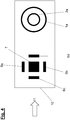
- Fig. 4 shows a planar arrangement of the impedance measurements on an SMD board 10, the thermal impedance being measured on the left and the electrical impedance being measured on the right.
- the fluid loaded with adsorptive reaches the circuit board from direction 11 and passes over it, the SMD circuit board 10 and the spaces between the equipments being completely filled with adsorbent powder.
- the thermal sensor 7 on four sides enclose, the measurement of the thermal impedance is just as independent of the flow direction 11 as the measurement of the electrical impedance by means of the concentric ring electrodes 1a and 2a.
- Fig. 5 shows an integrated two-story arrangement of the impedance measurements on two SMD boards 10a and 10b, which has the advantage that the ground adsorbent powder is held firmly between the two boards, which is a very robust design.
- Fig. 6 shows an integrated arrangement as in Fig. 5 with surrounding adsorbent 12, which in this example has the shape of cylindrical pellets.
Landscapes
- Chemical & Material Sciences (AREA)
- Life Sciences & Earth Sciences (AREA)
- Physics & Mathematics (AREA)
- Health & Medical Sciences (AREA)
- Analytical Chemistry (AREA)
- General Physics & Mathematics (AREA)
- Pathology (AREA)
- Immunology (AREA)
- Engineering & Computer Science (AREA)
- Biochemistry (AREA)
- General Health & Medical Sciences (AREA)
- Combustion & Propulsion (AREA)
- Chemical Kinetics & Catalysis (AREA)
- Food Science & Technology (AREA)
- Medicinal Chemistry (AREA)
- Spectroscopy & Molecular Physics (AREA)
- Electrochemistry (AREA)
- Investigating Or Analyzing Materials By The Use Of Electric Means (AREA)
Applications Claiming Priority (1)
| Application Number | Priority Date | Filing Date | Title |
|---|---|---|---|
| DE102019120848.3A DE102019120848A1 (de) | 2019-08-01 | 2019-08-01 | Beladungsmessverfahren und Vorrichtung |
Publications (3)
| Publication Number | Publication Date |
|---|---|
| EP3771905A1 true EP3771905A1 (fr) | 2021-02-03 |
| EP3771905C0 EP3771905C0 (fr) | 2023-08-02 |
| EP3771905B1 EP3771905B1 (fr) | 2023-08-02 |
Family
ID=71452158
Family Applications (1)
| Application Number | Title | Priority Date | Filing Date |
|---|---|---|---|
| EP20183707.7A Active EP3771905B1 (fr) | 2019-08-01 | 2020-07-02 | Organe de mesure pour mesurer l'état d'adsorption et méthode de mesure correspondante |
Country Status (2)
| Country | Link |
|---|---|
| EP (1) | EP3771905B1 (fr) |
| DE (1) | DE102019120848A1 (fr) |
Cited By (6)
| Publication number | Priority date | Publication date | Assignee | Title |
|---|---|---|---|---|
| CN114813847A (zh) * | 2022-02-28 | 2022-07-29 | 浙江颀正环保科技有限公司 | 一种在位检测气相吸附床活性炭吸附饱和度的方法和装置 |
| DE102022124106A1 (de) | 2022-09-20 | 2024-03-21 | Vaillant Gmbh | Adsorbatverdünnung |
| DE102022124090A1 (de) | 2022-09-20 | 2024-03-21 | Vaillant Gmbh | Thermische Adsorberentladung |
| DE102022124103A1 (de) | 2022-09-20 | 2024-03-21 | Vaillant Gmbh | Adsorberentladung in Unterdruckkammer |
| DE102022124104A1 (de) | 2022-09-20 | 2024-03-21 | Vaillant Gmbh | Adsorberentladung durch Verdrängungsdesorption |
| DE102022124089A1 (de) | 2022-09-20 | 2024-03-21 | Vaillant Gmbh | Adsorberentladung |
Families Citing this family (1)
| Publication number | Priority date | Publication date | Assignee | Title |
|---|---|---|---|---|
| DE102021114416A1 (de) | 2021-06-04 | 2022-12-08 | Vaillant Gmbh | Leckagedetektion |
Citations (4)
| Publication number | Priority date | Publication date | Assignee | Title |
|---|---|---|---|---|
| DE1523021A1 (de) * | 1963-12-23 | 1969-09-18 | Sun Oil Co | Feuchtigkeitsanzeigevorrichtung fuer stroemende Medien |
| DE2609869A1 (de) * | 1976-03-10 | 1977-09-15 | Kurt Dipl Chem Dr Dannhaeuser | Verfahren und schaltungsanordnungen zur ermittlung des beladezustandes und durchbruchs von adsorptionsbetten |
| DE102010003710A1 (de) * | 2010-04-08 | 2011-10-13 | Endress + Hauser Gmbh + Co. Kg | Verfahren und Vorrichtung zur Bestimmung eines in einem Adsorbermaterial enthaltenen Anteils eines adsorbierten Stoffes |
| DE102017126952A1 (de) * | 2017-11-16 | 2019-05-16 | Vaillant Gmbh | Leckageerkennung mittels Adsorber |
Family Cites Families (4)
| Publication number | Priority date | Publication date | Assignee | Title |
|---|---|---|---|---|
| GB0500393D0 (en) * | 2005-01-10 | 2005-02-16 | Univ Warwick | Microheaters |
| JP6606070B2 (ja) * | 2013-10-23 | 2019-11-13 | ザ ガバニング カウンシル オブ ザ ユニバーシティ オブ トロント | プリントデジタルマイクロ流体装置、その使用方法および製造方法 |
| EP3315956A1 (fr) * | 2016-10-31 | 2018-05-02 | Sensirion AG | Capteur à paramètres multiples avec structure de pont |
| US10598621B2 (en) * | 2017-04-11 | 2020-03-24 | Invensense, Inc. | Gas sensing device with chemical and thermal conductivity sensing |
-
2019
- 2019-08-01 DE DE102019120848.3A patent/DE102019120848A1/de not_active Withdrawn
-
2020
- 2020-07-02 EP EP20183707.7A patent/EP3771905B1/fr active Active
Patent Citations (4)
| Publication number | Priority date | Publication date | Assignee | Title |
|---|---|---|---|---|
| DE1523021A1 (de) * | 1963-12-23 | 1969-09-18 | Sun Oil Co | Feuchtigkeitsanzeigevorrichtung fuer stroemende Medien |
| DE2609869A1 (de) * | 1976-03-10 | 1977-09-15 | Kurt Dipl Chem Dr Dannhaeuser | Verfahren und schaltungsanordnungen zur ermittlung des beladezustandes und durchbruchs von adsorptionsbetten |
| DE102010003710A1 (de) * | 2010-04-08 | 2011-10-13 | Endress + Hauser Gmbh + Co. Kg | Verfahren und Vorrichtung zur Bestimmung eines in einem Adsorbermaterial enthaltenen Anteils eines adsorbierten Stoffes |
| DE102017126952A1 (de) * | 2017-11-16 | 2019-05-16 | Vaillant Gmbh | Leckageerkennung mittels Adsorber |
Non-Patent Citations (4)
| Title |
|---|
| JAEGLE M ET AL: "Thermal-electrical Impedance Spectroscopy for Fluid Characterisation", PROCEDIA ENGINEERING, ELSEVIER BV, NL, vol. 168, 4 January 2017 (2017-01-04), pages 770 - 773, XP029874768, ISSN: 1877-7058, DOI: 10.1016/J.PROENG.2016.11.276 * |
| JÜRGEN U. KELLERRAINER STAUDT: "Gas Adsorption Equilibria", 2010, SPRINGER SCIENCE, pages: 289 |
| KRAFT ET AL: "Determination of Load Dependent Thermal Conductivity of Porous Adsorbents", PROCEDDINGS OF THE COMSOL CONFERENCE, 1 January 2016 (2016-01-01), pages 1 - 7, XP055720168, Retrieved from the Internet <URL:https://www.comsol.se/paper/download/356771/kraft_paper.pdf> [retrieved on 20200804] * |
| M. JAEGLE, THERMAL-ELECTRICAL IMPEDANCE SPECTROSCOPY FOR FLUID CHARACTERIZATION |
Cited By (8)
| Publication number | Priority date | Publication date | Assignee | Title |
|---|---|---|---|---|
| CN114813847A (zh) * | 2022-02-28 | 2022-07-29 | 浙江颀正环保科技有限公司 | 一种在位检测气相吸附床活性炭吸附饱和度的方法和装置 |
| DE102022124106A1 (de) | 2022-09-20 | 2024-03-21 | Vaillant Gmbh | Adsorbatverdünnung |
| DE102022124090A1 (de) | 2022-09-20 | 2024-03-21 | Vaillant Gmbh | Thermische Adsorberentladung |
| DE102022124103A1 (de) | 2022-09-20 | 2024-03-21 | Vaillant Gmbh | Adsorberentladung in Unterdruckkammer |
| DE102022124104A1 (de) | 2022-09-20 | 2024-03-21 | Vaillant Gmbh | Adsorberentladung durch Verdrängungsdesorption |
| DE102022124089A1 (de) | 2022-09-20 | 2024-03-21 | Vaillant Gmbh | Adsorberentladung |
| EP4342569A1 (fr) | 2022-09-20 | 2024-03-27 | Vaillant GmbH | Dilution d'adsorbat |
| EP4349476A2 (fr) | 2022-09-20 | 2024-04-10 | Vaillant GmbH | Régénération d'un adsorbant par un procédé de désorption par déplacement |
Also Published As
| Publication number | Publication date |
|---|---|
| EP3771905C0 (fr) | 2023-08-02 |
| EP3771905B1 (fr) | 2023-08-02 |
| DE102019120848A1 (de) | 2021-02-04 |
Similar Documents
| Publication | Publication Date | Title |
|---|---|---|
| EP3771905B1 (fr) | Organe de mesure pour mesurer l'état d'adsorption et méthode de mesure correspondante | |
| DE102019121456A1 (de) | Beladungsmessverfahren und Vorrichtung | |
| EP2746756A2 (fr) | Dispositif de capteur destiné à déterminer les propriétés d'un liquide | |
| DE102013203437B4 (de) | Anordnung zur Bestimmung der Phasenverteilung in mehrphasigen Medien mit mindestens einer hochleitfähigen Phase und zugehöriges Verfahren | |
| EP2010896A1 (fr) | Dispositif pour la mesure bidimensionnelle de différents composants dans une section transversale d'un écoulement multiphase | |
| CH465275A (de) | Verfahren und vorrichtung zur qualitativen oder quantitativen Bestimmung einer Mischungskomponente eines Gasgemisches | |
| DE10256064B4 (de) | Verfahren und Vorrichtung zur Bestimmung des Wassergehalts und der Leitfähigkeit in Böden und Schüttgütern | |
| DE102017100264A1 (de) | Vorrichtung und Verfahren zur in situ Kalibrierung eines Thermometers | |
| WO2012168032A1 (fr) | Procédé à impédance et système pour déterminer la composition d'un mélange multiphase | |
| DE102007029908A1 (de) | Vorrichtung und Verfahren zur Masse- und/oder Feuchtemessung von dielektrischen Objekten | |
| DE19644290C2 (de) | Sensorelement zur gleichzeitigen Messung von zwei verschiedenen Eigenschaften einer chemisch sensitiven Substanz in einem Fluid | |
| EP0340509A2 (fr) | Procédé et dispositif de détermination des proportions des composants d'un mélange | |
| DE69808553T2 (de) | Gassensor mit mehreren freigelegten aktiven Elementen | |
| EP0692719B1 (fr) | Dispositif pour le mélange de fluides dans un dispositif de mesure RMN à haute pression | |
| DE69607693T2 (de) | Verfahren und Anordnung zum Abtasten der Qualitätsänderungen eines Harzbettes | |
| DE102019209199A1 (de) | Messinstrument für Eigenschaften eines strömenden Mediums | |
| DE69722926T2 (de) | Vorrichtung und verfahren zur feststellung eines fluids | |
| DE19828093C2 (de) | Einrichtung zum Messen physikalischer Größen von ein- oder mehrkomponentigen Flüssigkeiten | |
| DE202017000412U1 (de) | Filter für einen Leiter umfassend einen Spulenkörper | |
| EP3301436B1 (fr) | Appareil de mesure de conductivité destiné à mesurer une conductivité électrique d'un milieu liquide | |
| EP0281780B1 (fr) | Procédé et appareil de détermination de la composition volumétrique d'un flux de plusieurs composants | |
| EP0872727A1 (fr) | Dispositif et procédé de mesure en ligne de l'humidité dans des produits en vrac | |
| DE2740254C3 (de) | Verfahren und Anordnung zum Polarisieren von piezoelektrischen keramischen Elementen | |
| DE102005009246A1 (de) | Gasabhängige Signalgewinnung von halbleitenden Metalloxid-Gassensoren | |
| DE102019007455A1 (de) | Verfahren und Vorrichtung zur Schichtdickenmessung an dreidimensionalen technischen Objekten |
Legal Events
| Date | Code | Title | Description |
|---|---|---|---|
| PUAI | Public reference made under article 153(3) epc to a published international application that has entered the european phase |
Free format text: ORIGINAL CODE: 0009012 |
|
| STAA | Information on the status of an ep patent application or granted ep patent |
Free format text: STATUS: THE APPLICATION HAS BEEN PUBLISHED |
|
| AK | Designated contracting states |
Kind code of ref document: A1 Designated state(s): AL AT BE BG CH CY CZ DE DK EE ES FI FR GB GR HR HU IE IS IT LI LT LU LV MC MK MT NL NO PL PT RO RS SE SI SK SM TR |
|
| AX | Request for extension of the european patent |
Extension state: BA ME |
|
| STAA | Information on the status of an ep patent application or granted ep patent |
Free format text: STATUS: REQUEST FOR EXAMINATION WAS MADE |
|
| 17P | Request for examination filed |
Effective date: 20210803 |
|
| RBV | Designated contracting states (corrected) |
Designated state(s): AL AT BE BG CH CY CZ DE DK EE ES FI FR GB GR HR HU IE IS IT LI LT LU LV MC MK MT NL NO PL PT RO RS SE SI SK SM TR |
|
| GRAP | Despatch of communication of intention to grant a patent |
Free format text: ORIGINAL CODE: EPIDOSNIGR1 |
|
| STAA | Information on the status of an ep patent application or granted ep patent |
Free format text: STATUS: GRANT OF PATENT IS INTENDED |
|
| INTG | Intention to grant announced |
Effective date: 20230119 |
|
| GRAS | Grant fee paid |
Free format text: ORIGINAL CODE: EPIDOSNIGR3 |
|
| GRAA | (expected) grant |
Free format text: ORIGINAL CODE: 0009210 |
|
| STAA | Information on the status of an ep patent application or granted ep patent |
Free format text: STATUS: THE PATENT HAS BEEN GRANTED |
|
| AK | Designated contracting states |
Kind code of ref document: B1 Designated state(s): AL AT BE BG CH CY CZ DE DK EE ES FI FR GB GR HR HU IE IS IT LI LT LU LV MC MK MT NL NO PL PT RO RS SE SI SK SM TR |
|
| REG | Reference to a national code |
Ref country code: GB Ref legal event code: FG4D Free format text: NOT ENGLISH |
|
| REG | Reference to a national code |
Ref country code: CH Ref legal event code: EP |
|
| REG | Reference to a national code |
Ref country code: DE Ref legal event code: R096 Ref document number: 502020004452 Country of ref document: DE |
|
| REG | Reference to a national code |
Ref country code: IE Ref legal event code: FG4D Free format text: LANGUAGE OF EP DOCUMENT: GERMAN |
|
| U01 | Request for unitary effect filed |
Effective date: 20230802 |
|
| U07 | Unitary effect registered |
Designated state(s): AT BE BG DE DK EE FI FR IT LT LU LV MT NL PT SE SI Effective date: 20230821 |
|
| PG25 | Lapsed in a contracting state [announced via postgrant information from national office to epo] |
Ref country code: GR Free format text: LAPSE BECAUSE OF FAILURE TO SUBMIT A TRANSLATION OF THE DESCRIPTION OR TO PAY THE FEE WITHIN THE PRESCRIBED TIME-LIMIT Effective date: 20231103 |
|
| PG25 | Lapsed in a contracting state [announced via postgrant information from national office to epo] |
Ref country code: IS Free format text: LAPSE BECAUSE OF FAILURE TO SUBMIT A TRANSLATION OF THE DESCRIPTION OR TO PAY THE FEE WITHIN THE PRESCRIBED TIME-LIMIT Effective date: 20231202 |
|
| PG25 | Lapsed in a contracting state [announced via postgrant information from national office to epo] |
Ref country code: RS Free format text: LAPSE BECAUSE OF FAILURE TO SUBMIT A TRANSLATION OF THE DESCRIPTION OR TO PAY THE FEE WITHIN THE PRESCRIBED TIME-LIMIT Effective date: 20230802 Ref country code: NO Free format text: LAPSE BECAUSE OF FAILURE TO SUBMIT A TRANSLATION OF THE DESCRIPTION OR TO PAY THE FEE WITHIN THE PRESCRIBED TIME-LIMIT Effective date: 20231102 Ref country code: IS Free format text: LAPSE BECAUSE OF FAILURE TO SUBMIT A TRANSLATION OF THE DESCRIPTION OR TO PAY THE FEE WITHIN THE PRESCRIBED TIME-LIMIT Effective date: 20231202 Ref country code: HR Free format text: LAPSE BECAUSE OF FAILURE TO SUBMIT A TRANSLATION OF THE DESCRIPTION OR TO PAY THE FEE WITHIN THE PRESCRIBED TIME-LIMIT Effective date: 20230802 Ref country code: GR Free format text: LAPSE BECAUSE OF FAILURE TO SUBMIT A TRANSLATION OF THE DESCRIPTION OR TO PAY THE FEE WITHIN THE PRESCRIBED TIME-LIMIT Effective date: 20231103 |
|
| PG25 | Lapsed in a contracting state [announced via postgrant information from national office to epo] |
Ref country code: PL Free format text: LAPSE BECAUSE OF FAILURE TO SUBMIT A TRANSLATION OF THE DESCRIPTION OR TO PAY THE FEE WITHIN THE PRESCRIBED TIME-LIMIT Effective date: 20230802 |
|
| PG25 | Lapsed in a contracting state [announced via postgrant information from national office to epo] |
Ref country code: ES Free format text: LAPSE BECAUSE OF FAILURE TO SUBMIT A TRANSLATION OF THE DESCRIPTION OR TO PAY THE FEE WITHIN THE PRESCRIBED TIME-LIMIT Effective date: 20230802 |
|
| PG25 | Lapsed in a contracting state [announced via postgrant information from national office to epo] |
Ref country code: SM Free format text: LAPSE BECAUSE OF FAILURE TO SUBMIT A TRANSLATION OF THE DESCRIPTION OR TO PAY THE FEE WITHIN THE PRESCRIBED TIME-LIMIT Effective date: 20230802 Ref country code: RO Free format text: LAPSE BECAUSE OF FAILURE TO SUBMIT A TRANSLATION OF THE DESCRIPTION OR TO PAY THE FEE WITHIN THE PRESCRIBED TIME-LIMIT Effective date: 20230802 Ref country code: ES Free format text: LAPSE BECAUSE OF FAILURE TO SUBMIT A TRANSLATION OF THE DESCRIPTION OR TO PAY THE FEE WITHIN THE PRESCRIBED TIME-LIMIT Effective date: 20230802 Ref country code: CZ Free format text: LAPSE BECAUSE OF FAILURE TO SUBMIT A TRANSLATION OF THE DESCRIPTION OR TO PAY THE FEE WITHIN THE PRESCRIBED TIME-LIMIT Effective date: 20230802 Ref country code: SK Free format text: LAPSE BECAUSE OF FAILURE TO SUBMIT A TRANSLATION OF THE DESCRIPTION OR TO PAY THE FEE WITHIN THE PRESCRIBED TIME-LIMIT Effective date: 20230802 |
|
| REG | Reference to a national code |
Ref country code: DE Ref legal event code: R097 Ref document number: 502020004452 Country of ref document: DE |
|
| PLBE | No opposition filed within time limit |
Free format text: ORIGINAL CODE: 0009261 |
|
| STAA | Information on the status of an ep patent application or granted ep patent |
Free format text: STATUS: NO OPPOSITION FILED WITHIN TIME LIMIT |
|
| PGFP | Annual fee paid to national office [announced via postgrant information from national office to epo] |
Ref country code: GB Payment date: 20240626 Year of fee payment: 5 |
|
| 26N | No opposition filed |
Effective date: 20240503 |
|
| U20 | Renewal fee for the european patent with unitary effect paid |
Year of fee payment: 5 Effective date: 20240627 |
|
| PG25 | Lapsed in a contracting state [announced via postgrant information from national office to epo] |
Ref country code: MC Free format text: LAPSE BECAUSE OF FAILURE TO SUBMIT A TRANSLATION OF THE DESCRIPTION OR TO PAY THE FEE WITHIN THE PRESCRIBED TIME-LIMIT Effective date: 20230802 |
|
| REG | Reference to a national code |
Ref country code: CH Ref legal event code: PL |
|
| PG25 | Lapsed in a contracting state [announced via postgrant information from national office to epo] |
Ref country code: CH Free format text: LAPSE BECAUSE OF NON-PAYMENT OF DUE FEES Effective date: 20240731 |
|
| PG25 | Lapsed in a contracting state [announced via postgrant information from national office to epo] |
Ref country code: IE Free format text: LAPSE BECAUSE OF NON-PAYMENT OF DUE FEES Effective date: 20240702 |
|
| U20 | Renewal fee for the european patent with unitary effect paid |
Year of fee payment: 6 Effective date: 20250626 |
|
| PG25 | Lapsed in a contracting state [announced via postgrant information from national office to epo] |
Ref country code: CY Free format text: LAPSE BECAUSE OF FAILURE TO SUBMIT A TRANSLATION OF THE DESCRIPTION OR TO PAY THE FEE WITHIN THE PRESCRIBED TIME-LIMIT; INVALID AB INITIO Effective date: 20200702 |
|
| PG25 | Lapsed in a contracting state [announced via postgrant information from national office to epo] |
Ref country code: HU Free format text: LAPSE BECAUSE OF FAILURE TO SUBMIT A TRANSLATION OF THE DESCRIPTION OR TO PAY THE FEE WITHIN THE PRESCRIBED TIME-LIMIT; INVALID AB INITIO Effective date: 20200702 |
|
| GBPC | Gb: european patent ceased through non-payment of renewal fee |
Effective date: 20250702 |
|
| PG25 | Lapsed in a contracting state [announced via postgrant information from national office to epo] |
Ref country code: GB Free format text: LAPSE BECAUSE OF NON-PAYMENT OF DUE FEES Effective date: 20250702 |