EP3772387A2 - Scie à fil pourvu d'éléments de coupe pourvu de tranchant en biais géométrique et procédé de fabrication de la scie à fil - Google Patents
Scie à fil pourvu d'éléments de coupe pourvu de tranchant en biais géométrique et procédé de fabrication de la scie à fil Download PDFInfo
- Publication number
- EP3772387A2 EP3772387A2 EP20187740.4A EP20187740A EP3772387A2 EP 3772387 A2 EP3772387 A2 EP 3772387A2 EP 20187740 A EP20187740 A EP 20187740A EP 3772387 A2 EP3772387 A2 EP 3772387A2
- Authority
- EP
- European Patent Office
- Prior art keywords
- saw
- base body
- cutting
- wire
- elements
- Prior art date
- Legal status (The legal status is an assumption and is not a legal conclusion. Google has not performed a legal analysis and makes no representation as to the accuracy of the status listed.)
- Pending
Links
Images
Classifications
-
- B—PERFORMING OPERATIONS; TRANSPORTING
- B28—WORKING CEMENT, CLAY, OR STONE
- B28D—WORKING STONE OR STONE-LIKE MATERIALS
- B28D1/00—Working stone or stone-like materials, e.g. brick, concrete or glass, not provided for elsewhere; Machines, devices, tools therefor
- B28D1/02—Working stone or stone-like materials, e.g. brick, concrete or glass, not provided for elsewhere; Machines, devices, tools therefor by sawing
- B28D1/12—Saw-blades or saw-discs specially adapted for working stone
- B28D1/124—Saw chains; rod-like saw blades; saw cables
-
- B—PERFORMING OPERATIONS; TRANSPORTING
- B23—MACHINE TOOLS; METAL-WORKING NOT OTHERWISE PROVIDED FOR
- B23D—PLANING; SLOTTING; SHEARING; BROACHING; SAWING; FILING; SCRAPING; LIKE OPERATIONS FOR WORKING METAL BY REMOVING MATERIAL, NOT OTHERWISE PROVIDED FOR
- B23D61/00—Tools for sawing machines or sawing devices; Clamping devices for these tools
- B23D61/18—Sawing tools of special type, e.g. wire saw strands, saw blades or saw wire equipped with diamonds or other abrasive particles in selected individual positions
- B23D61/185—Saw wires; Saw cables; Twisted saw strips
Definitions
- the invention relates to a wire saw with a saw wire on which a plurality of cutting elements are arranged at intervals from one another, which have an annular base body on which at least one geometrically determined cutting edge is formed.
- Cutting elements are often also referred to as cutting beads, which are either designed as individual parts or these in turn have a carrier body with at least one cutting element.
- Wire saws are used for sawing natural stone or concrete, for example, and these have a sawing cable as a basic component, in particular a steel cable, and on the sawing cable are at regular intervals from one another Arranged cutting elements that can be brought into contact with the workpiece to be sawed.
- the cutting elements are drawn through the kerf, and the cutting elements have abrasive sections with, as a rule, geometrically undefined cutting edges.
- These cutting elements with an indefinite cutting edge are mostly made of a sintered material, and hard materials, for example polycrystalline diamond or grains of cubic drill nitrite, are located in a composite matrix.
- the abrasive surfaces are usually located on the outer surface of the essentially cylindrical cutting elements, and a feed force of the saw cable in the cutting direction brings the abrasive surfaces into contact with the workpiece in order to reduce the sawing effect due to the abrasion of the cutting elements with the material of the To achieve workpiece.
- the DE 40 38 480 A1 , the CN 206084004 U , the EP 0 486 238 A2 and the KR 100583474 B1 in each case exemplary embodiments of wire saws with a saw wire on which several cutting elements are arranged at intervals from one another, which either per se or in the form of inserts have abrasive inserts or sections with a geometrically indefinite cutting edge.
- More recent forms of wire saws have a saw wire on which several cutting elements are arranged at intervals from one another, which have an annular base body on which at least one geometrically defined cutting edge is formed.
- the ring-shaped base body is received on a carrier body which in turn is attached to the saw cable.
- the DE 10 2015 109 432 B3 a wire saw with a saw wire and a number of cutting elements that have a geometrically determined cutting edge.
- the cutting elements are applied to carrier bodies, and the carrier bodies are in turn attached to the outer circumference of the saw cable.
- the cutting elements have on the front in the direction of movement of the saw cable a circumferential, geometrically determined cutting edge in the form of a cutting edge circumferentially delimiting a front surface, an area with a geometrically undefined cutting edge also being formed on the outer circumference of the support body.
- the cutting elements can be formed from diamond, for example polycrystalline diamond or monocrystalline diamond. It is stated here that the diamond can be sintered onto a suitable base, which forms a carrier material or a carrier body, so that the diamond is sintered onto a hard metal base, for example. This ring-shaped cutting element formed in this way is then joined to a base area of the carrier body, for example by means of gluing, welding, soldering or pressing.
- the object of the invention thus arises from the prior art to overcome the disadvantages listed above and in particular to propose a simple structure of a saw wire in which the cutting elements can be easily produced and applied to the saw wire, but with sufficient accuracy on the Saw wire can be positioned to be formed with a geometrically defined cutting edge.
- the invention includes the technical teaching that a central through opening is provided in the annular base body of the cutting element, via which the base body is received directly on the outer circumference of the saw cable.
- the core idea of the invention is the provision of a cutting element made of a correspondingly hard material, and the cutting element with its base body is received directly on the saw wire, free of further holding elements. This has the advantage of a simple one Construction of the saw wire without the use of carriers on which the cutting elements have to be applied separately.
- the through opening in the base body is advantageously formed with an inside diameter which is adapted to the outside diameter of the saw cable so that the base body is held on the outside circumference of the saw cable.
- the saw cable is not a longitudinal body with a smooth outer circumferential surface and, in particular with a steel cable, topographies can predominate on the outer circumference which enable the cutting element to be applied in contact with a partial gap.
- the through opening of the saw wire can be designed with an inner diameter which is 1% to 20% and / or 5% to 15% and / or 10% larger than the outer diameter of the saw wire.
- a bonding compound is injected into an annular gap formed between the inner diameter of the through opening and the outer diameter of the saw cord after the cutting element has been applied to the saw cord.
- a bonding compound for example a plastic, can be injected into the annular gap in the injection molding process, so that the diameter difference between the inner diameter and the outer diameter is advantageous for forming the annular gap.
- cutting elements according to the invention can be secured on the saw cable in such a way that they do not leave their required position even when they are in engagement with the workpiece and the geometrically determined cutting edge properly comes into contact with the workpiece.
- the cutting elements are thus in the cutting direction of the saw wire and also in Fixed in the circumferential direction, in particular immovable and thus well aligned on the saw wire.
- Sleeve elements or springs can be arranged between the cutting elements.
- the springs or sleeve elements surround the saw cord. This avoids damage to the saw cord through direct contact of the saw cord with the workpiece.
- the base body for the exclusive formation of the cutting element advantageously has a base body and a cutting body, and the base body and the cutting body form the base body in one piece.
- the cutting body can lie in front of the base body in the cutting direction and have a smaller thickness than the base body.
- the base body has a hardness of at least 1500 HV and / or the cutting body has a hardness of at least 4500 HV. It has proven to be advantageous if the base body has a tungsten carbide sintered material and / or if the cutting body has a polycrystalline diamond.
- the base body and the cutting body can be produced in a common sintering process in order to avoid a separate joining step between the two bodies.
- the method for producing the cutting element can furthermore provide that the base body and the cutting body are sintered together at a temperature of 1,200 ° C. to 1,400 ° C. and / or at a pressure of approximately or more than 4 GPa.
- the annular base body of the cutting element has a conical outer circumferential surface, and the cone angle of conical outer circumferential surface to the central axis in particular has a value of 1 ° to 12 °.
- the base body for forming the cutting element has the shape of a truncated cone with an essentially flat front and back, the base body having the cutting body made of, for example, polycrystalline diamond in the area of the larger diameter of the truncated cone and in the rear
- the base body has the base body, which is formed, for example, from a tungsten carbide sintered material and thus forms the support body for the actual cutting body.
- the frustoconical base body can have a planar front surface and a planar rear surface, the front surface merging into the conical outer circumferential surface to form the cutting edge, which is in particular configured in an annular manner.
- the base body has a front surface which co-determines the geometrically determined cutting edge, in which a particularly encircling bevel is introduced adjacent to the cutting edge.
- the bevel can have a bevel angle that results between the surface of the bevel and the front surface and has a value of 0.1 ° to 25 °.
- the invention is also directed to a method for producing a wire saw with a saw wire on which a plurality of cutting elements are arranged at a distance from one another, which form an annular base body have, on which at least one geometrically defined cutting edge is formed.
- the method has at least the following steps: providing the cutting elements with an annular base body with a central through opening and arranging the cutting elements directly on the saw cable so that the cutting elements are held on the saw cable.
- the direct arrangement of the cutting element on the saw cable is to be understood in the present sense that the arrangement takes place without the aid of further holding elements, and the cutting element, for example having a base body and a cutting body as a one-piece sintered body, is located with the respective materials, in particular tungsten -Carbide sintered material and polycrystalline or monocrystalline diamond, in direct contact with the saw cord, which is in particular formed by a steel cord.
- saw cables can be produced in a simple manner, but they have a geometrically defined cutting edge and thus enable lower cutting speeds and higher metal removal rates and higher feed rates, but without using holding elements made of hard metal, for example.
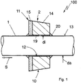
- Figure 1 shows an embodiment of a wire saw 100 for sawing, for example, stone, concrete or other materials, for use in the natural stone industry, for the dismantling of concrete buildings and the like, but also for sawing, for example, metallic components, for example for cutting up discarded aircraft fuselages and the like.
- the wire saw 100 has a saw wire 1, which is designed in the form of a ring in particular with a closure element and can be driven in a cutting direction S via a drive wheel.
- cutting elements 2 in the form of cutting beads are positioned on the saw cable 1.
- the cutting elements 2 can also simply be arranged on the saw cord 1 at defined intervals.
- the embodiment of the wire saw 100 according to the invention has cutting elements 2 with a base body 10 on which a geometrically determined cutting edge 11 is formed.
- This annular base body 10 has a central through opening 12, via which the base body 10 is directly received on the outer circumference 13 of the saw cord 1.
- the inner diameter di of the through opening 12 is larger than the outer diameter d a of the saw cord 1.
- the annular gap 19 formed in between is filled with a connecting compound 20, which is formed, for example, by a plastic material that is injected into the annular gap with an injection molding process 19 is injected. It is thereby achieved that the base body 10, on which the cutting edge 11 is formed directly, is arranged directly on the saw cord 1, to be precise without the aid of further holding elements.
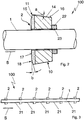
- Figure 2 shows a modified embodiment of the wire saw 100 with the saw wire 1 and with the cutting element 2 from the base body 10, consisting of the base body 14 and the cutting body 15.
- the geometrically determined cutting edge 11 is beginning on a front surface 17 in the transition to the outer peripheral surface 16 is formed, and the front surface 17 has a bevel 18 adjacent to the cutting edge 11.
- the front face 17 is designed as a rake face and the outer circumferential face 16 is designed as a free face.
- a bevel angle b of the bevel 18 with a value of 0.1 ° to 25 ° is formed, the bevel angle b being plotted between the front surface 17 and the surface of the bevel 18.
- the conical outer circumferential surface has a cone angle a with a value of, for example, 1 ° to 12 °.
- the bevel 18 forms a negative cutting angle of the cutting edge 11, so that the cutting element 2 on the saw cable 1 is particularly suitable for cutting mineral materials, in particular natural stone or concrete.
- a retaining ring 22 which can be designed in particular with an inner surface 23 having a thread. Via the thread in the inner surface 23, the retaining ring 22 can be brought out in a fixed position on the saw cable 1, in particular by additional soldering or by material connection, but also, for example, with an injected plastic compound. As a result, the retaining ring 22 forms a support effect for the base body 10, so that it does not inadvertently change its position in the cutting direction S on the saw cable 1.
- the illustrated cutting element 2 is produced from a one-piece base body 10 formed free of joining processes, and the base body 14 has, for example, a tungsten carbide sintered material and the cutting body 15 has, for example, a polycrystalline diamond (PCD) or a monocrystalline diamond ( MKD) as a material.
- the length of the entire base body 10 is, for example, 2 mm to 25 mm, preferably 10 mm, and the diameter in the region of the cutting edge 11 of the base body 10 is, for example, 7 mm to 12 mm, preferably 11 mm.
- the saw cable 1 has, for example, a diameter of 1 mm to 15 mm, preferably of 5 mm, and the inner diameter di of the through opening 12 has a value of, for example 5.5 mm.
- the internal diameter d i is thus approximately 10% larger than the external diameter da of the saw wire 1, for example.
- the thickness of the base body 10 in the cutting direction S is particularly advantageously only about 1 mm.
- the remaining 9 mm form a high-strength base body 14 which serves as a support body for the actual cutting body 15.
- the base body 10 consists essentially of the base body 14 and the cutting body 15 is applied to the front, active surface of the base body 14 by a deposition process, for example by sputtering.
- FIG. 3 shows a view of the wire saw 100 with a saw wire 1 and with several cutting elements 2.
- the view shows once again that the cutting elements 2 have a truncated cone shape and are deployed in such a way that they point in the cutting direction S with a larger diameter.
- Sleeve elements 21 are located between the cutting elements 2 so that the saw cord 1 does not come into direct contact with the workpiece.
Landscapes
- Engineering & Computer Science (AREA)
- Mechanical Engineering (AREA)
- Mining & Mineral Resources (AREA)
- Processing Of Stones Or Stones Resemblance Materials (AREA)
- Finish Polishing, Edge Sharpening, And Grinding By Specific Grinding Devices (AREA)
- Polishing Bodies And Polishing Tools (AREA)
Applications Claiming Priority (1)
| Application Number | Priority Date | Filing Date | Title |
|---|---|---|---|
| DE102019121435.1A DE102019121435A1 (de) | 2019-08-08 | 2019-08-08 | Seilsäge mit Schneidelementen mit geometrisch bestimmter Schneide und Verfahren zur Herstellung der Seilsäge |
Publications (2)
| Publication Number | Publication Date |
|---|---|
| EP3772387A2 true EP3772387A2 (fr) | 2021-02-10 |
| EP3772387A3 EP3772387A3 (fr) | 2021-05-19 |
Family
ID=71786862
Family Applications (1)
| Application Number | Title | Priority Date | Filing Date |
|---|---|---|---|
| EP20187740.4A Pending EP3772387A3 (fr) | 2019-08-08 | 2020-07-24 | Scie à fil pourvu d'éléments de coupe pourvu de tranchant en biais géométrique et procédé de fabrication de la scie à fil |
Country Status (2)
| Country | Link |
|---|---|
| EP (1) | EP3772387A3 (fr) |
| DE (1) | DE102019121435A1 (fr) |
Cited By (1)
| Publication number | Priority date | Publication date | Assignee | Title |
|---|---|---|---|---|
| CN117445196A (zh) * | 2023-09-19 | 2024-01-26 | 桂林创巨华材料科技有限公司 | 一种多边形绳锯串珠等形磨耗结构及加工方法 |
Families Citing this family (1)
| Publication number | Priority date | Publication date | Assignee | Title |
|---|---|---|---|---|
| IT202200024282A1 (it) | 2022-11-25 | 2024-05-25 | Jfd Marble & Granit S R L | Corpo di rinforzo per fili diamantati e filo diamantato che utilizza uno o piu’ di detti corpi di rinforzo |
Citations (5)
| Publication number | Priority date | Publication date | Assignee | Title |
|---|---|---|---|---|
| EP0486238A2 (fr) | 1990-11-16 | 1992-05-20 | Unicorn Abrasives Limited | Scies à fil |
| DE4038480A1 (de) | 1990-12-03 | 1992-06-04 | Falkenstein J Masch Verzahnung | Saegeseil |
| KR100583474B1 (ko) | 2004-12-20 | 2006-05-26 | 이화다이아몬드공업 주식회사 | 와이어 쏘우용 비드 및 와이어 쏘우 |
| DE102015109432B3 (de) | 2015-06-12 | 2016-12-08 | Universität Kassel | Schneidperle für ein Sägeseil, Sägeseil und Verfahren zur Herstellung eines Sägeseils |
| CN206084004U (zh) | 2016-09-14 | 2017-04-12 | 江西众利超硬材料工具有限公司 | 改进型超硬材料绳锯 |
Family Cites Families (10)
| Publication number | Priority date | Publication date | Assignee | Title |
|---|---|---|---|---|
| US3884212A (en) * | 1973-11-01 | 1975-05-20 | Meyers W F Co | Wire saw |
| DE2400205A1 (de) * | 1974-01-03 | 1975-07-17 | Eiselt Guenter | Werkzeug zum zertrennen von poroesen und/oder spezifisch leichten materialien |
| IT1236762B (it) * | 1988-10-28 | 1993-04-02 | Fune elicoidale con tagliente di diamante. | |
| GB2243094A (en) * | 1990-04-17 | 1991-10-23 | Neil George Reid | Wire saws |
| KR100216779B1 (ko) * | 1997-04-11 | 1999-09-01 | 김세광 | 와이어 쏘 |
| DE19802938A1 (de) * | 1998-01-27 | 1999-07-29 | Buediam Diamantwerkzeuge R Und | Sägeseil mit Sägeperle |
| FR2819442B1 (fr) * | 2001-01-15 | 2003-05-30 | Cofilt | Outil de coupe souple |
| US7866418B2 (en) * | 2008-10-03 | 2011-01-11 | Us Synthetic Corporation | Rotary drill bit including polycrystalline diamond cutting elements |
| DE102009014520A1 (de) * | 2009-03-13 | 2010-09-23 | Dr. Fritsch Sondermaschinen Gmbh | Schneidperlen-Sägeseil, insbesondere Diamantperlen-Sägeseil, sowie Verfahren zur Herstellung von Schneidperlen |
| DE102010021959A1 (de) * | 2010-05-28 | 2011-12-01 | Mafell Ag | Sägeseil |
-
2019
- 2019-08-08 DE DE102019121435.1A patent/DE102019121435A1/de active Pending
-
2020
- 2020-07-24 EP EP20187740.4A patent/EP3772387A3/fr active Pending
Patent Citations (5)
| Publication number | Priority date | Publication date | Assignee | Title |
|---|---|---|---|---|
| EP0486238A2 (fr) | 1990-11-16 | 1992-05-20 | Unicorn Abrasives Limited | Scies à fil |
| DE4038480A1 (de) | 1990-12-03 | 1992-06-04 | Falkenstein J Masch Verzahnung | Saegeseil |
| KR100583474B1 (ko) | 2004-12-20 | 2006-05-26 | 이화다이아몬드공업 주식회사 | 와이어 쏘우용 비드 및 와이어 쏘우 |
| DE102015109432B3 (de) | 2015-06-12 | 2016-12-08 | Universität Kassel | Schneidperle für ein Sägeseil, Sägeseil und Verfahren zur Herstellung eines Sägeseils |
| CN206084004U (zh) | 2016-09-14 | 2017-04-12 | 江西众利超硬材料工具有限公司 | 改进型超硬材料绳锯 |
Cited By (1)
| Publication number | Priority date | Publication date | Assignee | Title |
|---|---|---|---|---|
| CN117445196A (zh) * | 2023-09-19 | 2024-01-26 | 桂林创巨华材料科技有限公司 | 一种多边形绳锯串珠等形磨耗结构及加工方法 |
Also Published As
| Publication number | Publication date |
|---|---|
| EP3772387A3 (fr) | 2021-05-19 |
| DE102019121435A1 (de) | 2021-02-11 |
Similar Documents
| Publication | Publication Date | Title |
|---|---|---|
| DE60004354T2 (de) | Aus superhartem material hergestellter gegenstand | |
| EP0104458A2 (fr) | Tamis pour centrifuge et procédé de fabrication dudit tamis | |
| DE69302776T2 (de) | Verbundbauschneidwerkzeuge | |
| EP2253402B1 (fr) | Foret | |
| EP1602445A2 (fr) | Procédé, outil et machine d'usinage pour la fabrication d'éléments de prothèse dentaire | |
| EP1042086B2 (fr) | Procede de production d'un outil de percage pour machines-outils | |
| EP3137254B1 (fr) | Outil | |
| DE102007044269A1 (de) | Nur teilweise geschliffener Werkzeugstab aus Sintermaterial | |
| DE102019121435A1 (de) | Seilsäge mit Schneidelementen mit geometrisch bestimmter Schneide und Verfahren zur Herstellung der Seilsäge | |
| WO1988000513A1 (fr) | Procede et dispositif de fabrication de pieces tournees coupees dans des barres | |
| EP3638451A1 (fr) | Élément de serrage destiné à positionner et/ou à fixer une pièce ou un outil | |
| WO2019052850A1 (fr) | Outil de rugosification et procédé de fabrication associé | |
| EP1784282B1 (fr) | Meule pour produire des filetages a billes males ou femelles sur des pieces a usiner | |
| DE102018007711A1 (de) | Herstellungsverfahren für Tiefbohrwerkzeuge | |
| EP3592492B1 (fr) | Outil destiné à tailler en développante ou à dresser un outil de finition comprenant une denture extérieure | |
| DE102004040844A1 (de) | Schneidplatte aus PCBN oder einem CBN-Verbundwerkstoff mit Spannmulde | |
| EP2809469B1 (fr) | Plaquette de coupe | |
| WO1982002012A1 (fr) | Outil combine | |
| DE102008061255A1 (de) | Verfahren zur Herstellung von Verfahren zur Herstellung von Teilen mit wenigstens einer gekrümmten Fläche, umfassend eine Vielzahl von Hohlkörpern mit dünnen Wänden | |
| EP3307467B1 (fr) | Perle de coupe pour un câble de sciage | |
| EP0487539A1 (fr) | Cylindre de coupe ou cylindre d'estampage et procede pour leur fabrication. | |
| AT517140A1 (de) | Schleifwerkzeug | |
| EP4288247A1 (fr) | Barre de polissage, procédé de fabrication d'une barre de polissage et outil de polissage | |
| DE202012100409U1 (de) | Drahtvorschubrolle | |
| WO2012150058A1 (fr) | Outil de fraisage et/ou de perçage |
Legal Events
| Date | Code | Title | Description |
|---|---|---|---|
| PUAI | Public reference made under article 153(3) epc to a published international application that has entered the european phase |
Free format text: ORIGINAL CODE: 0009012 |
|
| STAA | Information on the status of an ep patent application or granted ep patent |
Free format text: STATUS: THE APPLICATION HAS BEEN PUBLISHED |
|
| AK | Designated contracting states |
Kind code of ref document: A2 Designated state(s): AL AT BE BG CH CY CZ DE DK EE ES FI FR GB GR HR HU IE IS IT LI LT LU LV MC MK MT NL NO PL PT RO RS SE SI SK SM TR |
|
| AX | Request for extension of the european patent |
Extension state: BA ME |
|
| PUAL | Search report despatched |
Free format text: ORIGINAL CODE: 0009013 |
|
| AK | Designated contracting states |
Kind code of ref document: A3 Designated state(s): AL AT BE BG CH CY CZ DE DK EE ES FI FR GB GR HR HU IE IS IT LI LT LU LV MC MK MT NL NO PL PT RO RS SE SI SK SM TR |
|
| RIC1 | Information provided on ipc code assigned before grant |
Ipc: B23D 61/18 20060101AFI20210413BHEP Ipc: B28D 1/12 20060101ALI20210413BHEP |
|
| STAA | Information on the status of an ep patent application or granted ep patent |
Free format text: STATUS: REQUEST FOR EXAMINATION WAS MADE |
|
| 17P | Request for examination filed |
Effective date: 20210607 |
|
| RBV | Designated contracting states (corrected) |
Designated state(s): AL AT BE BG CH CY CZ DE DK EE ES FI FR GB GR HR HU IE IS IT LI LT LU LV MC MK MT NL NO PL PT RO RS SE SI SK SM TR |
|
| STAA | Information on the status of an ep patent application or granted ep patent |
Free format text: STATUS: EXAMINATION IS IN PROGRESS |
|
| 17Q | First examination report despatched |
Effective date: 20221222 |
|
| P01 | Opt-out of the competence of the unified patent court (upc) registered |
Free format text: CASE NUMBER: APP_57800/2024 Effective date: 20241022 |