EP3772968B1 - Agencement et procédé de dépouillement de parties de volaille contenant la poitrine de volaille - Google Patents
Agencement et procédé de dépouillement de parties de volaille contenant la poitrine de volaille Download PDFInfo
- Publication number
- EP3772968B1 EP3772968B1 EP18715635.1A EP18715635A EP3772968B1 EP 3772968 B1 EP3772968 B1 EP 3772968B1 EP 18715635 A EP18715635 A EP 18715635A EP 3772968 B1 EP3772968 B1 EP 3772968B1
- Authority
- EP
- European Patent Office
- Prior art keywords
- poultry
- roller
- skin
- edge
- arrangement according
- Prior art date
- Legal status (The legal status is an assumption and is not a legal conclusion. Google has not performed a legal analysis and makes no representation as to the accuracy of the status listed.)
- Active
Links
Images



Classifications
-
- A—HUMAN NECESSITIES
- A22—BUTCHERING; MEAT TREATMENT; PROCESSING POULTRY OR FISH
- A22C—PROCESSING MEAT, POULTRY, OR FISH
- A22C21/00—Processing poultry
- A22C21/0092—Skinning poultry or parts of poultry
-
- A—HUMAN NECESSITIES
- A22—BUTCHERING; MEAT TREATMENT; PROCESSING POULTRY OR FISH
- A22B—SLAUGHTERING
- A22B5/00—Accessories for use during or after slaughtering
- A22B5/16—Skinning instruments or knives
- A22B5/166—Drum skinners
-
- A—HUMAN NECESSITIES
- A22—BUTCHERING; MEAT TREATMENT; PROCESSING POULTRY OR FISH
- A22C—PROCESSING MEAT, POULTRY, OR FISH
- A22C21/00—Processing poultry
- A22C21/0053—Transferring or conveying devices for poultry
Definitions
- the present invention relates to an arrangement for skinning poultry parts containing the poultry breast, with a conveyor device which comprises saddle elements designed to convey the poultry parts in the conveying direction along a skinning device, and the skinning device comprises at least one rotatingly driven profiled roller and a guide element, wherein the roller is designed together with a feed edge of the guide element to form a feed gap for grasping the skin on the poultry breast side, wherein the guide element each comprises flank guide elements designed to guide the poultry part laterally, and wherein the flank guide elements have inner guide surfaces designed to rest on the muscle meat of the poultry part.
- the invention further relates to a method for skinning poultry parts containing the poultry breast, comprising the steps of: conveying the poultry parts in the conveying direction along a skinning device by means of saddle elements of a conveyor device, rotatingly driving at least one profiled roller, the roller together with a draw-in edge of a guide element forming a draw-in gap for grasping the skin on the poultry breast side, automatically grasping the skin by means of the draw-in gap, and guiding the poultry part laterally by means of flank guide elements by placing inner guide surfaces on the muscle meat of the poultry part.
- Such arrangements and methods are used in mechanical poultry processing. Before filleting poultry carcasses, they must be skinned. For example, to skin poultry breast caps and front halves, skinners are used in filleting machines, which pull the skin off the fillets by means of a roller and a fixed clamping shoe.
- Such skinners are, for example, from the document US 2011/092146 A1
- the above-mentioned order and the above-mentioned procedure are also contained in the document EP 3 041 361 A1 out.
- the disadvantage of the known skinners and skinning processes is that the skin is not removed reliably and completely.
- skinning poultry breast caps and front halves is difficult due to special anatomical conditions.
- the skin in the area of the respiratory fold is fused to the poultry carcass. This ensures that the skin does not come off completely and/or cannot be separated from the poultry body in a controlled manner.
- the problem of skin parts remaining on the fillets can be solved, for example, by carrying out suitable processing steps.
- the skin that has grown together with the fillet is simply separated in this way.
- an additional processing step is required and on the other hand, there is a loss of yield because the trimming cut reduces the fillet size.
- the object of the present invention to propose an arrangement which ensures complete automatic removal of the poultry skin with high reliability. Furthermore, the object is to propose a corresponding method.
- flank guide elements each comprise cutting means designed to separate the connection between the skin and the poultry part.
- the inner guide surfaces that come into contact with the muscle meat support the process of separating the skin from the poultry carcass until the skin is only connected to the poultry carcass in the area of the respiratory fold. Due to the precise guidance, the skin is only finally separated from the poultry carcass in a controlled manner after all areas of the skin have been separated from the poultry carcass.
- the guide element according to the invention with the flank guide elements is designed to additionally lift the poultry carcasses when passing the guide element in such a way that the distance to the roller increases. In this way, the tensile force already generated by the rotating roller exerts an additional force that assists in the removal of the skin. Shortly before the poultry carcass or the poultry part has completely passed the guide element according to the invention, it reaches the highest position with the greatest distance from the roller. In this position, the poultry skin is maximally pre-tensioned by the aforementioned acting forces and in the process is finally and largely completely removed from the poultry carcass.
- the guide element is preferably designed as a shaped body, for example as a hollow or solid body.
- the guide element is designed as a single piece.
- the guide element is, for example, milled from solid material or manufactured using 3D printing.
- the flank guide elements each comprise cutting means designed to separate the connection between the skin and the poultry part.
- the cutting means enable a precise and exact cutting through of the skin that has grown together with the poultry carcass in the area of the respiratory fold.
- the cutting means are therefore preferably arranged on the output side, downstream of the guide element in relation to the conveying direction.
- flank guide elements each comprise outer guide surfaces designed to guide the skin connected on the poultry part side, wherein the outer guide surfaces each extend between the intake edge and a separating edge at which the inner guide surface borders on the outer guide surface.
- the outer guide surfaces thus form additional guide surfaces for the defined guidance of the detached skin areas.
- the inner guide surfaces essentially serve to guide the poultry carcass, while the outer guide surfaces are designed and equipped to guide and direct the poultry skin.
- the outer guide surfaces are particularly designed to designed to guide the skin into the intake gap of the skinning device and at the same time to pre-tension the skin so that the skin is detached from the poultry carcass under constant tensile force and finally also precisely detached at the connection to the poultry carcass that remains until the end in the area of the respiratory fold.
- the inner guide surfaces with their separating edge are each at least essentially concavely curved. Due to the concavity of the inner guide surfaces, they nestle optimally against the fillets of the poultry carcass and thus ensure precise guidance and support of the poultry part during skinning.
- the geometry of the inner guide surfaces is also preferably adapted to the average geometry of the poultry parts to be processed.
- the inner guide surfaces can be completely concave or essentially concavely curved. Inner surface geometries with multiple concave curvatures in different spatial directions can also be used.
- the guide element comprises a contact surface arranged between the inner guide surfaces, wherein the contact surface forms a ramp inclined at an angle ⁇ relative to a roller tangential starting from the intake edge.
- the contact surface offers the advantage that the poultry part is elastically compressed and compressed to a certain extent. On the one hand, this promotes the detachment process of the skin and, on the other hand, leads to the poultry part being changed in terms of its height relative to the conveyor device, namely being raised. This leads to the skin being guided away from the roller, whereby the skin is further elastically stretched and the detachment forces increase accordingly. The detachment forces thus reach a magnitude that is sufficient to finally detach the skin that has grown together in the area of the respiratory fold.
- a further practical embodiment of the invention is characterized in that the separating edge is seamlessly connected to the contact surfaces on each side. This creates a step- and projection-free, continuous guide surface that is as smooth as possible, which on the one hand enables the poultry part to be guided with as little resistance as possible and at the same time prevents damage to the poultry fillets due to mechanical impact.
- the contact surface edge of the contact surface is arranged directly adjacent to the intake edge.
- the "threading" of the skin into the intake gap is supported by a defined intake edge and immediately after the skin is grasped, the described compression and upsetting is carried out while the poultry part is simultaneously lifted. This ensures that the guide element according to the invention slides between the skin to be removed and the remaining poultry carcass and that the skin following due to the conveying movement is guided into the intake gap.
- flank guide elements are designed in such a way that the clear width between the inner guide surfaces tapers in the conveying direction. This causes additional lateral compression on the flanks of the poultry part or the poultry carcass. At the same time, the inner guide surface rests against the muscle meat in the flank area of the poultry carcass under light pressure and thus supports the skin removal effect.
- a preferred development of the invention is characterized in that the inner guide surfaces of the flank guide elements each have an end edge, whereby the end edge of one of the inner guide surfaces is shorter than the respective section of the separating edge of the same inner guide surface.
- the separating edge which is designed to reach between the skin and the poultry carcass containing the muscle meat, defines an entry cross-section of the guide element according to the invention.
- the entry cross-section refers to the free cross-sectional area which, from the perspective of the poultry carcass, initially forms a free passage when entering the guide element.
- the end edges define the exit cross-section of the guide element according to the invention, i.e. the cross-sectional area which is available when the poultry carcass exits the effective area of the guide element.
- the selected relationship between the respective lengths of the end edges and the separating edge means that the free cross-section is constantly reduced along the passage path of the poultry in order to achieve the effects described above.
- each of the inner guide surfaces is designed as an enveloping surface which extends between the end edge and the separating edge of the respective inner guide surface.
- the enveloping surface forms a A support surface that is as smooth as possible and allows the muscle meat surfaces of the poultry part to slide over with as little resistance as possible.
- a further expedient embodiment of the invention is characterized in that the separating edge, the contact surface edges and/or the end edges are rounded.
- the rounding reduces the risk of damage to the muscle tissue that would otherwise be possible.
- the rounding of the separating edge in particular has a positive effect on the threading behavior of the skin into the feed gap.
- the muscle is reliably guided to the inner guide surfaces or the contact surface via the rounded separating edge.
- the rounding of the contact surface edges and/or the end edges ensures that the skin guided over them slides well. This reliably prevents unwanted tearing or damage to the skin, which could otherwise lead to uncontrolled tearing of the skin and have a negative effect on the removal result.
- the roller is driven by a drive unit such that the peripheral speed of the roller is greater than the conveying speed of the conveyor.
- the feed speed at which the skin is drawn into the feed gap is greater than the speed at which the poultry parts are conveyed in the conveying direction.
- the skin runs ahead of the poultry carcass. This elastically pre-tensions the skin, which further supports the detachment process.
- a further expedient embodiment of the invention is characterized in that the roller has a lateral surface profile that is inclined relative to its axis of rotation in the area of the flank guide elements.
- the lateral surface profile is thus set at an angle in the area mentioned with respect to the circumferential direction of the roller.
- the skin is therefore not only subjected to a tensile force in the circumferential direction of the roller, but also to an additional force component perpendicular to the circumferential direction or parallel to the axis of rotation of the roller. Using this transverse force component, it is possible to spread the skin as evenly as possible over the circumference of the roller and to distribute it as evenly as possible over it in order to support the overall detachment effect.
- the lateral surface profiles in the area of the flank guide elements are each inclined towards the front sides of the roller, opposite to the direction of rotation of the roller.
- the skin is thus advantageously guided outwards, namely towards the roller sides or the front sides of the roller. This can reliably counteract clogging of the intake gap by accumulating skin.
- a preferred development of the invention is characterized in that the roller has a lateral surface profile aligned parallel to the axis of rotation of the roller in the area of the contact surface forming the run-up ramp. This has a positive effect on the drawing-in process when the skin first comes into contact with the drawing-in gap. Due to the aforementioned alignment of the lateral surface profile, the skin is drawn into the drawing-in gap exclusively in the circumferential direction of the roller, thus ensuring that the skin is grasped in the drawing-in gap as quickly as possible.
- the skinning device is arranged in a spring-loaded manner relative to the conveyor device.
- This enables the processing of poultry carcasses and poultry parts of different sizes.
- the spring-loaded deflection of the skinning device limits the previously described compression and upsetting of the poultry part to predetermined maximum values. If, for example, small poultry parts pass through the guide element, the skinning device does not need to deflect or only needs to deflect to a very small extent. Passing a larger poultry part could result in the compression and upsetting effect of the guide element becoming too great.
- the spring-loaded mounting of the skinning device allows deflection against spring force to a certain extent, so that the maximum predetermined forces acting on the poultry part to be skinned are adhered to.
- each of the cutting means has a cutting edge which is inclined relative to the conveying direction This angled position of the cutting edge reduces the cutting forces acting on the skin connection and thus leads to a more gentle cutting of the skin connection, which has a positive effect on the reproducibility and accuracy of the separating cut.
- the cutting edge is sickle-shaped. This ensures that the skin connection is clearly severed in every case. Due to the sickle shape, the skin "gets caught” in the concave part of the cutting edge. Any “slipping” over the cutting edge without actually severing is thus ruled out, so that the separating cut is carried out with high reliability and precision.
- a further practical embodiment of the invention is characterized in that the cutting edges are each chamfered on both sides.
- the cutting edges chamfered on both sides result in improved selection behavior of the cutting means in that the cutting edges have an additional guiding function. In particular, damage to the muscle meat due to unwanted cuts in it is excluded.
- the cutting means are mounted in a resilient manner transversely to the conveying direction.
- the present invention is therefore adapted for processing poultry of different anatomy and size. Due to the aforementioned resilient mounting, the cutting means are self-adapting and automatically adjust to the respective width of the poultry parts.
- the object is achieved by a corresponding method with the features mentioned at the outset by separating the remaining connection between the skin and the poultry part by means of cutting means, wherein the separation takes place on the output side, i.e. immediately before the poultry part has completely passed the guide element.
- a preferred development of the invention is characterized in that by guiding the skin connected to the poultry part side by means of external guide surfaces of the flank guide elements, which are each located between the feed edge and a separating edge, at which the inner guide surface borders on the outer guide surface.
- At least partial areas of the poultry part are elastically compressed by conveying the same over a ramp, wherein the ramp is formed by a contact surface arranged between the inner guide surfaces, and wherein the contact surface of the ramp is inclined by an angle ⁇ relative to a roller tangential starting from the feed edge.
- a further practical design is characterized by lateral compression of the poultry part transversely to the conveying direction by means of the flank guide elements, the clear width of which between the inner guide surfaces tapers in the conveying direction.
- the roller is driven by means of a drive unit, so that the peripheral speed of the roller is greater than the conveying speed of the conveyor device.
- An advantageous variant of the method according to the invention is characterized in that the skin is removed at least with a partial component in the direction of the end faces of the roller by means of a lateral surface profiling of the roller in the region of the flank guide elements, which is inclined relative to the axis of rotation of the roller.
- the skin is drawn into the feed gap in the region of the run-up ramp in the direction of rotation of the roller by means of a lateral surface profiling aligned parallel to the axis of rotation of the roller.
- the skinning device yields in a resilient manner relative to the conveyor device when passing one of the poultry carcasses.
- the separation is carried out by means of cutting means which have a cutting edge inclined with respect to the conveying direction.
- the cutting means deflect in a resilient manner transversely to the conveying direction.
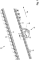
- Fig. 1 shows a schematic representation of the arrangement 10 according to the invention in a perspective view.
- the arrangement 10 is designed and set up for skinning poultry parts - not shown in the drawing - containing the poultry breast.
- the poultry parts are preferably poultry breast caps or front halves of poultry carcasses.
- the poultry skin to be removed is usually located over the breast fillet, but is not firmly attached to it. In the area of the respiratory fold, on the flanks of the poultry carcass, the skin is attached to the poultry carcass.
- the arrangement 10 comprises a conveyor device 11 which is designed and set up to convey the poultry parts in the conveying direction 24.
- a skinning device 12 is arranged along the conveying path formed by the conveyor device 11.
- the conveyor device 11 comprises saddle elements 13 which are designed and set up to receive the poultry parts.
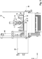
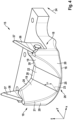
- FIGS 2 and 3 show the skinning device 12 according to the invention in detail in different views. In both figures, for reasons of better clarity, not the entire conveying direction 11 is shown, but only one of the saddle elements 13 is shown.
- the skinning device 12 comprises a rotating, profiled roller 14 and a guide element 15.
- the guide element 15 comprises flank guide elements 18 designed to guide the poultry part laterally.
- the flank guide elements 18 are designed to rest on the muscle meat of the poultry part, ie while the poultry skin is pulled off via the profiled roller 14, the flank guide elements 18 come into direct contact with the underlying muscle meat of the breast fillets.
- the flank guide elements 18 have inner guide surfaces 19 for this purpose.
- the Flank guide elements 18 therefore have a guiding and directing function to guide the poultry carcass in a defined manner and to guide it past the roller 14 without parts of the poultry carcass - with the exception of the skin - coming into contact with the roller 14.
- the flank guide elements 18 each comprise external guide surfaces 20 designed to guide the skin connected to the poultry part, wherein the external guide surfaces 20 each extend between the intake edge 16 and a separating edge 21, at which the inner guide surface 19 borders on the outer guide surface 20.
- the poultry skin is pulled over the separating edge 21 by the interaction of the rotating, driven profiled roller 14 and laterally over the flank guide elements 18. Described in a clear manner, the poultry skin "flows around" the guide element 15 laterally and is pulled off the poultry part via the intake gap 17.
- the inner guide surfaces 19 with their separating edge 21 are advantageously curved in a concave or essentially concave manner. It is particularly advantageous that the concavity of the inner guide surfaces 19 is designed to correspond essentially to the anatomy of the poultry part to be skinned, i.e., for example, it is adapted to the external shape of the outer fillets still on the poultry carcass. Depending on the type of poultry to be processed, the inner guide surfaces 19 can be designed differently. In any case, the inner guide surfaces 19 are preferably designed so that they come into contact with the outer fillets of the poultry part over as much of their surface as possible.
- the guide element 15 further preferably has a contact surface 22 arranged between the inner guide surfaces 19, which forms an inclined run-up ramp extending from the intake edge 16.
- the contact surface 22 is inclined by an angle ⁇ with respect to a roller tangential 23.
- the roller tangential 23 designates the tangential of the roller circumference which lies in the XY plane.
- the contact surface 22 is arranged inclined by the angle ⁇ with respect to the XY plane.
- Such an inclined contact surface 22 is in particular provided in the Figures 4 to 8
- the poultry parts conveyed in the conveying direction 24 run against this contact surface 22. Due to the inclination of the contact surface 22, the poultry parts are on the one hand compressed to a certain extent and at the same time raised slightly with respect to the Z axis, i.e. directed away from the roller 14, so that the previously described "flowing around" of the poultry skin around the flank guide elements 18 is additionally supported. Due to the comparatively larger clear width between the contact surface 22 and the saddle elements 13 in the entry area 26, the entry of the poultry part into the guide element 15 is largely free of resistance, so that a reliable entry of the poultry carcass between the inner guide surfaces 19 is guaranteed.
- the inclined arrangement of the contact surface 22 leads to a continuous reduction in the clear width in the direction of the exit area 27 of the guide element 15, so that the mechanical resistance against the conveying direction also continuously increases and the previously described lifting and compression effect occurs.
- the separating edge 21 is seamlessly connected to the contact surface edge 25 on each side.
- the contact surfaces 22 and the separating edge 21 form a closed envelope surface free of steps and projections, so that the poultry carcass can slide over.
- the contact surface edge 25 of the contact surface 22 designed as a ramp is preferably arranged directly adjacent to the intake edge 16.
- flank guide elements 18 are designed in such a way that the clear width between the inner guide surfaces 19 tapers in the conveying direction 24.
- the inner guide surfaces 19 are therefore not only curved in the XZ plane, but also form surfaces directed towards one another in the XZ plane.
- the inner guide surfaces 19 can for example be arranged at an angle in the XZ plane, or be curved as shown in the drawing.
- the inner guide surfaces 19 are therefore curved in one or more spatial directions.
- the inner guide surfaces 19 of the flank guide elements 18 each have end edges 28.
- the end edge 28 of one of the inner guide surfaces 19 is shorter than the respective section of the separating edge 21 of the same inner guide surface 19.
- the described geometry of the end edges 28 and the respective sections of the separating edge 21 thus determine the edge geometry of the inner guide surfaces 19.
- the inner guide surfaces 19 themselves are designed as envelope surfaces that span between this predetermined edge geometry. In other words, the inner guide surfaces 19 are arranged such that they span between the end edge 28 and the separating edge 21 of the respective inner guide surface 19.
- the separating edge 21, the contact surface edges 25 and/or the end edges 28 are rounded. This allows the skin and poultry part to slide more easily over the guide element 15 and at the same time prevents damage and injury to the muscle meat due to mechanical influences, which can ultimately lead to a final product of lower quality.
- the roller 14 is provided with a - for reasons of better overview only in Fig. 3 shown - drive unit 29 such that the peripheral speed of the roller 14 is greater than the conveying speed of the conveyor device 11.
- the skin that has reached the intake gap 17 is thus pulled off at a higher speed compared to the conveying speed of the poultry part.
- a correspondingly high tensile force is exerted on the poultry skin, which deforms elastically to a certain extent under the action of the force.
- the speed difference is selected so that the developing tensile force is large enough to detach the skin from the poultry carcass in areas that are not grown together with the poultry carcass and to let it slide over the guide element 15, but there is no uncontrolled tearing of the skin from the poultry part or ripping of the skin.
- the roller 14 preferably has a lateral surface profile inclined relative to its axis of rotation 30 in the area of the flank guide elements 18.
- the roller 14 is therefore provided with a toothing in these areas. This ensures that the skin is not only pulled in the circumferential direction of the roller 14, but the skin is distributed in a further directional component, namely parallel to the axis of rotation, on the circumferential surface 32 of the roller 14.
- the inclination of the lateral surface profiling in the area of the flank guide elements 18 - and possibly laterally beyond them - is inclined towards the front sides of the roller in the opposite direction to the direction of rotation of the roller 14. This causes the skin entering the intake gap 17 to be additionally pulled laterally outwards and thus spreads out over the circumferential surface 32 of the roller 14.
- the roller 14 has a shell surface profile aligned parallel to the rotational axis 30 of the roller 14 in the area of the contact surface 22 forming the run-up ramp.
- This offers the advantage that when the skin first comes into contact with the roller 14 and the intake edge 16, the skin is drawn into the intake gap 17 as quickly as possible parallel to the conveying direction 24 and is thus gripped with high reliability. After the first skin area has been drawn into the intake gap 17 and has extended over the entire width of the shell profile aligned parallel to the rotational axis 30, the skin is spread evenly over the peripheral surface 32 of the roller via the aforementioned shell profiles in the area of the flank guide elements 18.
- the peripheral surface 32 of the roller 14 is therefore divided into three areas.
- An inner area 33 which is essentially assigned to the contact surface 22, has the aforementioned shell profiling with a profile aligned parallel to the axis of rotation 30, while the described shell profiling, inclined relative to the axis of rotation 30, is arranged in the outer areas 34.
- the skinning device 12 is arranged so as to be resiliently supported relative to the conveyor device 11.
- the entire skinning device 12 deflects downwards against the spring preload by the pneumatic element 40 by means of a pivoting movement as soon as the poultry part passes through the guide element 15 with corresponding compression.
- the compression caused on the poultry part by the guide element 15 is compensated to a certain extent, so that the processing of poultry bodies with a different anatomy and size is possible.
- pneumatic element 40 instead of the pneumatic element 40, other elements with a spring effect, for example tension springs, can be used as an alternative.
- the pneumatic element 40 offers the advantage that the spring force can be adjusted by applying compressed air and can be optimally adapted to the respective production requirements.
- the pneumatic element 40 is controlled in a supporting or exclusively active manner in order to cause the skinning device to deflect and to return it to the starting position as quickly as possible.
- the flank guide elements 18 each comprise cutting means 36 designed to separate the connection between the skin and the poultry part.
- the cutting means 36 By means of the cutting means 36, the connection between the skin and the poultry carcass is severed in the area of the respiratory fold and the skin is thus completely separated from the carcass. In this way, a controlled cut is made.
- the last skin connection is severed precisely at exactly the right place. In this way, an optimal separating cut is made for every poultry geometry thanks to a surprisingly simple structural design of the arrangement 10 according to the invention.
- the cutting means 36 are arranged on the output side, downstream of the guide element 15 with respect to the conveying direction 24. According to the invention, the cutting means 36 therefore only sever the skin connection shortly before the poultry part has completely passed the guide element 15.
- each of the cutting means 36 are preferably inclined relative to the conveying direction 24.
- the knives are designed as triangular knives.
- the cutting means 36 as shown in the Figures 5 and 6 shown, with a sickle-shaped cutting edge 37. This offers the advantage that the skin that has grown together with the carcass "gets caught" in the concave cutting edge shape. This ensures that the skin connection is always severed by the cutting means 36. The skin cannot therefore slip over the cutting edge 37 without being completely severed.
- the cutting means 36 are preferably designed as double blades 38, i.e. they each have cutting edges 37 on their front and back sides. This offers the advantage that a blunt cutting edge 37 can be easily replaced by rotating the cutting means 36 by 180°, without having to replace the entire cutting means 36.
- the cutting edge 37 is inclined such that the cutting edges 37, starting from the flank guide element 18, extend against the conveying direction 24 In this way, a function comparable to the embodiment with a sickle-shaped cutting edge 37 is achieved, namely preventing the skin from sliding over the cutting means 37 without completely severing the skin area.
- the cutting edges are also preferably bevelled on both sides.
- the cutting means 36 are mounted transversely to the conveying direction 24 in a spring-loaded manner (not shown in the drawing). The cutting means 36 thus move sideways if the width of the poultry body requires this. The cutting means 36 are thus set up to adapt themselves to the poultry part.
- the method according to the invention for skinning poultry parts containing the poultry breast comprises the steps of: conveying the poultry parts in the conveying direction 24 along the skinning device 12 by means of the saddle elements 13 of the conveying device 11, rotatingly driving at least one profiled roller 14, whereby the roller 14 together with a draw-in edge 16 of a guide element 15 forms a draw-in gap 17 for grasping the skin on the poultry breast side.
- the skin is grasped automatically by means of the draw-in gap 17, while the poultry part is guided laterally by means of flank guide elements 18.
- the guidance takes place by placing inner guide surfaces 19 on the muscle meat of the poultry part.
- the skin connected to the poultry part side is preferably guided by means of the outer guide surfaces 20 of the flank guide elements 18, which each extend between the intake edge 16 and a separating edge 21, at which the inner guide surface 19 borders on the outer guide surface 20.
- At least partial areas of the poultry part are elastically compressed by conveying it over a ramp, wherein the ramp is formed by a contact surface 22 arranged between the inner guide surfaces 19.
- the contact surface 22 of the run-up ramp is arranged at an angle ⁇ relative to a roller tangential 23, starting from the intake edge 16.
- the poultry part is additionally compressed laterally transversely to the conveying direction 24 by means of the flank guide elements 18, the clear width of which between the inner guide surfaces 19 tapers in the conveying direction 24.
- roller 14 is driven by means of a drive unit 29, so that the peripheral speed of the roller 14 is greater than the conveying speed of the conveyor device 11.
- the skin is pulled off at least with a partial component in the direction of the end faces 39 of the roller 14 by means of a lateral surface profiling of the roller 14 in the region of the flank guide elements 18, which is aligned at an angle to the axis of rotation 30 of the roller 14.
- the skin is drawn into the intake gap 17 in the region of the run-up ramp in the direction of rotation of the roller 14 by means of a lateral surface profiling aligned parallel to the axis of rotation 30 of the roller 14.
- the skinning device 12 deflects slightly relative to the conveyor device 11 when passing one of the poultry parts or a poultry carcass.
Landscapes
- Life Sciences & Earth Sciences (AREA)
- Engineering & Computer Science (AREA)
- Food Science & Technology (AREA)
- Wood Science & Technology (AREA)
- Zoology (AREA)
- Processing Of Meat And Fish (AREA)
Claims (30)
- Agencement (10) pour dépouiller des parties de volaille contenant la poitrine de volaille, avecun dispositif de transport (11) qui comprend des éléments de selle (13) configurés le long d'un dispositif de dépouillement (12) pour transporter les parties de volaille dans la direction de transport (24), etle dispositif de dépouillement (12) comprend au moins un cylindre profilé (14) entraîné en rotation ainsi qu'un élément de guidage (15), le cylindre (14) étant adapté, conjointement avec un bord d'introduction (16) de l'élément de guidage (15), pour former une fente d'introduction (17) pour saisir la peau du côté de la poitrine de volaille,l'élément de guidage (15) comprenant des éléments de guidage de flanc (18) adaptés respectivement pour le guidage latéral de la partie de volaille, et les éléments de guidage de flanc (18) présentant des surfaces de guidage intérieures (19) adaptées pour s'appuyer sur la chair musculaire de la partie de volaille,caractérisé en ce queles éléments de guidage de flanc (18) comprennent respectivement des moyens de coupe (36) adaptés pour séparer la liaison entre la peau et la partie de volaille.
- Agencement selon la revendication 1, caractérisé en ce que les éléments de guidage de flanc (18) comprennent respectivement des surfaces de guidage extérieures (20) adaptées pour guider la peau reliée du côté de la partie de volaille, les surfaces de guidage extérieures (20) s'étendant respectivement entre le bord d'introduction (16) et un bord de séparation (21) au niveau duquel la surface de guidage intérieure (19) est respectivement adjacente à la surface de guidage extérieure (20).
- Agencement selon la revendication 2, caractérisé en ce que les surfaces de guidage intérieures (19) sont chacune incurvées de manière au moins essentiellement concave avec leur bord de séparation (21).
- Agencement selon l'une quelconque des revendications 1 à 3, caractérisé en ce que l'élément de guidage (15) comprend une surface d'appui (22) agencée entre les surfaces de guidage intérieures (19), la surface d'appui (22) formant, à partir du bord d'introduction (16), une rampe de montée inclinée d'un angle α par rapport à une tangente au cylindre (23).
- Agencement selon l'une quelconque des revendications 2 à 4, caractérisé en ce que le bord de séparation (21) se raccorde chaque fois latéralement au bord de surface d'appui (25) sans soudure.
- Agencement selon la revendication 5, caractérisé en ce que le bord de surface d'appui (25) de la surface d'appui (22) est adapté de manière à être directement adjacent au bord d'introduction (16).
- Agencement selon l'une quelconque des revendications 1 à 4, caractérisé en ce que les éléments de guidage de flanc (18) sont configurés de telle sorte que la largeur libre entre les surfaces de guidage intérieures (19) se rétrécit dans la direction de transport (24).
- Agencement selon l'une quelconque des revendications 1 à 7, caractérisé en ce que les surfaces de guidage intérieures (19) des éléments de guidage de flanc (18) présentent respectivement un bord d'extrémité (28), le bord d'extrémité (28) de l'une des surfaces de guidage intérieures (19) étant respectivement plus court que la section respective du bord de séparation (21) de la même surface de guidage intérieure.
- Agencement selon la revendication 8, caractérisé en ce que chacune des surfaces de guidage intérieures (19) est configurée sous forme de surface enveloppante qui s'étend entre le bord d'extrémité (28) et le bord de séparation (21) de la surface de guidage intérieure respective (19).
- Agencement selon la revendication 8 ou 9, caractérisé en ce que le bord de séparation (21), les bords de surface d'appui (25) et/ou les bords d'extrémité (28) sont configurés sous forme arrondie.
- Agencement selon l'une quelconque des revendications 1 à 10, caractérisé en ce que le cylindre (14) est entraîné au moyen d'un groupe d'entraînement (29) de telle sorte que la vitesse périphérique du cylindre (14) est supérieure à la vitesse de transport du dispositif de transport (11).
- Agencement selon l'une quelconque des revendications 1 à 11, caractérisé en ce que le cylindre (14) présente, dans la zone des éléments de guidage de flanc (18), un profilage de surface d'enveloppe incliné par rapport à son axe de rotation (30).
- Agencement selon la revendication 12, caractérisé en ce que les profilages de surface d'enveloppe dans la zone des éléments de guidage de flanc (18) sont respectivement inclinés vers les côtés frontaux (39) du cylindre (14) à l'encontre de la direction de rotation du cylindre (14).
- Agencement selon l'une quelconque des revendications 4 à 13, caractérisé en ce que le cylindre (14) présente, dans la zone de la surface d'appui (22) formant la rampe de montée, un profilage de surface d'enveloppe orienté parallèlement à l'axe de rotation (30) du cylindre (14).
- Agencement selon l'une quelconque des revendications 1 à 14, caractérisé en ce que le dispositif de dépouillement (12) est agencé en étant monté de manière à pouvoir s'écarter élastiquement par rapport au dispositif de transport (11).
- Agencement selon l'une quelconque des revendications 1 à 15, caractérisé en ce que les moyens de coupe (36) sont agencés du côté de la sortie, en aval de l'élément de guidage (15) par rapport à la direction de transport (24).
- Agencement selon l'une quelconque des revendications 1 à 15, caractérisé en ce que chacun des moyens de coupe (36) présente un bord de coupe (37) qui est configuré sous forme inclinée par rapport à la direction de transport (24).
- Agencement selon la revendication 17, caractérisé en ce que le bord de coupe (37) est configuré en forme de croissant.
- Agencement selon la revendication 17 ou 18, caractérisé en ce que les bords de coupe (37) sont respectivement configurés avec un chanfrein des deux côtés.
- Agencement selon l'une quelconque des revendications 1 à 19, caractérisé en ce que les moyens de coupe (36) sont montés de manière à pouvoir s'écarter élastiquement transversalement à la direction de transport (24).
- Procédé de dépouillement de parties de volaille contenant la poitrine de volaille, comprenant les étapes :le transport des parties de volaille dans la direction de transport (24) le long d'un dispositif de dépouillement (12) au moyen d'éléments de selle (13) d'un dispositif de transport (11),l'entraînement en rotation d'au moins un cylindre profilé (14), le cylindre (14) formant conjointement avec un bord d'introduction (16) d'un élément de guidage (15) une fente d'introduction (17) pour saisir la peau du côté de la poitrine de volaille,la saisie automatique de la peau au moyen de la fente d'introduction (17),
etle guidage latéral respectif de la partie de volaille au moyen d'éléments de guidage de flanc (18) par appui de surfaces de guidage intérieures (19) sur la chair musculaire de la partie de volaille,caractérisé parla séparation de la liaison restante entre la peau et la partie de volaille au moyen de moyens de coupe (36),la séparation étant effectuée du côté de la sortie, c'est-à-dire juste avant que la partie de volaille n'ait complètement passé l'élément de guidage (15). - Procédé selon la revendication 21, caractérisé par le guidage de la peau reliée du côté de la partie de volaille au moyen de surfaces de guidage extérieures (20) des éléments de guidage de flanc (18), qui s'étendent respectivement entre le bord d'introduction (16) et un bord de séparation (21), au niveau duquel la surface de guidage intérieure (19) est respectivement adjacente à la surface de guidage extérieure (20).
- Procédé selon la revendication 21 ou 22, caractérisé par un refoulement élastique d'au moins des zones partielles de la partie de volaille par transport de celle-ci sur une rampe de montée formée par une surface d'appui (22) agencée entre les surfaces de guidage intérieures (19), la surface d'appui (22) de la rampe de montée étant inclinée d'un angle α par rapport à une tangente au cylindre (23) en partant du bord d'introduction (16).
- Procédé selon l'une quelconque des revendications 21 à 23, caractérisé par un refoulement latéral de la partie de volaille, transversalement à la direction de transport (24), au moyen des éléments de guidage de flanc (18) dont la largeur libre entre les surfaces de guidage intérieures (19) se rétrécit dans la direction de transport (24).
- Procédé selon l'une quelconque des revendications 21 à 24, caractérisé par l'entraînement du cylindre (14) au moyen d'un groupe d'entraînement (29) de telle sorte que la vitesse périphérique du cylindre (14) est supérieure à la vitesse de transport du dispositif de transport (11).
- Procédé selon l'une quelconque des revendications 21 à 25, caractérisé par le retrait de la peau, au moins avec une composante partielle, en direction des côtés frontaux (39) du cylindre (14) au moyen d'un profilage de surface d'enveloppe du cylindre (14) dans la zone des éléments de guidage de flanc (18), qui est orienté de manière inclinée par rapport à l'axe de rotation (30) du cylindre (14).
- Procédé selon l'une quelconque des revendications 21 à 26, caractérisé par l'introduction de la peau dans la fente d'introduction (17) dans la zone de la rampe de montée dans la direction circonférentielle du cylindre (14) au moyen d'un profilage de surface d'enveloppe orienté parallèlement à l'axe de rotation (30) du cylindre (14).
- Procédé selon l'une quelconque des revendications 21 à 27, caractérisé par un écartement élastique du dispositif de dépouillement (12) par rapport au dispositif de transport (11) lors du passage de l'une des carcasses de volaille.
- Procédé selon l'une quelconque des revendications 21 à 28, caractérisé en ce que la séparation est effectuée au moyen de moyens de coupe (36) présentant un bord de coupe (37) incliné par rapport à la direction de transport (24).
- Procédé selon l'une quelconque des revendications 21 à 29, caractérisé par un écartement élastique des moyens de coupe (36) transversalement à la direction de transport (24).
Priority Applications (1)
| Application Number | Priority Date | Filing Date | Title |
|---|---|---|---|
| PL18715635.1T PL3772968T3 (pl) | 2018-03-29 | 2018-03-29 | Układ i sposób skórowania części drobiowych zawierających pierś drobiową |
Applications Claiming Priority (1)
| Application Number | Priority Date | Filing Date | Title |
|---|---|---|---|
| PCT/EP2018/058206 WO2019185155A1 (fr) | 2018-03-29 | 2018-03-29 | Système et procédé pour la dépouille des pièces de volaille contenant la poitrine de volaille |
Publications (2)
| Publication Number | Publication Date |
|---|---|
| EP3772968A1 EP3772968A1 (fr) | 2021-02-17 |
| EP3772968B1 true EP3772968B1 (fr) | 2024-11-20 |
Family
ID=61899258
Family Applications (1)
| Application Number | Title | Priority Date | Filing Date |
|---|---|---|---|
| EP18715635.1A Active EP3772968B1 (fr) | 2018-03-29 | 2018-03-29 | Agencement et procédé de dépouillement de parties de volaille contenant la poitrine de volaille |
Country Status (7)
| Country | Link |
|---|---|
| US (1) | US11388906B2 (fr) |
| EP (1) | EP3772968B1 (fr) |
| CN (1) | CN111970931B (fr) |
| DK (1) | DK3772968T3 (fr) |
| ES (1) | ES3002717T3 (fr) |
| PL (1) | PL3772968T3 (fr) |
| WO (1) | WO2019185155A1 (fr) |
Families Citing this family (1)
| Publication number | Priority date | Publication date | Assignee | Title |
|---|---|---|---|---|
| US11102990B2 (en) * | 2019-04-10 | 2021-08-31 | Prime Equipment Group, Llc | Keel strip removal apparatus and method |
Citations (2)
| Publication number | Priority date | Publication date | Assignee | Title |
|---|---|---|---|---|
| EP3041361B1 (fr) * | 2013-09-02 | 2017-05-24 | Marel Stork Poultry Processing B.V. | Installation de dépouillement et procédé destiné à enlever la peau de parties de volailles abattues |
| EP3068229B1 (fr) * | 2013-11-13 | 2018-01-17 | Marel Stork Poultry Processing B.V. | Système, procédé et dispositif de carrousel pour retirer la peau de produits volaillers de type patte entière ou pilon déplumé |
Family Cites Families (11)
| Publication number | Priority date | Publication date | Assignee | Title |
|---|---|---|---|---|
| NL8302207A (nl) * | 1983-06-21 | 1985-01-16 | Stork Pmt | Inrichting voor het afscheiden van het vel van een deel van een vogel. |
| US4723339A (en) * | 1986-04-21 | 1988-02-09 | Stork Pmt B.V. | Breast skinner |
| DE59303271D1 (de) * | 1993-12-17 | 1996-08-22 | Nordischer Maschinenbau | Vorrichtung zum Entfernen der Haut von den Körpern geschlachteten Geflügels |
| WO2004052106A1 (fr) | 2002-12-11 | 2004-06-24 | Mayekawa Mfg.Co.,Ltd. | Equipement de traitement de desossement automatique pour la moitie superieure de corps de poulet abattu |
| BRPI0622405B1 (pt) * | 2005-12-09 | 2021-03-23 | Stork Pmt B.V. | Método e dispositivo para processar uma parte da carcaça da ave abatida |
| US8272927B2 (en) * | 2009-10-21 | 2012-09-25 | Remington Holdings Llc | Poultry shoulder and neck skinner |
| NL2003900C2 (en) | 2009-12-03 | 2011-06-06 | Stork P M T B V | Device and method for processing a carcass part of slaughtered poultry. |
| US20130270413A1 (en) * | 2010-12-20 | 2013-10-17 | John Wilber | Portable Stand for an Information Display Article |
| CN105636448B (zh) * | 2013-10-04 | 2018-05-18 | 马瑞奥肉类加工有限公司 | 用于在通过输送装置输送时从动物尸体去除外皮的剥皮设备及相关方法和系统 |
| NL2019926B1 (en) * | 2017-11-16 | 2019-05-22 | Meyn Food Processing Tech Bv | Deskinning apparatus and method for deskinning a poultry leg or part of a poultry leg |
| NL2024085B1 (en) * | 2019-10-23 | 2021-07-13 | Meyn Food Processing Tech Bv | Deskinning apparatus and method for deskinning a poultry leg or part of a poultry leg |
-
2018
- 2018-03-29 DK DK18715635.1T patent/DK3772968T3/da active
- 2018-03-29 CN CN201880091805.8A patent/CN111970931B/zh active Active
- 2018-03-29 EP EP18715635.1A patent/EP3772968B1/fr active Active
- 2018-03-29 US US16/982,840 patent/US11388906B2/en active Active
- 2018-03-29 PL PL18715635.1T patent/PL3772968T3/pl unknown
- 2018-03-29 WO PCT/EP2018/058206 patent/WO2019185155A1/fr not_active Ceased
- 2018-03-29 ES ES18715635T patent/ES3002717T3/es active Active
Patent Citations (2)
| Publication number | Priority date | Publication date | Assignee | Title |
|---|---|---|---|---|
| EP3041361B1 (fr) * | 2013-09-02 | 2017-05-24 | Marel Stork Poultry Processing B.V. | Installation de dépouillement et procédé destiné à enlever la peau de parties de volailles abattues |
| EP3068229B1 (fr) * | 2013-11-13 | 2018-01-17 | Marel Stork Poultry Processing B.V. | Système, procédé et dispositif de carrousel pour retirer la peau de produits volaillers de type patte entière ou pilon déplumé |
Also Published As
| Publication number | Publication date |
|---|---|
| CN111970931A (zh) | 2020-11-20 |
| WO2019185155A1 (fr) | 2019-10-03 |
| US20210051968A1 (en) | 2021-02-25 |
| BR112020019132A2 (pt) | 2021-01-12 |
| ES3002717T3 (en) | 2025-03-07 |
| US11388906B2 (en) | 2022-07-19 |
| DK3772968T3 (da) | 2025-02-03 |
| CN111970931B (zh) | 2022-05-24 |
| EP3772968A1 (fr) | 2021-02-17 |
| PL3772968T3 (pl) | 2025-03-17 |
Similar Documents
| Publication | Publication Date | Title |
|---|---|---|
| EP2207426B1 (fr) | Dispositif pour enlever par découpage les arêtes latérales de poissons étêtés, abattus et ouverts au niveau de leur cavité abdominale et machine à fileter pour prélever les filets de poissons étêtés, abattus et ouverts au niveau de leur cavité abdominale comprenant un tel dispositif | |
| DE19881497C1 (de) | Verfahren zum Gewinnen des Muskelfleisches von Fischen und Einrichtung zur Durchführung des Verfahrens | |
| EP2442662B9 (fr) | Dispositif et procédé de filetage de poissons étêtés et éviscérés | |
| WO2002003807A1 (fr) | Procede et dispositif permettant de lever des filets sur des poissons tues, etetes et vides | |
| DD254322A5 (de) | Vorrichtung zum gewinnen fleischgraetenfreier filets von fischen | |
| DD291687A5 (de) | Verfahren zum maschinellen gewinnen des fleisches von gefluegelkoerpern und vorrichtung zur durchfuehrung des verfahrens | |
| WO2013159814A1 (fr) | Procédé pour réaliser une coupe de filets afin de lever des filets de poissons, procédé pour réaliser une coupe de filets selon le procédé ainsi qu'une paire de couteaux rotatifs mis au point pour le procédé et le dispositif et couteaux rotatifs | |
| DE3723860C1 (de) | Vorrichtung zum Filetieren von Fischen | |
| EP2587927B9 (fr) | Dispositif et procédé destiné à détacher intégralement au moins une partie du cartilage de poitrine à partir d'une carcasse de volaille libérée de son blanc | |
| DE3735849A1 (de) | Verfahren zum entfernen der fluegel von gefluegelkoerpern und einrichtung zur durchfuehrung des verfahrens | |
| DE102010030349A1 (de) | Fördertrommel der Tabak verarbeitenden Industrie | |
| DE60220033T2 (de) | Vorrichtung und verfahren zur auftrennung der gummierung eines förderbands | |
| EP0641519B1 (fr) | Procédé et dispositif pour l'enlèvement d'une couche superficielle | |
| DE2714468C2 (de) | Metallstreifen mit voneinander beabstandeten Klingen zur Herstellung chirurgischer Klingen und Verfahren zur Aufbereitung | |
| EP2877031B1 (fr) | Dispositif pour traiter des poissons | |
| DE202009017070U1 (de) | Vorrichtung zum Entfernen eines Geflügelbrustknorpels | |
| WO2022268602A1 (fr) | Appareil pour retirer par découpe des arrêtes de flanc de poissons abattus décapités qui ont de préférence des cavités abdominales ouvertes, procédé, et machine de filetage pour le filetage de poissons décapités, abattus qui ont de préférence des cavités abdominales ouvertes, en particulier comprenant un tel appareil | |
| DE69423763T2 (de) | Verfahren und vorrichtung zum enthäuten von wurst | |
| EP2420143B1 (fr) | Dispositif et procédé de coupe automatisée des ailes de corps de volailles | |
| EP3772968A1 (fr) | Système et procédé pour la dépouille des pièces de volaille contenant la poitrine de volaille | |
| DE102020108616B4 (de) | Vorrichtung und Verfahren zum Gewinnen des inneren Rückenfleisches von Geflügel | |
| DD216613A5 (de) | Einrichtung an fischfiletiermaschinen | |
| WO2002076220A1 (fr) | Procede pour fileter des poissons evisceres, a cavite abdominale ouverte, et dispositif pour mettre en oeuvre ledit procede | |
| WO2025172183A1 (fr) | Agencement de lames, dispositif de coupe et procédé d'élimination d'une fourchette d'une carcasse de volaille ou de parties de celle-ci comprenant toujours au moins la fourchette, un bréchet, des tendons et/ou des ligaments reliés à la fourchette, et des filets internes et filets externes | |
| DE10034936A1 (de) | Verfahren und Vorrichtung zum Filetieren geköpfter, geschlachteter und in ihrer Bauchhöhle geöffneter Fische |
Legal Events
| Date | Code | Title | Description |
|---|---|---|---|
| STAA | Information on the status of an ep patent application or granted ep patent |
Free format text: STATUS: UNKNOWN |
|
| STAA | Information on the status of an ep patent application or granted ep patent |
Free format text: STATUS: THE INTERNATIONAL PUBLICATION HAS BEEN MADE |
|
| PUAI | Public reference made under article 153(3) epc to a published international application that has entered the european phase |
Free format text: ORIGINAL CODE: 0009012 |
|
| STAA | Information on the status of an ep patent application or granted ep patent |
Free format text: STATUS: REQUEST FOR EXAMINATION WAS MADE |
|
| 17P | Request for examination filed |
Effective date: 20201021 |
|
| AK | Designated contracting states |
Kind code of ref document: A1 Designated state(s): AL AT BE BG CH CY CZ DE DK EE ES FI FR GB GR HR HU IE IS IT LI LT LU LV MC MK MT NL NO PL PT RO RS SE SI SK SM TR |
|
| AX | Request for extension of the european patent |
Extension state: BA ME |
|
| DAV | Request for validation of the european patent (deleted) | ||
| DAX | Request for extension of the european patent (deleted) | ||
| GRAP | Despatch of communication of intention to grant a patent |
Free format text: ORIGINAL CODE: EPIDOSNIGR1 |
|
| STAA | Information on the status of an ep patent application or granted ep patent |
Free format text: STATUS: GRANT OF PATENT IS INTENDED |
|
| INTG | Intention to grant announced |
Effective date: 20240219 |
|
| GRAJ | Information related to disapproval of communication of intention to grant by the applicant or resumption of examination proceedings by the epo deleted |
Free format text: ORIGINAL CODE: EPIDOSDIGR1 |
|
| STAA | Information on the status of an ep patent application or granted ep patent |
Free format text: STATUS: REQUEST FOR EXAMINATION WAS MADE |
|
| GRAP | Despatch of communication of intention to grant a patent |
Free format text: ORIGINAL CODE: EPIDOSNIGR1 |
|
| STAA | Information on the status of an ep patent application or granted ep patent |
Free format text: STATUS: GRANT OF PATENT IS INTENDED |
|
| INTG | Intention to grant announced |
Effective date: 20240626 |
|
| P01 | Opt-out of the competence of the unified patent court (upc) registered |
Free format text: CASE NUMBER: APP_36491/2024 Effective date: 20240618 |
|
| GRAS | Grant fee paid |
Free format text: ORIGINAL CODE: EPIDOSNIGR3 |
|
| GRAA | (expected) grant |
Free format text: ORIGINAL CODE: 0009210 |
|
| STAA | Information on the status of an ep patent application or granted ep patent |
Free format text: STATUS: THE PATENT HAS BEEN GRANTED |
|
| AK | Designated contracting states |
Kind code of ref document: B1 Designated state(s): AL AT BE BG CH CY CZ DE DK EE ES FI FR GB GR HR HU IE IS IT LI LT LU LV MC MK MT NL NO PL PT RO RS SE SI SK SM TR |
|
| REG | Reference to a national code |
Ref country code: GB Ref legal event code: FG4D Free format text: NOT ENGLISH |
|
| REG | Reference to a national code |
Ref country code: CH Ref legal event code: EP |
|
| REG | Reference to a national code |
Ref country code: DE Ref legal event code: R096 Ref document number: 502018015337 Country of ref document: DE |
|
| REG | Reference to a national code |
Ref country code: IE Ref legal event code: FG4D Free format text: LANGUAGE OF EP DOCUMENT: GERMAN |
|
| REG | Reference to a national code |
Ref country code: DK Ref legal event code: T3 Effective date: 20250129 |
|
| REG | Reference to a national code |
Ref country code: NL Ref legal event code: FP |
|
| REG | Reference to a national code |
Ref country code: ES Ref legal event code: FG2A Ref document number: 3002717 Country of ref document: ES Kind code of ref document: T3 Effective date: 20250307 |
|
| REG | Reference to a national code |
Ref country code: LT Ref legal event code: MG9D |
|
| PG25 | Lapsed in a contracting state [announced via postgrant information from national office to epo] |
Ref country code: HR Free format text: LAPSE BECAUSE OF FAILURE TO SUBMIT A TRANSLATION OF THE DESCRIPTION OR TO PAY THE FEE WITHIN THE PRESCRIBED TIME-LIMIT Effective date: 20241120 Ref country code: IS Free format text: LAPSE BECAUSE OF FAILURE TO SUBMIT A TRANSLATION OF THE DESCRIPTION OR TO PAY THE FEE WITHIN THE PRESCRIBED TIME-LIMIT Effective date: 20250320 Ref country code: PT Free format text: LAPSE BECAUSE OF FAILURE TO SUBMIT A TRANSLATION OF THE DESCRIPTION OR TO PAY THE FEE WITHIN THE PRESCRIBED TIME-LIMIT Effective date: 20250320 |
|
| PG25 | Lapsed in a contracting state [announced via postgrant information from national office to epo] |
Ref country code: FI Free format text: LAPSE BECAUSE OF FAILURE TO SUBMIT A TRANSLATION OF THE DESCRIPTION OR TO PAY THE FEE WITHIN THE PRESCRIBED TIME-LIMIT Effective date: 20241120 |
|
| PG25 | Lapsed in a contracting state [announced via postgrant information from national office to epo] |
Ref country code: BG Free format text: LAPSE BECAUSE OF FAILURE TO SUBMIT A TRANSLATION OF THE DESCRIPTION OR TO PAY THE FEE WITHIN THE PRESCRIBED TIME-LIMIT Effective date: 20241120 |
|
| PG25 | Lapsed in a contracting state [announced via postgrant information from national office to epo] |
Ref country code: NO Free format text: LAPSE BECAUSE OF FAILURE TO SUBMIT A TRANSLATION OF THE DESCRIPTION OR TO PAY THE FEE WITHIN THE PRESCRIBED TIME-LIMIT Effective date: 20250220 |
|
| PG25 | Lapsed in a contracting state [announced via postgrant information from national office to epo] |
Ref country code: LV Free format text: LAPSE BECAUSE OF FAILURE TO SUBMIT A TRANSLATION OF THE DESCRIPTION OR TO PAY THE FEE WITHIN THE PRESCRIBED TIME-LIMIT Effective date: 20241120 Ref country code: GR Free format text: LAPSE BECAUSE OF FAILURE TO SUBMIT A TRANSLATION OF THE DESCRIPTION OR TO PAY THE FEE WITHIN THE PRESCRIBED TIME-LIMIT Effective date: 20250221 |
|
| PG25 | Lapsed in a contracting state [announced via postgrant information from national office to epo] |
Ref country code: RS Free format text: LAPSE BECAUSE OF FAILURE TO SUBMIT A TRANSLATION OF THE DESCRIPTION OR TO PAY THE FEE WITHIN THE PRESCRIBED TIME-LIMIT Effective date: 20250220 |
|
| PG25 | Lapsed in a contracting state [announced via postgrant information from national office to epo] |
Ref country code: SM Free format text: LAPSE BECAUSE OF FAILURE TO SUBMIT A TRANSLATION OF THE DESCRIPTION OR TO PAY THE FEE WITHIN THE PRESCRIBED TIME-LIMIT Effective date: 20241120 |
|
| PGFP | Annual fee paid to national office [announced via postgrant information from national office to epo] |
Ref country code: ES Payment date: 20250416 Year of fee payment: 8 |
|
| PGFP | Annual fee paid to national office [announced via postgrant information from national office to epo] |
Ref country code: IT Payment date: 20250430 Year of fee payment: 8 |
|
| PG25 | Lapsed in a contracting state [announced via postgrant information from national office to epo] |
Ref country code: EE Free format text: LAPSE BECAUSE OF FAILURE TO SUBMIT A TRANSLATION OF THE DESCRIPTION OR TO PAY THE FEE WITHIN THE PRESCRIBED TIME-LIMIT Effective date: 20241120 |
|
| PG25 | Lapsed in a contracting state [announced via postgrant information from national office to epo] |
Ref country code: RO Free format text: LAPSE BECAUSE OF FAILURE TO SUBMIT A TRANSLATION OF THE DESCRIPTION OR TO PAY THE FEE WITHIN THE PRESCRIBED TIME-LIMIT Effective date: 20241120 |
|
| PG25 | Lapsed in a contracting state [announced via postgrant information from national office to epo] |
Ref country code: SK Free format text: LAPSE BECAUSE OF FAILURE TO SUBMIT A TRANSLATION OF THE DESCRIPTION OR TO PAY THE FEE WITHIN THE PRESCRIBED TIME-LIMIT Effective date: 20241120 |
|
| PG25 | Lapsed in a contracting state [announced via postgrant information from national office to epo] |
Ref country code: CZ Free format text: LAPSE BECAUSE OF FAILURE TO SUBMIT A TRANSLATION OF THE DESCRIPTION OR TO PAY THE FEE WITHIN THE PRESCRIBED TIME-LIMIT Effective date: 20241120 |
|
| REG | Reference to a national code |
Ref country code: DE Ref legal event code: R097 Ref document number: 502018015337 Country of ref document: DE |
|
| PG25 | Lapsed in a contracting state [announced via postgrant information from national office to epo] |
Ref country code: SE Free format text: LAPSE BECAUSE OF FAILURE TO SUBMIT A TRANSLATION OF THE DESCRIPTION OR TO PAY THE FEE WITHIN THE PRESCRIBED TIME-LIMIT Effective date: 20241120 |
|
| PLBE | No opposition filed within time limit |
Free format text: ORIGINAL CODE: 0009261 |
|
| STAA | Information on the status of an ep patent application or granted ep patent |
Free format text: STATUS: NO OPPOSITION FILED WITHIN TIME LIMIT |
|
| PG25 | Lapsed in a contracting state [announced via postgrant information from national office to epo] |
Ref country code: MC Free format text: LAPSE BECAUSE OF FAILURE TO SUBMIT A TRANSLATION OF THE DESCRIPTION OR TO PAY THE FEE WITHIN THE PRESCRIBED TIME-LIMIT Effective date: 20241120 |
|
| 26N | No opposition filed |
Effective date: 20250821 |
|
| REG | Reference to a national code |
Ref country code: CH Ref legal event code: H13 Free format text: ST27 STATUS EVENT CODE: U-0-0-H10-H13 (AS PROVIDED BY THE NATIONAL OFFICE) Effective date: 20251023 |
|
| PG25 | Lapsed in a contracting state [announced via postgrant information from national office to epo] |
Ref country code: LU Free format text: LAPSE BECAUSE OF NON-PAYMENT OF DUE FEES Effective date: 20250329 |
|
| REG | Reference to a national code |
Ref country code: BE Ref legal event code: MM Effective date: 20250331 |
|
| PG25 | Lapsed in a contracting state [announced via postgrant information from national office to epo] |
Ref country code: BE Free format text: LAPSE BECAUSE OF NON-PAYMENT OF DUE FEES Effective date: 20250331 |
|
| PG25 | Lapsed in a contracting state [announced via postgrant information from national office to epo] |
Ref country code: CH Free format text: LAPSE BECAUSE OF NON-PAYMENT OF DUE FEES Effective date: 20250331 |
|
| PG25 | Lapsed in a contracting state [announced via postgrant information from national office to epo] |
Ref country code: IE Free format text: LAPSE BECAUSE OF NON-PAYMENT OF DUE FEES Effective date: 20250329 |
|
| PGFP | Annual fee paid to national office [announced via postgrant information from national office to epo] |
Ref country code: GB Payment date: 20260324 Year of fee payment: 9 |
|
| PGFP | Annual fee paid to national office [announced via postgrant information from national office to epo] |
Ref country code: DK Payment date: 20260323 Year of fee payment: 9 Ref country code: DE Payment date: 20260320 Year of fee payment: 9 |
|
| PGFP | Annual fee paid to national office [announced via postgrant information from national office to epo] |
Ref country code: AT Payment date: 20260319 Year of fee payment: 9 |
|
| PGFP | Annual fee paid to national office [announced via postgrant information from national office to epo] |
Ref country code: NL Payment date: 20260323 Year of fee payment: 9 |
|
| PGFP | Annual fee paid to national office [announced via postgrant information from national office to epo] |
Ref country code: FR Payment date: 20260324 Year of fee payment: 9 |
|
| PGFP | Annual fee paid to national office [announced via postgrant information from national office to epo] |
Ref country code: TR Payment date: 20260327 Year of fee payment: 9 |
|
| PGFP | Annual fee paid to national office [announced via postgrant information from national office to epo] |
Ref country code: PL Payment date: 20260205 Year of fee payment: 9 |