EP3773054B1 - Brin de bracelet pour montre-bracelet - Google Patents
Brin de bracelet pour montre-bracelet Download PDFInfo
- Publication number
- EP3773054B1 EP3773054B1 EP19710145.4A EP19710145A EP3773054B1 EP 3773054 B1 EP3773054 B1 EP 3773054B1 EP 19710145 A EP19710145 A EP 19710145A EP 3773054 B1 EP3773054 B1 EP 3773054B1
- Authority
- EP
- European Patent Office
- Prior art keywords
- band
- bracelet
- flexible strip
- projection
- strap
- Prior art date
- Legal status (The legal status is an assumption and is not a legal conclusion. Google has not performed a legal analysis and makes no representation as to the accuracy of the status listed.)
- Active
Links
Images

Classifications
-
- A—HUMAN NECESSITIES
- A44—HABERDASHERY; JEWELLERY
- A44C—PERSONAL ADORNMENTS, e.g. JEWELLERY; COINS
- A44C5/00—Bracelets; Wrist-watch straps; Fastenings for bracelets or wrist-watch straps
- A44C5/0053—Flexible straps
-
- A—HUMAN NECESSITIES
- A44—HABERDASHERY; JEWELLERY
- A44C—PERSONAL ADORNMENTS, e.g. JEWELLERY; COINS
- A44C5/00—Bracelets; Wrist-watch straps; Fastenings for bracelets or wrist-watch straps
- A44C5/02—Link constructions
-
- A—HUMAN NECESSITIES
- A44—HABERDASHERY; JEWELLERY
- A44C—PERSONAL ADORNMENTS, e.g. JEWELLERY; COINS
- A44C5/00—Bracelets; Wrist-watch straps; Fastenings for bracelets or wrist-watch straps
- A44C5/02—Link constructions
- A44C5/10—Link constructions not extensible
-
- A—HUMAN NECESSITIES
- A44—HABERDASHERY; JEWELLERY
- A44C—PERSONAL ADORNMENTS, e.g. JEWELLERY; COINS
- A44C5/00—Bracelets; Wrist-watch straps; Fastenings for bracelets or wrist-watch straps
- A44C5/18—Fasteners for straps, chains or the like
-
- A—HUMAN NECESSITIES
- A44—HABERDASHERY; JEWELLERY
- A44C—PERSONAL ADORNMENTS, e.g. JEWELLERY; COINS
- A44C17/00—Gems or the like
- A44C17/02—Settings for holding gems or the like, e.g. for ornaments or decorations
- A44C17/0208—Settings for holding gems or the like, e.g. for ornaments or decorations removable
Definitions
- the present invention relates to a bracelet strand for a wristwatch, in particular a bracelet strand comprising a removable flexible band which covers part of the outer surface of the strand along its length.
- WO0030434 discloses a collar device comprising an elongated, closable band intended to be worn and having a certain appearance and a decorative device attachable to the collar to alter its appearance.
- JPH0984608A describes a bracelet strand according to the preamble of claim 1.
- the object of the present invention is to ensure the attachment of a removable cover element in a simple and safe manner, while facilitating its exchange, in order to be able to switch, for example, from a black colored bracelet to a colored bracelet. brown without tools.
- a bracelet strand for a wristwatch comprises a first end arranged to be connected to a case of the watch, and a second end connected to a clasp.
- the wristband strand further includes a removable flexible band that covers a portion of the outer surface of the strand along its length.
- the removable flexible strip comprises a first projection which is inserted into an opening provided in the first end of the strand, the first projection and the said opening of the strand comprising complementary profiles which cooperate to removably secure the first projection of the flexible strip on the strand.
- the second end of the strand is connected to a pivoted fastener element of the clasp having a folded closed position against the strand and a raised open position.
- the removable flexible band has a second projection which is held in place and concealed by the pivoted attachment element when the latter is in its closed position.
- the pivoted attachment element When the pivoted attachment element is in its open position it releases and gives access to the second projection of the flexible strip to allow the user to pull on the flexible strip to separate the first projection of the flexible strip from the strand.
- the flexible strip consists of two different layers, an outer layer of leather or a material resembling leather or fabric, which is visible from the outside and an inner layer of a slippery material.
- the strand comprises a series of articulated links arranged on either side of the flexible band.
- the links comprise a central part and two lateral supports arranged on either side of the central part, the flexible band being configured to cover the upper side of the central part of the links so that the flexible band forms a part visible top of the strand.
- the side supports of the links have grooves along the strand arranged to receive the side edges of the flexible band.
- the inner layer of a slippery material extends laterally beyond the outer layer to form the side edges of the flexible strip which are received in the grooves along the strand.
- the first projection of the flexible strip has a shallow upward facing cavity into which a downward facing projection provided in the first end of the strand engages. According to this embodiment and for better holding of the removable flexible strip, the first projection of the flexible strip ends beyond said shallow cavity with a lip which extends slightly above said shallow cavity.
- the flexible strip comprises, adjacent to its first projection, a recess of partially cylindrical shape facing towards the end and extending above and in continuity with said shallow cavity.
- a cylindrical bar is arranged to attach the first end of the bracelet strand to a case of the watch, this bar coming to engage in the opening with a partially cylindrical surface formed by the shallow cavity and by said partially cylindrical hollow.
- the invention also relates to a strap of a wristwatch comprising two strap strands as defined below, each strap strand comprising a first end arranged to be connected to a case of a wristwatch, the two strands being connected by their second ends to a clasp.
- the clasp is of the type comprising deployable articulated arms comprising, at each bracelet strand, a pivoted attachment element, in particular a butterfly clasp with an invisible buckle.
- a wristwatch comprising a bracelet according to the invention comprises a case connected to the first ends of two strands of the bracelet as defined below.
- a wristwatch comprises a case 3 connected to the first ends 2 of two strands 1 of a bracelet.
- Each bracelet strand 1 comprises a first end 2 arranged to be connected to the case 3 of the wristwatch, the two strands 1 being connected by their second ends 4 to a clasp 5.
- Each bracelet strand 1 further comprises a flexible band removable 6 which covers part of the outer surface of the strand 1 along its length.
- the removable flexible strip 6 comprises, at the first end 2 of the strand, a first projection 7 (see figure 2 and 5 ) which is inserted into an opening 8 ( figure 5 ) arranged in the first end 2 of the strand.
- the first projection 7 and said opening 8 of the strand 1 comprise complementary profiles which cooperate to removably secure the first projection 7 of the flexible strip 6 to the strand 1.
- the second end 4 of the strand is connected to a pivoted attachment element 9, a cover, of the clasp 5 having a folded closed position against the strand and a raised open position (see picture 3 ).
- the removable flexible band 6 comprises, at the second end 4 of the strand, a second projection 10 in the form of steps of stairs which is held in place and hidden by the pivoted attachment element 9 when the latter is in its position closed.
- the underside of the end of the pivoted attachment element 9 has a stepped profile complementary to that of the second projection 10. In this way, when the pivoted attachment element 9 is in its closed position, as shown in figure 4 , it covers and abuts against the end of the projection 10, thus ensuring effective locking of the projection 10.
- clasp 5 is of the butterfly clasp type with invisible buckle. Obviously other types of clasps can be adapted.
- the bracelet illustrated in particular with figures 1 and 3 comprises a series of articulated links 13 arranged on either side of the flexible band 6.
- the links 13 comprise a central part 14 (see figure 6 ) and two side supports 15 (see figure 6 ) arranged on either side of the central part.
- the flexible strip 6 is configured to cover the upper side of the central part of the links 13 so that the flexible strip 6 forms a visible upper part of the strand 1.
- the side supports 15 of the links have grooves 16 along the strand arranged to receive the side edges 17 of the flexible strip 6.
- the inner layer 12 of a slippery material such as rubber or plastic extends laterally beyond the outer layer 11, for example of leather, to form the side edges 17 of the flexible strip 6 which are received in the grooves 16 along the strand 1.
- the two layers are joined together for example by a suitable adhesive material, or even by welding.
- the two flexible strip materials are used, one for aesthetics and the other for its low coefficient of friction qualities.
- plastic or rubber are used for the inner layer 12 to lower the coefficients of friction so as to reduce the energy necessary for displacements as well as to reduce wear when the inner layer 12 comes into contact with the grooves 16 , and to ensure the solidity of the second projection 10.
- the first projection 7 of the flexible strip 6 comprises a shallow cavity 18 facing upwards and in which a projection 19 engages (see figure 5 ) facing down fitted in the first end 2 of the strand.
- the first projection 7 of the flexible strip 6 terminates beyond said shallow cavity 18 with a lip 20 which extends slightly above said shallow cavity 18.
- the flexible strip 6 comprises, adjacent to its first projection 7, a hollow 21 of partially cylindrical shape facing towards the end and extending above and in continuity with said shallow cavity 18.
- a cylindrical bar 22 is arranged to attach the first end 2 of the bracelet strand to a case of the watch, this bar 22 coming to engage in the opening with a partially cylindrical surface formed by the shallow cavity and by the said recess partially cylindrical, to ensure a very safe removable connection of the flexible strip.
- the two ends of the outer layer 11 can optionally be provided with reinforcing pieces.
Landscapes
- Buckles (AREA)
Description
- La présente invention se rapporte à un brin de bracelet pour une montre-bracelet, en particulier un brin de bracelet comportant une bande flexible amovible qui couvre une partie de la surface externe du brin sur sa longueur.
- Il est connu de
EP0557578 un bracelet de montre-bracelet comprenant un ensemble de maillons métalliques disposés côte à côte, sur lesquels un élément de recouvrement est couplé de façon amovible au moyen d'éléments d'ancrage constitués d'une pluralité de protubérances espacés le long de l'élément amovible. L'inconvénient de cette réalisation est que le système d'attache de l'élément de recouvrement sur les maillons est d'une part complexe à réaliser et d'autre part son remplacement n'est pas commode. -
WO0030434 - Le but de la présente invention est d'assurer la fixation d'un élément de recouvrement amovible d'une manière simple et sure, tout en facilitant son échange, pour pouvoir passer par exemple d'un bracelet de couleur noir à un bracelet de couleur marron sans outil.
- Conformément à l'invention, un brin de bracelet pour une montre-bracelet comporte une première extrémité agencée pour être connectée à un boîtier de la montre, et une seconde extrémité connectée à un fermoir. Le brin de bracelet comporte en outre une bande flexible amovible qui couvre une partie de la surface externe du brin sur sa longueur. La bande flexible amovible comporte une première projection qui vient s'insérer dans une ouverture aménagée dans la première extrémité du brin, la première projection et ladite ouverture du brin comportant des profils complémentaires qui coopèrent pour solidariser de manière amovible la première projection de la bande flexible sur le brin. La seconde extrémité du brin est connectée à un élément d'attache pivoté du fermoir ayant une position fermée repliée contre le brin et une position ouverte relevée. La bande flexible amovible comporte une seconde projection qui est maintenue en place et cachée par l'élément d'attache pivoté lorsque celui-ci est dans sa position fermée. Lorsque l'élément d'attache pivoté est dans sa position ouverte il libère et donne accès à la seconde projection de la bande flexible pour permettre à l'utilisateur de tirer sur la bande flexible pour désolidariser la première projection de la bande flexible du brin.
- Dans une forme d'exécution, la bande flexible est constituée de deux couches différentes, une couche externe en cuir ou en un matériau ressemblant au cuir ou en tissu, qui est visible de l'extérieur et une couche interne en un matériau glissant.
- Dans une exécution, le brin comporte une série de maillons articulés disposés de part et d'autre de la bande flexible. Selon cette exécution, les maillons comportent une partie centrale et deux supports latéraux agencés de part et d'autre de la partie centrale, la bande flexible étant configurée pour recouvrir le côté supérieur de la partie centrale des maillons afin que la bande flexible forme une partie supérieure visible du brin.
- De préférence, les supports latéraux des maillons comportent des rainures le long du brin agencées pour recevoir les bords latéraux de la bande flexible. Selon cette exécution préférentielle, la couche interne en un matériau glissant s'étend latéralement au-delà de la couche externe pour former les bords latéraux de la bande flexible qui sont reçus dans les rainures le long du brin.
- Dans une forme d'exécution, la première projection de la bande flexible comporte une cavité peu profonde faisant face vers le haut et dans laquelle vient s'engager une projection faisant face vers le bas aménagée dans la première extrémité du brin. Selon cette forme d'exécution et pour une meilleure tenue de la bande flexible amovible, la première projection de la bande flexible termine au-delà de ladite cavité peu profonde avec une lèvre qui s'étend légèrement au dessus de ladite cavité peu profonde.
- Toujours selon cette exécution, la bande flexible comporte, adjacente à sa première projection, une creusure de forme partiellement cylindrique faisant face vers l'extrémité et s'étendant au-dessus et en continuité de ladite cavité peu profonde. Dans une forme d'exécution, une barrette cylindrique est agencée pour attacher la première extrémité du brin de bracelet à un boîtier de la montre, cette barrette venant s'engager dans l'ouverture à surface partiellement cylindrique formée par la cavité peu profonde et par ladite creusure partiellement cylindrique.
- L'invention concerne également un bracelet d'une montre-bracelet comportant deux brins de bracelet tels que définis ci-dessous, chaque brin de bracelet comportant une première extrémité agencée pour être connectée à un boîtier d'une montre-bracelet, les deux brins étant connectés par leurs secondes extrémités à un fermoir.
- Dans une forme d'exécution, le fermoir est du type comportant des bras articulés déployables comportant, à chaque brin de bracelet, un élément d'attache pivoté, notamment un fermoir papillon à boucle invisible.
- Une montre-bracelet comportant un bracelet selon l'invention comporte un boîtier connecté aux premières extrémités de deux brins du bracelet tel que défini ci-dessous.
- Les caractéristiques de l'invention apparaitront plus clairement à la lecture de la description de plusieurs formes d'exécution données uniquement à titre d'exemple, nullement limitative en se référant aux figures schématiques, dans lesquelles :
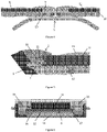
- La
figure 1 représente une vue de face d'une montre-bracelet attachée d'un côté à un bracelet de montre selon la présente invention, - La
figure 2 représente une vue de côté d'une bande flexible amovible, - La
figure 3 représente une vue en perspective partielle de deux brins de bracelet et d'un fermoir dont un capot est ouvert, - La
figure 4 représente une vue de côté partielle en coupe d'un de deux brins de bracelet et d'un fermoir dont les deux capots sont fermés, - La
figure 5 représente une vue en coupe d'une extrémité d'un brin de bracelet connectable à un boitier de montre ; et - La
figure 6 représente une vue en coupe transversale d'un maillon d'un brin de bracelet comportant une bande flexible amovible. - Comme illustré à la
figure 1 , une montre-bracelet comporte un boîtier 3 connecté aux premières extrémités 2 de deux brins 1 d'un bracelet. Chaque brin 1 de bracelet comporte une première extrémité 2 agencée pour être connectée au boîtier 3 de la montre-bracelet, les deux brins 1 étant connectés par leurs secondes extrémités 4 à un fermoir 5. Chaque brin 1 de bracelet comporte en outre une bande flexible amovible 6 qui couvre une partie de la surface externe du brin 1 sur sa longueur. La bande flexible amovible 6 comporte, à la première extrémité 2 du brin, une première projection 7 (voirfigures 2 et5 ) qui vient s'insérer dans une ouverture 8 (figure 5 ) aménagée dans la première extrémité 2 du brin. - Comme illustré à la
figure 5 , la première projection 7 et ladite ouverture 8 du brin 1 comportent des profils complémentaires qui coopèrent pour solidariser de manière amovible la première projection 7 de la bande flexible 6 sur le brin 1. - Comme illustré à la
figure 4 , la seconde extrémité 4 du brin est connectée à un élément d'attache pivoté 9, un capot, du fermoir 5 ayant une position fermée repliée contre le brin et une position ouverte relevée (voirfigure 3 ). La bande flexible amovible 6 comporte, à la seconde extrémité 4 du brin, une seconde projection 10 en forme de pas d'escaliers qui est maintenue en place et cachée par l'élément d'attache pivoté 9 lorsque celui-ci est dans sa position fermée. En effet la face inférieure de l'extrémité de l'élément d'attache pivoté 9 comporte un profil en pas d'escalier complémentaire à celui de la seconde projection 10. De cette manière, lorsque l'élément d'attache pivoté 9 est dans sa position fermée, comme illustré à lafigure 4 , il couvre et bute contre l'extrémité de la projection 10, assurant ainsi un verrouillage efficace de la projection 10. - Comme illustré à la
figure 3 , lorsque le capot 9 est dans sa position ouverte, il libère et donne accès à la seconde projection 10 de la bande flexible 6 pour permettre à l'utilisateur de tirer sur la bande flexible 6 pour désolidariser la première projection 7 (figure 5 ) de la bande flexible du brin. Dans cet exemple, le fermoir 5 est du type fermoir papillon avec boucle invisible. Bien évidemment d'autres types de fermoirs peuvent s'adapter. - Le bracelet illustré notamment aux
figures 1 et 3 comporte une série de maillons articulés 13 disposés de part et d'autre de la bande flexible 6. Les maillons 13 comportent une partie centrale 14 (voirfigure 6 ) et deux supports latéraux 15 (voirfigure 6 ) agencés de part et d'autre de la partie centrale. La bande flexible 6 est configurée pour recouvrir le côté supérieur de la partie centrale des maillons 13 afin que la bande flexible 6 forme une partie supérieure visible du brin 1. - Comme illustré à la
figure 6 , les supports latéraux 15 des maillons comportent des rainures 16 le long du brin agencées pour recevoir les bords latéraux 17 de la bande flexible 6. Dans cet exemple, la couche interne 12 en un matériau glissant tel du caoutchouc ou du plastique s'étend latéralement au-delà de la couche externe 11 par exemple en cuir pour former les bords latéraux 17 de la bande flexible 6 qui sont reçus dans les rainures 16 le long du brin 1. Les deux couches sont solidarisées par exemple par un matériau adhésif adéquate, voire par soudage. - Les deux matériaux de la bande flexible sont utilisés l'un pour l'aspect esthétique et l'autre pour ses qualités de faible coefficient de frottement. Par exemple le plastique ou le caoutchouc sont utilisés pour la couche interne 12 pour abaisser les coefficients de friction de manière à réduire l'énergie nécessaire aux déplacements ainsi qu'à diminuer l'usure lors du contact de la couche interne 12 avec les rainures 16, et pour assurer la solidité de la seconde projection 10.
- Comme illustré à la
figure 2 , la première projection 7 de la bande flexible 6 comporte une cavité 18 peu profonde faisant face vers le haut et dans laquelle vient s'engager une projection 19 (voirfigure 5 ) faisant face vers le bas aménagée dans la première extrémité 2 du brin. La première projection 7 de la bande flexible 6 termine au-delà de ladite cavité 18 peu profonde avec une lèvre 20 qui s'étend légèrement au-dessus de ladite cavité 18 peu profonde. La bande flexible 6 comporte, adjacente à sa première projection 7, une creusure 21 de forme partiellement cylindrique faisant face vers l'extrémité et s'étendant au-dessus et en continuité de ladite cavité 18 peu profonde. - Comme illustré à la
figure 5 , une barrette cylindrique 22 est agencée pour attacher la première extrémité 2 du brin de bracelet à un boîtier de la montre, cette barrette 22 venant s'engager dans l'ouverture à surface partiellement cylindrique formée par la cavité peu profonde et par ladite creusure partiellement cylindrique, pour assurer une solidarisation amovible très sure de la bande flexible. - Comme on voit schématiquement à la
figure 2 , les deux extrémités de la couche externe 11, peuvent être optionnellement pourvues de pièces de renforcement.
Claims (13)
- Brin de bracelet pour une montre-bracelet,le brin (1) de bracelet comportant une première extrémité (2) agencée pour être connectée à un boîtier (3) de la montre, et une seconde extrémité (4) connectée à un fermoir (5),le brin (1) de bracelet comportant en outre une bande flexible amovible (6) qui couvre une partie de la surface externe du brin (1) sur sa longueur,où la bande flexible amovible (6) comporte une première projection (7) et une seconde projection (10),la seconde extrémité (4) du brin étant connectée à un élément d'attache pivoté (9) du fermoir (5) ayant une position fermée repliée contre le brin (1) et une position ouverte relevée,la seconde projection (10) étant maintenue en place et cachée par l'élément d'attache pivoté (9) lorsque celui-ci est dans sa position fermée,caractérisé en ce quela première projection (7) vient s'insérer dans une ouverture (8) aménagée dans la première extrémité (2) du brin, la première projection (7) et ladite ouverture (8) du brin (1) comportant des profils complémentaires qui coopèrent pour solidariser de manière amovible la première projection (7) de la bande flexible (6) sur le brin (1), etlorsque l'élément d'attache pivoté (9) est dans sa position ouverte il libère et donne accès à la seconde projection (10) de la bande flexible (6) pour permettre à l'utilisateur de tirer sur la bande flexible (6) pour désolidariser la première projection (7) de la bande flexible (6) du brin.
- Brin de bracelet selon la revendication 1, où la bande flexible (6) est constituée de deux couches (11, 12) différentes, une couche externe (11) en cuir ou en un matériau ressemblant au cuir, en tissu ou un autre matériau coloré qui est visible de l'extérieur et une couche interne (12) en un matériau glissant.
- Brin de bracelet selon la revendication 1 ou 2, comportant une série de maillons articulés (13) disposés de part et d'autre de la bande flexible (6).
- Brin de bracelet selon la revendication 3, où les maillons (13) comportent une partie centrale (14) et deux supports latéraux (15) agencés de part et d'autre de la partie centrale (14), la bande flexible (6) étant configurée pour recouvrir le côté supérieur de la partie centrale (14) des maillons afin que la bande flexible (6) forme une partie supérieur visible du brin (1).
- Brin de bracelet selon la revendication 4, où les supports latéraux (15) des maillons comportent des rainures (16) le long du brin (1) agencées pour recevoir les bords latéraux (17) de la bande flexible (6).
- Brin de bracelet selon la revendication 5 lorsqu'elle dépend de la revendication 2, où la couche interne (12) en un matériau glissant s'étend latéralement au-delà de la couche externe (11) pour former les bords latéraux (17) de la bande flexible (6) qui sont reçus dans les rainures (16) le long du brin (1).
- Brin de bracelet selon l'une des revendications précédentes, où la première projection (7) de la bande flexible (6) comporte une cavité (18) peu profonde faisant face vers le haut et dans laquelle vient s'engager une projection (19) faisant face vers le bas aménagée dans la première extrémité (2) du brin.
- Brin de bracelet selon la revendication 7, où la première projection (7) de la bande flexible (6) termine au-delà de ladite cavité (18) peu profonde avec une lèvre (20) qui s'étend légèrement au dessus de ladite cavité (18) peu profonde.
- Brin de bracelet selon la revendication 7 ou 8, où la bande flexible (6) comporte, adjacente à sa première projection (7), une creusure (21) de forme partiellement cylindrique faisant face vers l'extrémité et s'étendant au-dessus et en continuité de ladite cavité (18) peu profonde.
- Brin de bracelet selon la revendication 9, comportant une barrette cylindrique (22) agencée pour attacher la première extrémité (2) du brin de bracelet à un boîtier (3) de la montre, cette barrette (22) venant s'engager dans l'ouverture à surface partiellement cylindrique formée par la cavité (18) peu profonde et par ladite creusure (21) partiellement cylindrique.
- Bracelet d'une montre-bracelet, comportant deux brins (1) de bracelet selon l'une des revendications précédentes, chaque brin (1) de bracelet comportant une première extrémité (2) agencée pour être connectée à un boîtier (3) d'un montre-bracelet, les deux brins (1) étant connectés par leurs secondes extrémités (4) à un fermoir (5).
- Bracelet selon la revendication 11, où le fermoir (5) est du type comportant des bras articulés déployables comportant, à chaque brin (1) de bracelet, un élément d'attache pivoté (9).
- Montre-bracelet comportant un bracelet selon la revendication 11 ou 12 et un boîtier (3) connecté aux premières extrémités (2) de deux brins (1) du bracelet.
Applications Claiming Priority (2)
| Application Number | Priority Date | Filing Date | Title |
|---|---|---|---|
| CH00473/18A CH714888A1 (fr) | 2018-04-13 | 2018-04-13 | Brin de bracelet pour montre-bracelet. |
| PCT/IB2019/051000 WO2019197911A1 (fr) | 2018-04-13 | 2019-02-07 | Brin de bracelet pour montre-bracelet |
Publications (2)
| Publication Number | Publication Date |
|---|---|
| EP3773054A1 EP3773054A1 (fr) | 2021-02-17 |
| EP3773054B1 true EP3773054B1 (fr) | 2022-06-22 |
Family
ID=65724486
Family Applications (1)
| Application Number | Title | Priority Date | Filing Date |
|---|---|---|---|
| EP19710145.4A Active EP3773054B1 (fr) | 2018-04-13 | 2019-02-07 | Brin de bracelet pour montre-bracelet |
Country Status (3)
| Country | Link |
|---|---|
| EP (1) | EP3773054B1 (fr) |
| CH (1) | CH714888A1 (fr) |
| WO (1) | WO2019197911A1 (fr) |
Family Cites Families (10)
| Publication number | Priority date | Publication date | Assignee | Title |
|---|---|---|---|---|
| CH325212A (fr) * | 1955-10-08 | 1957-10-31 | Humbert & Cie S A | Bracelet |
| DE2905164C2 (de) * | 1979-02-10 | 1981-04-30 | Trend-Team AG, Ennetbürgen | Uhrarmband |
| DE8805454U1 (de) * | 1988-04-25 | 1988-06-23 | Gerhard D. Wempe KG, 2000 Hamburg | Armband, insbesondere Uhrenarmband |
| IT227994Y1 (it) | 1992-02-28 | 1998-02-05 | Morellato Spa | Struttura di cinturino |
| JPH0984608A (ja) * | 1995-09-20 | 1997-03-31 | Casio Comput Co Ltd | バンド |
| US6195977B1 (en) * | 1997-04-25 | 2001-03-06 | Malboussin Horlogers | Watchband with articulate links |
| DE69800365T2 (de) * | 1998-07-03 | 2001-05-17 | Protaurec S.A.R.L., Les Genevez | Mehrgliedriges Armband mit einer biegsamen Fassung und Verfahren zur dessen Herstellung |
| WO2000030434A1 (fr) | 1998-11-19 | 2000-06-02 | Noguero Elena M | Collier decoratif et procede de modification de l'aspect d'un collier |
| CH704963B1 (fr) * | 2011-05-16 | 2015-08-14 | Buccellati Watches Sa | Bracelet pour une pièce d'horlogerie. |
| GB2509512A (en) * | 2013-01-04 | 2014-07-09 | John Finlan | Flexible strap |
-
2018
- 2018-04-13 CH CH00473/18A patent/CH714888A1/fr not_active Application Discontinuation
-
2019
- 2019-02-07 WO PCT/IB2019/051000 patent/WO2019197911A1/fr not_active Ceased
- 2019-02-07 EP EP19710145.4A patent/EP3773054B1/fr active Active
Also Published As
| Publication number | Publication date |
|---|---|
| CH714888A1 (fr) | 2019-10-15 |
| WO2019197911A1 (fr) | 2019-10-17 |
| EP3773054A1 (fr) | 2021-02-17 |
Similar Documents
| Publication | Publication Date | Title |
|---|---|---|
| FR2735955A1 (fr) | Fermoir de cordon | |
| CH704810B1 (fr) | Brin de bracelet flexible. | |
| FR2809598A1 (fr) | Fermeture a glissiere a accouplement avec dispositif d'accrochage | |
| WO2018158508A1 (fr) | Élément décoratif portatif comportant une garniture plaquée sous une structure rigide ajourée | |
| FR2546729A1 (fr) | Fermoir amovible | |
| FR2565079A1 (fr) | Boucle liberable, en particulier pour sacs, sacoches et autres | |
| FR2694872A1 (fr) | Barrette à cheveux. | |
| EP3773054B1 (fr) | Brin de bracelet pour montre-bracelet | |
| EP0126382A1 (fr) | Fermoir extensible pour bracelet flexible, notamment pour bracelet-montre | |
| FR2504997A1 (fr) | Mousqueton en plastique pour fermeture de ceintures et analogues | |
| EP1338214B1 (fr) | Fermeture a laniere pour montre, bijou, sac ou analogue | |
| FR2472356A1 (fr) | Bande d'accrochage pour fermeture a glissiere | |
| CH669316A5 (en) | Articulated watch bracelet made of plastics material - has links with central row of elements joined to outer rows by studs engaging in holes | |
| EP0336848B1 (fr) | Dispositif de marquage à poser sur l'oreille d'un animal | |
| WO2018011774A1 (fr) | Dispositif de fermeture | |
| EP0608580A1 (fr) | Boucle de fermeture | |
| EP1192872B1 (fr) | Fermoir pour assembler deux brins souples utilisable, notamment, pour un bracelet de montre | |
| EP0208345B1 (fr) | Fermoir pour bracelet métallique | |
| CH710931B1 (fr) | Dispositif comportant une sangle et un module à fonction électronique intégré dans un fermoir. | |
| EP1799061B1 (fr) | Article de bijouterie comprenant un systeme de liaison articule entre deux elements | |
| FR2679111A1 (fr) | Bijou polyvalent formant attache pour foulard, echarpe et similaire. | |
| FR2472357A1 (fr) | Laniere de montre-bracelet a extremite de fixation reglable | |
| FR2629693A1 (fr) | Fermoir pour bracelet, ceinture ou autre objet du meme type | |
| BE1001389A7 (fr) | Cravate prenouee reglable. | |
| EP4670561A1 (fr) | Boucle de ceinture, notamment de maroquinerie, et ceinture, notamment de maroquinerie, comportant une telle boucle |
Legal Events
| Date | Code | Title | Description |
|---|---|---|---|
| STAA | Information on the status of an ep patent application or granted ep patent |
Free format text: STATUS: UNKNOWN |
|
| STAA | Information on the status of an ep patent application or granted ep patent |
Free format text: STATUS: THE INTERNATIONAL PUBLICATION HAS BEEN MADE |
|
| PUAI | Public reference made under article 153(3) epc to a published international application that has entered the european phase |
Free format text: ORIGINAL CODE: 0009012 |
|
| STAA | Information on the status of an ep patent application or granted ep patent |
Free format text: STATUS: REQUEST FOR EXAMINATION WAS MADE |
|
| 17P | Request for examination filed |
Effective date: 20201103 |
|
| AK | Designated contracting states |
Kind code of ref document: A1 Designated state(s): AL AT BE BG CH CY CZ DE DK EE ES FI FR GB GR HR HU IE IS IT LI LT LU LV MC MK MT NL NO PL PT RO RS SE SI SK SM TR |
|
| AX | Request for extension of the european patent |
Extension state: BA ME |
|
| DAV | Request for validation of the european patent (deleted) | ||
| DAX | Request for extension of the european patent (deleted) | ||
| GRAP | Despatch of communication of intention to grant a patent |
Free format text: ORIGINAL CODE: EPIDOSNIGR1 |
|
| STAA | Information on the status of an ep patent application or granted ep patent |
Free format text: STATUS: GRANT OF PATENT IS INTENDED |
|
| INTG | Intention to grant announced |
Effective date: 20220107 |
|
| GRAS | Grant fee paid |
Free format text: ORIGINAL CODE: EPIDOSNIGR3 |
|
| GRAA | (expected) grant |
Free format text: ORIGINAL CODE: 0009210 |
|
| STAA | Information on the status of an ep patent application or granted ep patent |
Free format text: STATUS: THE PATENT HAS BEEN GRANTED |
|
| AK | Designated contracting states |
Kind code of ref document: B1 Designated state(s): AL AT BE BG CH CY CZ DE DK EE ES FI FR GB GR HR HU IE IS IT LI LT LU LV MC MK MT NL NO PL PT RO RS SE SI SK SM TR |
|
| REG | Reference to a national code |
Ref country code: GB Ref legal event code: FG4D Free format text: NOT ENGLISH |
|
| REG | Reference to a national code |
Ref country code: CH Ref legal event code: EP |
|
| REG | Reference to a national code |
Ref country code: DE Ref legal event code: R096 Ref document number: 602019016152 Country of ref document: DE |
|
| REG | Reference to a national code |
Ref country code: AT Ref legal event code: REF Ref document number: 1499217 Country of ref document: AT Kind code of ref document: T Effective date: 20220715 |
|
| REG | Reference to a national code |
Ref country code: IE Ref legal event code: FG4D Free format text: LANGUAGE OF EP DOCUMENT: FRENCH |
|
| REG | Reference to a national code |
Ref country code: LT Ref legal event code: MG9D |
|
| REG | Reference to a national code |
Ref country code: NL Ref legal event code: MP Effective date: 20220622 |
|
| PG25 | Lapsed in a contracting state [announced via postgrant information from national office to epo] |
Ref country code: SE Free format text: LAPSE BECAUSE OF FAILURE TO SUBMIT A TRANSLATION OF THE DESCRIPTION OR TO PAY THE FEE WITHIN THE PRESCRIBED TIME-LIMIT Effective date: 20220622 Ref country code: NO Free format text: LAPSE BECAUSE OF FAILURE TO SUBMIT A TRANSLATION OF THE DESCRIPTION OR TO PAY THE FEE WITHIN THE PRESCRIBED TIME-LIMIT Effective date: 20220922 Ref country code: LT Free format text: LAPSE BECAUSE OF FAILURE TO SUBMIT A TRANSLATION OF THE DESCRIPTION OR TO PAY THE FEE WITHIN THE PRESCRIBED TIME-LIMIT Effective date: 20220622 Ref country code: HR Free format text: LAPSE BECAUSE OF FAILURE TO SUBMIT A TRANSLATION OF THE DESCRIPTION OR TO PAY THE FEE WITHIN THE PRESCRIBED TIME-LIMIT Effective date: 20220622 Ref country code: GR Free format text: LAPSE BECAUSE OF FAILURE TO SUBMIT A TRANSLATION OF THE DESCRIPTION OR TO PAY THE FEE WITHIN THE PRESCRIBED TIME-LIMIT Effective date: 20220923 Ref country code: FI Free format text: LAPSE BECAUSE OF FAILURE TO SUBMIT A TRANSLATION OF THE DESCRIPTION OR TO PAY THE FEE WITHIN THE PRESCRIBED TIME-LIMIT Effective date: 20220622 Ref country code: BG Free format text: LAPSE BECAUSE OF FAILURE TO SUBMIT A TRANSLATION OF THE DESCRIPTION OR TO PAY THE FEE WITHIN THE PRESCRIBED TIME-LIMIT Effective date: 20220922 |
|
| REG | Reference to a national code |
Ref country code: AT Ref legal event code: MK05 Ref document number: 1499217 Country of ref document: AT Kind code of ref document: T Effective date: 20220622 |
|
| PG25 | Lapsed in a contracting state [announced via postgrant information from national office to epo] |
Ref country code: RS Free format text: LAPSE BECAUSE OF FAILURE TO SUBMIT A TRANSLATION OF THE DESCRIPTION OR TO PAY THE FEE WITHIN THE PRESCRIBED TIME-LIMIT Effective date: 20220622 Ref country code: LV Free format text: LAPSE BECAUSE OF FAILURE TO SUBMIT A TRANSLATION OF THE DESCRIPTION OR TO PAY THE FEE WITHIN THE PRESCRIBED TIME-LIMIT Effective date: 20220622 |
|
| PG25 | Lapsed in a contracting state [announced via postgrant information from national office to epo] |
Ref country code: NL Free format text: LAPSE BECAUSE OF FAILURE TO SUBMIT A TRANSLATION OF THE DESCRIPTION OR TO PAY THE FEE WITHIN THE PRESCRIBED TIME-LIMIT Effective date: 20220622 |
|
| PG25 | Lapsed in a contracting state [announced via postgrant information from national office to epo] |
Ref country code: SM Free format text: LAPSE BECAUSE OF FAILURE TO SUBMIT A TRANSLATION OF THE DESCRIPTION OR TO PAY THE FEE WITHIN THE PRESCRIBED TIME-LIMIT Effective date: 20220622 Ref country code: SK Free format text: LAPSE BECAUSE OF FAILURE TO SUBMIT A TRANSLATION OF THE DESCRIPTION OR TO PAY THE FEE WITHIN THE PRESCRIBED TIME-LIMIT Effective date: 20220622 Ref country code: RO Free format text: LAPSE BECAUSE OF FAILURE TO SUBMIT A TRANSLATION OF THE DESCRIPTION OR TO PAY THE FEE WITHIN THE PRESCRIBED TIME-LIMIT Effective date: 20220622 Ref country code: PT Free format text: LAPSE BECAUSE OF FAILURE TO SUBMIT A TRANSLATION OF THE DESCRIPTION OR TO PAY THE FEE WITHIN THE PRESCRIBED TIME-LIMIT Effective date: 20221024 Ref country code: ES Free format text: LAPSE BECAUSE OF FAILURE TO SUBMIT A TRANSLATION OF THE DESCRIPTION OR TO PAY THE FEE WITHIN THE PRESCRIBED TIME-LIMIT Effective date: 20220622 Ref country code: EE Free format text: LAPSE BECAUSE OF FAILURE TO SUBMIT A TRANSLATION OF THE DESCRIPTION OR TO PAY THE FEE WITHIN THE PRESCRIBED TIME-LIMIT Effective date: 20220622 Ref country code: CZ Free format text: LAPSE BECAUSE OF FAILURE TO SUBMIT A TRANSLATION OF THE DESCRIPTION OR TO PAY THE FEE WITHIN THE PRESCRIBED TIME-LIMIT Effective date: 20220622 Ref country code: AT Free format text: LAPSE BECAUSE OF FAILURE TO SUBMIT A TRANSLATION OF THE DESCRIPTION OR TO PAY THE FEE WITHIN THE PRESCRIBED TIME-LIMIT Effective date: 20220622 |
|
| PG25 | Lapsed in a contracting state [announced via postgrant information from national office to epo] |
Ref country code: PL Free format text: LAPSE BECAUSE OF FAILURE TO SUBMIT A TRANSLATION OF THE DESCRIPTION OR TO PAY THE FEE WITHIN THE PRESCRIBED TIME-LIMIT Effective date: 20220622 Ref country code: IS Free format text: LAPSE BECAUSE OF FAILURE TO SUBMIT A TRANSLATION OF THE DESCRIPTION OR TO PAY THE FEE WITHIN THE PRESCRIBED TIME-LIMIT Effective date: 20221022 |
|
| REG | Reference to a national code |
Ref country code: DE Ref legal event code: R097 Ref document number: 602019016152 Country of ref document: DE |
|
| PG25 | Lapsed in a contracting state [announced via postgrant information from national office to epo] |
Ref country code: AL Free format text: LAPSE BECAUSE OF FAILURE TO SUBMIT A TRANSLATION OF THE DESCRIPTION OR TO PAY THE FEE WITHIN THE PRESCRIBED TIME-LIMIT Effective date: 20220622 |
|
| PG25 | Lapsed in a contracting state [announced via postgrant information from national office to epo] |
Ref country code: DK Free format text: LAPSE BECAUSE OF FAILURE TO SUBMIT A TRANSLATION OF THE DESCRIPTION OR TO PAY THE FEE WITHIN THE PRESCRIBED TIME-LIMIT Effective date: 20220622 |
|
| PLBE | No opposition filed within time limit |
Free format text: ORIGINAL CODE: 0009261 |
|
| STAA | Information on the status of an ep patent application or granted ep patent |
Free format text: STATUS: NO OPPOSITION FILED WITHIN TIME LIMIT |
|
| 26N | No opposition filed |
Effective date: 20230323 |
|
| P01 | Opt-out of the competence of the unified patent court (upc) registered |
Effective date: 20230605 |
|
| PG25 | Lapsed in a contracting state [announced via postgrant information from national office to epo] |
Ref country code: SI Free format text: LAPSE BECAUSE OF FAILURE TO SUBMIT A TRANSLATION OF THE DESCRIPTION OR TO PAY THE FEE WITHIN THE PRESCRIBED TIME-LIMIT Effective date: 20220622 |
|
| REG | Reference to a national code |
Ref country code: DE Ref legal event code: R119 Ref document number: 602019016152 Country of ref document: DE |
|
| PG25 | Lapsed in a contracting state [announced via postgrant information from national office to epo] |
Ref country code: MC Free format text: LAPSE BECAUSE OF FAILURE TO SUBMIT A TRANSLATION OF THE DESCRIPTION OR TO PAY THE FEE WITHIN THE PRESCRIBED TIME-LIMIT Effective date: 20220622 |
|
| REG | Reference to a national code |
Ref country code: BE Ref legal event code: MM Effective date: 20230228 |
|
| GBPC | Gb: european patent ceased through non-payment of renewal fee |
Effective date: 20230207 |
|
| PG25 | Lapsed in a contracting state [announced via postgrant information from national office to epo] |
Ref country code: LU Free format text: LAPSE BECAUSE OF NON-PAYMENT OF DUE FEES Effective date: 20230207 |
|
| REG | Reference to a national code |
Ref country code: IE Ref legal event code: MM4A |
|
| PG25 | Lapsed in a contracting state [announced via postgrant information from national office to epo] |
Ref country code: GB Free format text: LAPSE BECAUSE OF NON-PAYMENT OF DUE FEES Effective date: 20230207 |
|
| PG25 | Lapsed in a contracting state [announced via postgrant information from national office to epo] |
Ref country code: IT Free format text: LAPSE BECAUSE OF FAILURE TO SUBMIT A TRANSLATION OF THE DESCRIPTION OR TO PAY THE FEE WITHIN THE PRESCRIBED TIME-LIMIT Effective date: 20220622 Ref country code: IE Free format text: LAPSE BECAUSE OF NON-PAYMENT OF DUE FEES Effective date: 20230207 Ref country code: GB Free format text: LAPSE BECAUSE OF NON-PAYMENT OF DUE FEES Effective date: 20230207 Ref country code: FR Free format text: LAPSE BECAUSE OF NON-PAYMENT OF DUE FEES Effective date: 20230228 Ref country code: DE Free format text: LAPSE BECAUSE OF NON-PAYMENT OF DUE FEES Effective date: 20230901 |
|
| PG25 | Lapsed in a contracting state [announced via postgrant information from national office to epo] |
Ref country code: BE Free format text: LAPSE BECAUSE OF NON-PAYMENT OF DUE FEES Effective date: 20230228 |
|
| PG25 | Lapsed in a contracting state [announced via postgrant information from national office to epo] |
Ref country code: BG Free format text: LAPSE BECAUSE OF FAILURE TO SUBMIT A TRANSLATION OF THE DESCRIPTION OR TO PAY THE FEE WITHIN THE PRESCRIBED TIME-LIMIT Effective date: 20220622 |
|
| PG25 | Lapsed in a contracting state [announced via postgrant information from national office to epo] |
Ref country code: BG Free format text: LAPSE BECAUSE OF FAILURE TO SUBMIT A TRANSLATION OF THE DESCRIPTION OR TO PAY THE FEE WITHIN THE PRESCRIBED TIME-LIMIT Effective date: 20220622 |
|
| PG25 | Lapsed in a contracting state [announced via postgrant information from national office to epo] |
Ref country code: CY Free format text: LAPSE BECAUSE OF FAILURE TO SUBMIT A TRANSLATION OF THE DESCRIPTION OR TO PAY THE FEE WITHIN THE PRESCRIBED TIME-LIMIT; INVALID AB INITIO Effective date: 20190207 |
|
| PG25 | Lapsed in a contracting state [announced via postgrant information from national office to epo] |
Ref country code: HU Free format text: LAPSE BECAUSE OF FAILURE TO SUBMIT A TRANSLATION OF THE DESCRIPTION OR TO PAY THE FEE WITHIN THE PRESCRIBED TIME-LIMIT; INVALID AB INITIO Effective date: 20190207 |
|
| PG25 | Lapsed in a contracting state [announced via postgrant information from national office to epo] |
Ref country code: TR Free format text: LAPSE BECAUSE OF FAILURE TO SUBMIT A TRANSLATION OF THE DESCRIPTION OR TO PAY THE FEE WITHIN THE PRESCRIBED TIME-LIMIT Effective date: 20220622 |
|
| REG | Reference to a national code |
Ref country code: CH Ref legal event code: R18 Free format text: ST27 STATUS EVENT CODE: U-0-0-R10-R18 (AS PROVIDED BY THE NATIONAL OFFICE) Effective date: 20260109 |
|
| REG | Reference to a national code |
Ref country code: CH Ref legal event code: U11 Free format text: ST27 STATUS EVENT CODE: U-0-0-U10-U11 (AS PROVIDED BY THE NATIONAL OFFICE) Effective date: 20260301 |
|
| PGFP | Annual fee paid to national office [announced via postgrant information from national office to epo] |
Ref country code: CH Payment date: 20260301 Year of fee payment: 8 |